

NavyShooter
-
Posts
438 -
Joined
-
Last visited
Content Type
Profiles
Forums
Gallery
Events
Posts posted by NavyShooter
-
-
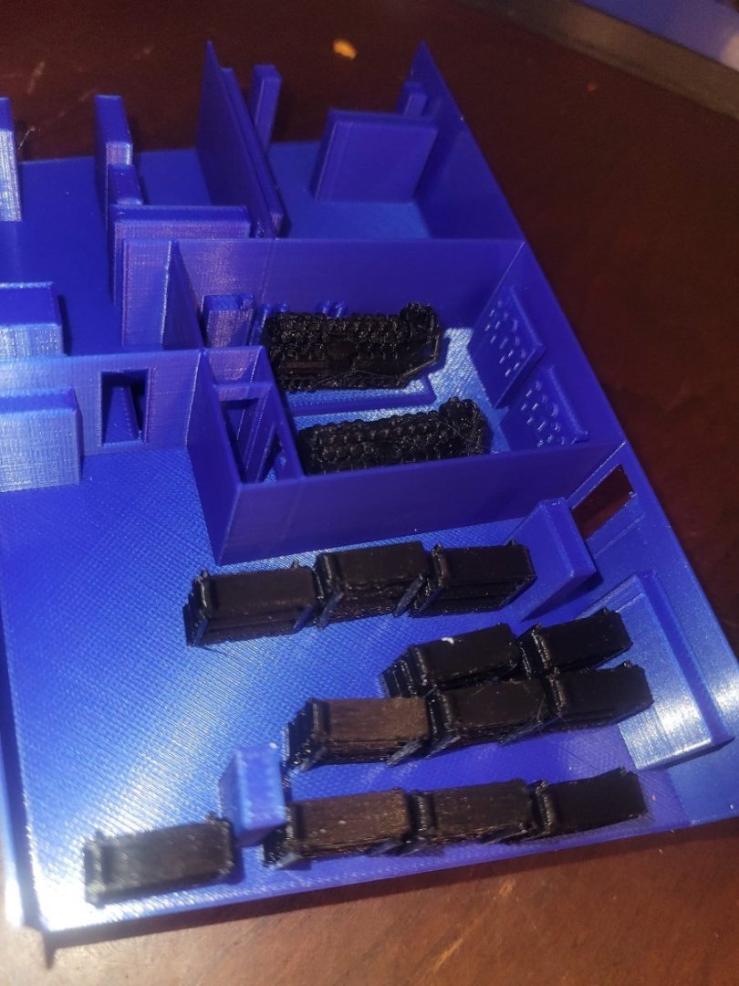
OK, here's the draft version of 4 and 5 decks, with some bunks and the diesels in place.
Lots of printing left to do, and I've still got to test fit the 4 deck module in place to see how it fits in the hull. It will get re-printed after the test.
- GrandpaPhil, yvesvidal, AON and 3 others
-
 6
6
-
-
I'm working on a Titanic model as well (other thread below) but mine is no-where near this level of precision or detail. I'm literally building a pond-float display model that'll be seen from 50+ feet away.
Your model will stand up to 50mm away inspection.
Impressive work, and well done on the hawse-pipe!
NS
-
-
Rabbit holes are fun...here's where I'm at now...I have to print the bunks as separate items that I'll end up gluing into place, but I can do the lockers in situ.
Here you have 4 deck on the left, and 5 deck on the right.

- mtaylor, Keith Black, yvesvidal and 3 others
-
6
-
After a hiatus, the Bonnie came down off the wall today for a little visit. A friend of my wife had her dad along for a visit today, and he sailed on the Bonnie, he was an Electrician's Mate and had some great stories to tell. He really enjoyed going through the ship with me.
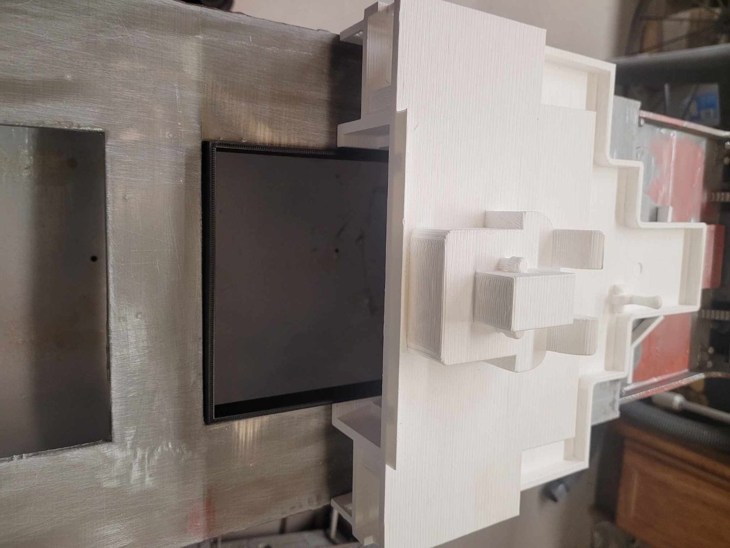
Turns out he slept in 5D2 Mess....so...I spent a bit of time looking at the plans, then dug into DSM and did some 3D design work.
I'm going to try out 'organic' supports as I 3D print his former mess deck.
Here's what the model looks like:


- Keith Black, mtaylor, Canute and 2 others
-
5
-
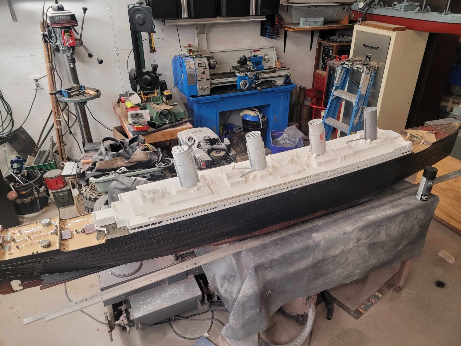
I picked up some tan (sand) paint to use for the decks. We'll see how that works. I laid on the superstructure and the funnels...just to see how things look.
She's massive!

- GrandpaPhil, mtaylor, Mirabell61 and 2 others
-
5
-
Thanks gents. Dad had a brain bleed last year which he recovered from - I looked at every day we had him since that time as a bonus. We got an extra year with him, and he ended up recovering almost 90% from the brain bleed (Subdural hematoma...he got it when he fell off his bicycle during a 10km ride he did one day.)
In terms of additional progress on the Titanic...she's now got 3 layers of resin on the coamings sealing them up, which looks pretty good. I decided to put on a shot coat of black on the hull to see how she looks.
I LIKE IT.

- mtaylor, Canute, GrandpaPhil and 2 others
-
5
-
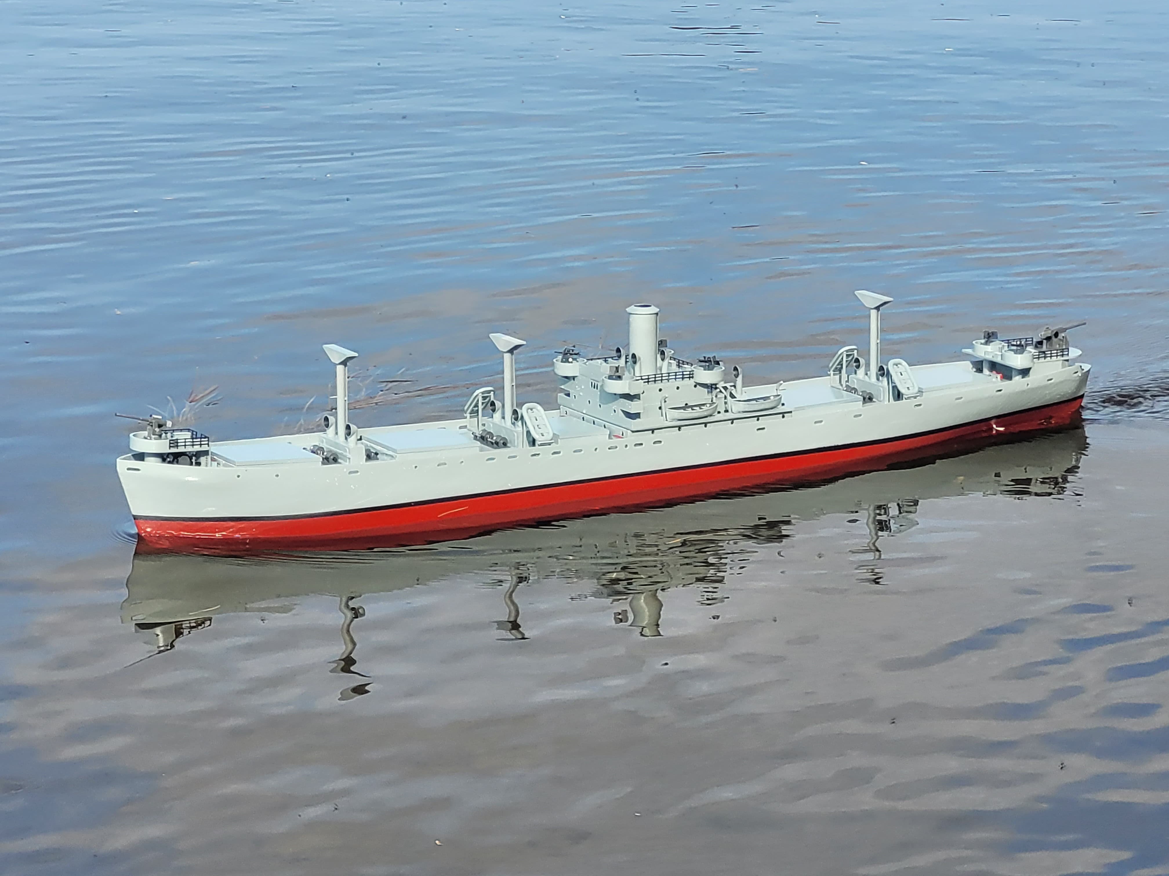
With the planned launch into the park being several months away, the thought occurred to me that the model should be on display somewhere other than in my garage sitting on a table-saw.
My son went to a presentation at a local veteran's organization, and while they had some 'army' stuff around, for this being a Navy town, they had very little in terms of Naval hardware on display...so...they now have a model ship on temporary loan that, if I might say, looks quite good on a live edge table display.
Also, before I headed over, I added a few pieces of line to act as a basic form of rigging for the model. Now I'll call it done.
- yvesvidal, mtaylor, chris watton and 1 other
-
4
-
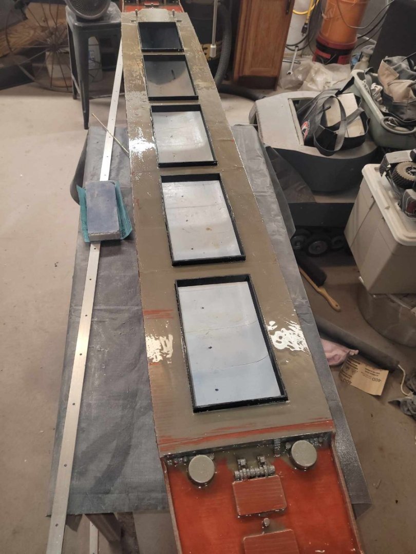
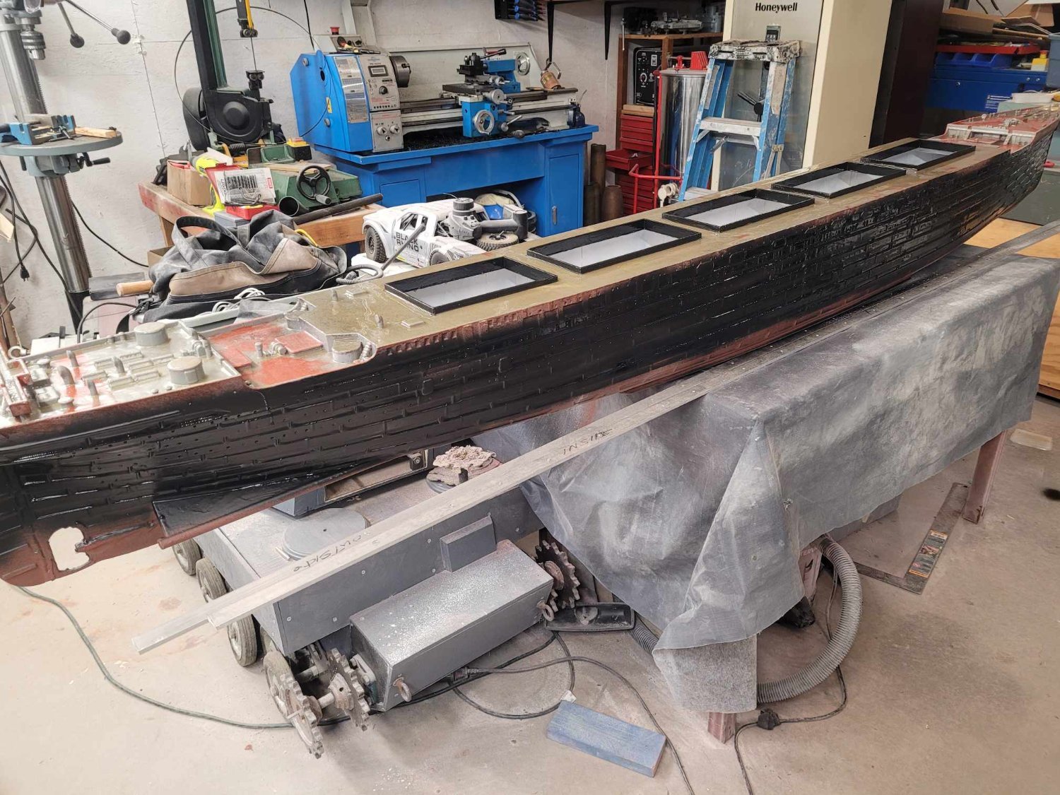
Here are the final versions. I had to reprint the test one at 20mm height, and the other 4 were split into halves which I had to glue together before I glued them in from below.
Once they were glued in place, I put a layer of fiberglass resin overtop to seal them, and fill the holes/gaps.
I'm generally pleased. Needs one more layer I think then it'll be good to go.
-
Well, life is...life. 5 days after my last post, I had to head up to see Dad as he was admitted and intubated at the hospital. He passed on the 29th. I got to see him, he recognized me, and family, and he passed surrounded by those he loved. So. Suffice to say there's been a pause in the build whilst dealing with the immediacy of that.
For those of us who are over a certain age, I will strongly suggest that you make sure your plans are in order. You never know when things will go wrong, and it's extremely unlikely that you'll have a family that actually gets along enough not to fight over the inheritance.
That said, I got home and have been getting caught up on things here, and finally have had time now to head out to the garage to get things going again on this project.
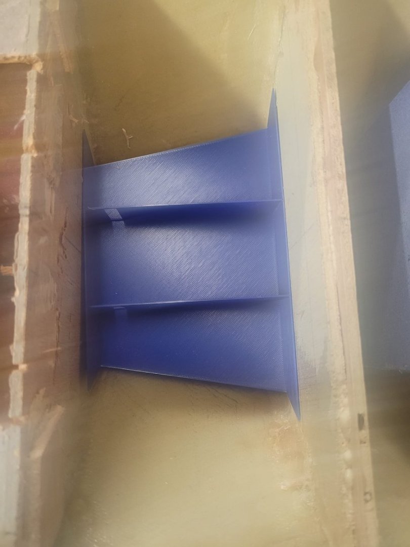
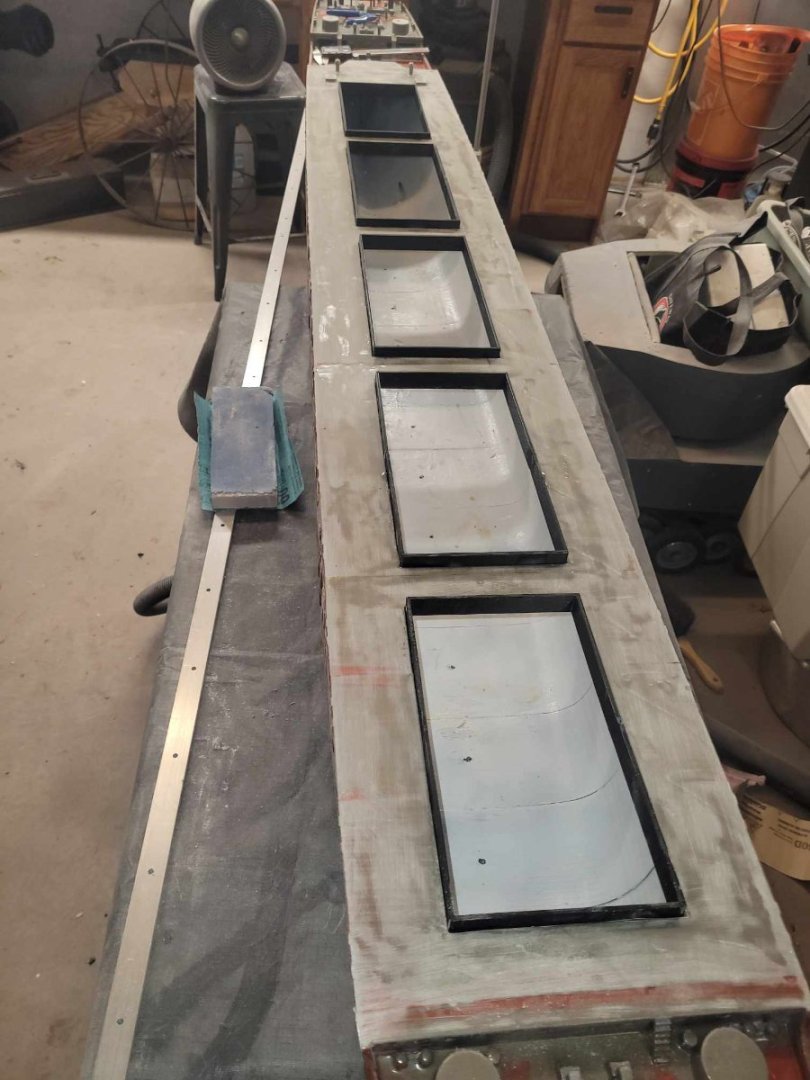
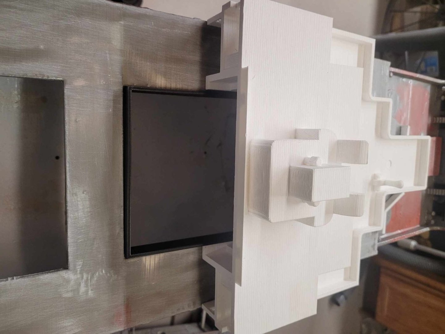
Over the past few days, I realized that I needed to have a raised coaming around each of the 5 holes on the upper hull. Having the superstructure sit down on them for alignment is good...but having a coaming to route water away is more important. So.
I took some measurements, and made a 'draft' copy. It was 14mm high, and that wasn't enough...but it gave me a good idea of what right should look like, so here's the draft.
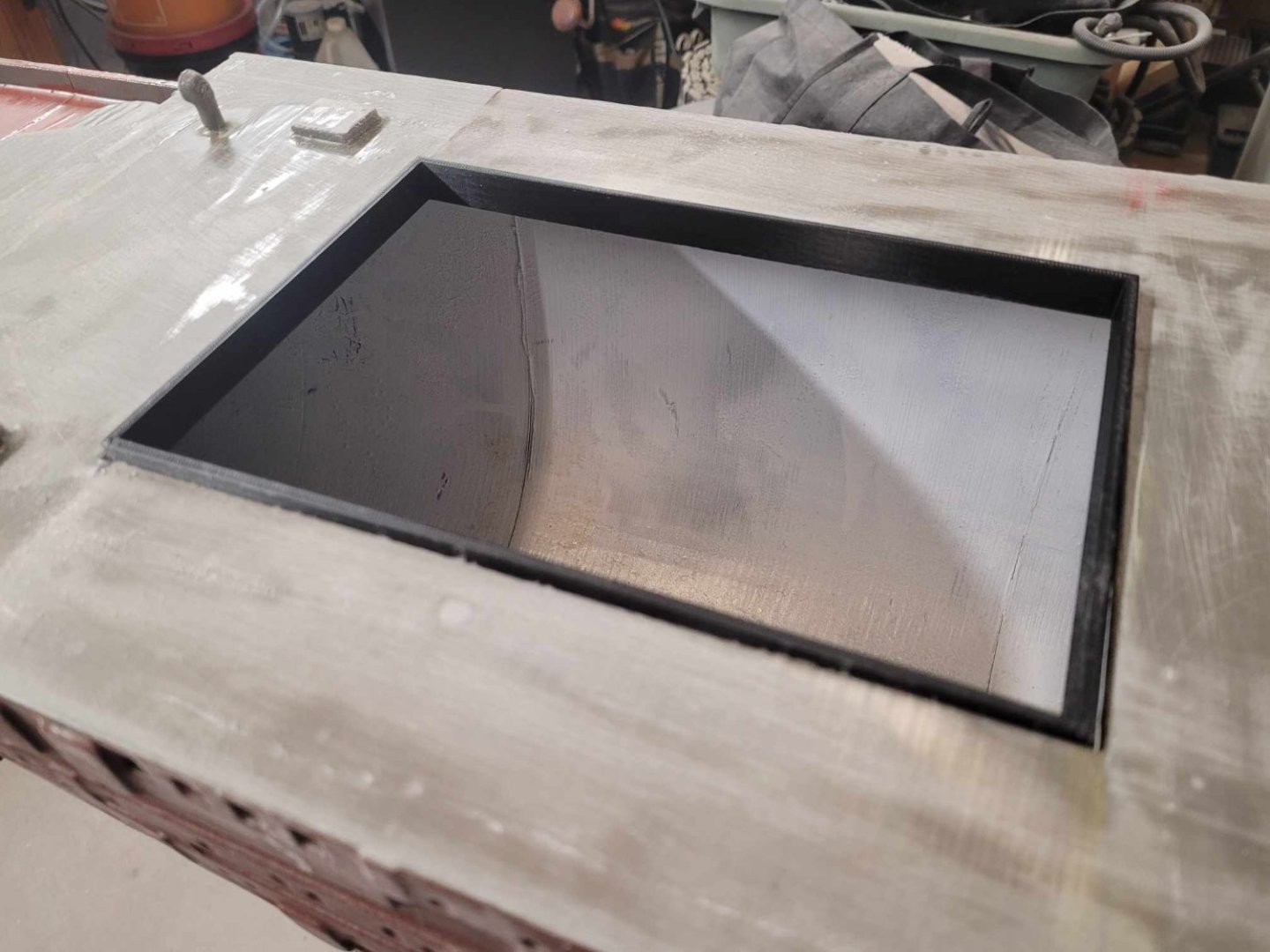
This one is in the rear-most hole, and it's small enough to print in a single piece on my printer, so I did that. It's got a lip that locks up underneath, and basically is a press-fit in from below.

-
I had the 1/35 motorized Jagdtiger many moons ago. Built that up as a kid and loved it.
I also found the 1/35 RC Flakpanzer Gepard - I sold it a few years ago - new in the box. Box was open, but never assembled. All the sprues were still sealed in plastic bags.
I've built the 1/25 Panther that Tamiya made in full RC along with the 1/35 Tiger. That was back in about 2001 or so. Kept me busy while at sea in the Persian Gulf for 6 months.
- mtaylor, Canute, Old Collingwood and 1 other
-
4
-
Welcome aboard!
What part of our nation do you hang your hat in? I'm on the east coast in Halifax area.
NS
- Keith Black, JeffT and mtaylor
-
3
-
-
-
-
-
-
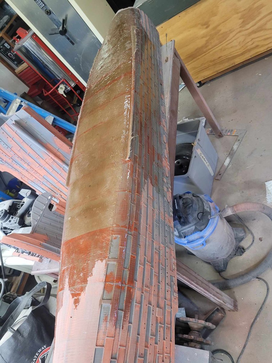
Second Layer applied to the port side.
It's drying now, and I think I'm going to head out to the garage again after my coffee and see if I can get a layer on the Stbd Side too.

- Canute, mtaylor, GrandpaPhil and 1 other
-
4
-
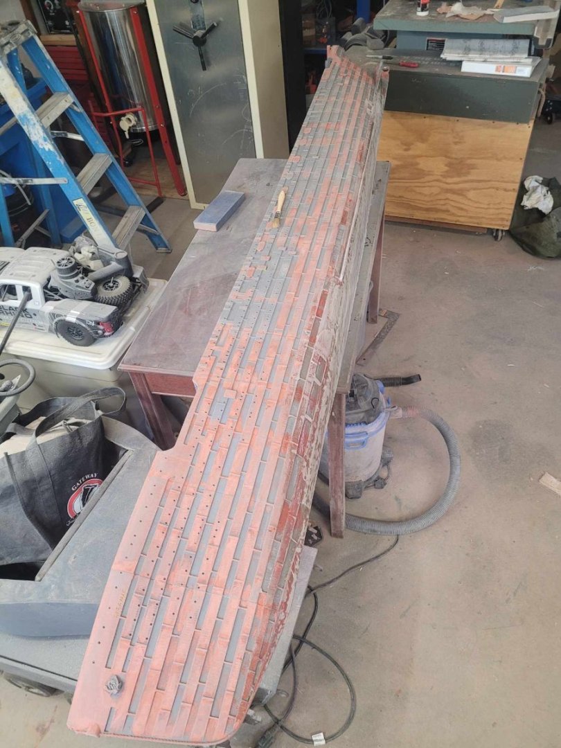
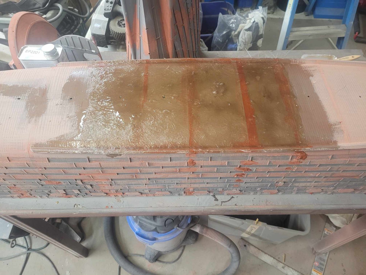
Here's how she looks this afternoon. My hope is to get another layer on this side today, and maybe a couple of layers on the other side as well. She won't be water-tight (shaft line holes to fill first) but damn near.
- GrandpaPhil, scrubbyj427, mtaylor and 3 others
-
6
-
-
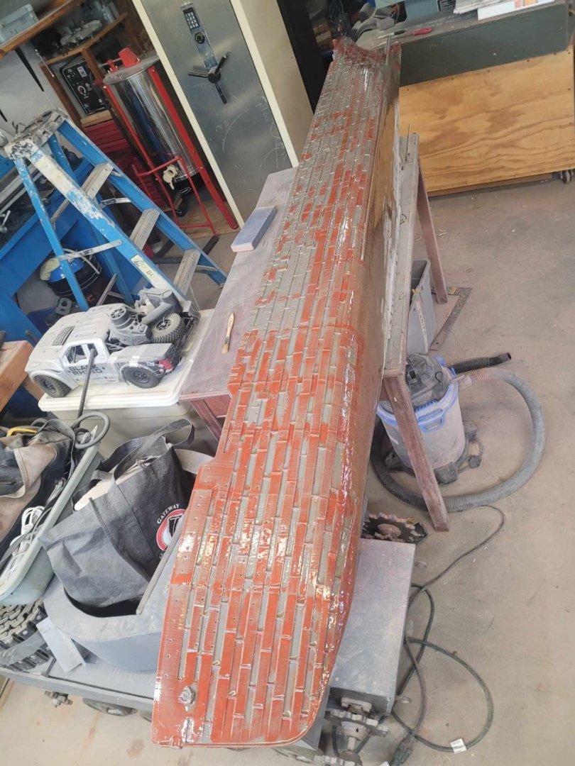
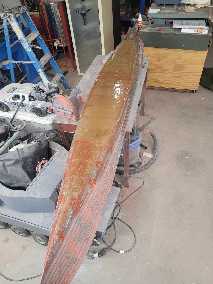
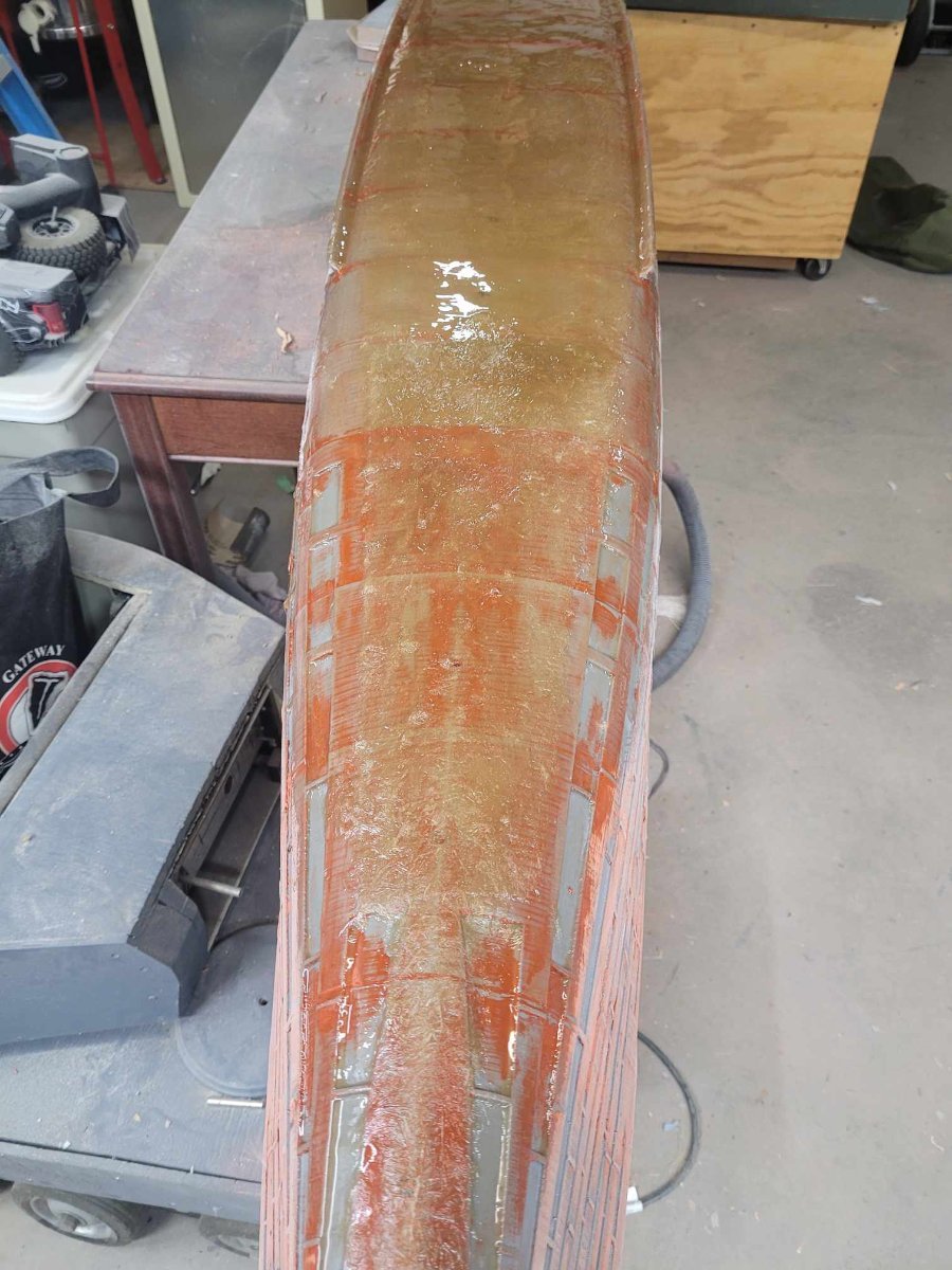
A few more minutes out in the garage, and the full hull is now glued together, a quick sanding was done over the last layer of resin, and a full layer of resin was applied over the sanded section - the rough parts over the mat is now looking pretty smooth.
Goal for tomorrow (I'm off work) is to get both sides of the hull coated with at least 2 layers of resin to seal them in.
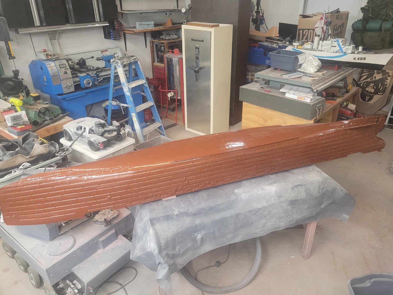
Then, maybe Wednesday evening, I'll have time to shoot a layer of red paint over the hull to see how it looks.
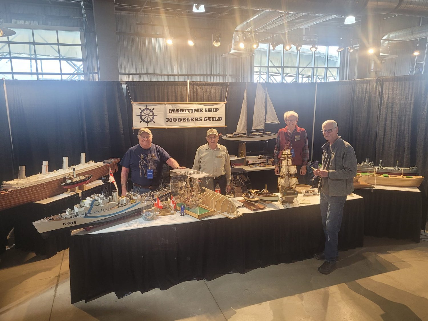
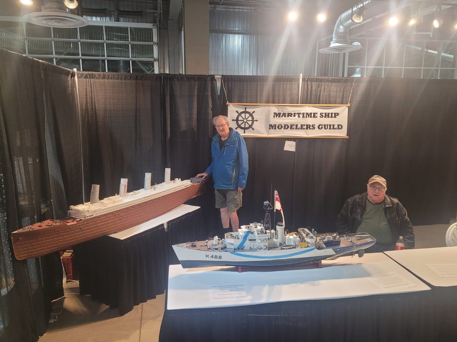
Goal is to have *something* worthy of showing at the craft/hobby show this weekend. The Guild will be represented at a table or two, and I've promised some...stuff...
-
The plan for this one involves having a solar powered bilge pump installed as a 'just in case', and once the ballast is in and sorted out, the intent is to have the rest of the volume of the hull filled with Styrofoam to prevent the ship from 'going down' even if the worst case happened and she did spring a leak.
This is, as I think I explained, version 3 that our Guild is providing to the Public Gardens. Version 1 lasted about 15 years, and was retired to a Guild member's backyard. Version 2 lasted about 4.5 years, having sank last fall, and spending the winter on the bottom of the pond. Version 2 is the one you see in the first post with the plumbing pipe at the bow.
My hope is that this one stays afloat for a few more years once I get her finished!
- KeithAug, GrandpaPhil, mtaylor and 2 others
-
5
-
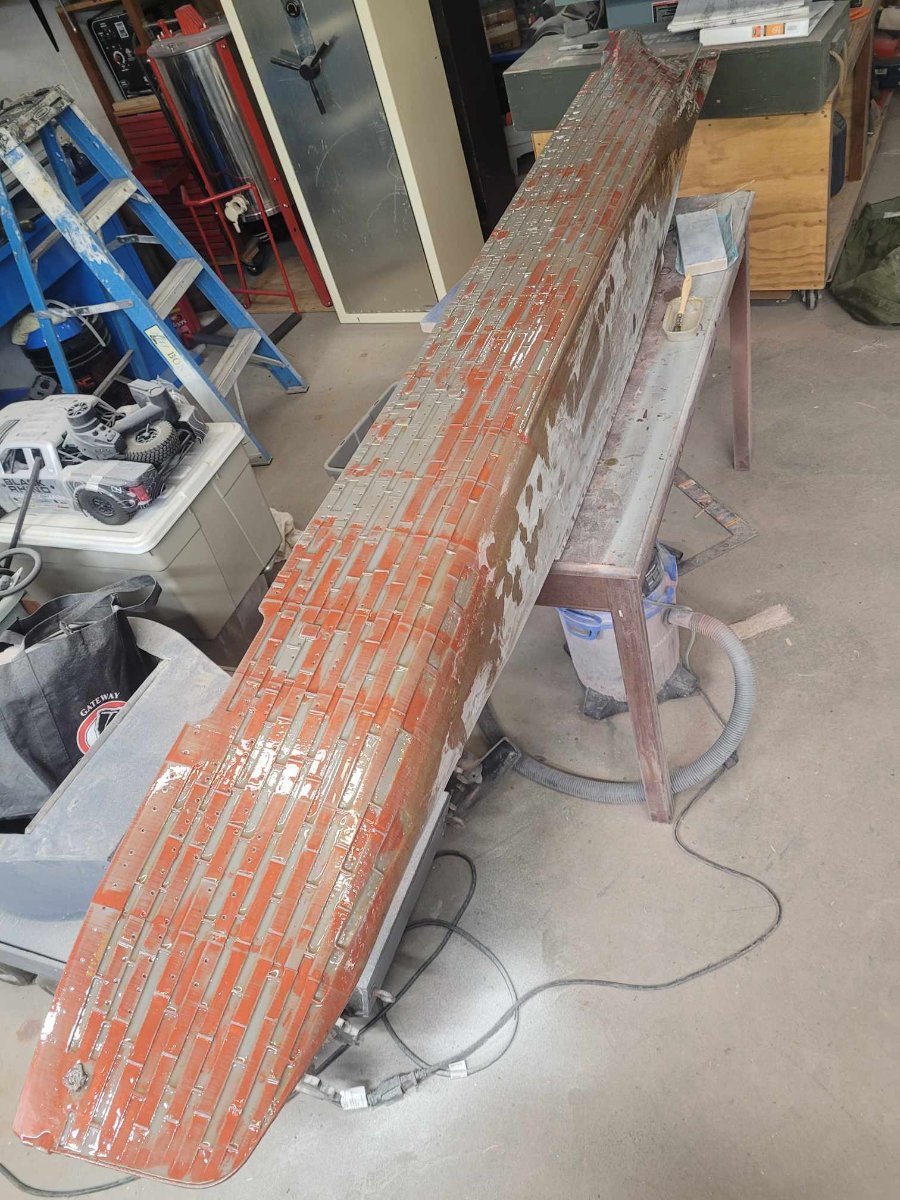
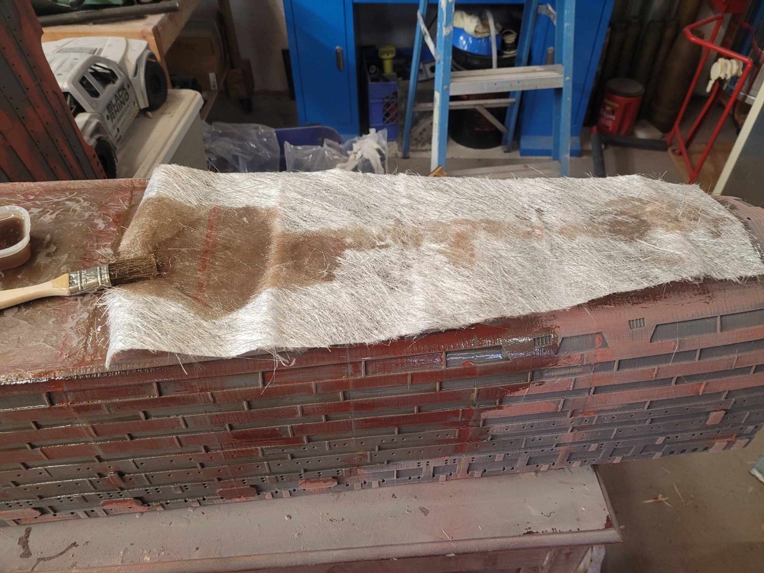
Here's how things look tonight after some putty, some fiberglass, and some more glue.
Recall, this model is destined for a pond, so it's got to be resilient. Fiberglass layers will do that...I hope.
Here we see the first layers of fiberglass mat applied. I used the mat instead of the regular weave because...well...I had some on hand and wanted to use it up as a base layer.
In this image, you can see the roughness of the base layer which you get from the fiberglass mat - the center of the keel area has now received 2 layers of resin. This is a....BIG....ship.
NS


- scrubbyj427, Valeriy V, mtaylor and 3 others
-
6


RMS Titanic by NavyShooter - 1/100 - 3D Print - Pond Float display - Halifax Public Gardens
in - Build logs for subjects built 1901 - Present Day
Posted
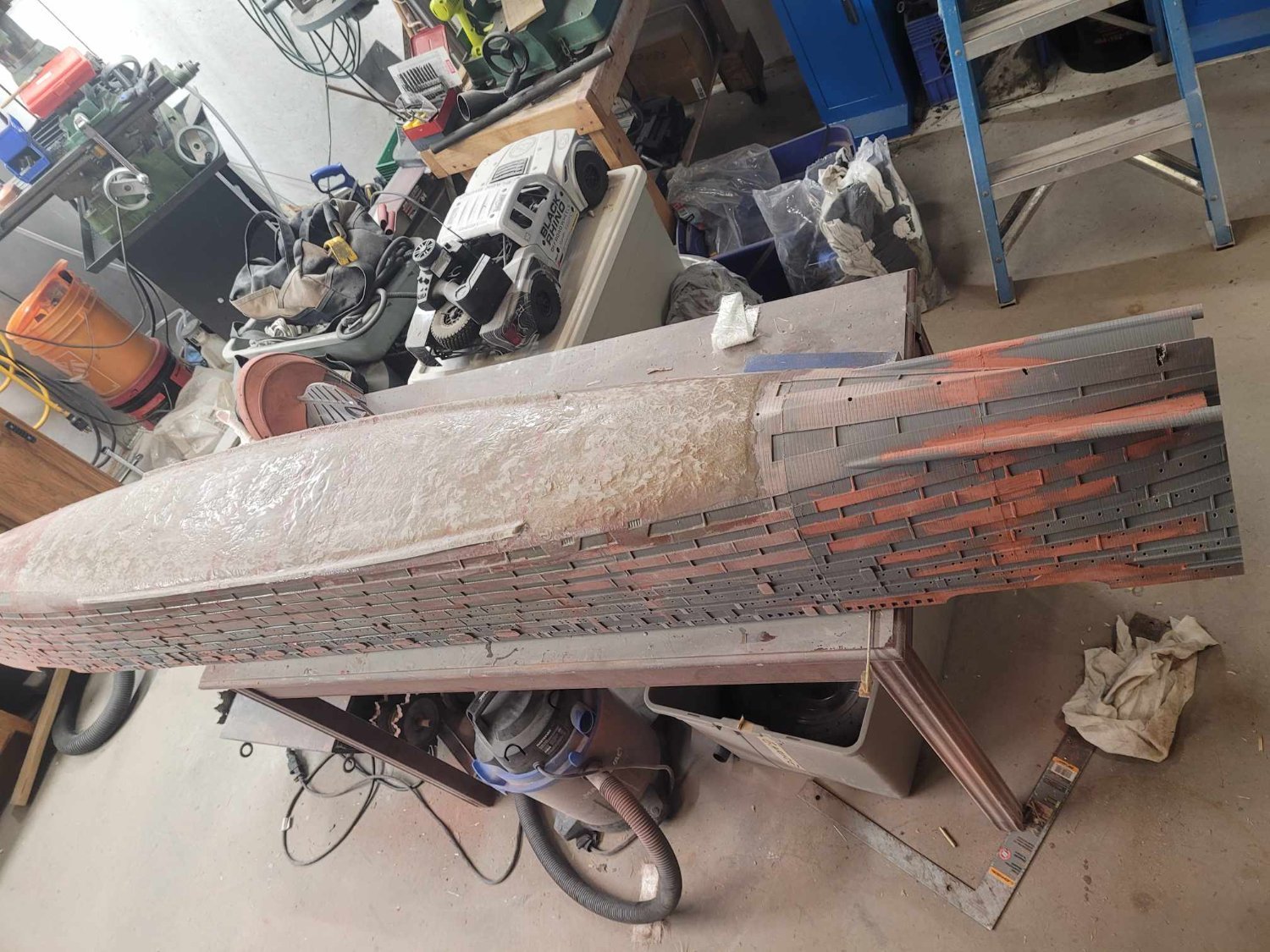
OK, so having carefully fiberglassed the keel and sealing things up nicely...now is the time where I go back and start drilling holes.
The fact that this model will likely see some rough handling over years of use means that having a full length keel strip to protect and strengthen it is a very good thing. To accomplish that, we're going with a 1" by 1/4" strip of aluminum, one on the inside, the other on the keel.
I've got the holes drilled, and if I'd been smart enough, I would have measured the length of the stainless steel screws I needed first...but I didn't, so I need to go back to the hardware store tomorrow after work. Note, I intend to have the 2nd screw hole back setup with an eye-bolt rather than a bolt, that way there's a ring to attach the anchor line to below the waterline.
I have 4 cans of fiberglass resin, and 50 pounds of lead shot. My intent is to pour the resin along the edges of the interior strip, and put a layer of lead shot in it along the length of the keel. The estimate is that it will require 200 pounds of weight to get her down to the right waterline. Putting 50 pounds of lead shot inside will help a bit I hope.