MORE HANDBOOKS ARE ON THEIR WAY! We will let you know when they get here.
×
.jpeg.882f0a147f14858c9e673da7e13d8ebe.jpeg)
RossR
-
Posts
484 -
Joined
-
Last visited
Content Type
Profiles
Forums
Gallery
Events
Everything posted by RossR
-
They aren’t separate goals, but I believe by choosing a ship like the Beagle for my first build may have slowed my skill development compared to building simpler builds like some of the Modelshipways kits. I just prioritized a kit I found more interesting. Skills still developed, just at a different pace and different order perhaps.
-
I started with HMS Beagle and my second build is the frigate Diana both from Occre. I have enjoyed hundreds of hours building these and don’t regret my choice of models. However, I have no doubt that my skill as a model builder would have been better served starting smaller. As I am a couple years into the hobby I do wonder if I went about this the right way. Decide if you primary goal is to develope skills that will result in later building your “master piece” or are you willing to sacrifice some of your skill development for a subject matter you find more interesting. I have the US Brig Syren on the shelf and I won’t start that one until I am confident my skills will do it justice. while the cost of a kit is high, the per hour cost of the hobby is incredibly low compared to my other hobby of golf. Good luck on your next build whatever you decide.
-
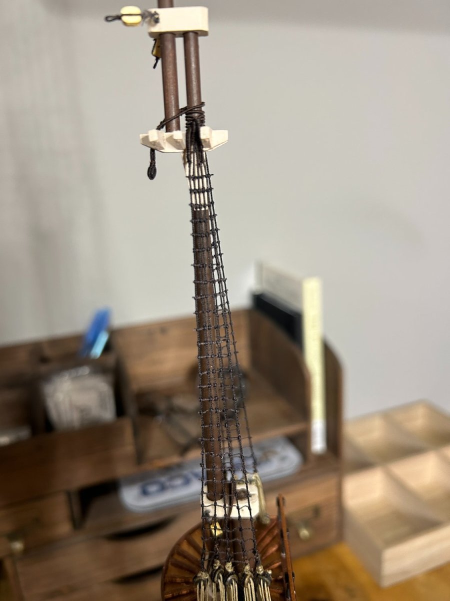
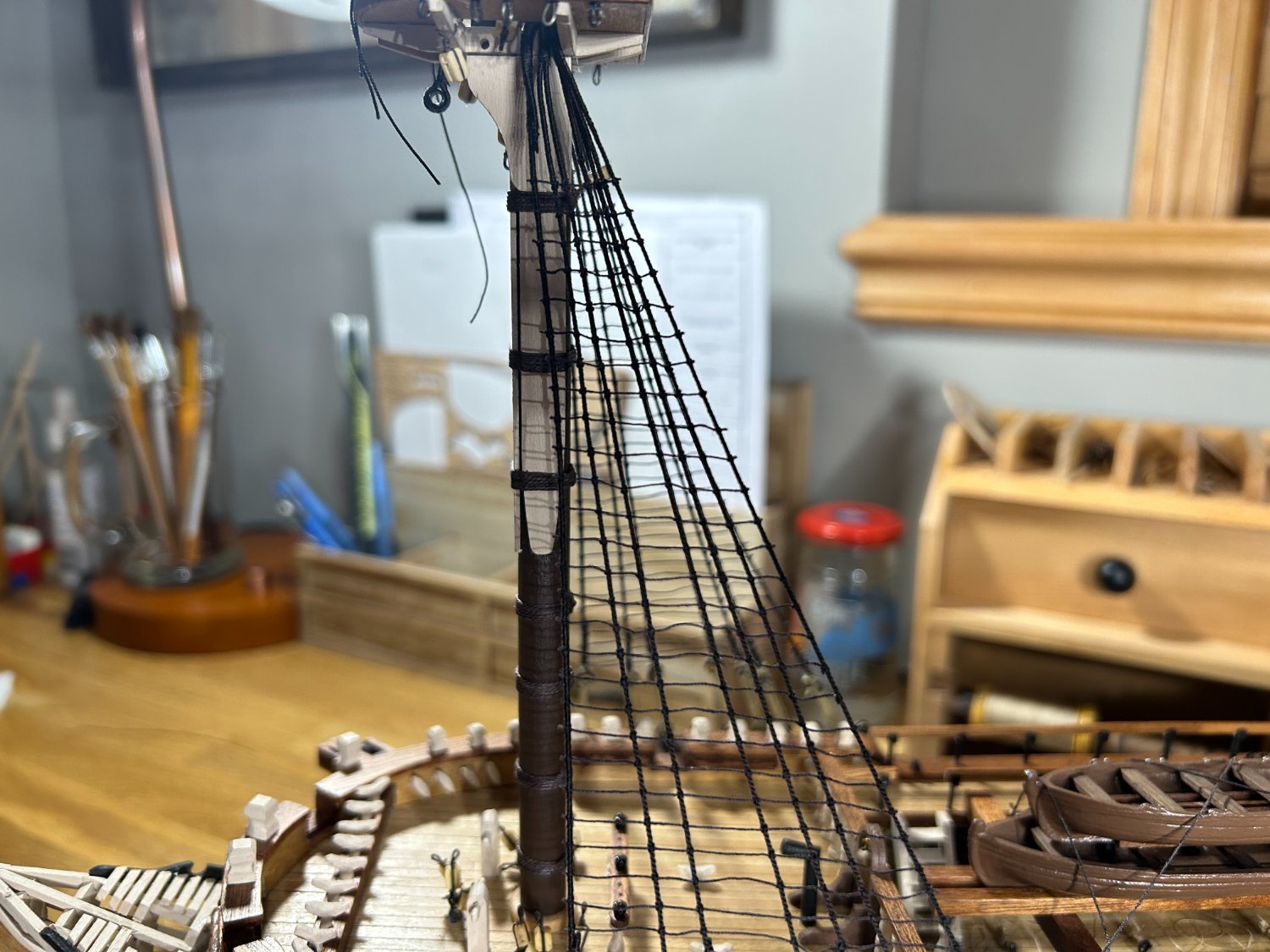
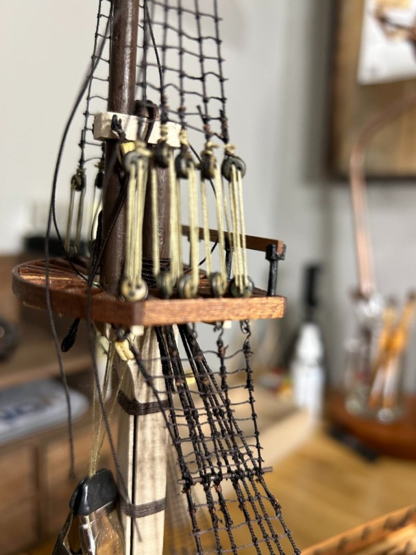
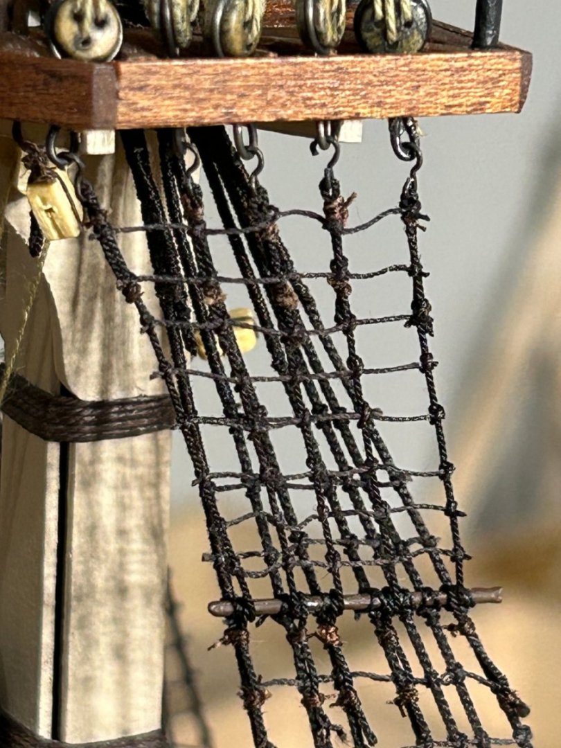
.thumb.jpeg.ffac2f8a24d212961a83eab4efb06a6c.jpeg) I have finished the top gallant shrouds on the foremast. My plan is to build each mast and then add the shrouds for that mast. After the three masts are installed with their shrouds I will add the bow sprite which I have already build and add the stays and back stays, then I will start building and adding the yards. I am pretty happy with the rigging so far. The futtock shrouds and stave just below the top gallant shrouds were tough to get tied properly. Not a lot of space to work with. Now on the the main mast. I don't think I took very many pictures when I built the fore mast, so I will try to get a few more as I build the main mast.
I have finished the top gallant shrouds on the foremast. My plan is to build each mast and then add the shrouds for that mast. After the three masts are installed with their shrouds I will add the bow sprite which I have already build and add the stays and back stays, then I will start building and adding the yards. I am pretty happy with the rigging so far. The futtock shrouds and stave just below the top gallant shrouds were tough to get tied properly. Not a lot of space to work with. Now on the the main mast. I don't think I took very many pictures when I built the fore mast, so I will try to get a few more as I build the main mast.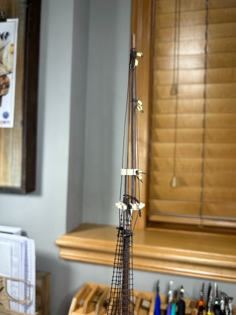
- 142 replies
-
- 10
-

-
Yes. There is a stave.
-
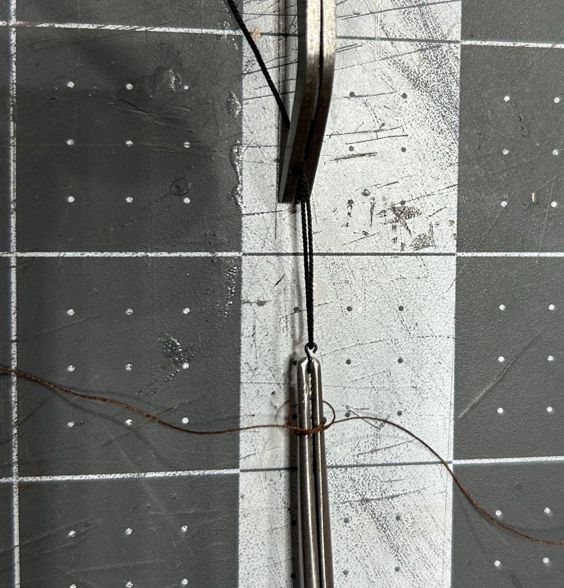
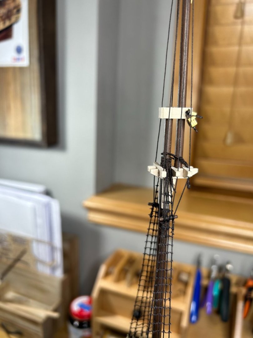
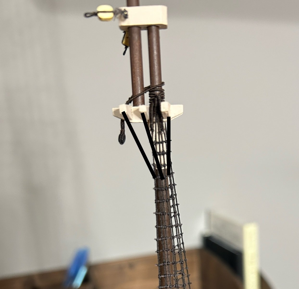
Thanks for the reply. I think you might be describing the futtock shrouds lower on the mast. I am talking about the ones right below the cross tree where the top mast ends and the top gallant mast starts. See the ones drawn onto the photo below. Perhaps I am using the wrong terminology.

-
Does anyone know if the futtock shrouds between the cross tree and the top mast shrouds should have ratlines on them? I am building a late 18th century Spanish frigate.
-
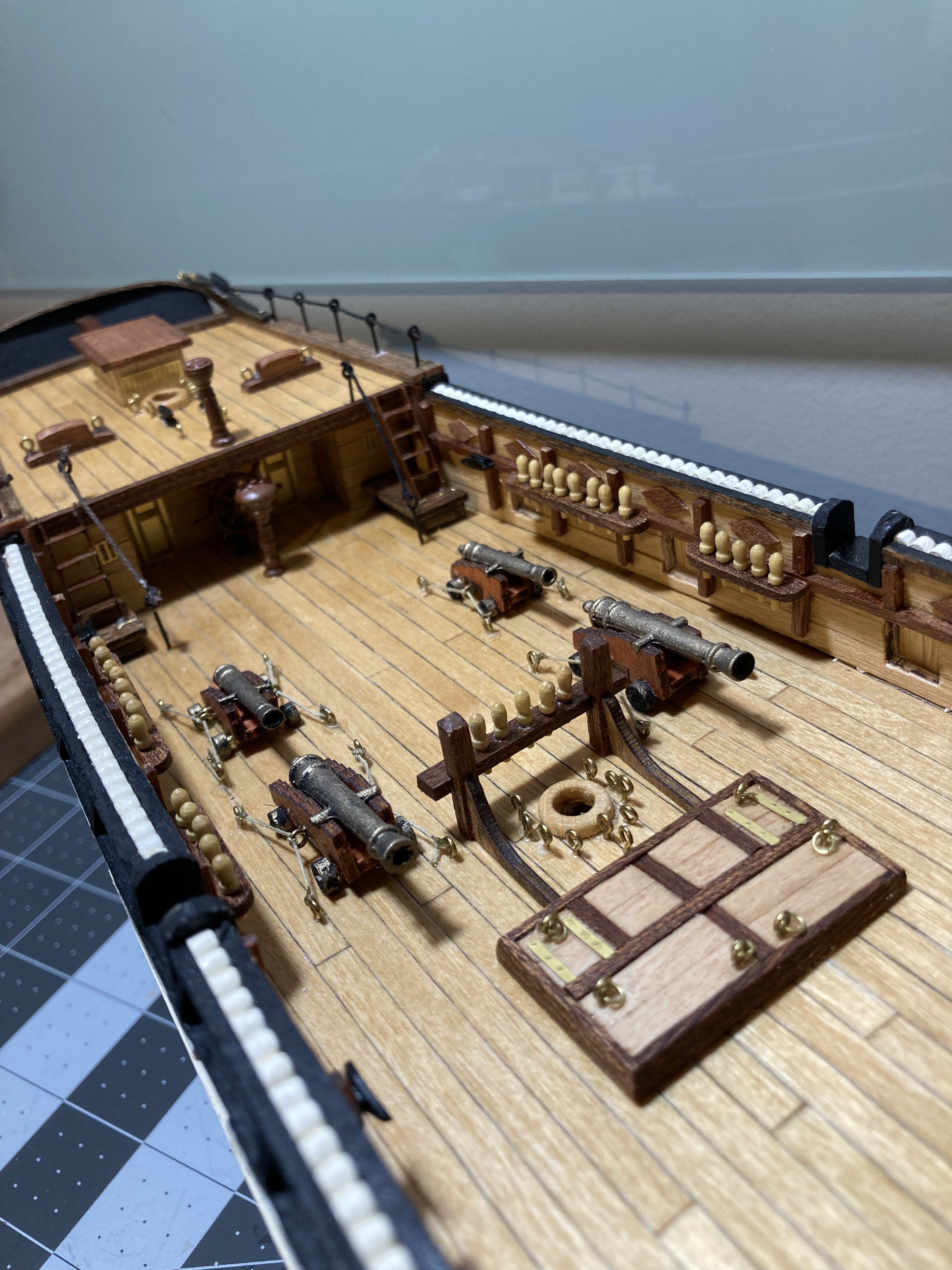
Your gun ports look fantastic. Great job.
-
Question about Symbol on building mast
RossR replied to ChuckP's topic in Masting, rigging and sails
I think Broach Boating is on the right track. Your image is plan A and the line labeled B will correspond to a line on plan B that shows the point that the plans overlap. -
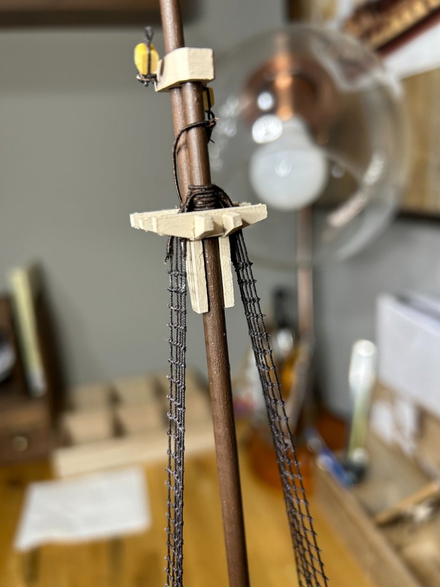
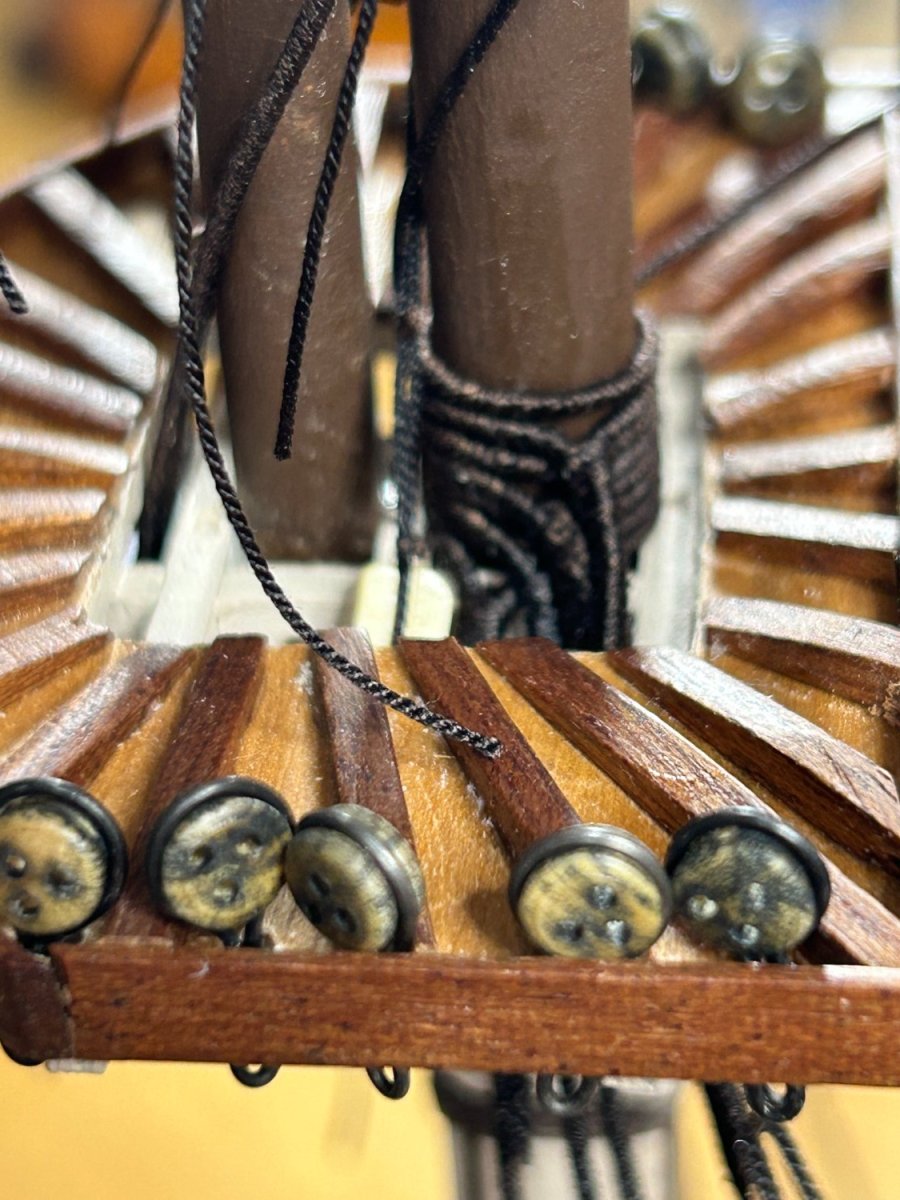
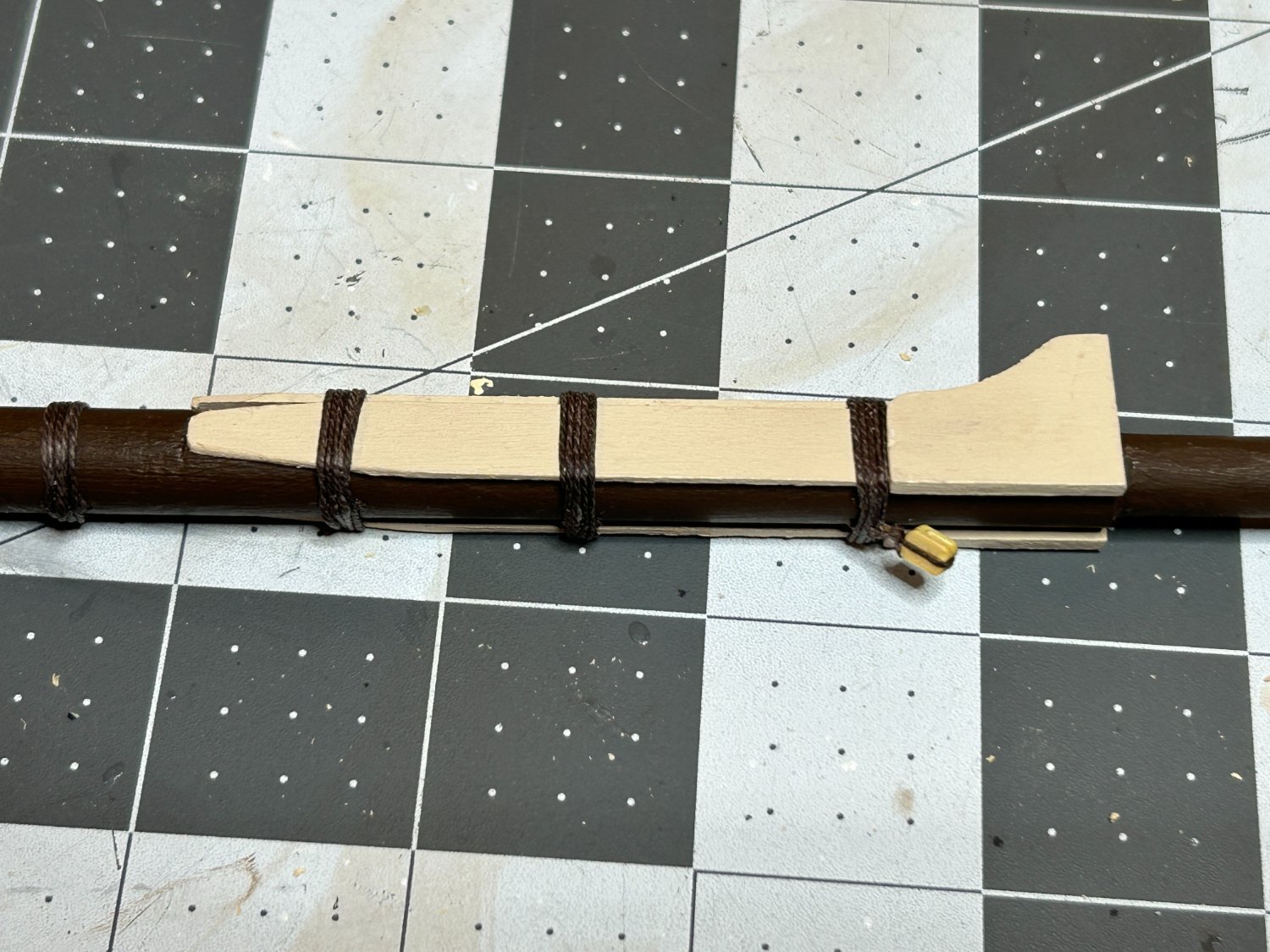
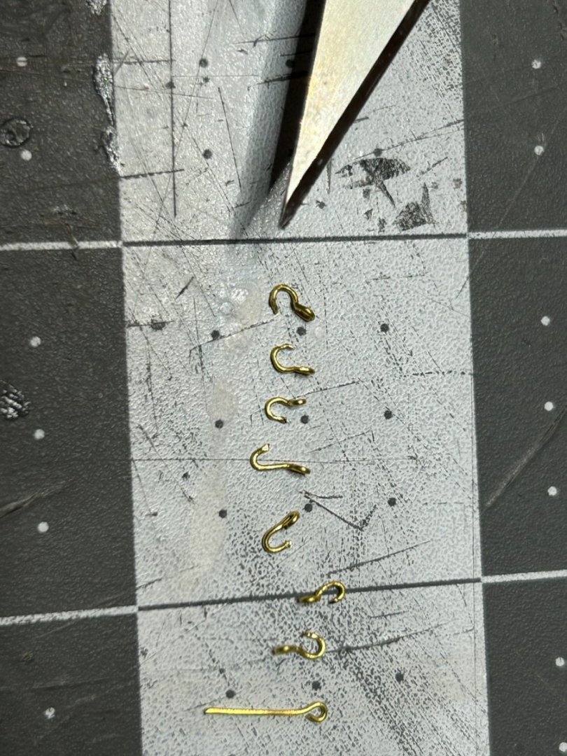
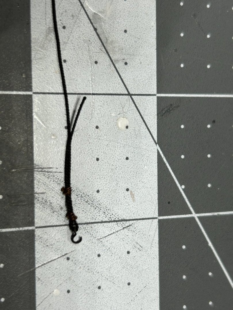
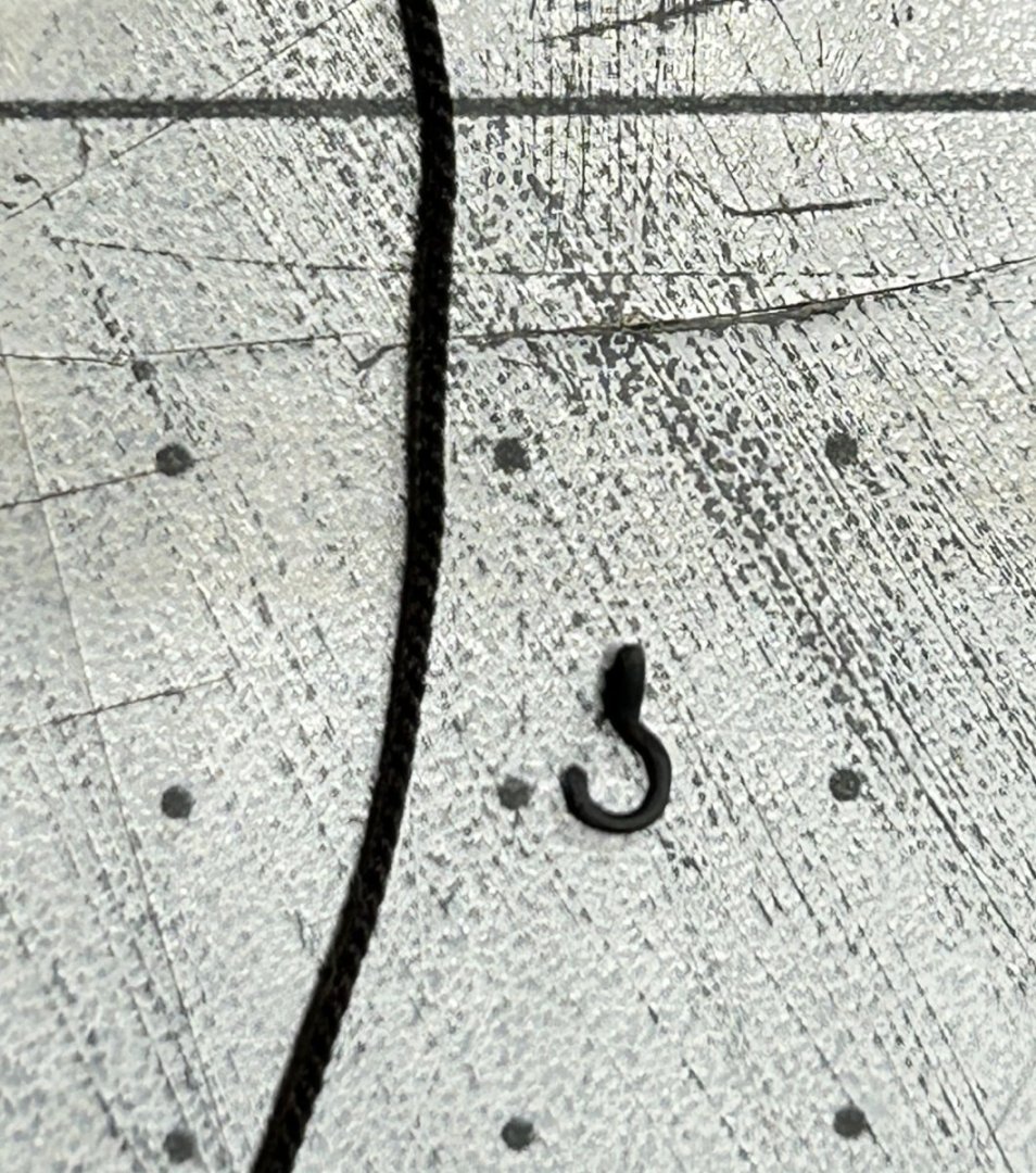
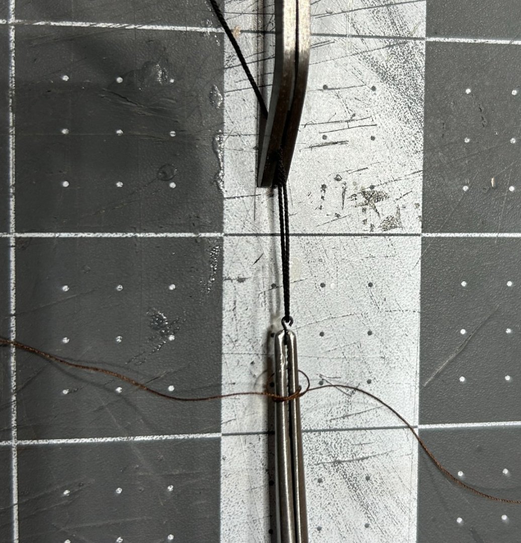
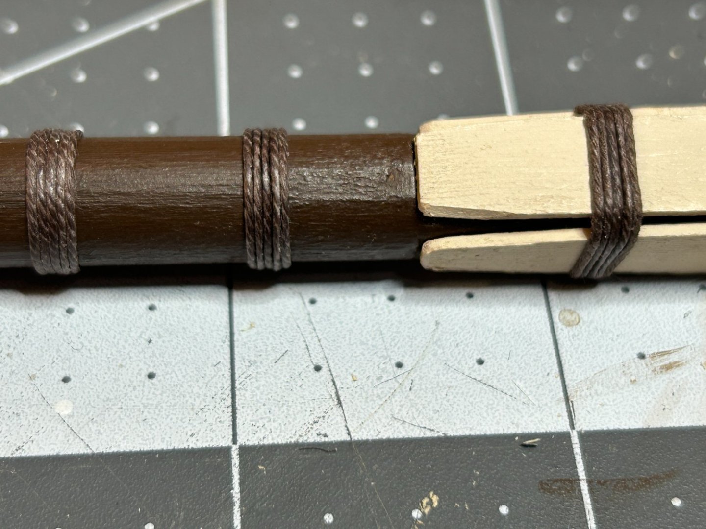
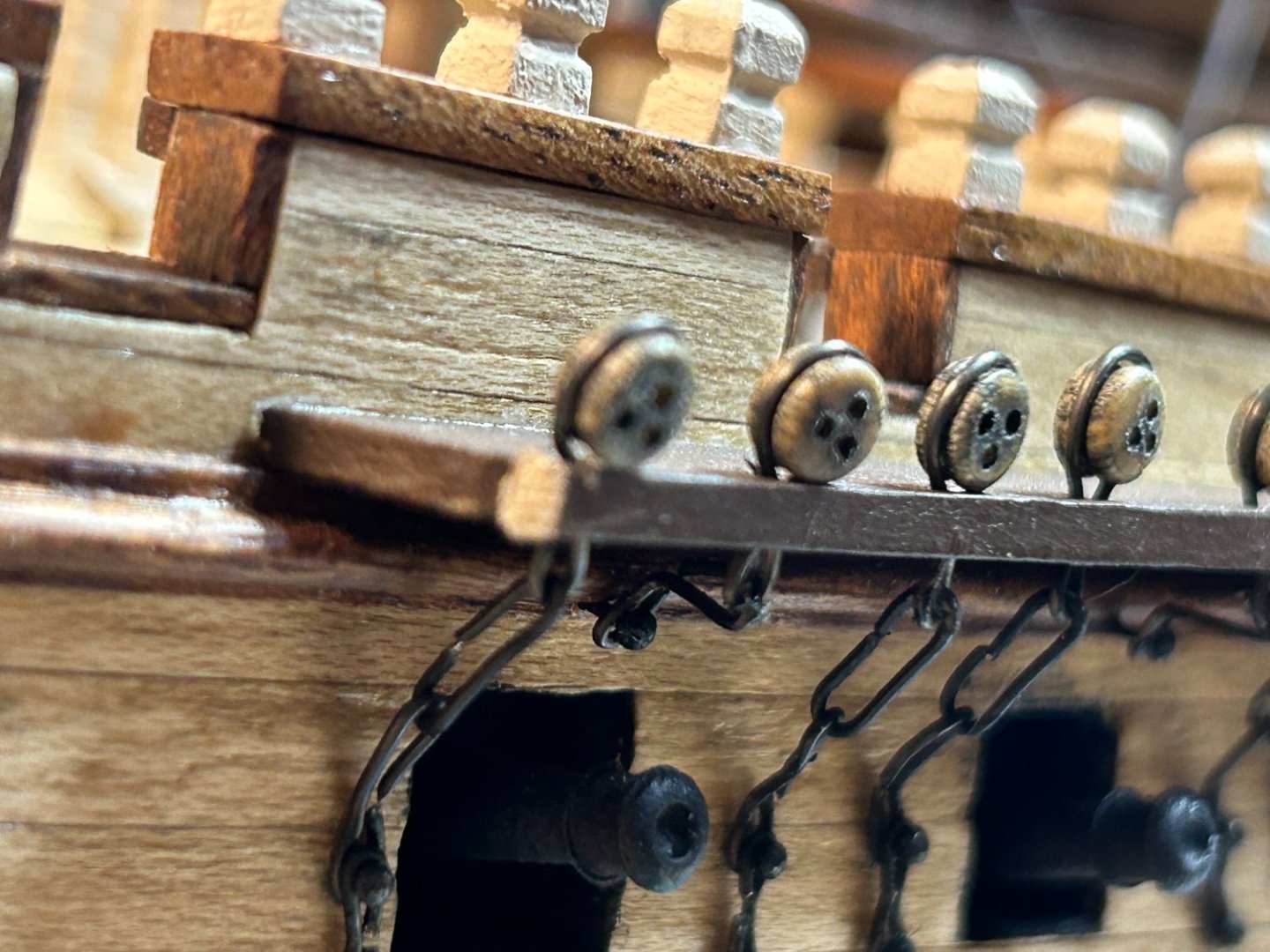
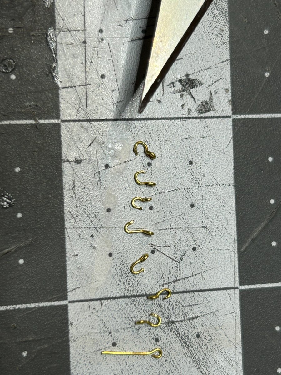
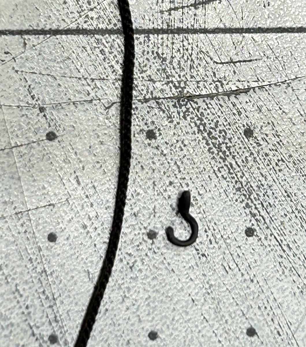
Here is my latest update. The first thing I did was create the hooks that attach the futtock shrouds to the deadeye strops. I made these out of some small eyebolts. They measure about 1/8th of an inch. These were the first items that I blackened with Birchwood Casey Brass Black. I soaked the parts overnight in alcohol to remove any oils from handling. I am not sure how long the soak needed to be, but I left the parts over night just to be sure. After a rinse in distilled water and allowing the items to dry I soaked them for about 30 minutes in white vinegar. Another rinse in distilled water and then into the Birchwood Casey solution. A minute or so in the solution and the items turned a nice uniform dark grey / black color. I lashed the .018 inch diameter line to the hooks using a technique similiar to one that Glenn-UK discussed in his Indefatagable build log using alternating overhand knots. The futtock stave is made from a piece of brass rod that was painted brown. I lashed that to the shrouds using criss-crossing overhand knots after struggling to tie a clove hitch to secure the stave in the tight space. I have the top mast shrouds added also. These are the same .018 diameter line used on the futtock shrouds. The rate lines have been added also. This was the cross tree that I had to rebuild from scratch after rolling over the original one with my chair. Next up are the top gallant shrouds. After those are installed I will shift away from the rigging to build the main mast and the channels and chain plate associated with the main mast. I enjoy the rigging, but when I built my first ship I have to admit that after building all the masts and yards and then doing all the rigging, both steps got a little tedious. This time I am breaking up both steps a little bit. My plan is to add each mast and the shrouds associated with that mast, when all the masts are up I will add the stays, backstays, and all the running rigging.
.thumb.JPG.31b6ac2dd6288c832d4e06553be2811e.JPG)


- 142 replies
-
- 11
-
-
Do you mind if I ask what kind of wax did you use?
-
As always, your work is impressive. I always look forward to your updates.
-
Thanks for the info. I also found ones sold by Rockler Woodworking that are labeled with steel wool grade equivalents.
-
i am going to give Scotch Brite a try. Love the finish but hate the mess with steel wool. Do you know if the fine Scotch Brite pads available at box box home improvement stores?
-
I have had good luck with a two pound cut. I get a flat finish with two coats and a rubbing down with steel wool after each coat. Steel wool is messy, but I like the finish it leaves. I always head to the garage or out side when I use it.
-
A new angle in precision sanding
RossR replied to Arcticbeaver's topic in Modeling tools and Workshop Equipment
The ultimation tools are on my wish list. I wish it had positive stops for common angles though. -
Very impressed with your jig for drilling the hole for the bow sprit. I find that step very nerve racking.
-
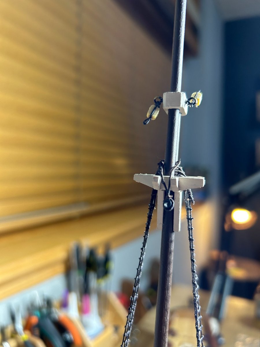
I have completed the ratlines on the lower shrouds. I used .008 inch diameter rope from Syren. The ratlines are place 4mm apart from each other. At this scale that works out the a little over 13" spacing. There are a total of 30 ratlines per side. With 7 shrouds per side, that works out to 420 clove hitches. I now need to add the futtock stave and the futtock shrouds. This will be my first model with a futtock stave. I am looking forward to adding this feature. My HMS Beagle had the futtock shrouds pass through the lower shrouds and attached directly to the lower mast. I am hoping to have this work done by the end of the weekend.

-
I am very impressed with your planking. I hope I can do as well someday. Can't wait to see the rest of you build.
-
I find myself more and more often considering stopping posting on Model Ship World. A few weeks ago I encourage a member to continue despite some pretty negative comments by another user. The offending post has been removed, but not after I think it was actually "liked" by one of the moderators. Yesterday I think less that constructive language was used to describe the Occre HMS Victory model kit. This kit isn't for everyone, it is fair to point out historically inaccuracies, or to challenge whether it is truly a plank on frame model or some thing else. As we have recently heard from Chuck, a true plank on frame kit can be very expensive. If this is a something that gives someone a "taste" of plank on frame at a lower cost than full on plank on frame, maybe that is ok and maybe someone will be inspired to do a full plank on frame model after building this kit. And if some of us are not able or interested in investing the time and sometimes money to do extensive research on a particular ship, that should be OK. Please keep helping those that what more information about the ships they are building, but no need to mock those that are simply building a kit to impress their friends and neighbors. 45,000 members, but how many have a build log in the last year or two. I am not sure I would give the same advice I gave a few weeks ago about continuing to post on the site if I was giving the advice today.
- 56 replies
-
- 17
-
-
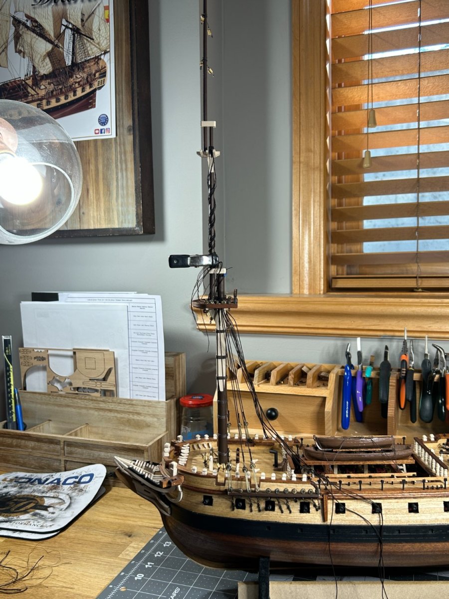
I have competed building and installing the foremast and started the standing rigging. The Occre rigging plan included two diameters of line for the standing rigging. I upgraded the ropes to some that I purchased from Syren and will modify the rigging plan to include about 5 different diameters. The fore shrouds are 0.030 inch diameter and I served the entire length of the first shroud and served the portion of the other shrouds that wrap around the mast. My ship has an odd number of shrouds. There was some recent discussion on another build log about whether the shroud that isn't part of a pair should be installed first or last. I have chosen to install mine first. I don't know what the historically correct way would be on a Spanish frigate, but this is the way I chose to go. The fore top mast shrouds and the fore top gallant shrouds will be 0.018 inch ropes along with the backstays. The ratlines will be 0.008 rope. Next up will be adding the ratlines. Then the futtock stave and shrouds.


-
This looks great. I am amazed at how fast you got this far. I would be lucky to get a few planks a week done.
-
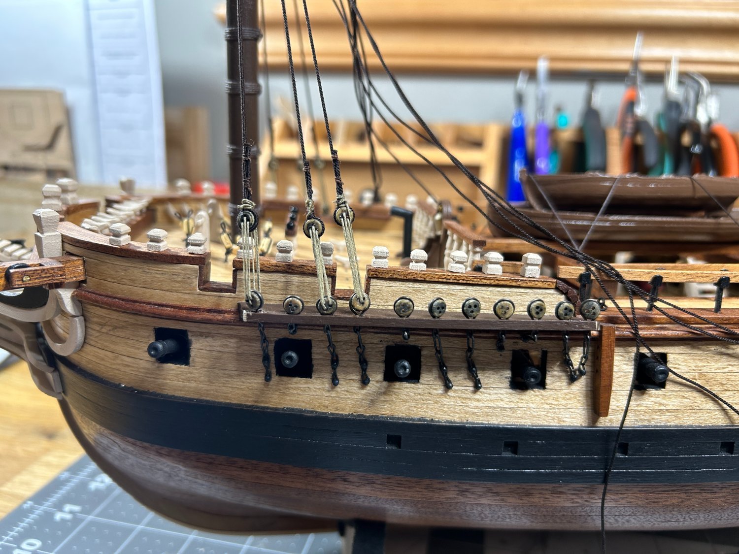
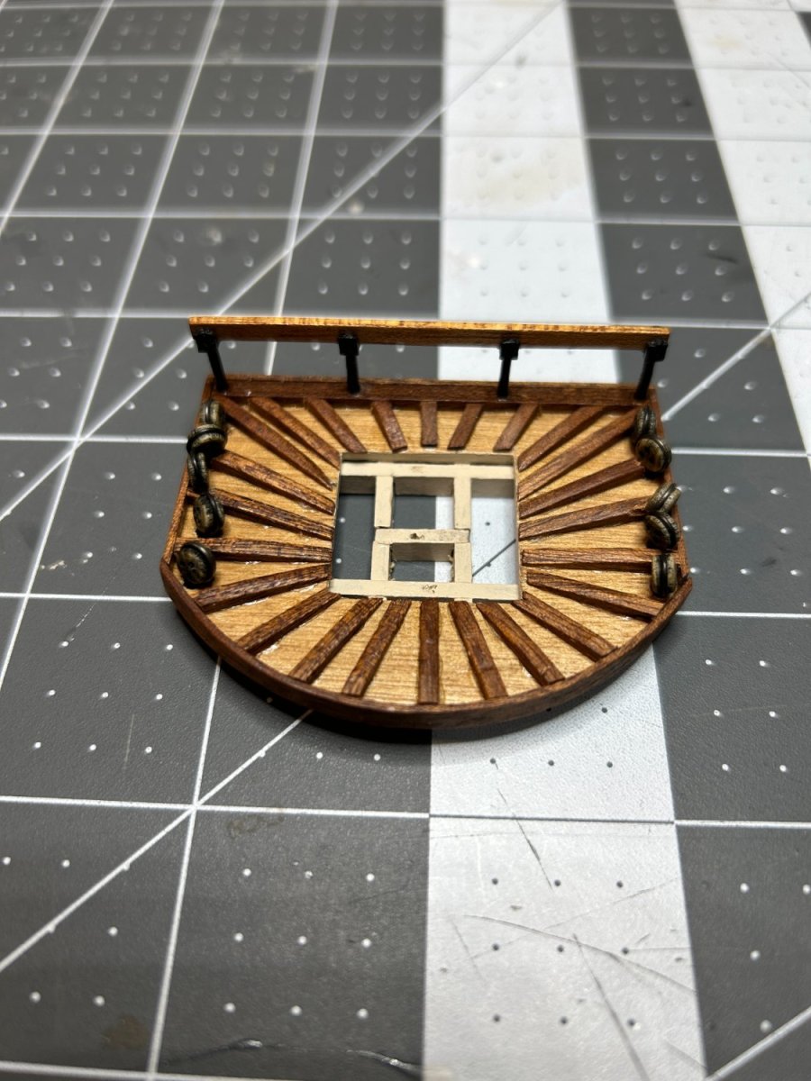
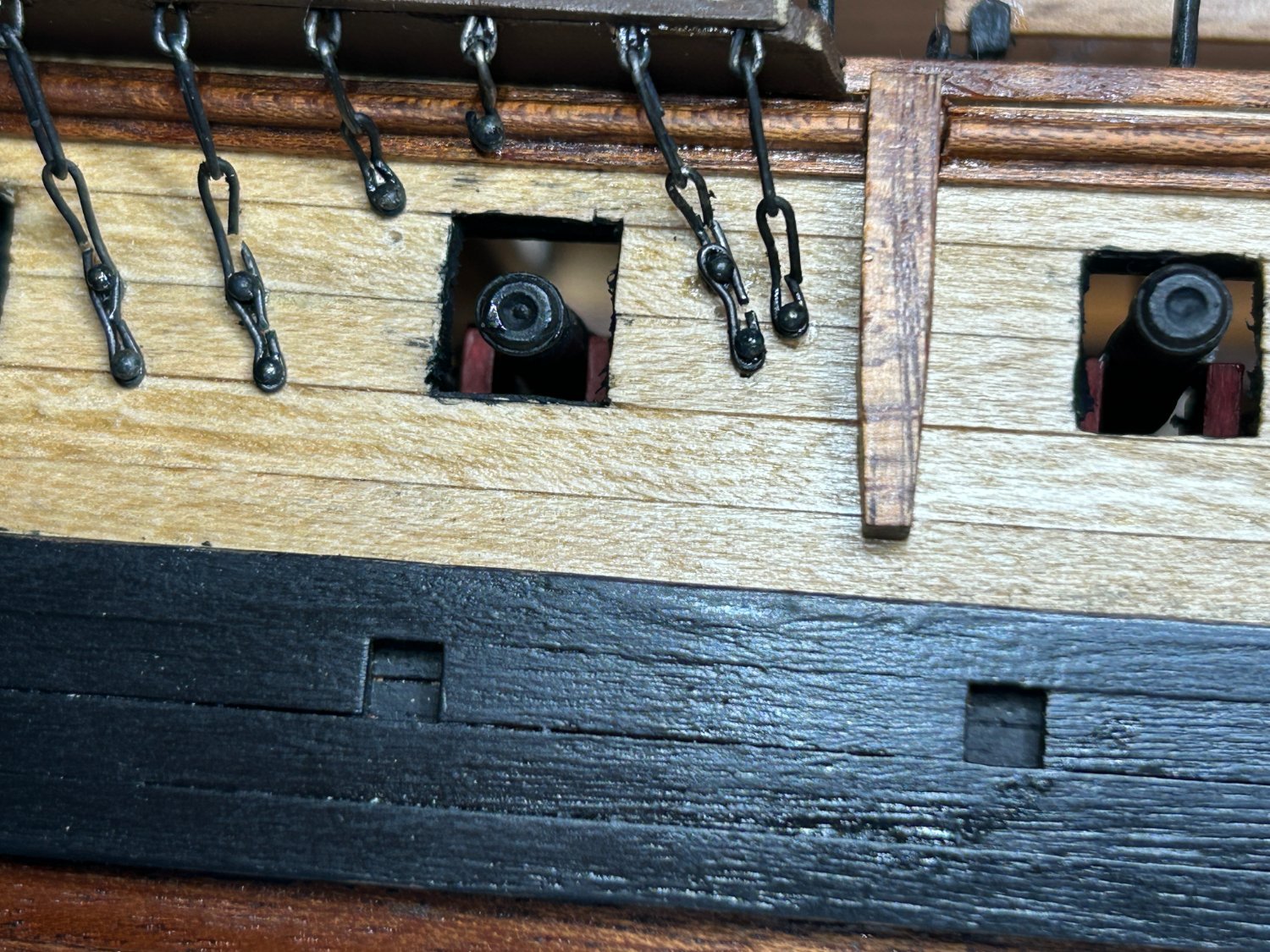
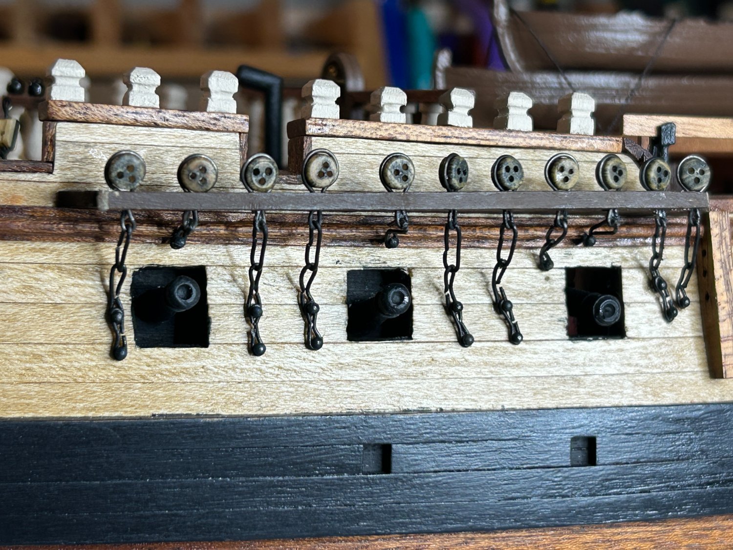
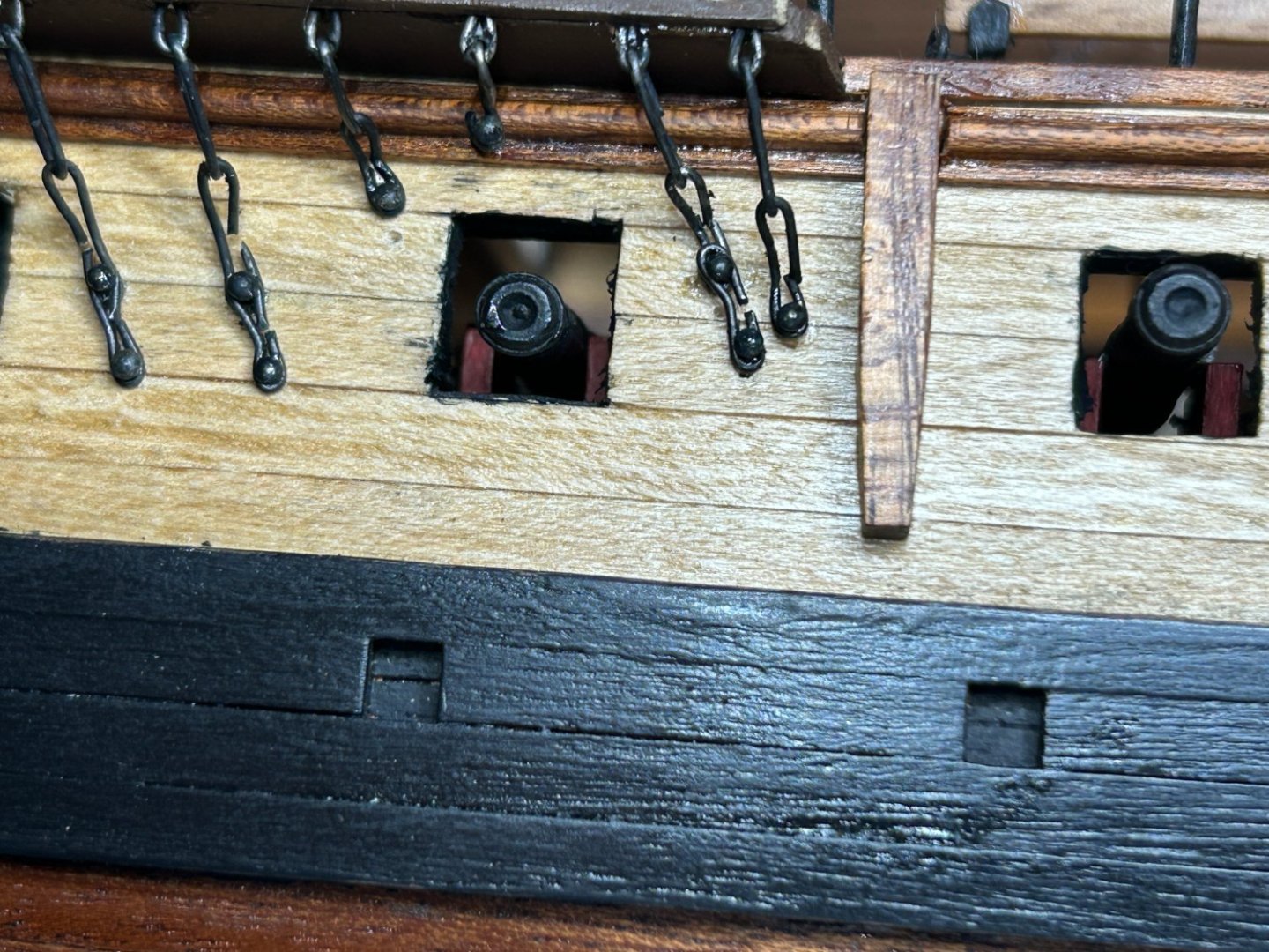
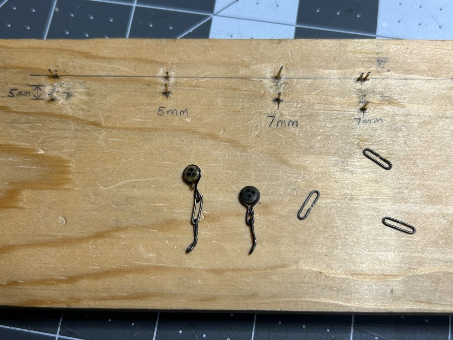
I have made some progress on the chain plate recently. I used the directions for the US Brig Syren as a basis for making the chain plate for this model. I experimented a little with the lengths for the various segments. I used black annealed wire to make the chain plate. I built the jig below to create the various segments. I dry fit the foremast assembly so I could match the angle for each of the shrouds and backstays for each of the chain plate assemblies. I have waited to add the gun port frames and hatches because I don't trust myself not to break the open hatches off. I will add those at the very end. Last but not least. Happy Veterans Day (or Remembrance Day to members in the UK) to all those who serve. Thank you.

-
I like what you left in the topic. Thanks.
-
Thanks for sharing you thought process on this step. I am at a similar point in my Frigate Diana build and you validated some of my decisions. I am fabricating my chain plate out of black annealed wire as my kit suggested using a single strand of brass wire. I didn’t like that approach. spent quite a bit of time making different sized pieces trying to find the right combination of components to fit right. Your work is fantastic. I hope one day my work will look this good.
- 587 replies
-
- 2
-

-
-
- Indefatigable
- Vanguard Models
- (and 1 more)
-
I like your NRG Half Hull hanging in the background of your photos. Did you do a build log of that project?


.JPG.08a3d0ea87d80effcaf09caeae7fbd55.JPG)