MORE HANDBOOKS ARE ON THEIR WAY! We will let you know when they get here.
×


Javelin
-
Posts
580 -
Joined
-
Last visited
Content Type
Profiles
Forums
Gallery
Events
Everything posted by Javelin
-
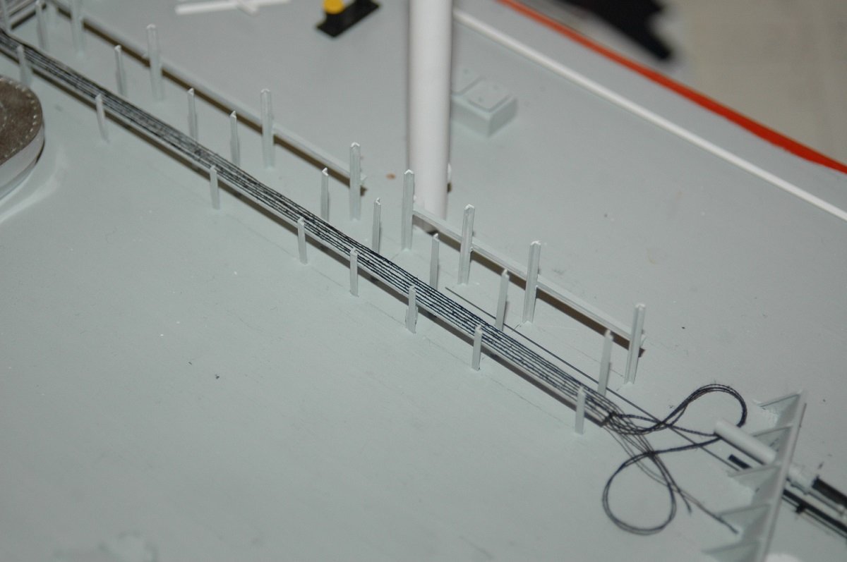
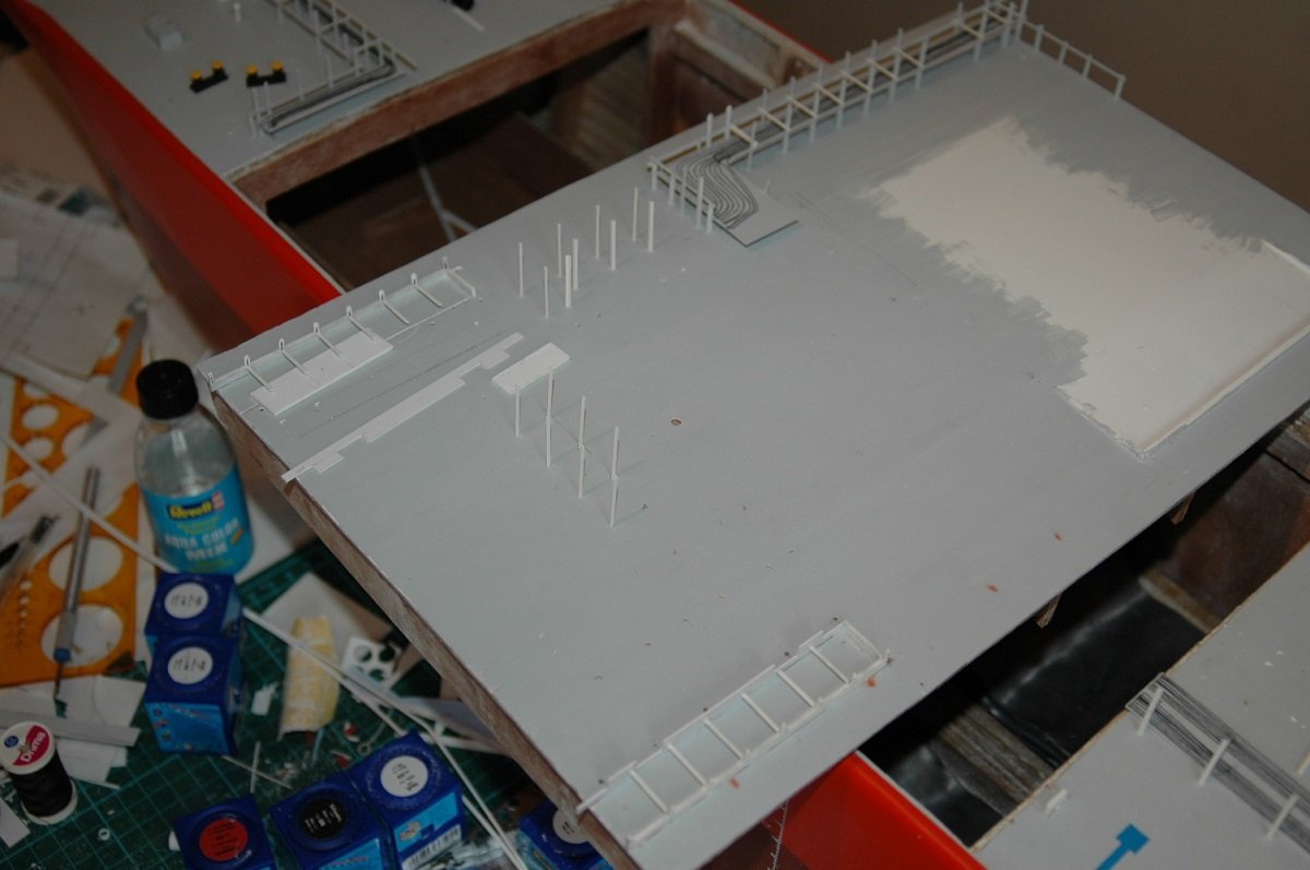
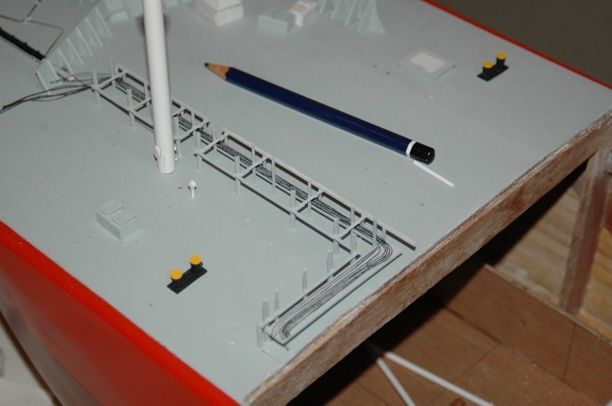
 And some more detailing. Start of the pipe racks on deck. Unfortunately they didn't use any pre-assemblies or standardized things yet. All the supports seem to be just put wherever they had to be put. I tried to replicate it as correct as possible, based on all the pictures I have. Then the first thing was the lower tier on these racks. Generally those are electrical cables and hydraulics, I decided to simplify that a bit by using a thin plate, which is actually there on the real thing as well, and put sewing thread on it to represent those cables. It would look a bit empty if I didn't do that. Here you see the "lid" of cargo tank 2 at a 90° angle on top of the hull. Part of the manifold drip trays are extending over the edge. Back then it seemed a good idea to camouflage that seam a bit, by having as much equipment overlapping it as possible. Nowadays I think that was a stupid plan. Things hamper from time to time when removing or installing the hatch. This sometimes results in damage or tearing off parts. You also see the ballast tank entry hatches appearing around the vessel. As mentioned I'm going inside out and bottom up. The Vent mast, to release overpressure from the tanks in case of emergencies, is just temporarily there. This is to line up things, but I keep it removable, so that it doesn't hamper any detailing work afterwards.
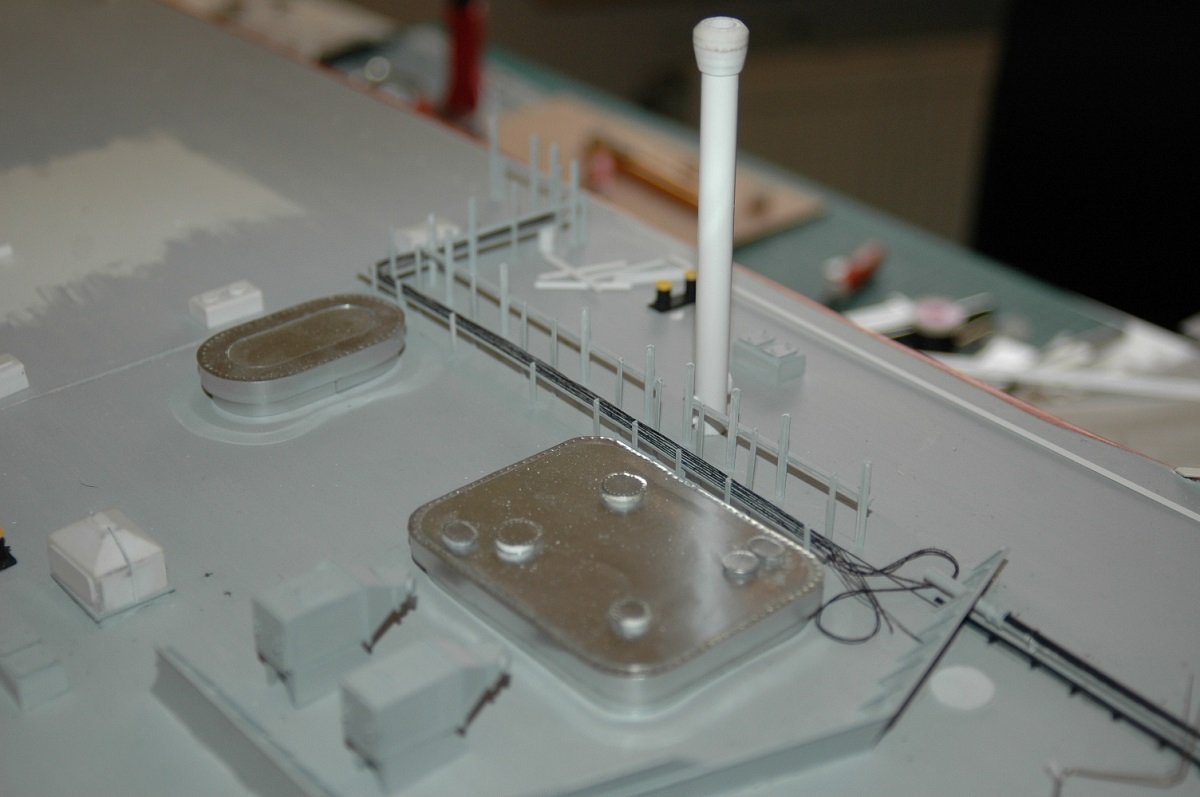
-
Just found this. Great idea, but did the bulb blow yet?
-
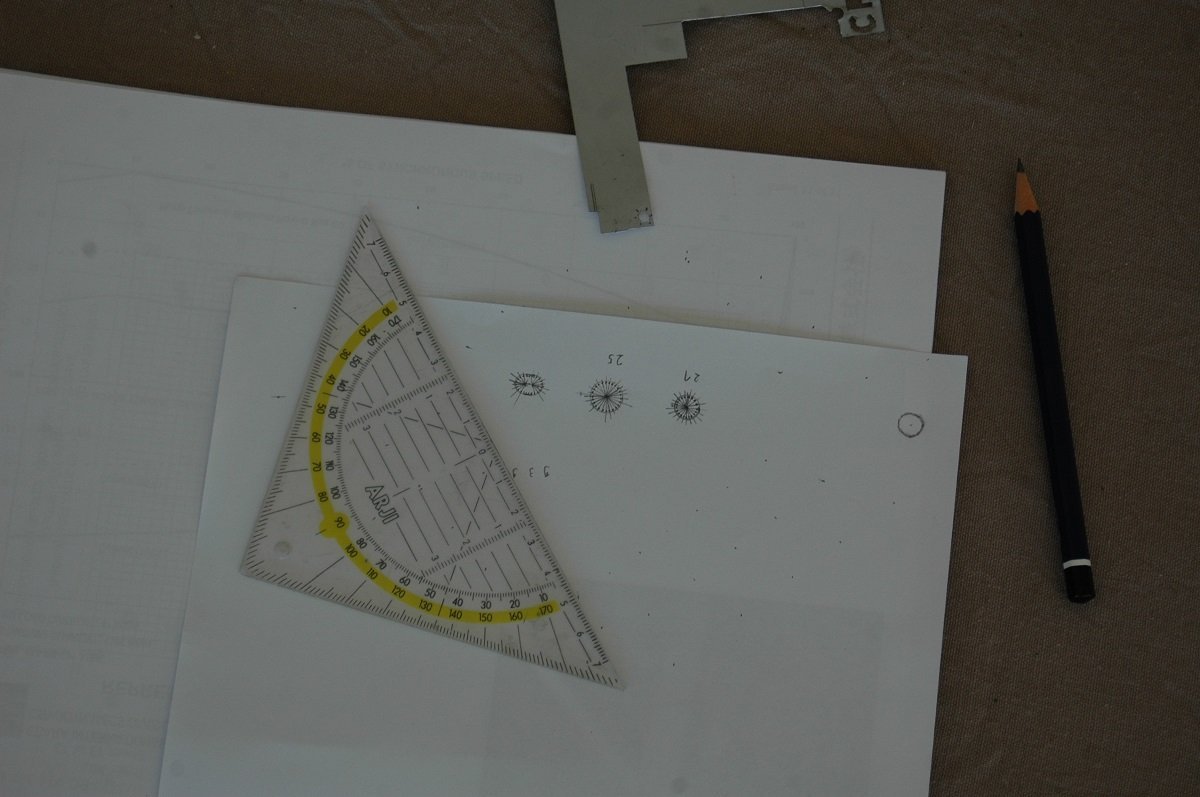
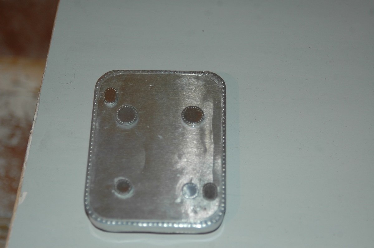
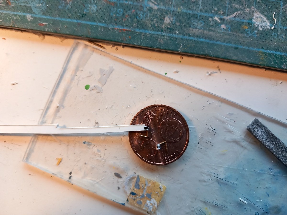
I used the the page in the first picture with the marked bolts as a template. I then overlaid it on the litho sheet. The bolts were then individually punched with a sewing needle through the paper. Only then I cut out the hatch. Litho is also quite easy to file, so you can file around the edge of the hatch to have it nicely centered around the bolts. The paper can be reused for more hatches. I do believe that at a later stage I drew some in Paint, sized and printed the templates.
-
perhaps not a bad idea to put some kind of stopper on the hinging parts, so you can pull the hulls apart till they reach that mechanical stop and up perfectly parallel? Not sure if it's required, but I hate to think that they end up not being parallel or one a bit more ahead of the other. As you know it's a mess when trying to work with two hands through a bottle neck. Anyway, an inventive and interesting way of construction.
- 174 replies
-
- 5
-

-

-
- Waa Kaulua
- bottle
- (and 1 more)
-
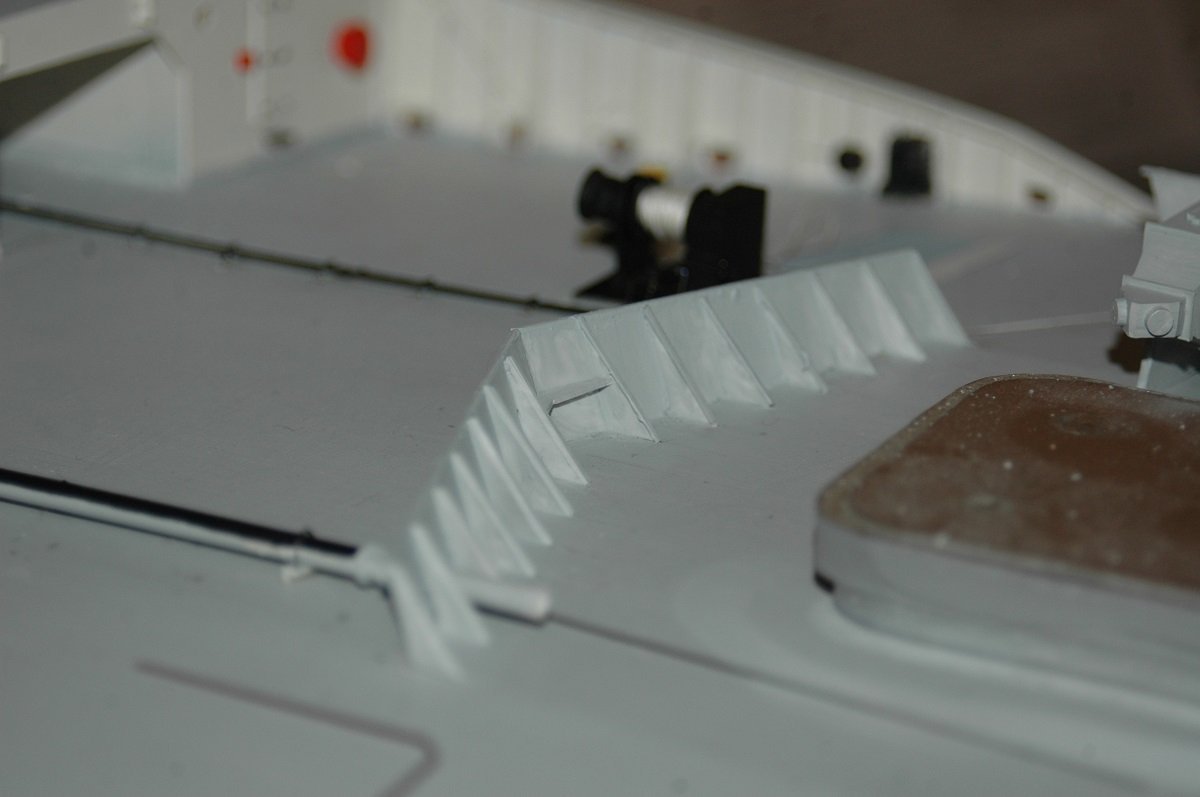
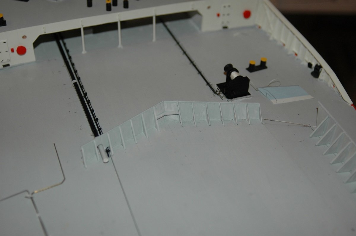
Thanks Keith, is that judging with your good eye or the bad one? 😁 As mentioned in the beginning, you can fix everything, it just took much longer than it probably should have. Next going aft was the wave breaker on the main deck forward. As you can see there was an "original design" and then some extension on starboard to protect the ventilation fans. A lot of dry fitting to get everything arranged. Those ventilation fans are still not glued into place. I still need to do some work on the center part and I want to avoid resting my hands on anything more outward. And my very old-school way of putting bolts on steel hatches. And yes, even the amount of bolts is correct.
-
Glad the surgery went well. Hopefully the recovery is speedy. Good to see you can do something on this handsome vessel in the meantime!
-
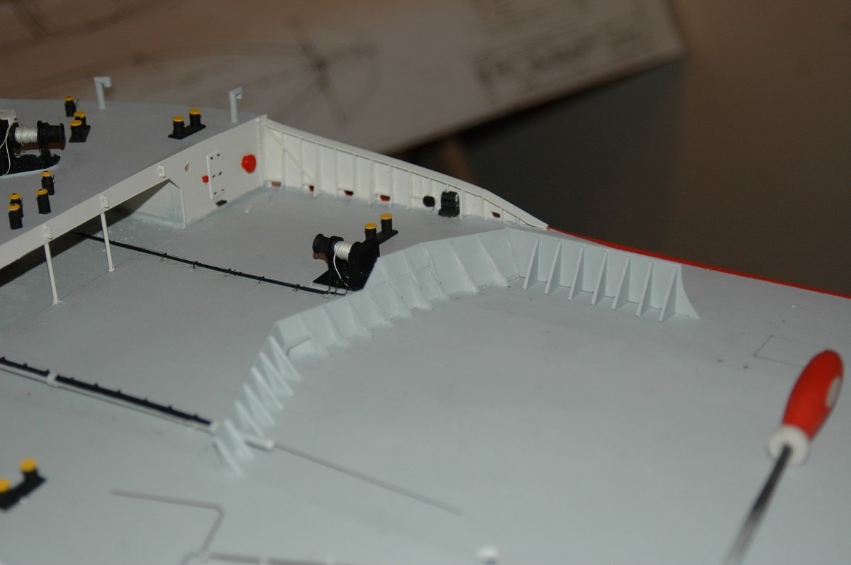
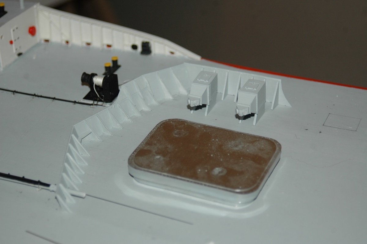
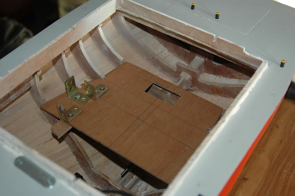
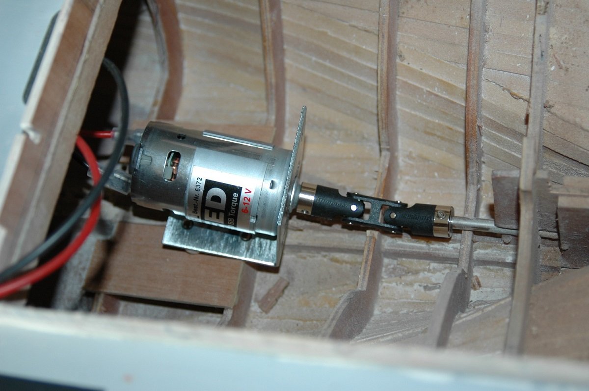
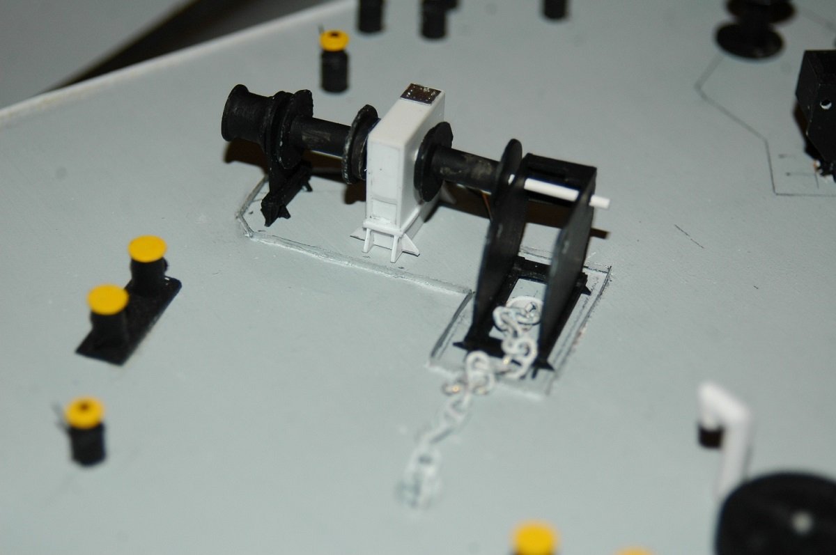
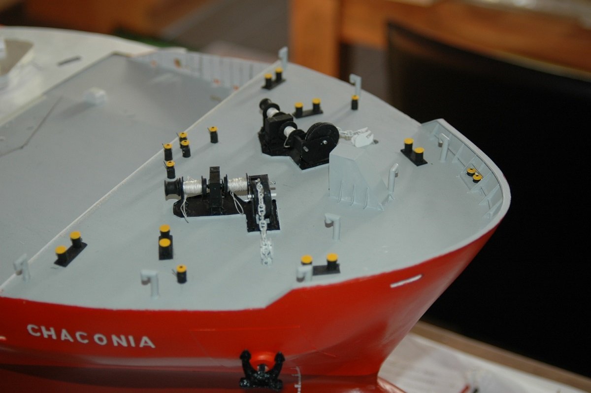
And here is the access hatch aft, underneath the accommodation block. On the bottom is the motor and then I made a level on top for the radio receiver and ESC. I don't think I left the motor like this, I think it's aligned better, but I'd have to check. Haven't looked at that for a while. You can see a small metal plate in front of the access hatch. This is part of a door magnet system, the other part is glued inside the accommodation block, it keeps it nicely in plate. Also the accommodation block fits nicely around the coaming to stay in position. For releasing the magnet, I tilt the back of the accommodation up and hinge in on the front edge, which releases the magnet from the plate. And slowly made my way aft from the forecastle. You see the mooring winch in place and the outline for the wavebreaker that protects the forward tank equipment. Close-up of the detailing. A spare anchor seat, although I don't think she ever carried a spare anchor. The mooring winch hydraulic lines (yes, I know, I probably overdid that...🤪) Currently I'm trying to put 2 parts per day on this ship. There's an enormous amount of stuff to be placed. Which is why I stopped back then. However, by forcing myself to build and/or put 2 parts on the ship each day, I'll slowly make my way. Some parts take a long time to build, some less, however when time is too limited, I shift from a larger, more complicated piece, to a smaller one that's manageable within my available time. In the end, all parts have to be made after all...
-
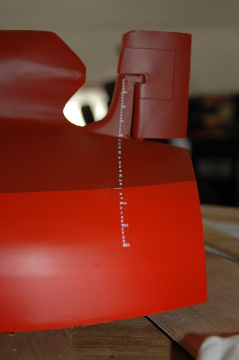
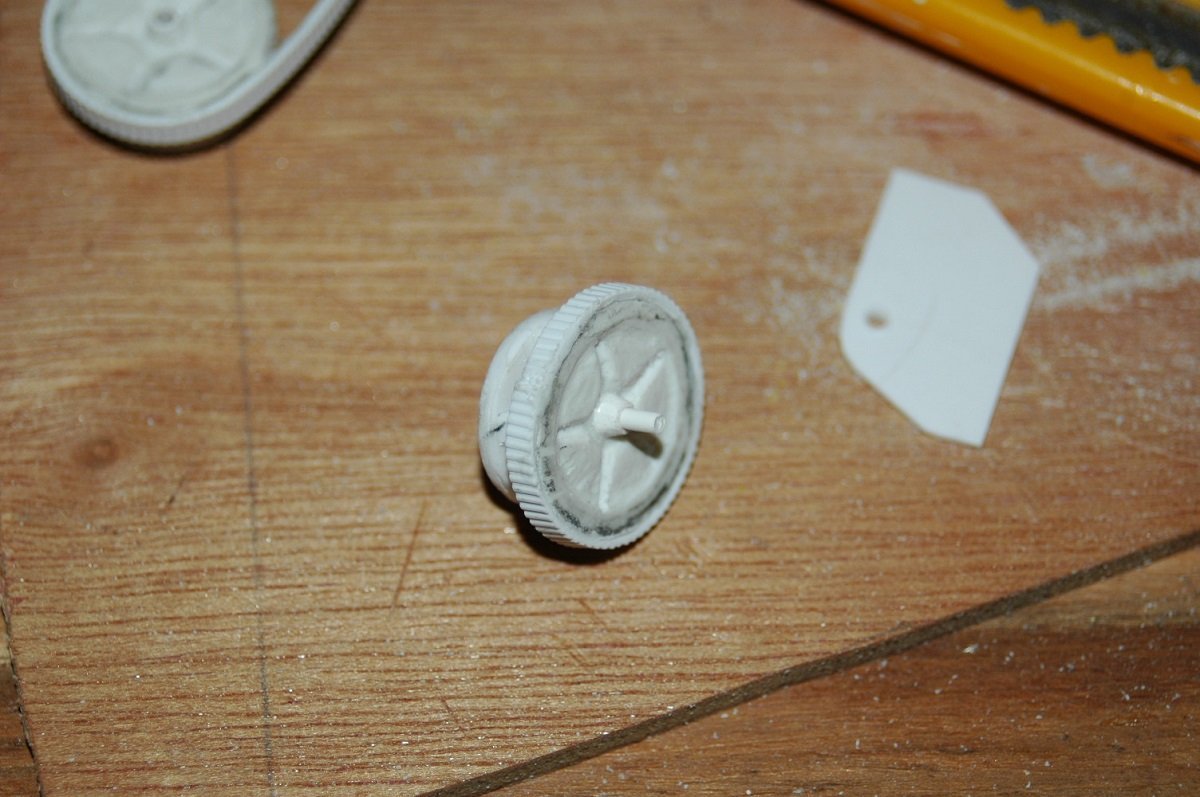
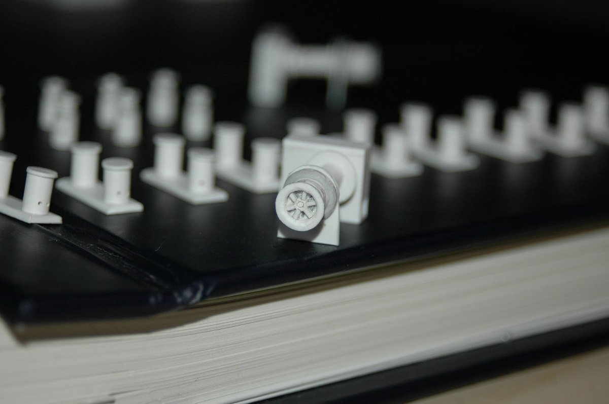
Time for a larger update. Finalizing the hull. Since I had only built 1/700 scratch builds at that time, I had no way of adding names or lettering to a model. This model required it of course. So after some thought I decided to cut masking tape and paint the name etc. For the draft marks I bought some vinyl draft marks from BECC in the UK. I then built the anchors. For the aft marks, I had to improvise, considering the curve of the hull. So I cut up the vinyl ones, divided them to where they were acceptable, and then filled up the missing ones on the strongly curved part by painting. Second part of this update is the mooring station forward. As I was busy with the anchors, I decided to finish that part first. Part of the windlass. If I remember correctly, I first cut the circles, then carved the inside, and then laid a strip of Evergreen (clapboard or something with a similar groove) around it. In the upper left corner you can see the other wheel in progress. Lining up the whole thing. You can also see the evolution of the entrance to the forepeak/Bsn store in following pics. The little frames are made of litho again, as it's sturdy and narrow, perfect for this kind of detailing. Not sure where I got the anchor chain, but I do remember it's slightly over scale for this ship.

-
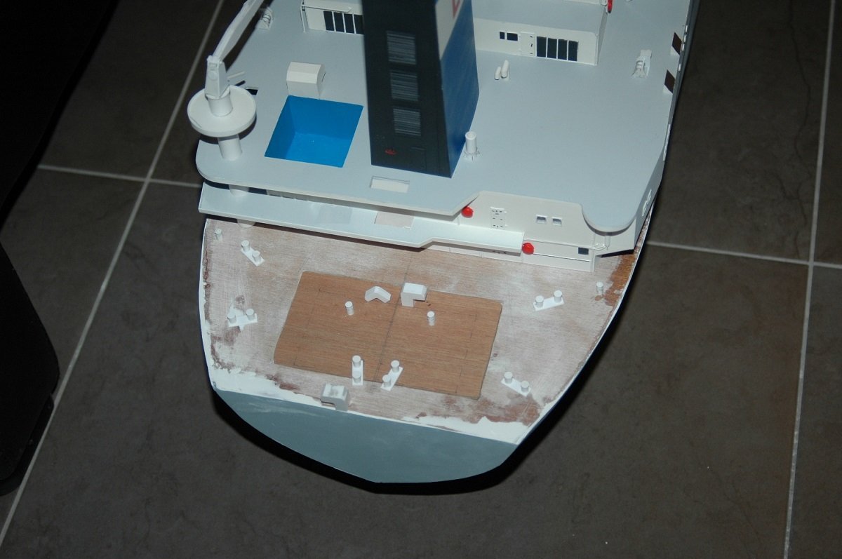
Thanks Thuky and Glen, Since this hurdle was passed, it's time to finish this thing. First was something I dreaded for a long time... Putting windows on that accomodation. Decided to make a tiny mask from a piece of masking tape, with just the upper and lower boundaries of the windows, so I could at least have them straight. I then used a fine tip marker to put the windows between those boundaries. Since I was free in positioning the windows, I could use the same mask for 3 sides. Only on the aft I couldn't use it since I had already placed the outside decks there. Apart from the accommodation, I only have to put lifeboats, crane, the cutter platform forward, and the masts and exhaust pipes on the Spartacus. Most of the work is remaining on the multicat. I gave the superstructure a coat of white and started building its two heavy cranes. They are telescopic cranes without a wire. The hook is directly connected to the extendable jib. Since she is underway in the diorama, the cranes all fully retracted and folded in sea fast position on deck. A typical case of keeping a handle, I drilled a 0.5mm hole in a 1mm thick piece of styrene, then cut further to shape. I then glued the "jib" in that hole and the last action is to rease the tiny crane body from the piece of styrene. I then glue it to a 1.5mm dia x 0.3mm thick base plate. The foundation of the cranes was already glued inside the hull before, I used those to keep a hold of the hull during pouring. Here you can see the rigging that got loose between the gantry and the ladder and the anchor boom and the anchor hoisting wire. I believe overall the epoxy shrank and pulled the vessel down a bit. The wires inside the epoxy are straight/tight, but once above the "water" it all got loose. Also the edges of the epoxy block are somewhat raised, which, I believe, means the center shrank during curing. Not much, but at this scale...
-
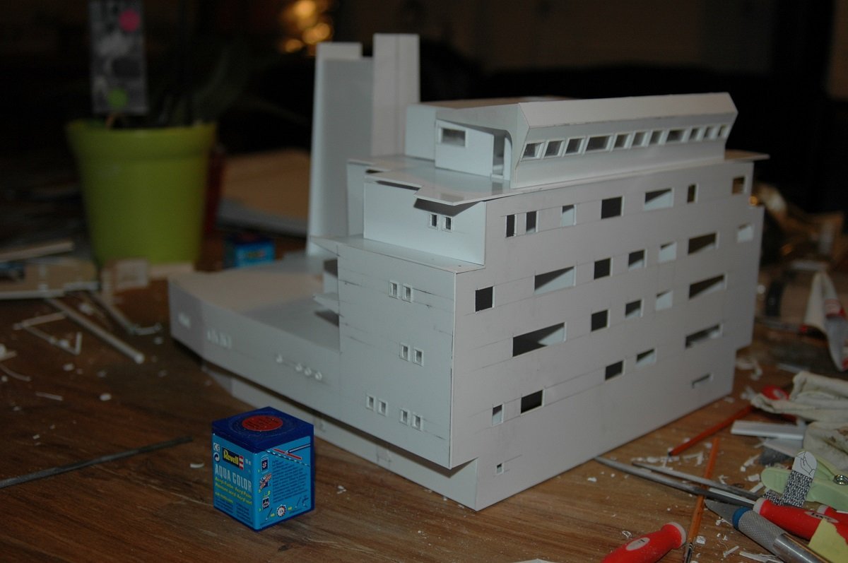
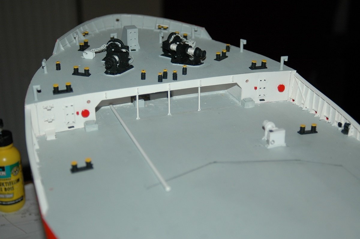
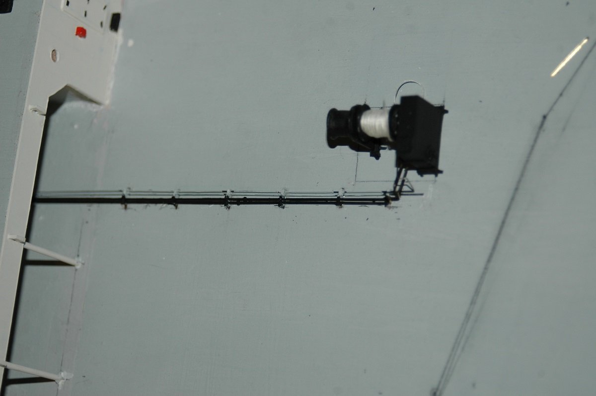
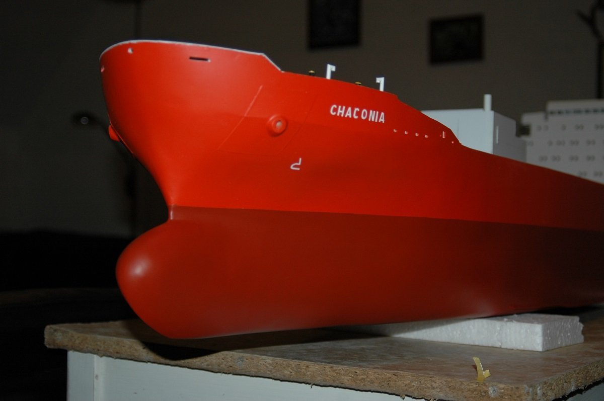
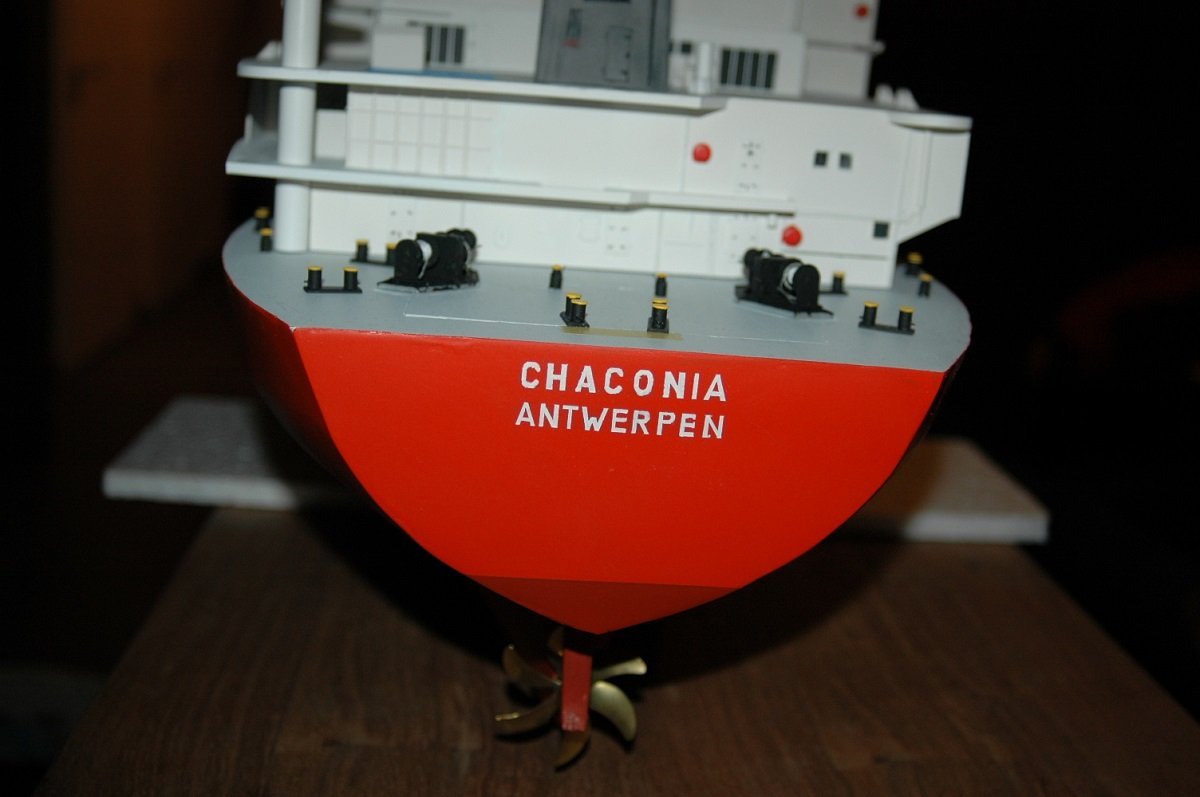
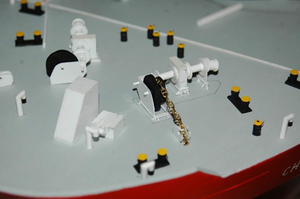
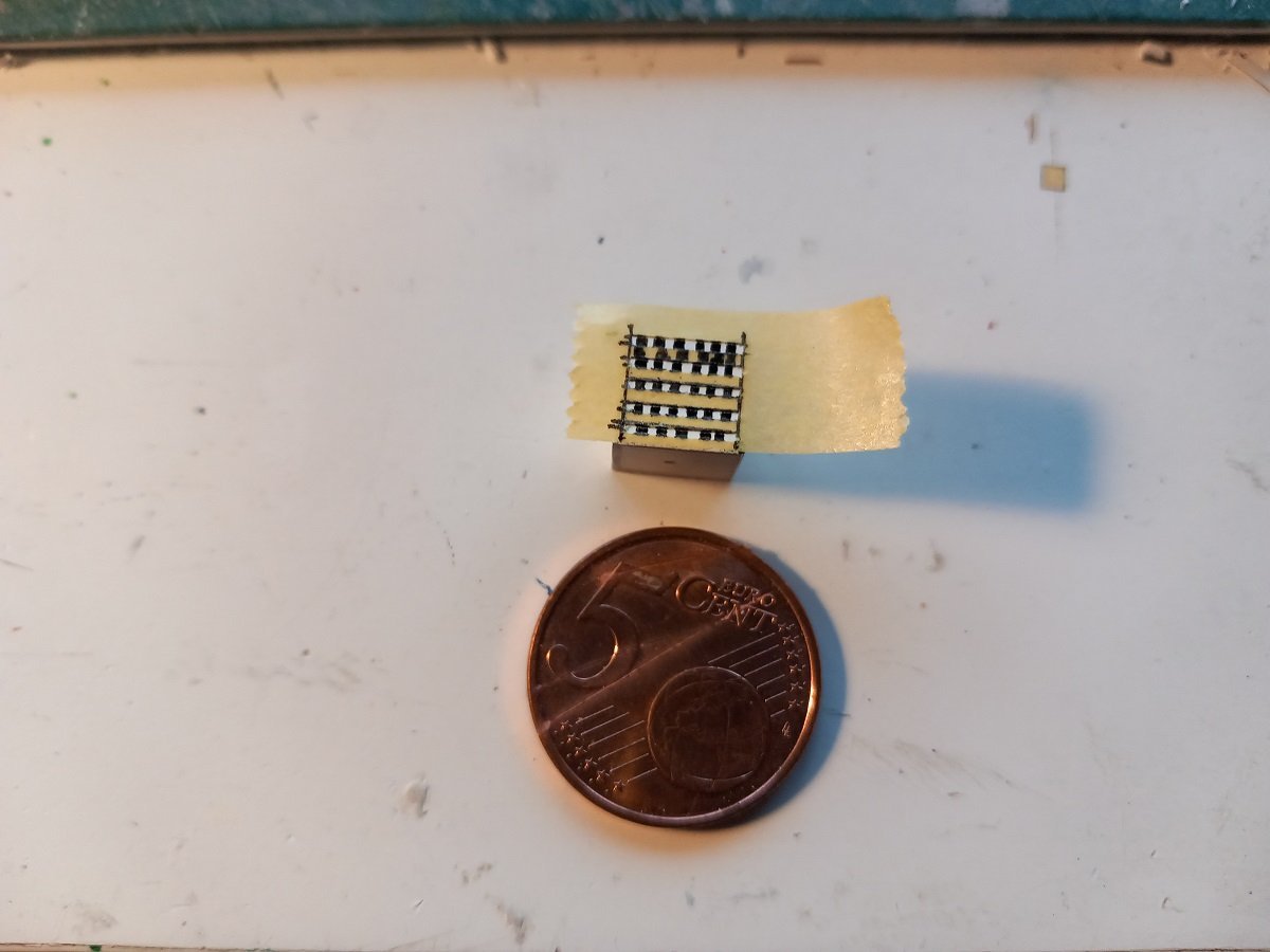
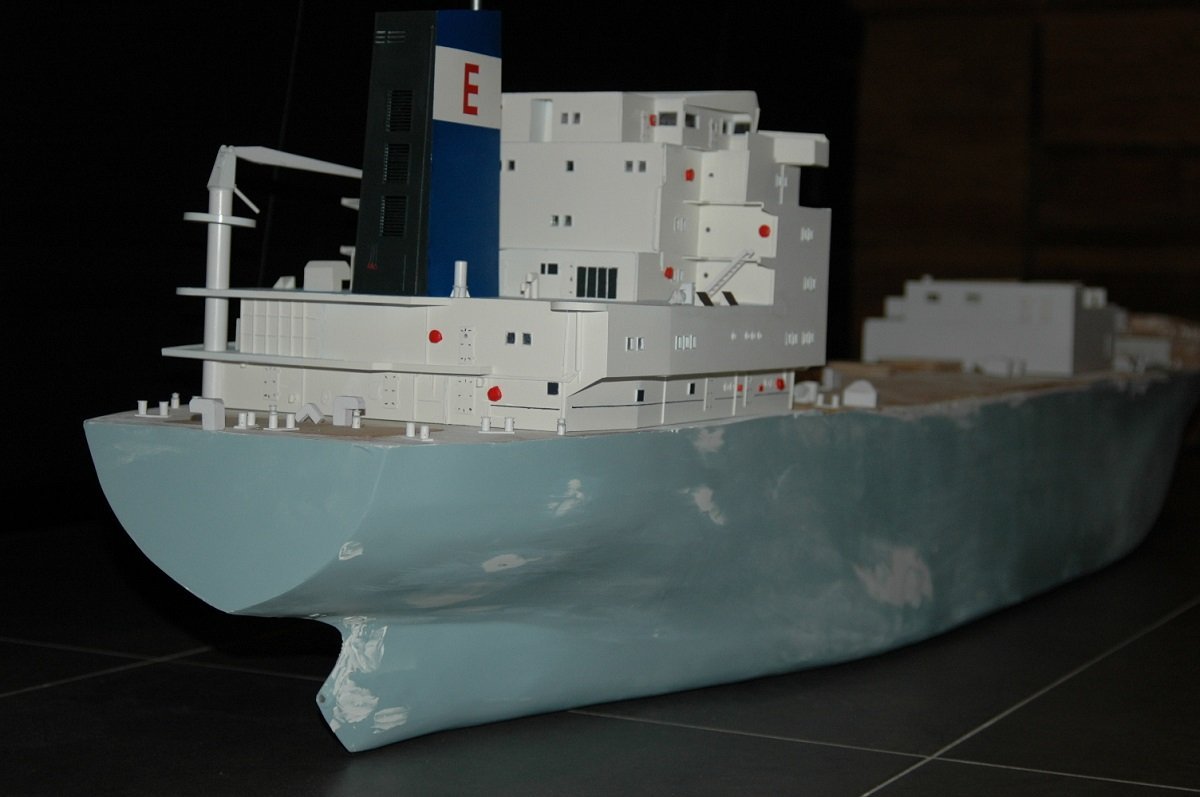
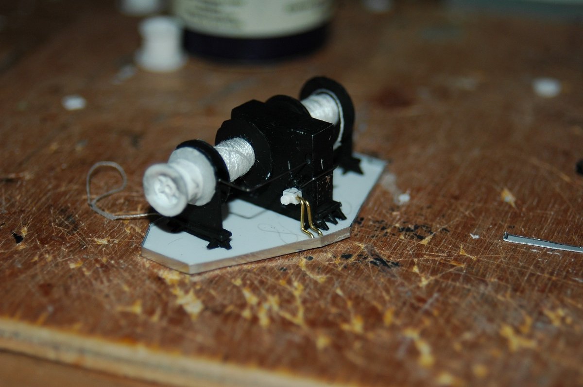
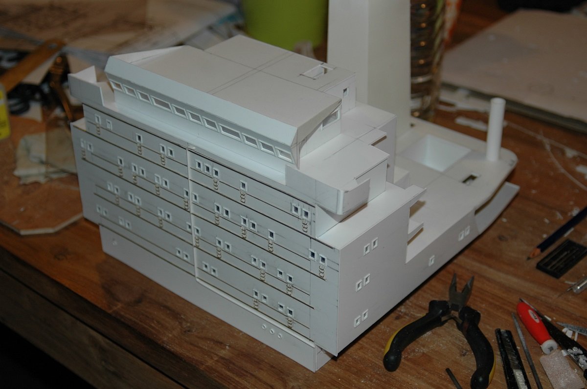
Hi Andy, that won't be necessary, I'm currently employed on a vessel built in 2019 and before that I was on a vessel built in 2016/2017 (and before that on a series of vessels built 2006-2012). The last two I followed up during construction in the yard and took them out of the yard later on. That's exactly where my doubts have originated. I believe Chaconia also had the stairwell construction of A60 already. The whole series of LPG tankers were built in the beginning of the 80's, with '70's technology, however they'd have to comply by the rules of those days and I do believe that fire integrity was already a requirement back then. Today's update is some of the detailing on the vessel. Each cargo tank was equipped with a "gas dome" or "vapour dome" and a "pump dome" containing all gas connections as well as the filling line of the tank and manholes for tank entry. The pump dome being aft, containing the 2 cargo pumps, the level gauge and the bulkhead valve. The tanks are split in 2 longitudinally, for stability reasons, but there is a valve in the separating bulkhead to equalize the level in both sides of the tank. The top of the tanks, where normally the vapour phase of the gas would be, is also connected. I made the main structure of those domes from wood, but clad it with Litho plate, a very thin aluminum plate used in the printing industry. I also found a picture of the rudder under construction. The rudder is basically a brass plate on a brass rod, I then put a top plate for the shape and filled it with epoxy car body filler. Before all that, I added a ring, where the rudder support would come. The ring can turn independent from the rudder stock, and will be built into the support. (if that makes any sense) And here you see some mooring equipment. In the upper left corner you see 4 dry powder boxes, which are mounted on deck and contain fixed dry powder tanks for fire fighting. In the far left upper corner you see the start of the ventilation fans. Each tank had 2 large ventilation fans (with heating) installed near the vapor dome. These were used to heat up the tanks and gas free them for entry. And a detail shot of the mooring winch. The ones in previous picture were mounted on a plate with the drip tray around it, since they were for the aft section, the bottom plate is used to hide part of the rudder access hatch. The other winches are mounted directly on deck, without bottom plate, also with a drip tray around them.
-
Yes, the sides of the block are rounded, that's why it's there. Ropes like this would very rapidly get cut over a sharp straight angle/edge due to the movement of the vessel. The rounded sides of the block eliminate the sharp top edges of the mast cap. In any case, a brilliant build so far! Very impressive work.
- 587 replies
-
- 3
-
-
-
- Indefatigable
- Vanguard Models
- (and 1 more)
-
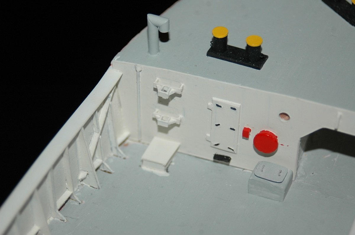
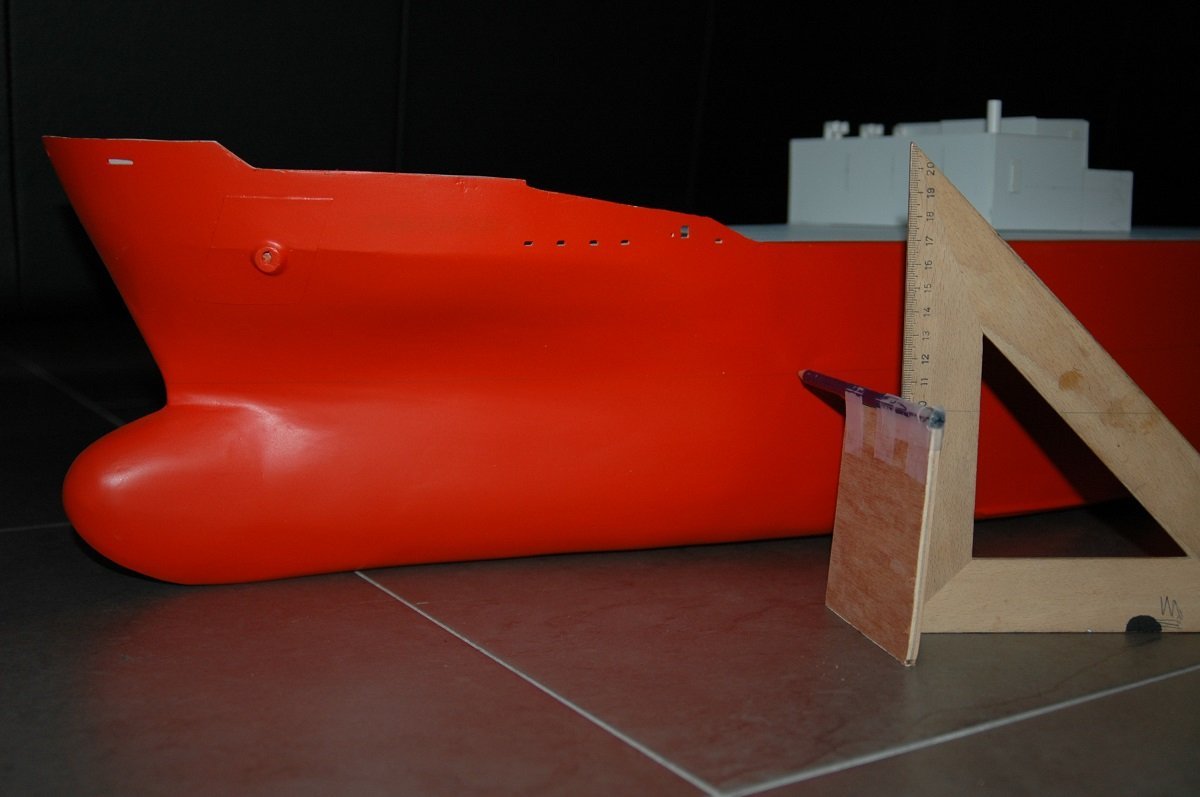
Thanks John. That's exactly what I mean, I don't see that improvement in interior lay-out corresponding with your stated requirements. If I look at ships built after the year 2000, in most cases I have no idea what your alternative route would be in case there was a fire in your alleyway. If you are in a forward cabin nowadays, I don't see you reaching any escape door or staircase (in most cases there is only 1 staircase after all). I assume that to comply with regulations, they see the second transverse corridor (which was lacking in the older vessels) is considered an alternative, but in reality that second corridor, since it doesn't have any doors, will fill up with smoke equally fast as the other one. So if I'd have the option to go through the front window instead of going in a corridor filled with smoke, without really having an idea where the fire is located, I'd opt for that front window. It's dangerous yes, but passing through a smoke filled corridor, potentially ending up near a fire source, is more dangerous still... Some more accommodation finishing. You will also see later on, that the sides of the accommodation are used to protect the lifeboats from any deck fire. Something that isn't being done nowadays neither. Probably it's the larger beam of ships that prevents it, but it was quite a good idea at the time. It also appears the same accommodation blocks (and modifications of it) were used on other types of vessels built by this yard (Boelwerf at Temse). The small hatch in below picture is an access to the rudder itself. The servo powering the rudder is mounted below the accommodation block, but the rudder itself and its connected linkages are below this hatch. It was blended in later on with filler for a better fit with the surrounding. I assume I was waiting for the weather at that time before continuing on the hull. After the initial coat of bright red, I marked the waterline to continue with darker red as anti-fouling. I also immediately made the markings on deck, as they'd be difficult to do once the detailing had started. I then started detailing with the mooring equipment. First I did the forward and aft mooring areas. And the I started with the central, cargo part. Generally I started from the bottom upwards and from the center outwards to avoid interference while mounting and detailing things. Here is one of the mooring winches. This is where I put myself into trouble. Starting with this level of detailing, you force yourself to maintain this level on the whole ship, and eventually that's what bogged me down and stopped the build (not before continuing for a few years though).
-
Very nice work indeed Nils. Love that rivet detail on the plating, gives that little bit extra that differentiates it from a "factory made" model.
-
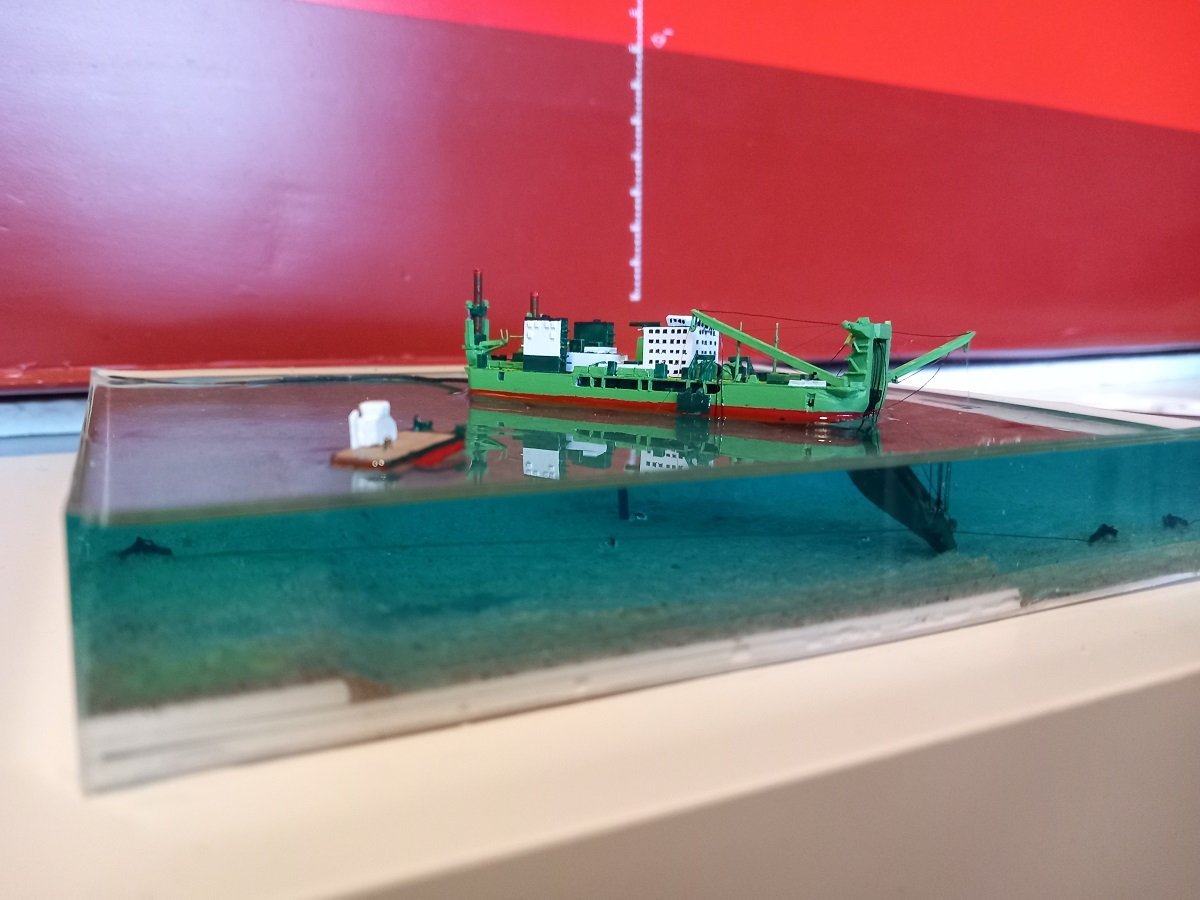
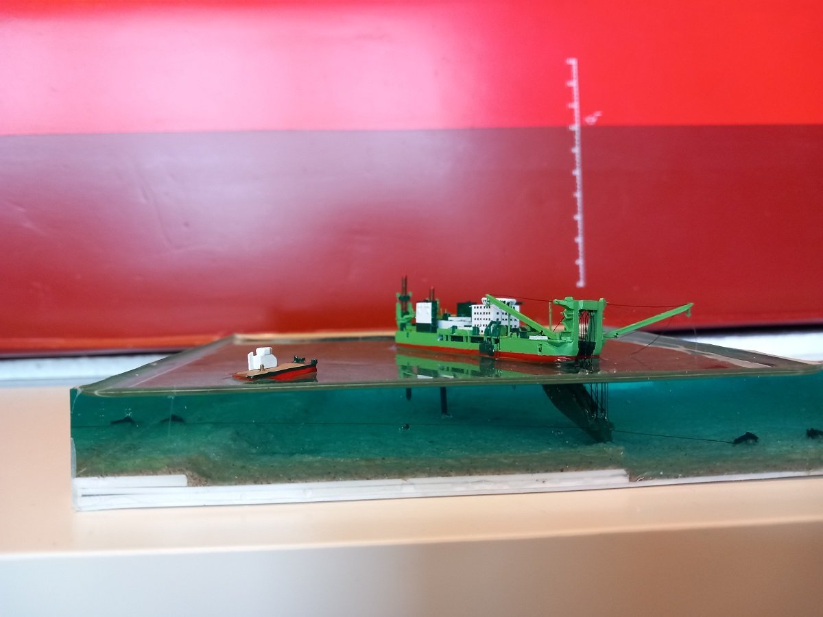
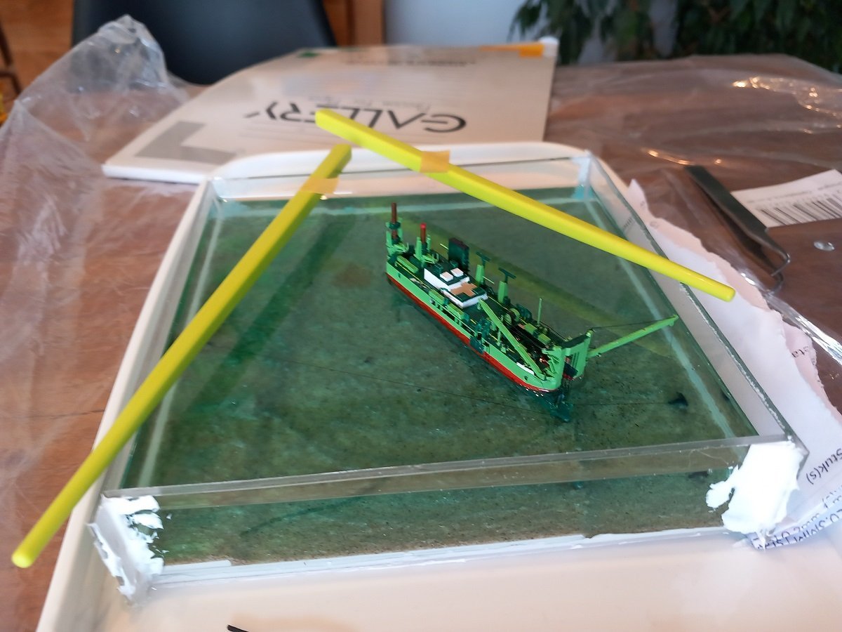
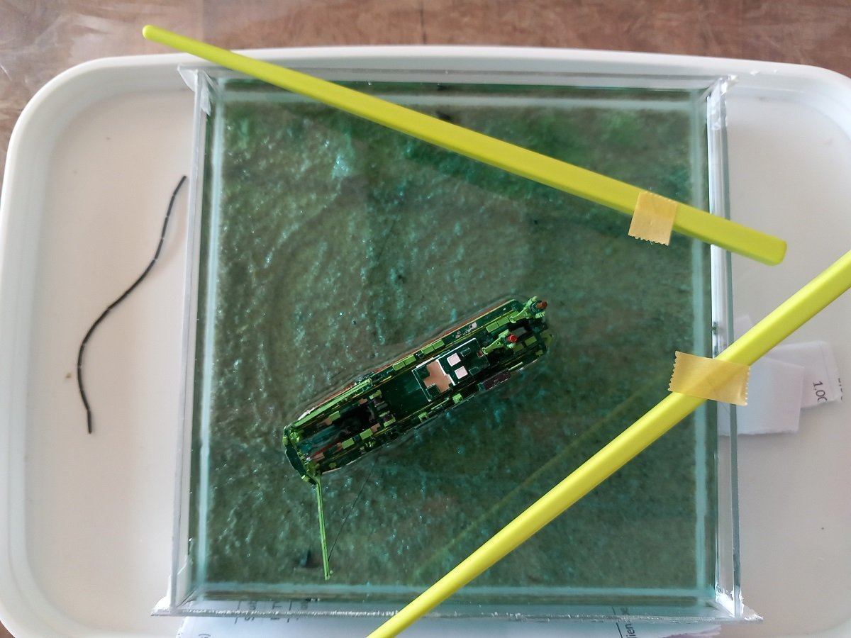
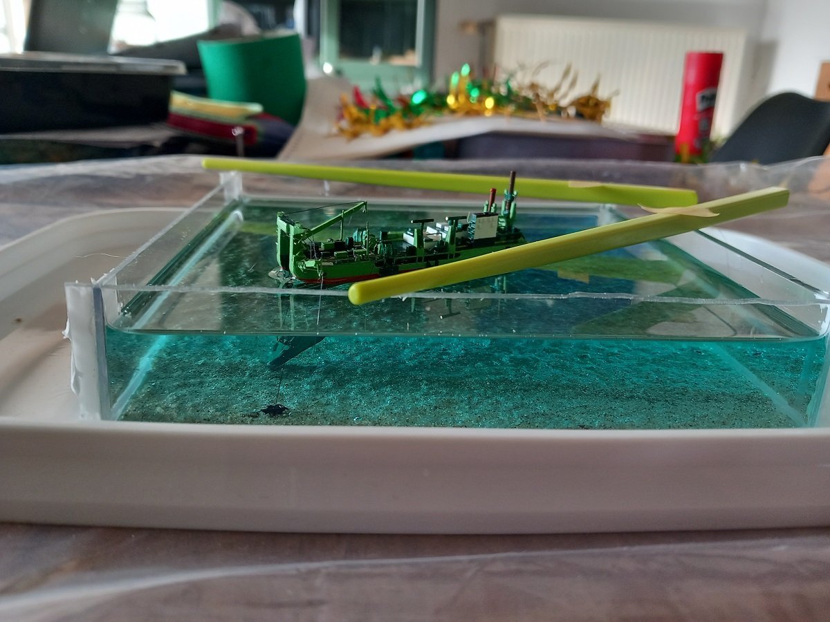
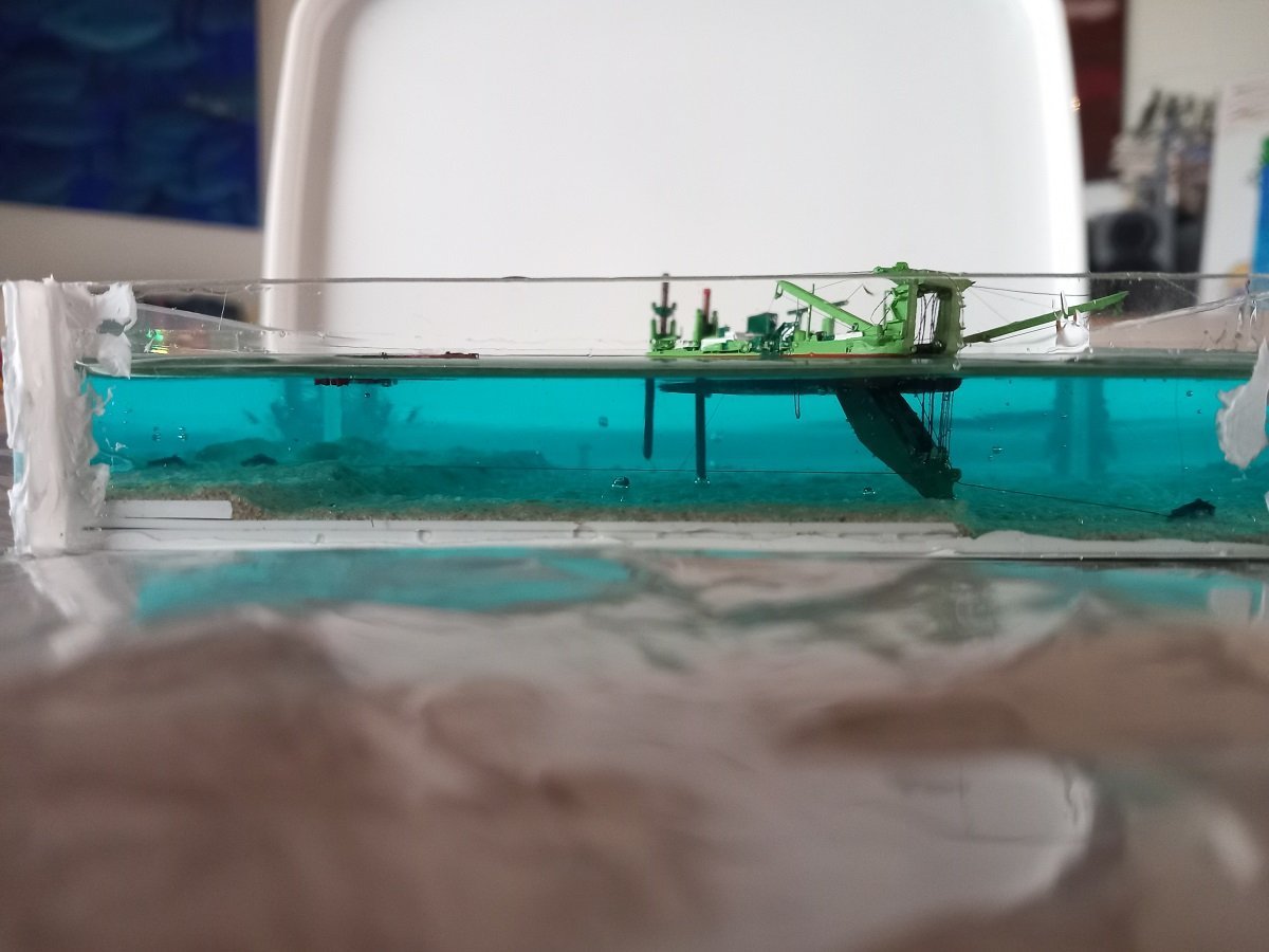
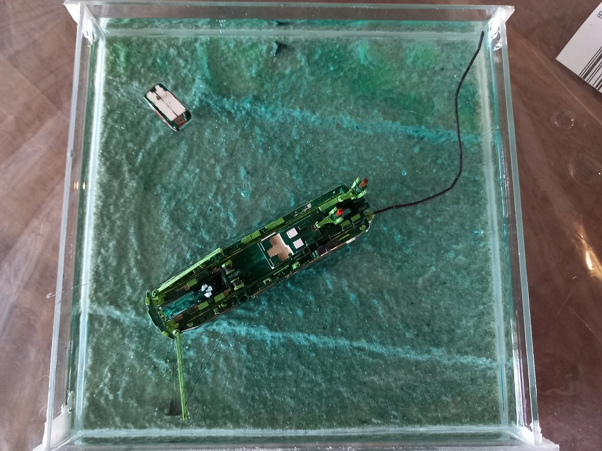
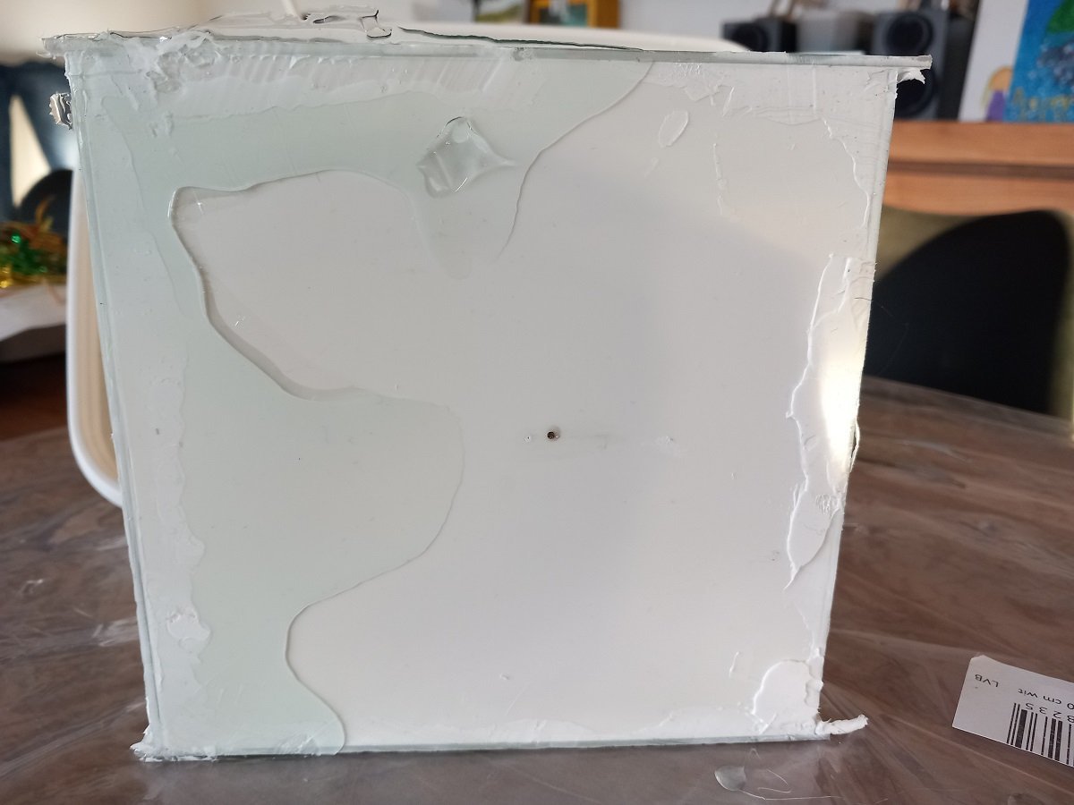
So, although you were all mislead by me finishing that Sea Installer and updating the Chaconia topic, I've actually performed the Epoxy pour on this one as well 😁. So, new epoxy arrived and I didn't waste much time. It started well, smooth, little to no bubbles. However, the foggy looking areas you see in the pictures were actually there. It's not a camera distortion or anything. There seemed to be turbulence and turbidity caused by the chemical reaction. After a while, small bubbles did form again on the bottom, however they came up quickly and I punctured them with a small piece of 0.3mm steel wire. When things got more solid, I helped them to the surface to pop there as well. Unfortunately the whole process took longer than I anticipated, and I had to go out of the house for a while. When I returned some bubbles had formed on the bottom and the piece of wire didn't succeed to get through to them anymore. It is what it is, I do believe those bubbles are formed as part of the reaction and not really coming from cavities in the sand... (in the failed attempt in the glass jar as shown before, there were also a lot of bubbles and no sand on the bottom after all). I also discovered that styrene models don't float on epoxy. I attempted to "mount" the multicat several times, but it sank pretty fast. Funnily enough you really can't escape physics. The after part, with less volume (=buoyancy), always sank faster, creating a trim on the multicat. However, I then decided to wait much, much longer and wait untill the epoxy was nearly solid before inserting that multicat. The floating line I didn't even try until at the very end, since it's electrical wire, it definately would sink. Here everything is already solid. The green sticks in previous pics were there to hold the anchor cable for the floating line and the wire between the anchor of the floating line and a small neuring buoy. That buoy and wire are used to retrieve and reposition the anchors when the dredger moves. The floating line was positioned so it would touch that anchor cable. And here's the reason I put inside that plastic lid (yes, it's standing on its side for the picture, it's really solid 🤪). The small leak actually occured when I was trying to lift it on the side. The vessel has a serious list, I was trying to compensate that by tilting the waterline. That would have looked odd, so I accepted the list. The anchor boom is out after all, so she would have a list in this action (however, not as severe as it is in the model). The leak stopped when the base plate was put on the lid again, so I didn't really lose much inside my box. The blue colour has somewhat ligthened the sandy bottom and gave a nice contrast with the side wires under water. Although I'd need the acrylic gel to touch up a few places and hide a few faults in the epoxy surface (and perhaps hide the air bubbles a bit), I'm now in doubt whether I would put acrylic on top or if I keep it like it is...
-
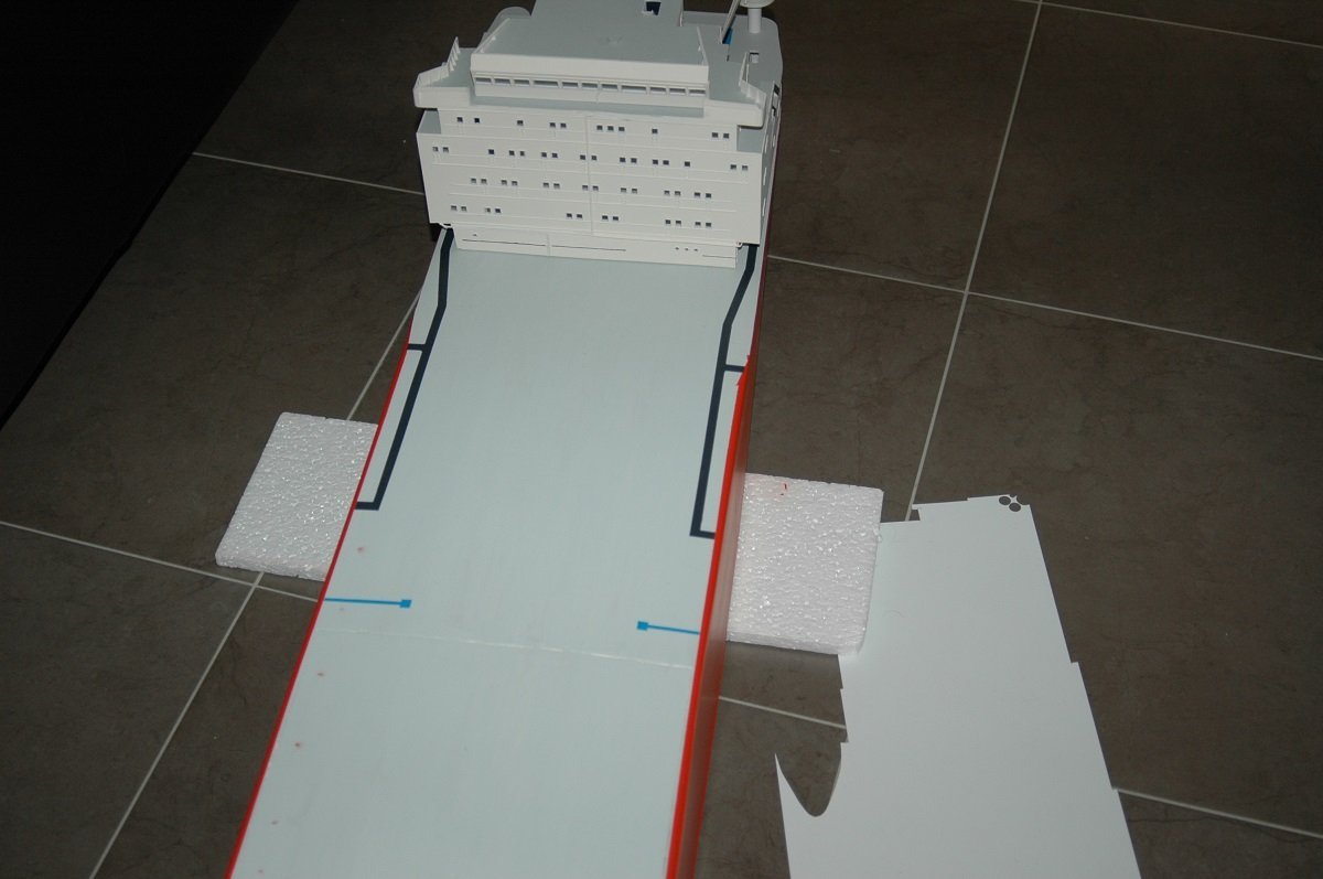
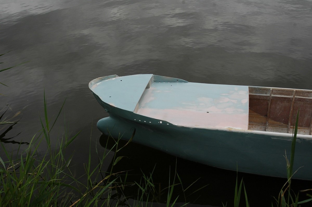
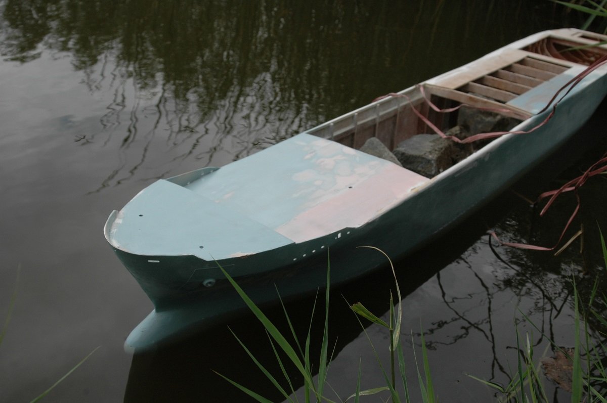
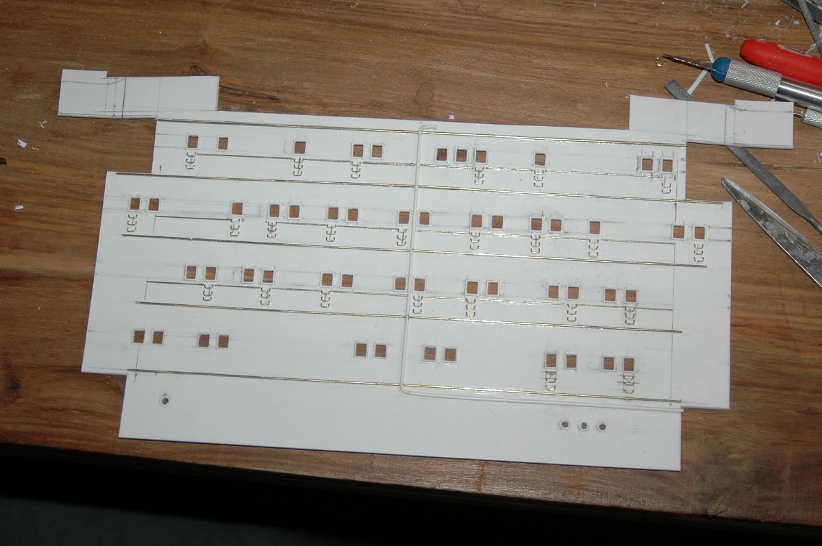
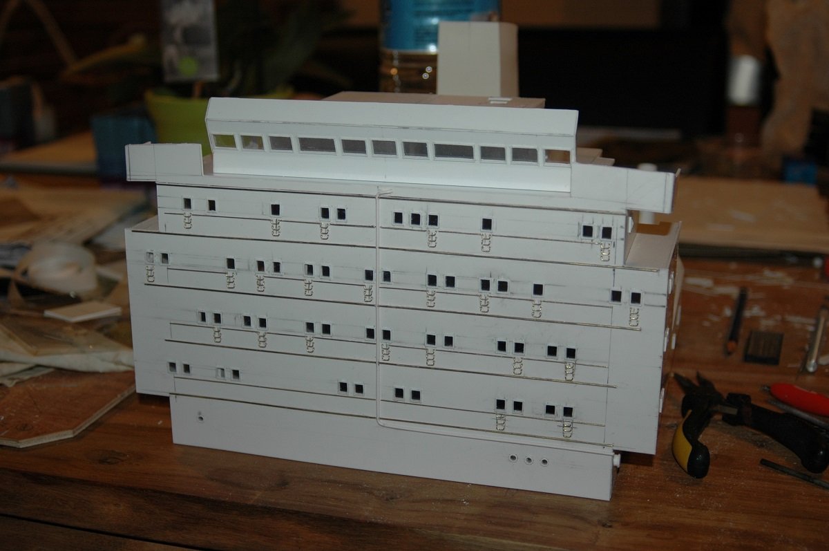
I did read up on this before starting this whole endeavor, so I did put the cloth first. I didn't use a squeegee, not sure what I used, but when I started pushing the resin through the cloth, the edges of the cloth started raising (which is what you see in the pics), since it couldn't follow the curves of the vessel. A few extra cuts on the cloth or simply more time to push it down again would have fixed it. Instead, in this situation when I was trying to fix it, the polyester hardened (I'm talking about 5-10 minutes of working time) and since it's a big hull I was still spreading resin on the rest of the vessel when it already started hardening at the other side. That's exactly why I'd use the slower curing Epoxy next time. From here on my records are more fuzzy. I'll just show the pictures and try to keep it in a somewhat chronological order. When the hull was complete, I did a water tightness test with some stones to see if the weights needed were corresponding to the scale weight calculations. And I continued with the accommodation block. I usually wait with that for a hull to finish (also in small scale builds), because the bridge wings have to be matched with the width of the vessel. As mentioned before, I did the facing separately. You can see why... Drilling so many holes in a thick plate is not easy. They built those ships in the 80's, I guess they took in account escape routes much more than they do nowadays. The cabin windows were the escape route. There was a hammer on the inside to break the glass and then you could step out, use the small steps on the outside with the water spray system as a foothold and shuffle to the sides, where you could go down to main deck using a ladder (not on the model for now). Once that facing was finished, I mounted it in place. The large holes on the thicker plate in previous post were made to make sure the windows of the final facing would be clear.
-
Brilliant work. She's already a very impressive model, even unfinished! Enjoy the break.
- 233 replies
-
- 2
-
-
- Indefatigable
- Vanguard Models
- (and 1 more)
-
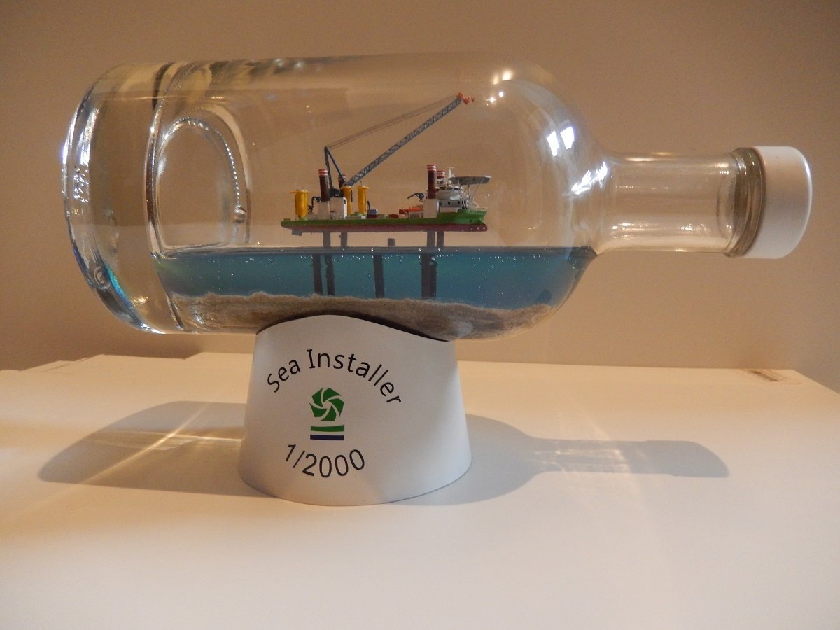
Finally gotten around to finishing this one. The cap was a bit damaged, so I gave it, along with the base, a couple of coats of spray putty, followed by a satin white coat, resembling the colour of these windmill bases. Since the cap looked somewhat like a hub, I played around with the idea of putting the 3 openings or at least base plates for the windmill blades on it, however I didn't do that. It would probably still take some attention from the ship. I decided to cut some vinyl lettering and logo for the base, since the ship itself lacks the name (of course!). It's a slimmed down version of the original idea, but I think it gives more attention to the ship itself. So I consider this build finished!
- 51 replies
-
- 12
-
-

-
- Sea Installer
- Bottle
- (and 1 more)
-
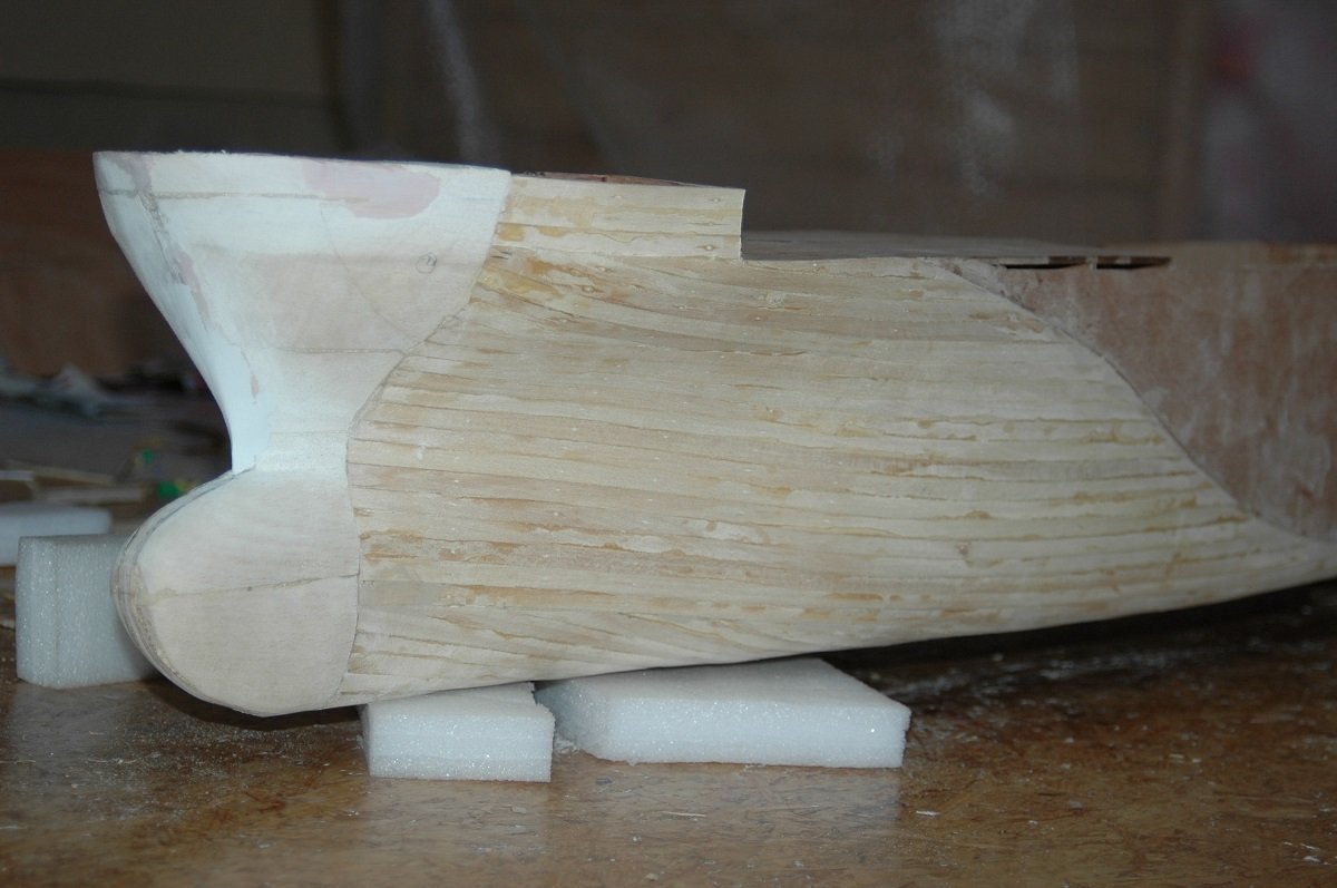
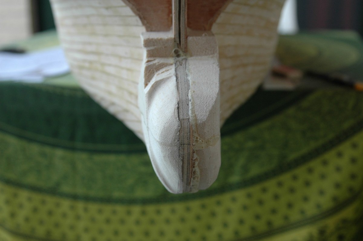
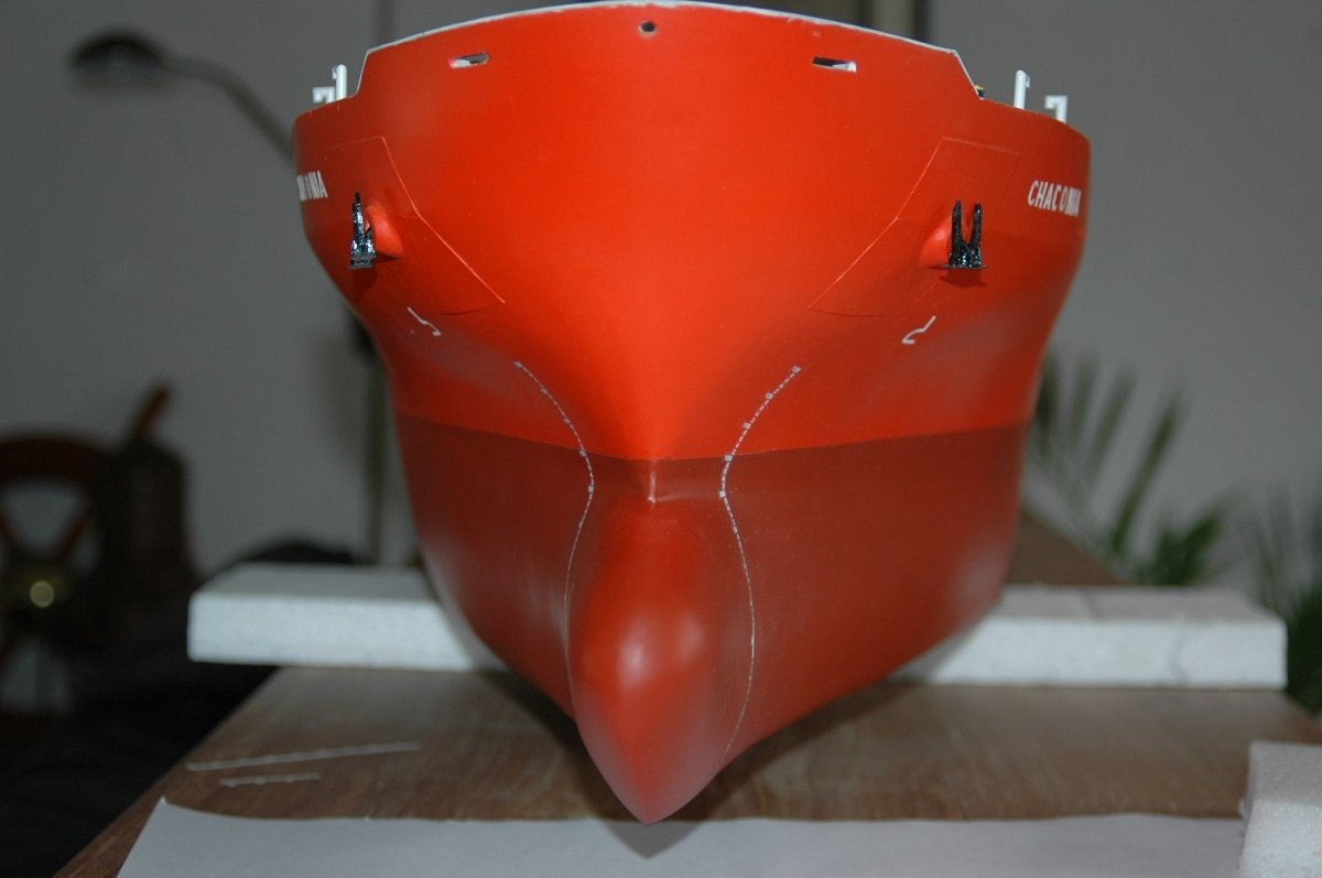
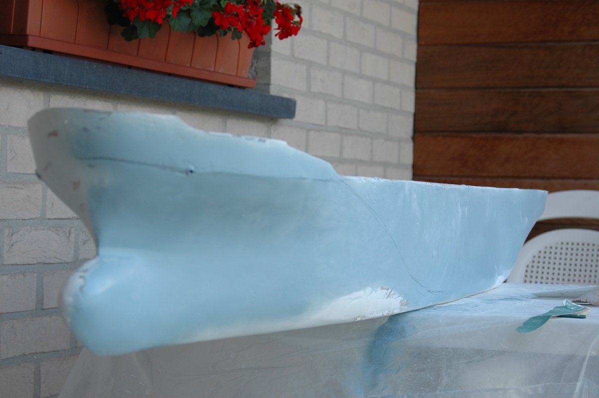
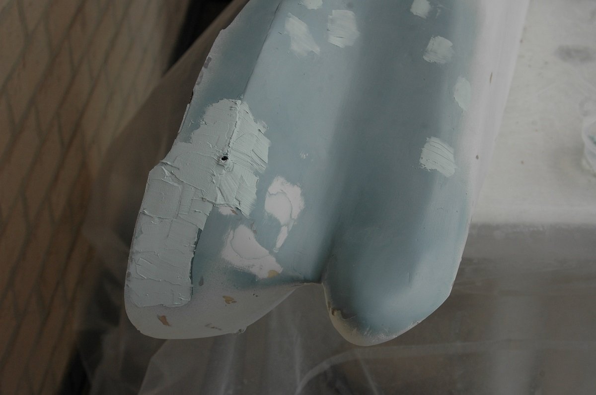
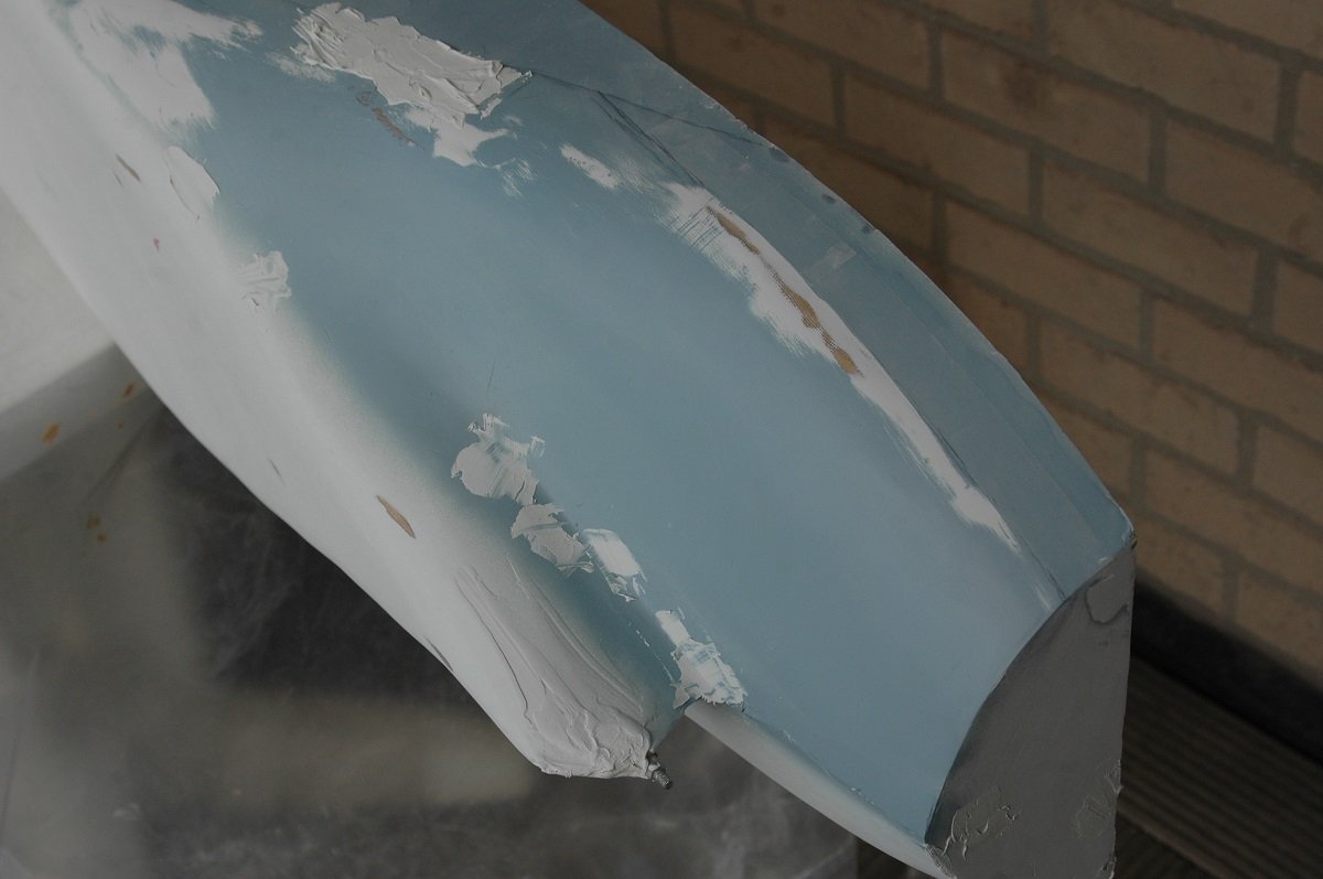
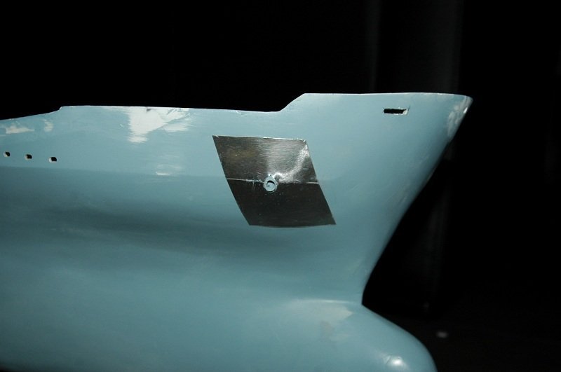
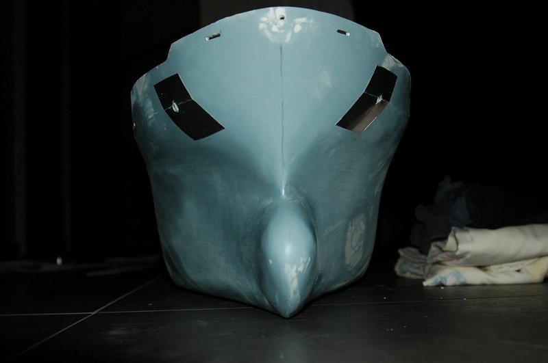
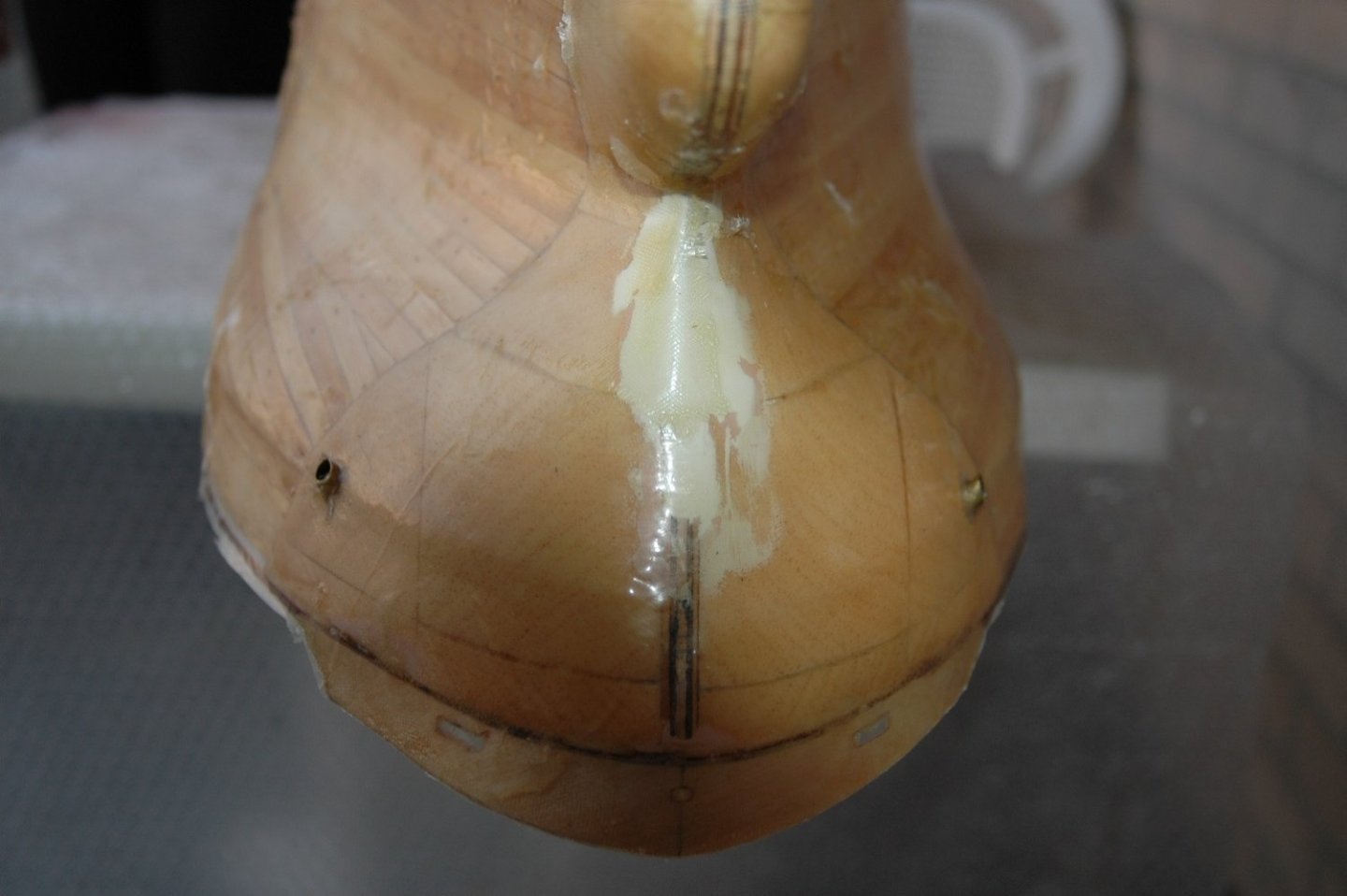
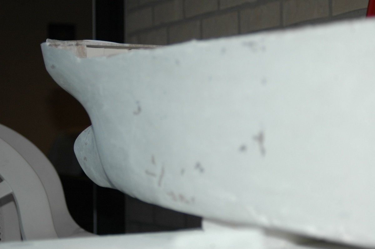
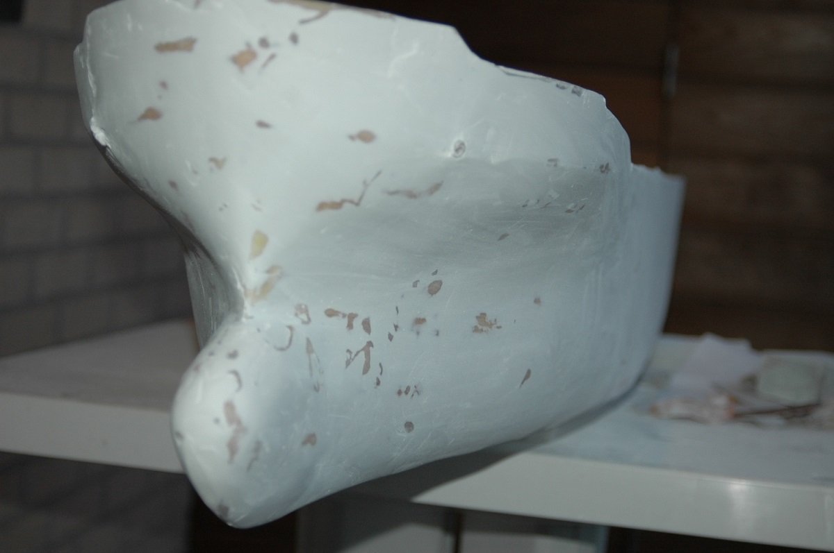
That was indeed the case Ian. All the above pics represent somewhere around 1 year of work, although I must admit it was very disturbed since I sailed 3-4 month contracts at that time. Since I was only home a couple of months a year, it was also very much weather dependent (had to be home in the right months of the year) and of course a lot of hesitation was involved since it was my first one in this scale and style. Epoxy was coming up as a modelling material at that time, but there was a lot of talk about toxicity etc. and I believe it was also a lot more expensive than polyester in those days. In any case, I'd use epoxy if I'd do this again. The slower curing is quite a requirement for this kind of job. So next is the continuation of that hull. After the first layer, I sanded it all down again and once I was more or less happy, I put a first coat of sacrificial primer. I used gray as it would show the bumps and pits better. After that I filled the pits with more putty and sanded it down again. My mistakes at that point were that I filled too little. I learned that you had to fill a larger area around the pits in order to sand it smooth with the surrounding. In any case, this was followed by another coat of primer and a series of small patches to arrive at an acceptable result. I seem to have lost some pics from that phase as well. After the body work, I placed small litho (aluminum) plates around the anchor hawse pipes, since in reality the steel plating is thicker there to protect the hull from the anchor flukes. I afterwards added the two "warts" on top of those plates, that give the anchor a good position when it is inside. And the final shape of the bow.
-
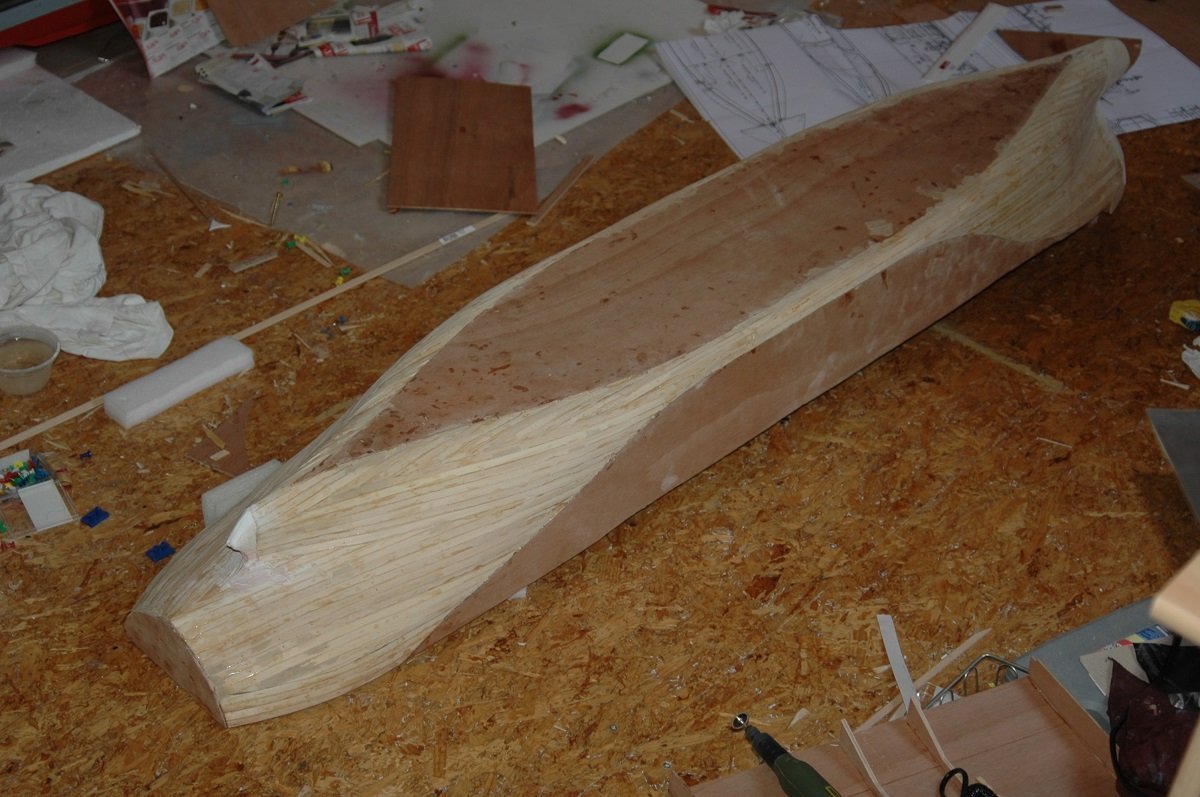
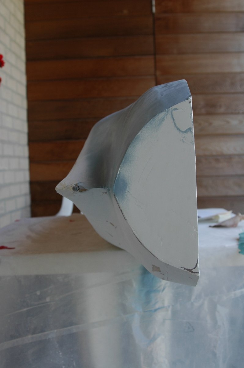
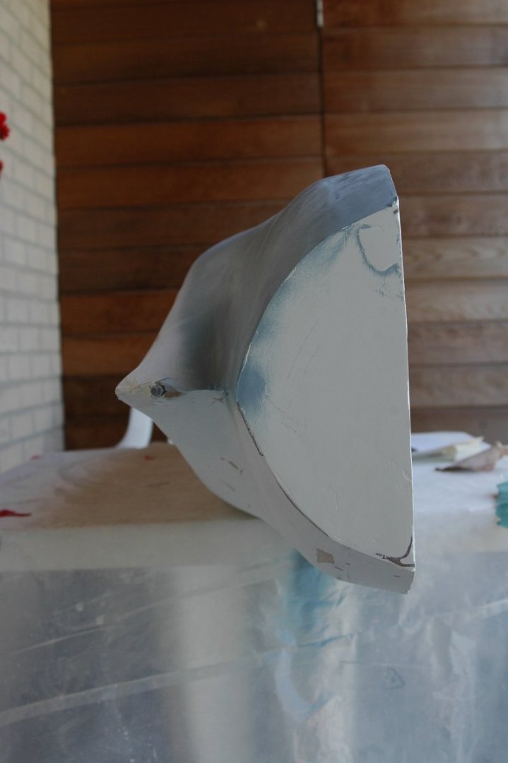
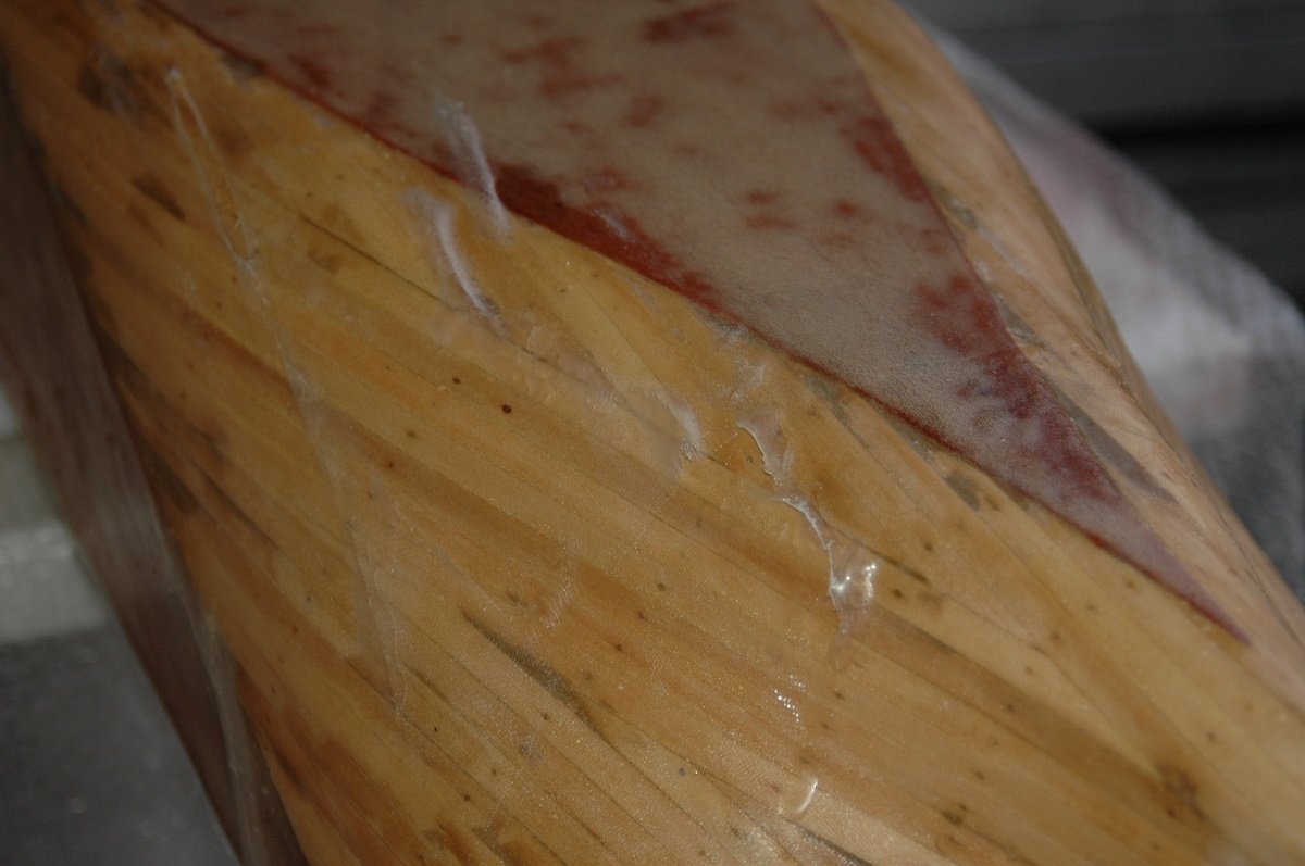
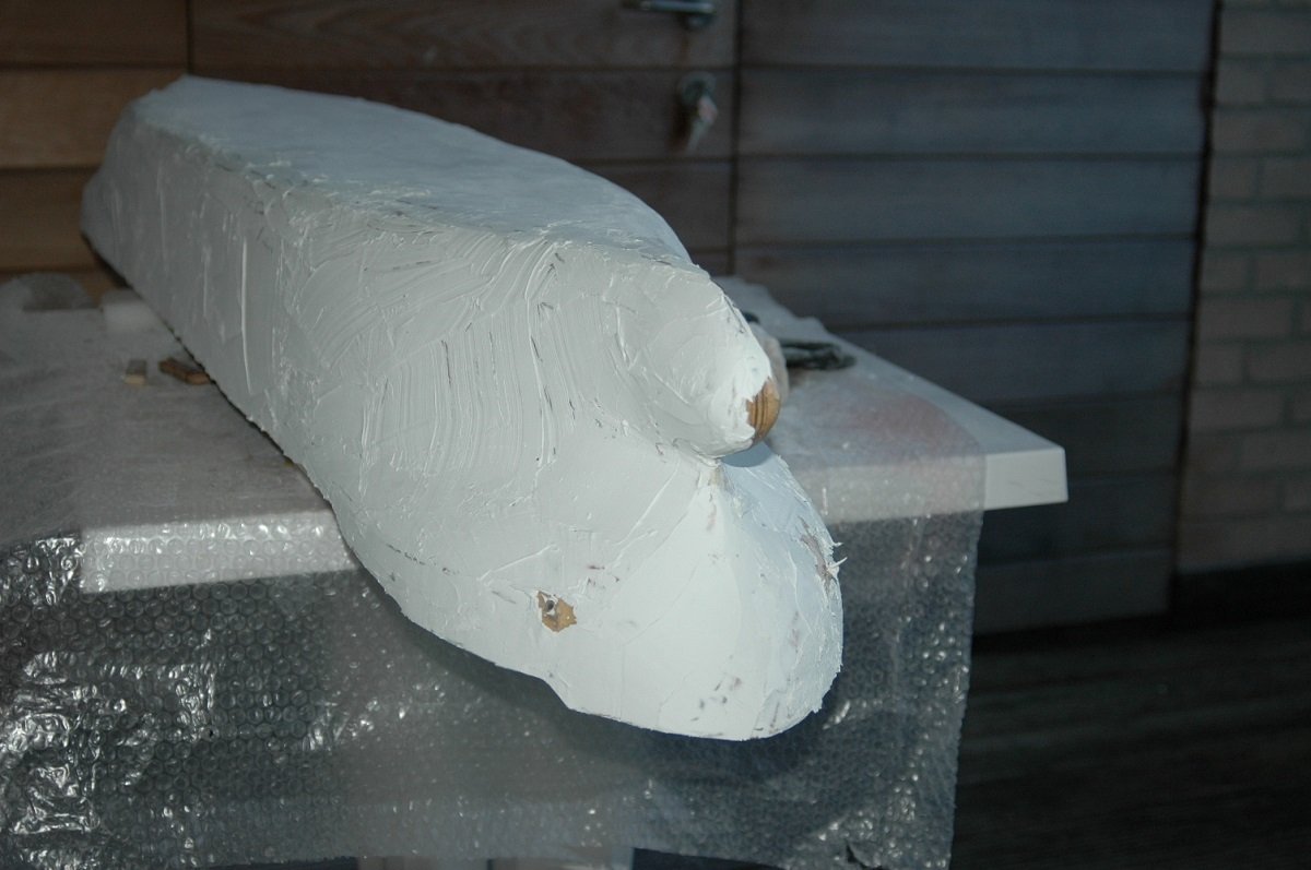
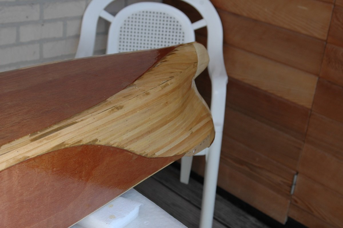
THe pictures aren't really ordered well on my pc, so here are a couple more planking pics of the stern. You can also see an inserted brass pieces to make a sharp transition above the propellor area. And an inside picture, showing the large volume inside the vessel. Back to where I left off last time. After the G4 came the fibreglass job. Again, never did anything close to that before and it turned out a small disaster. First of all, I did this on a rather hot day, reducing the curing time of the polyester resin even further. Secondly, it appears the G4 was still curing/drying, although I was already quite long past its normal drying time. I believe this had to do with the diluted G4 inside the wood. The result of the first mistake was that the polyester cured extremely fast, resulting in piece of fibercloth still sticking out without time to put it down in place. Also the mixture may have been slightly wrong as there is very little room for error with a mixing ratio of 97% A qnd 3% B... Probably too much hardener. The second mistake resulted in bubbles below the polyester shell. All in all due to the fast curing, this didn't really deform the polyester. The bow came out quite nice. As I mentioned, most things can be fixed, but making a good job from the start will save a lot of time later on.... In this case I started sanding away the fibercloth that was sticking out and resorted to a full cover of car body filler (also polyester based), followed by a LOT of sanding. And this angle was chosen to verify if I captured that strange bow shape properly. This already gave me some courage to proceed (something I was slowly losing after the polyester set-back.
-
There was a time when I created part of the gifts themselves, in addition to bought presents, but lack of time prevented that ever since. I'd still put something together when asked to, of course. Nice coffee shop. Revenge is coming along nicely as well, when the red part is planked and not red anymore, it will make quite a difference in appearance!
-
Great job so far. You sure are productive. I do get the feeling you're running away from masting and rigging 😏
- 21 replies
-
- 1
-
-
- Amati
- Victory Models
- (and 1 more)
-
Although I'm following you, I didn't see this one pop up. Happy to see another bottle-project started. Already curious how you'll tackle that bottle-waterfall connection!
- 174 replies
-
- 4
-
-
-
- Waa Kaulua
- bottle
- (and 1 more)
-
That's one very fantastic steel job! And at such a small scale! 👍
-
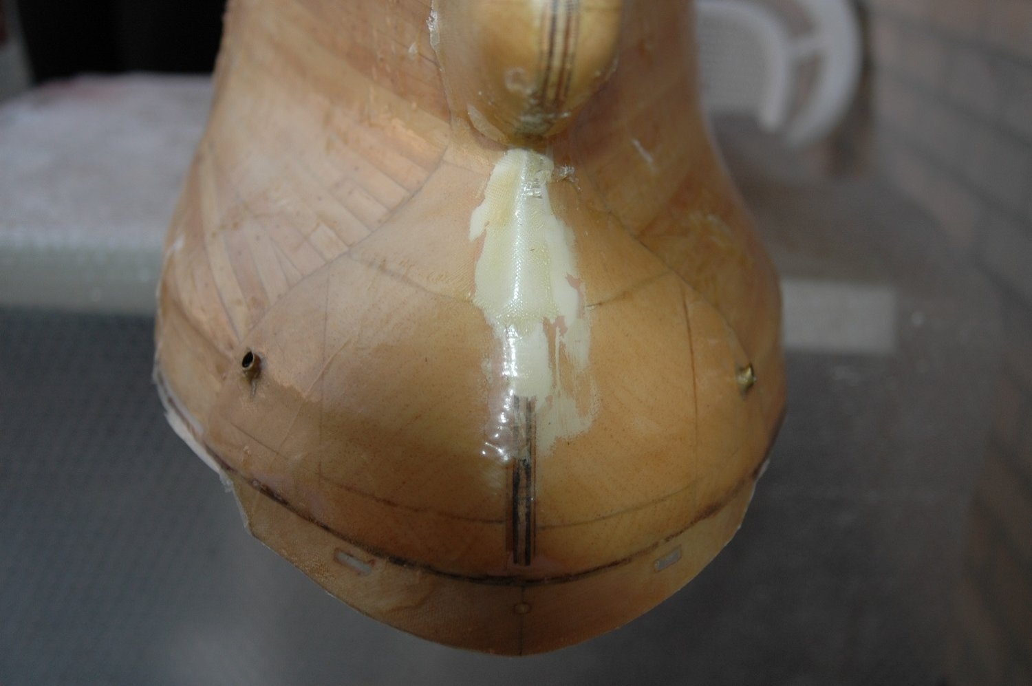
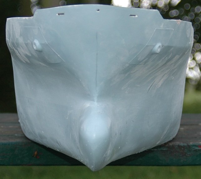
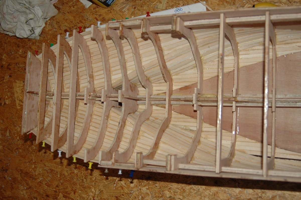
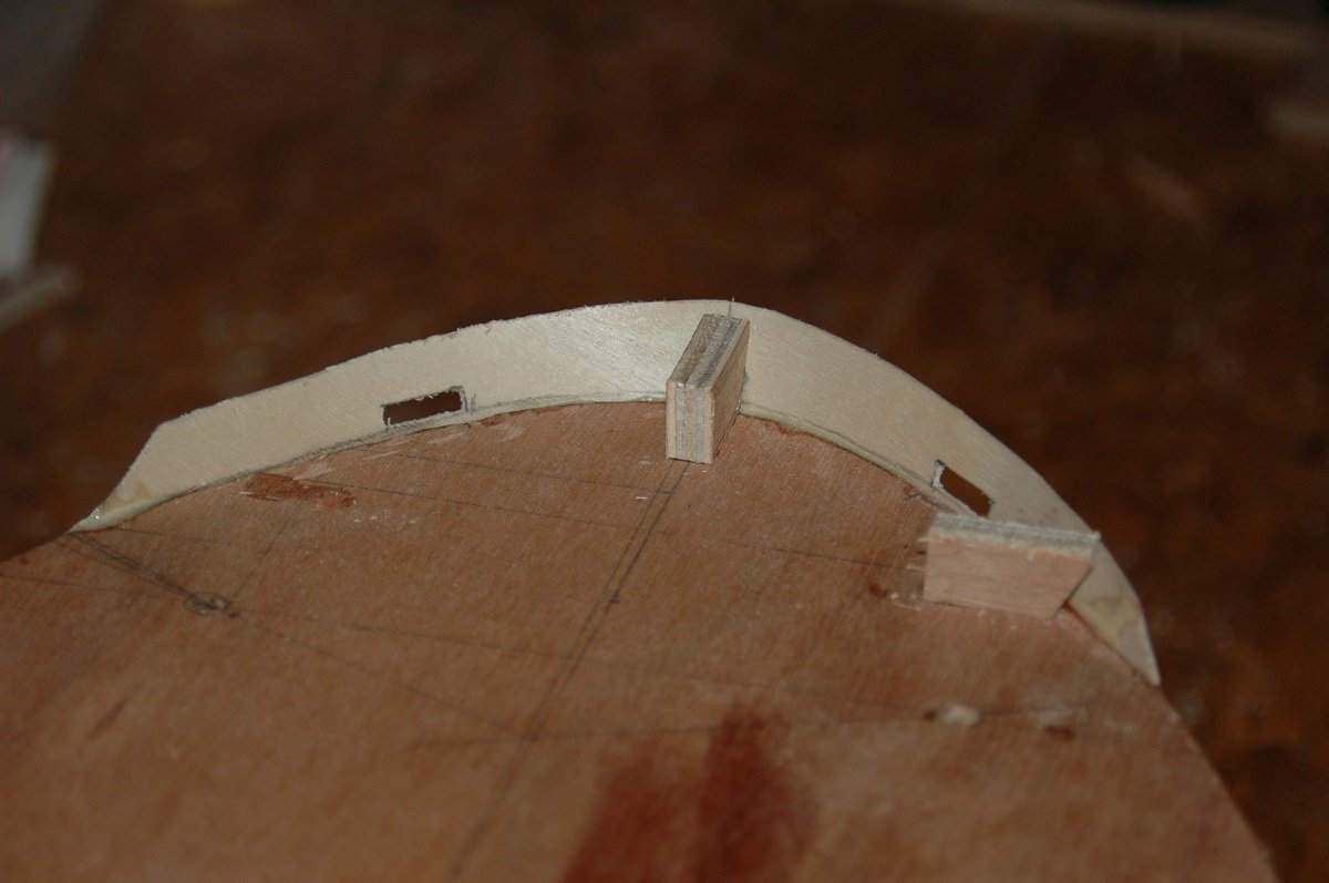
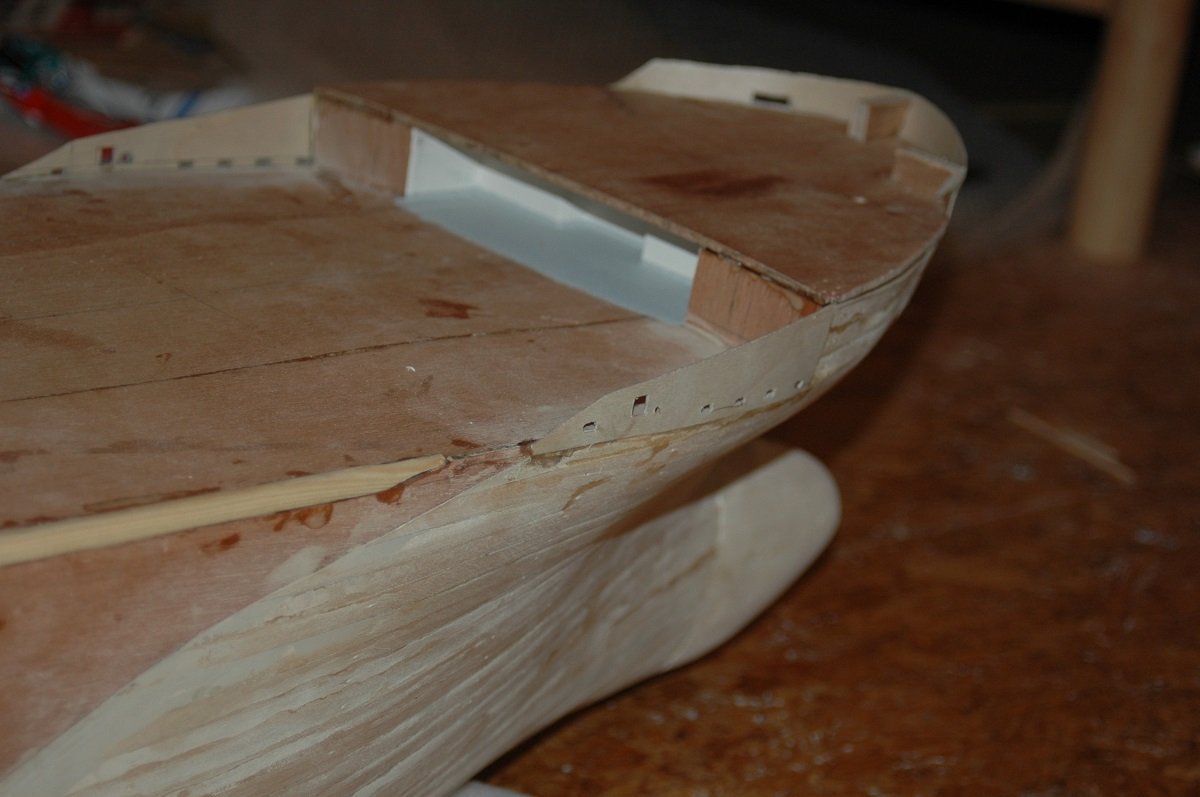
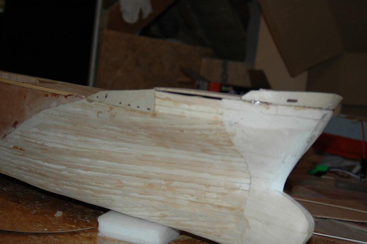
Thanks for all the likes and comments. On to finishing the hull before polyester application. First came the bulwark. Since the deck wouldn't remain pure wood, I decided to glue temporary blocks with the correct angle in place. I then shaped a bulwark from paper around that bow and transferred it to wood. I believe I used 3mm birch ply for this. Also the transitions from the forecastle deck to the main deck were made from that wood. You can also see the finish of the stem, using 2-part epoxy filler around the brass plate to reach a more or less sharp edge just above the bulbous bow. I used a very fine weave of fibre cloth with polyester resin. Since Polyester isn't really 100% water proof, the wood could start rotting underneath. I therefore treated it with a product called G4, which essentially turns the wood into plastic. First coats were thinned G4 to get it deeper into the wood, last coat was pure G4. Here is the G4 treatment. When drying it gave a satin gloss to the wood, but the colour of the wood turned back to "normal", eventually it was hardly visible that it had been treated. You can see small bubbles forming due to the G4 getting into the wood.
-
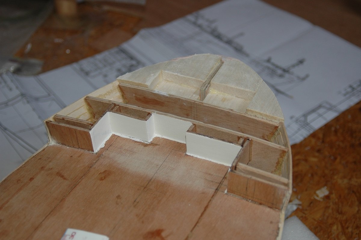
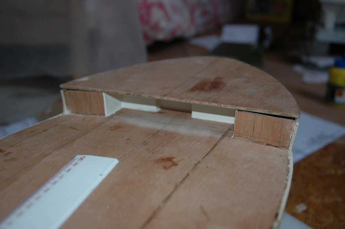
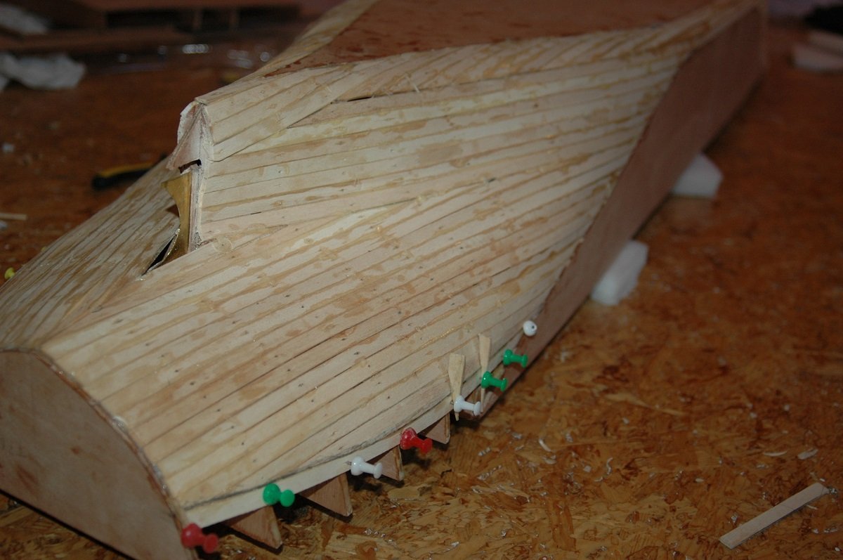
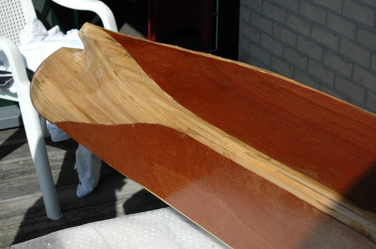
Here things got a bit fuzzy. Seems I finished that aft planking first. I believe I then put balsa blocks on the bow and near the prop shaft and then finished the part underneath the forecastle, since I wouldn't be able to reach it when the forecastle deck was in place. As mentioned before, I had started some major block construction in parallel (while the glue was drying on the planking I suppose). The front of the superstructure is just there for strength. Cutting all the windows from a 2mm thick piece of styrene is pretty hard, so I decided to make a false cover first, to maintain strength and then put a 1mm detailed cover in front. It's quite a piece, but it also had to be removable as it would give access to the motor and speed controller, so it had to be sturdy. Everything on those vessels is concentrated in 1 superstructure (apart from the cargo handling gear), so it also carries the funnel as well as the lifeboats and davits.