yvesvidal
-
Posts
3,639 -
Joined
-
Last visited
Content Type
Profiles
Forums
Gallery
Events
Everything posted by yvesvidal
-
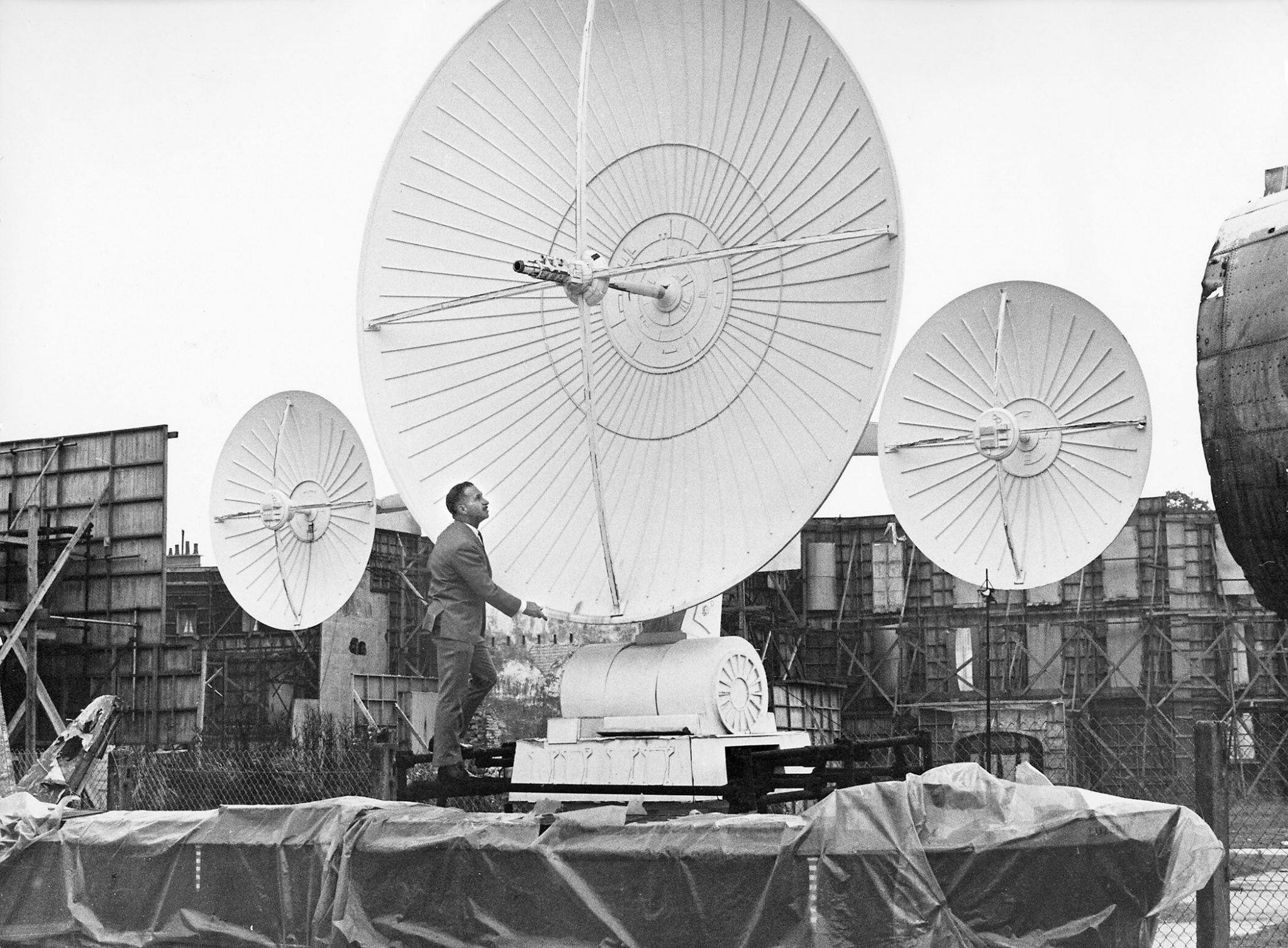
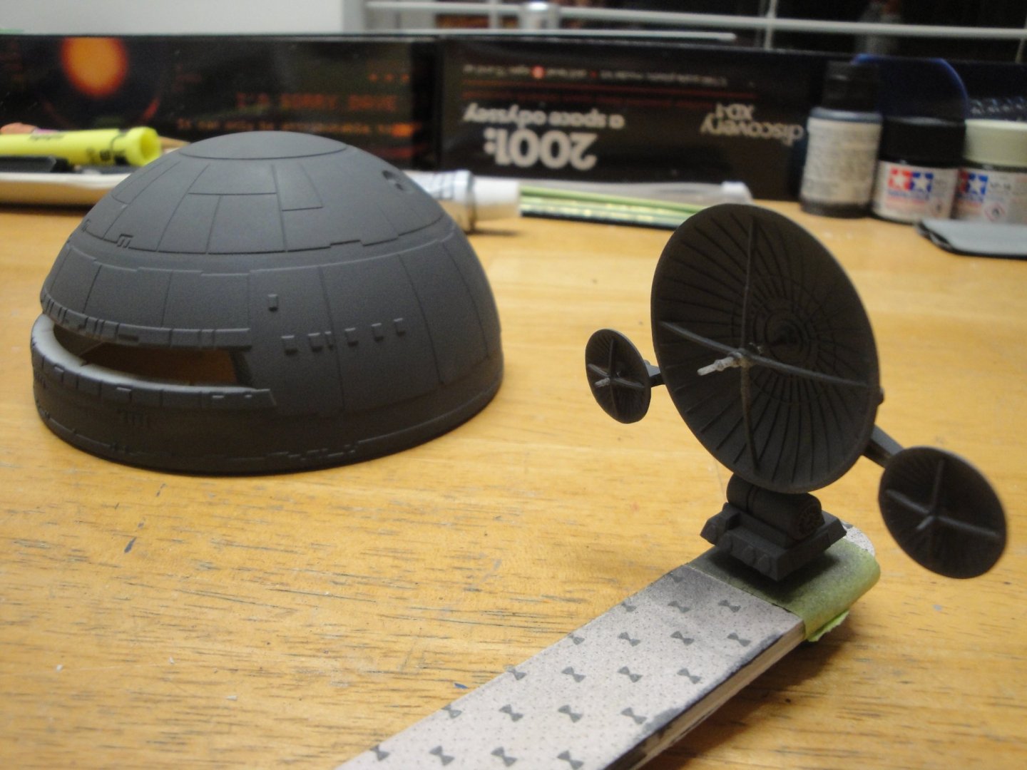
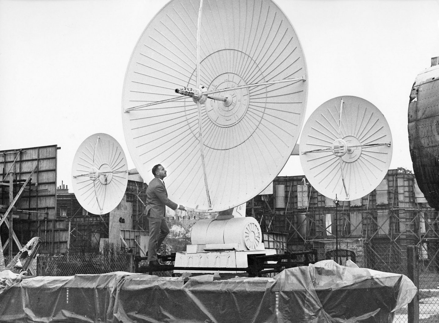
 In parallel to the building of the frame to display the model, I am starting the antennae module, containing the infamous AE-35 device that is the reason HAL 9000 invokes to terminate the astronauts aboard the Discovery: The parts are very delicate and the main cross was broken in my box. A coat of German Grey before applying the white color on top. Below is a picture of Stanley Kubrick, inspecting the original antennae prop built for the 2001 Movie: Yves
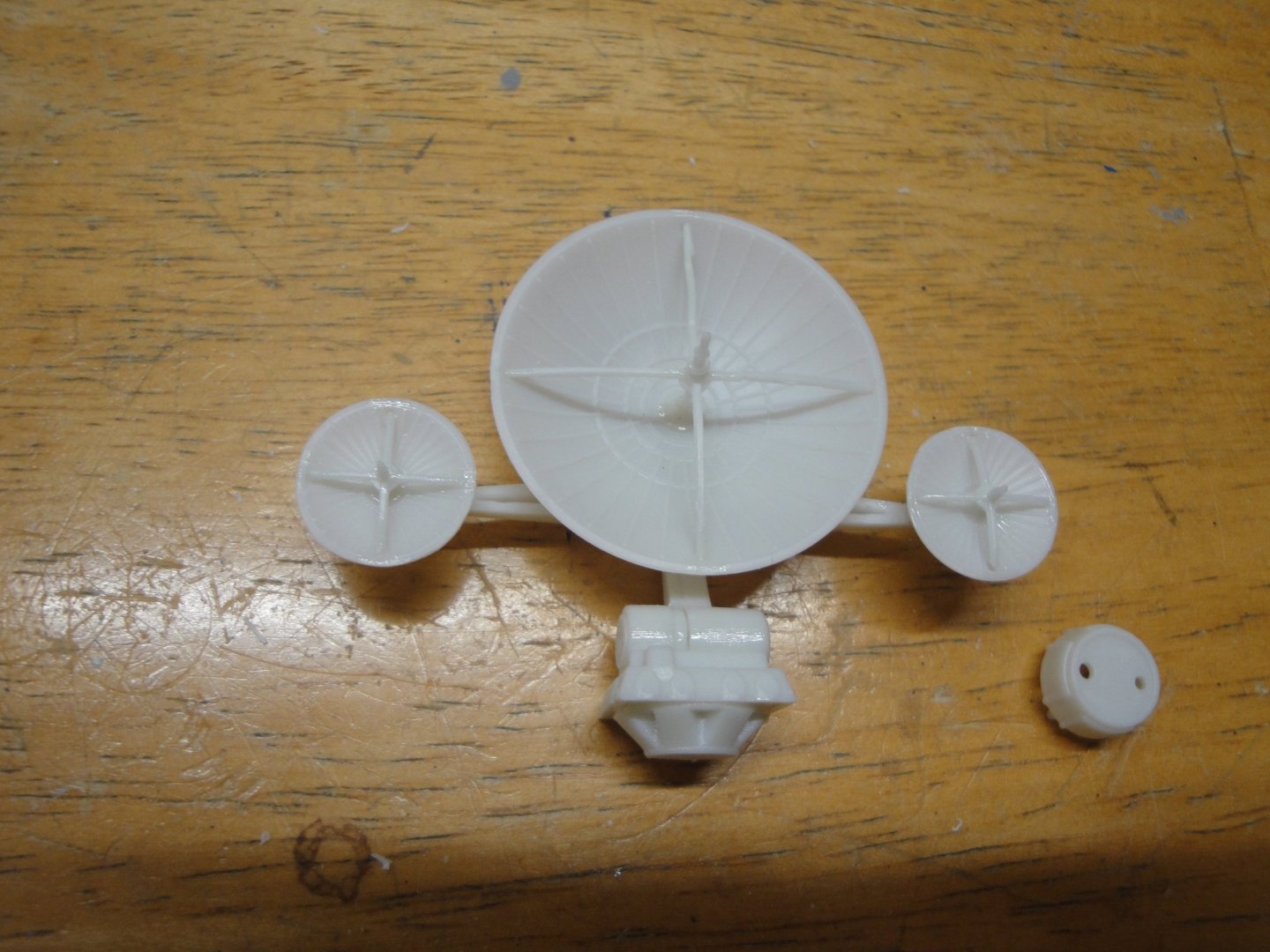
- 119 replies
-
- 12
-

-
All these round shapes do not make the planking easier.... You are doing a good job on that delicate part of the construction. Yves
-
Beautiful. Yves
-
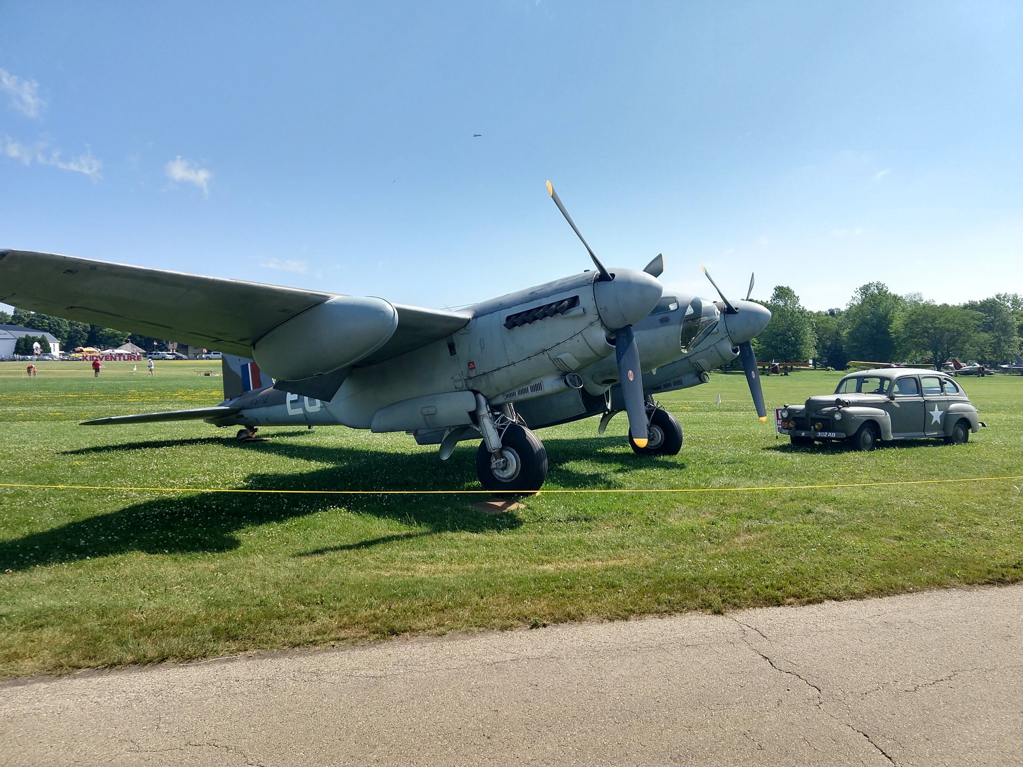
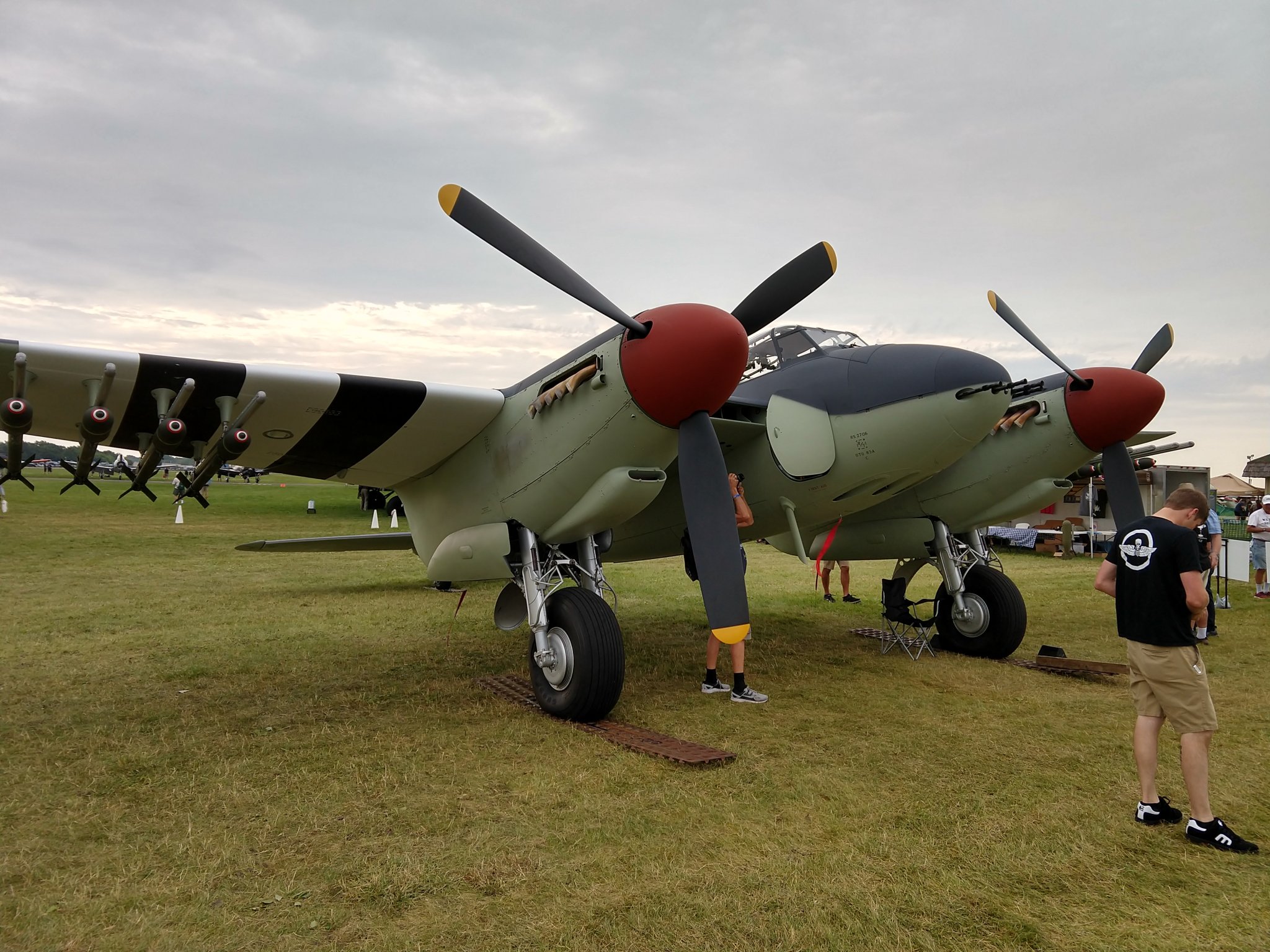
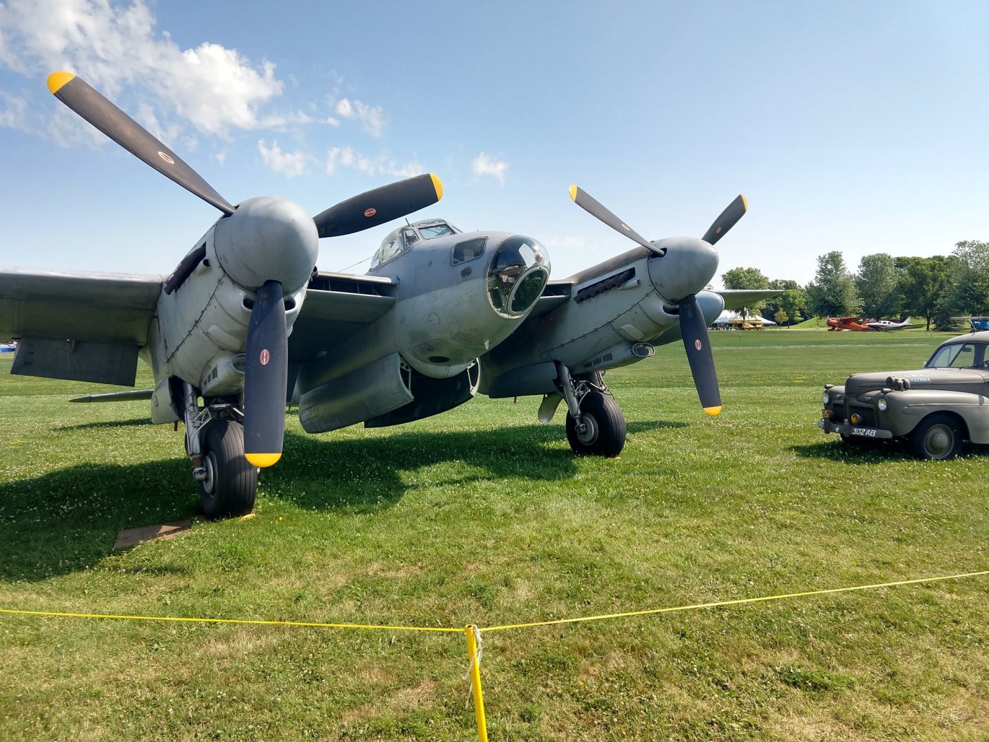
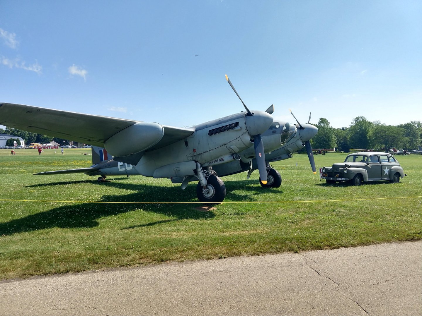
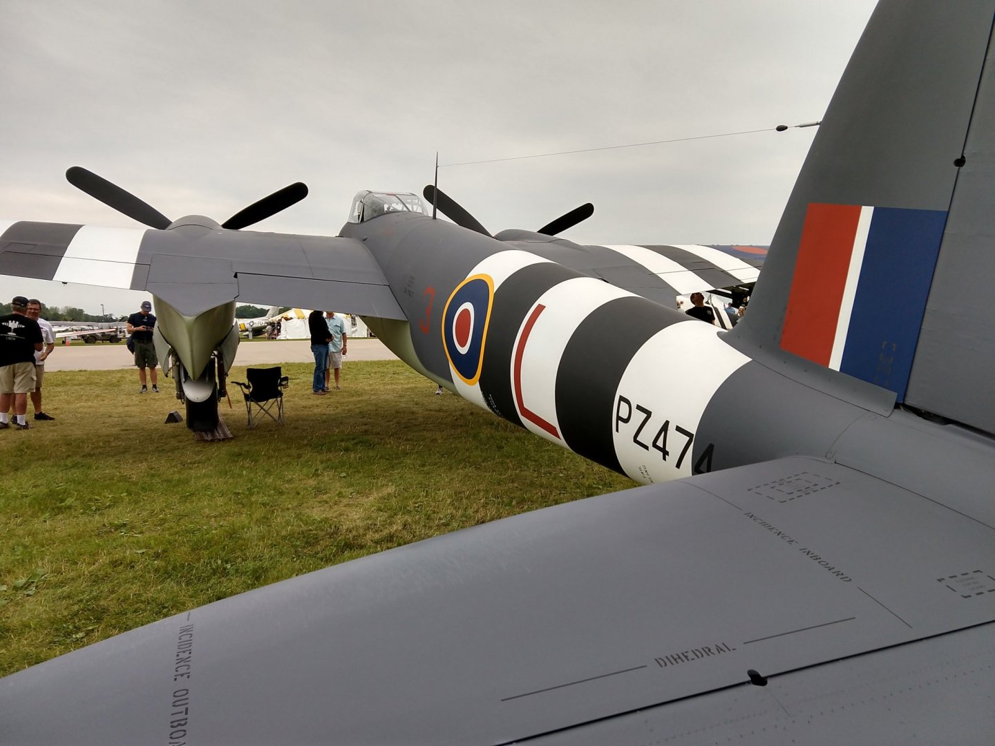
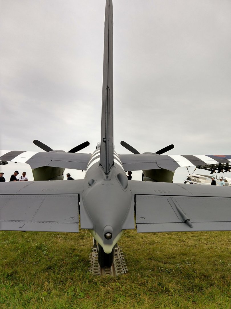
Old Collingwood, here are a few pictures of the two Mosquitoes that were on display (and flying) at the past 2019 Oshkosh airshow. An incredible machine and so elegant in flight: Yves

- 932 replies
-
- 11
-
-
So, you are testing the water with a scratch build, before going for the big challenge? Very good idea. Yves
-
Very nice model. I love the theme that you gave it....naughty and spicy, for great evenings and nights! Are you planning to place some figures, men in elegant suits and ladies in long dresses? Yves
- 18 replies
-
- 1
-
-
- chaperon
- model shipways
- (and 1 more)
-
This is a fully rigged vessel, for sure. Thank you for explaining to us what each line is used for. I find that very useful. Yves
- 315 replies
-
- 2
-
-
- master korabel
- avos
- (and 1 more)
-
Nice collection of ships on your bench. Congratulations. Yves
- 171 replies
-
- 1
-
-
- artesania latina
- bounty
- (and 1 more)
-
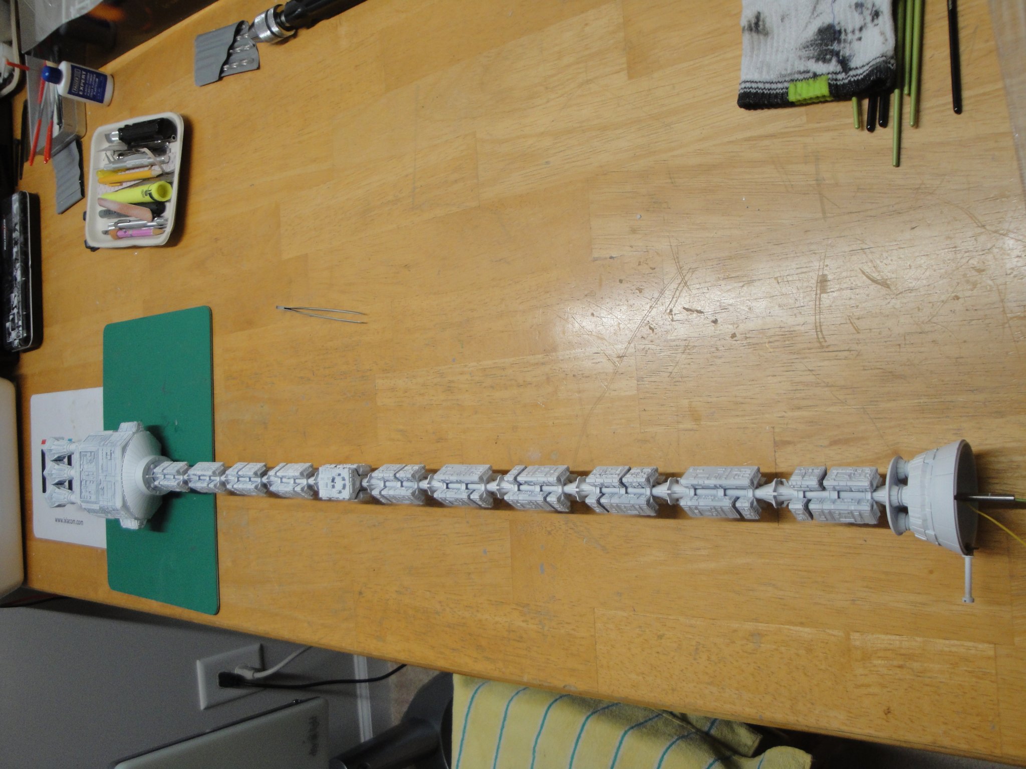
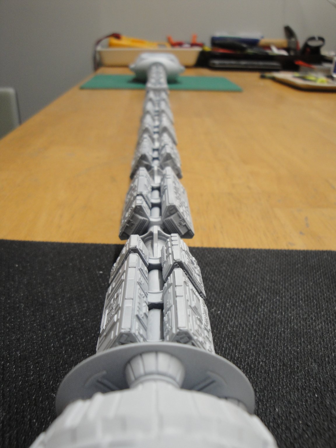
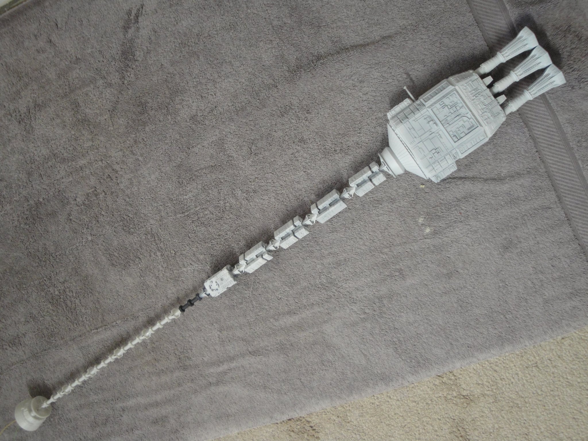
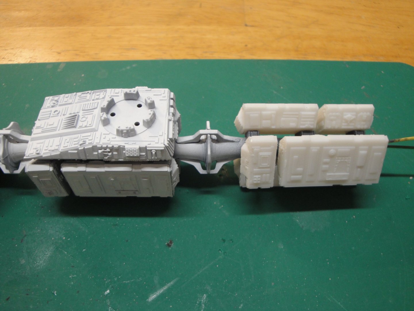
A major milestone has been attained: front and rear spines have been connected to each other: It does not sag too much. Obviously, this brass piece of tube, helps tremendously. I can actually hold the ship from the propulsion block without much noticeable sagging. Of course, once the living quarters (Sphere) will be in place, it will be another story: I am now going to start working on the frame, used to display the model, and will try to finish the front electrical connections, so that I can close the lid on the front section. Yves


- 119 replies
-
- 13
-
-
Thank you Popeye. I hope that my whole anchoring idea is going to work.... 3 mm times two, should do the trick.... crossing my fingers. Yves
-
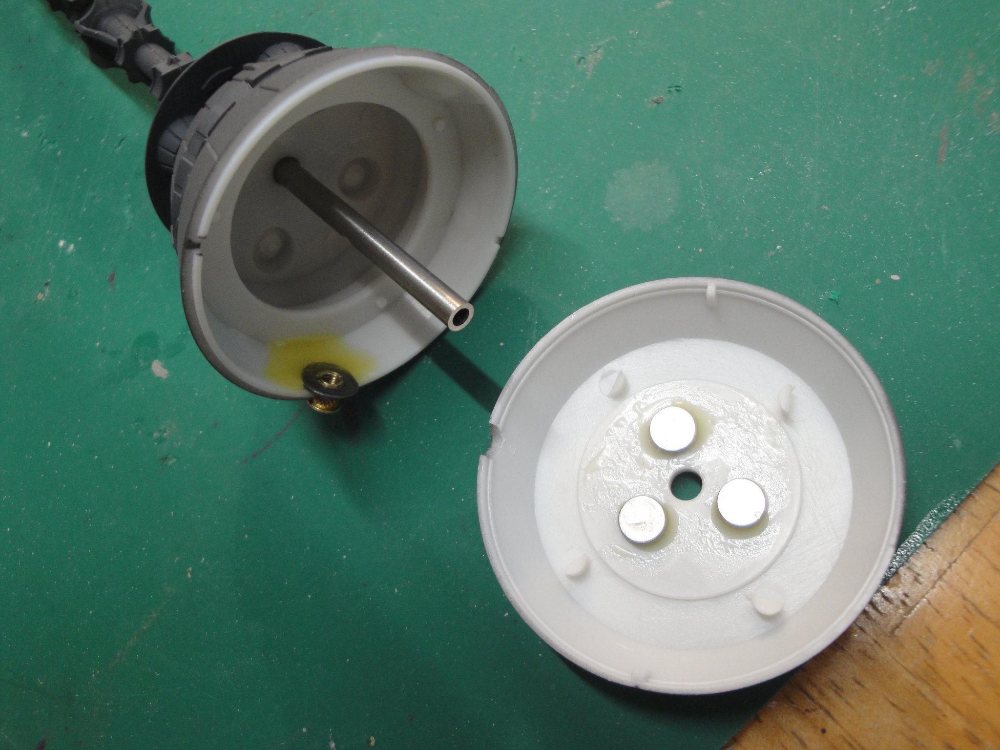
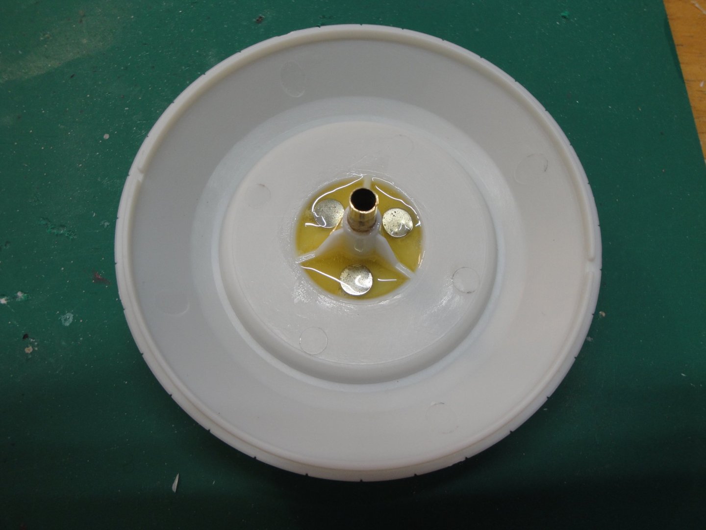
Popeye, the sphere will be unglued from the rest of the vessel. The ship will rest horizontal, and with the magnets, the tight fit of the copper tube on the steel rod and the three little plastic prongs, the Sphere/Living spaces should hold decently. In addition, there will be electrical wires....so I am pretty confident, it will stay in place. Yves
-
No, that would not make it: front and rear would be sagging.... These tubes, although made of steel, are somewhat flexible. Yves
-
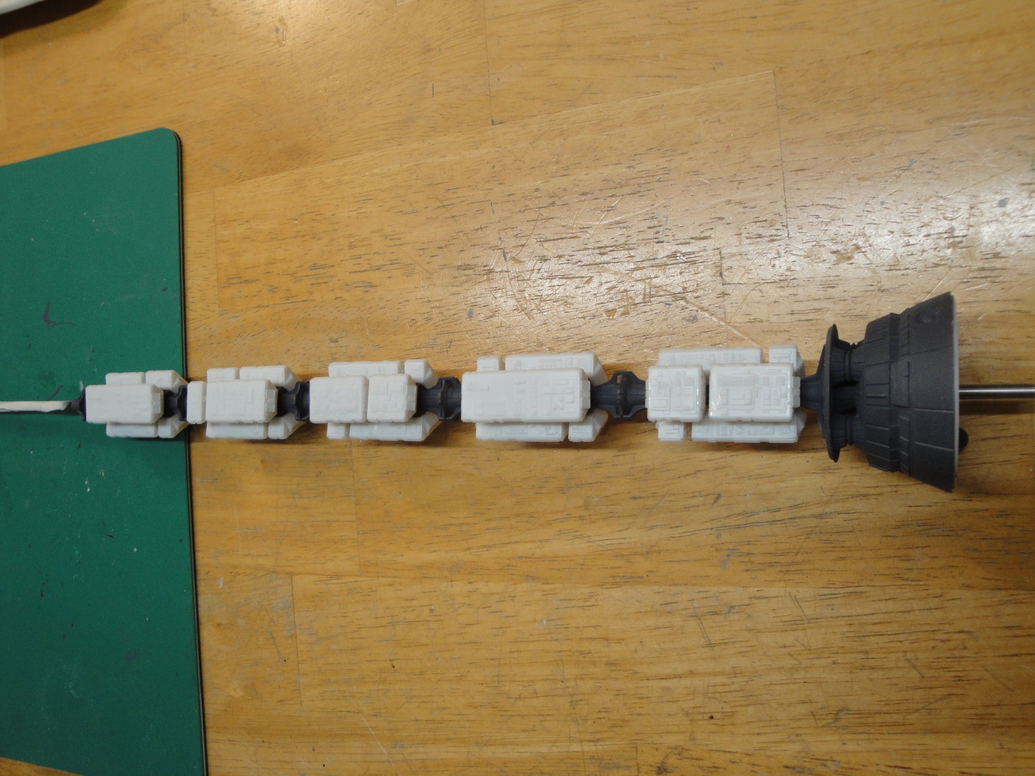
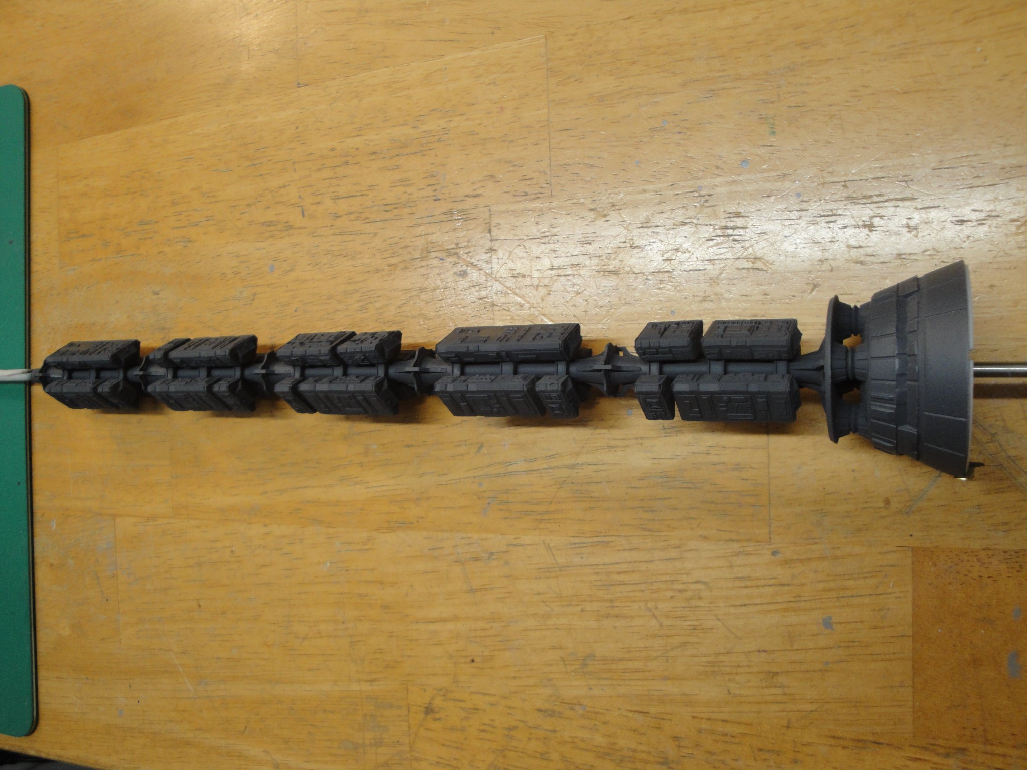
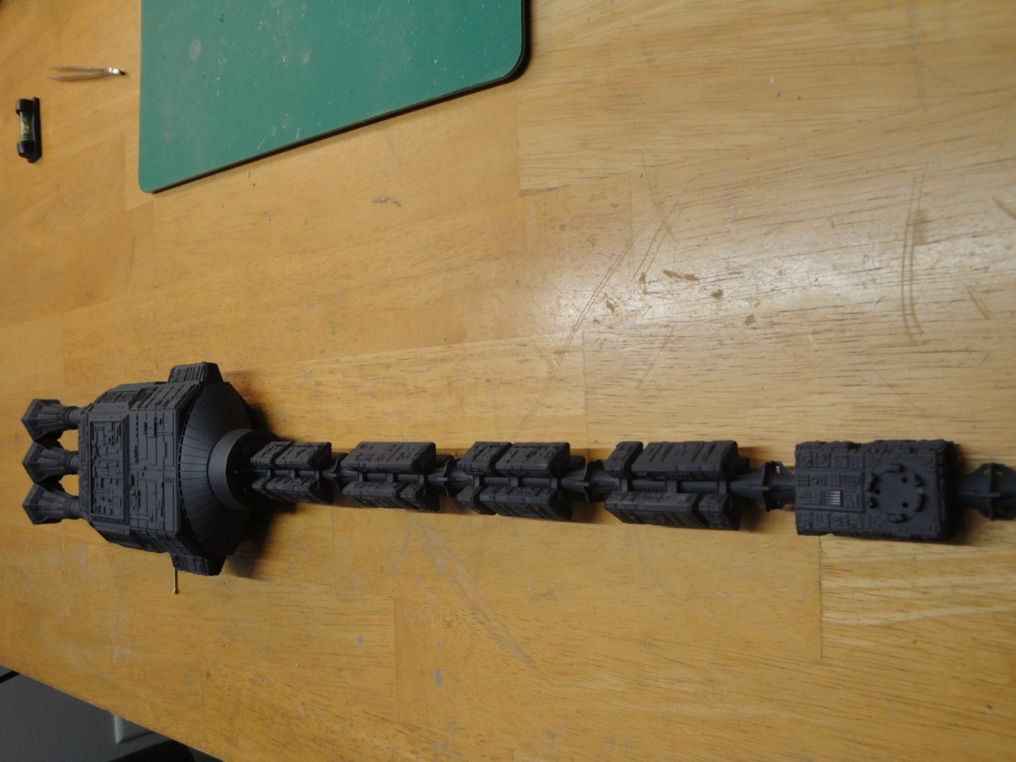
Still working on the forward spine. First, some Primer (Vallejo): Details of the anchor and electrical feed. The device is glued with epoxy two components for extra strength. Once the lid (right) is closed, it will not be possible to access the wires and anchor nut: I just finished assembling the some 30 PODs required for the front spine.... Slightly boring, but not too bad overall. In this picture, you can see the difference between the plain molded white of the parts and the base coat in dark gray, oversprayed with white. It is worth the extra efforts, for sure. All the PODs are in place and glued to the spine: A heavy coat of dark gray (German Grey) to finalize the whole Kebab: Yves


- 119 replies
-
- 13
-
-
Fantastic work! Could you elaborate a little bit on that kit ? CAF ? Grazie mile. Yves
-
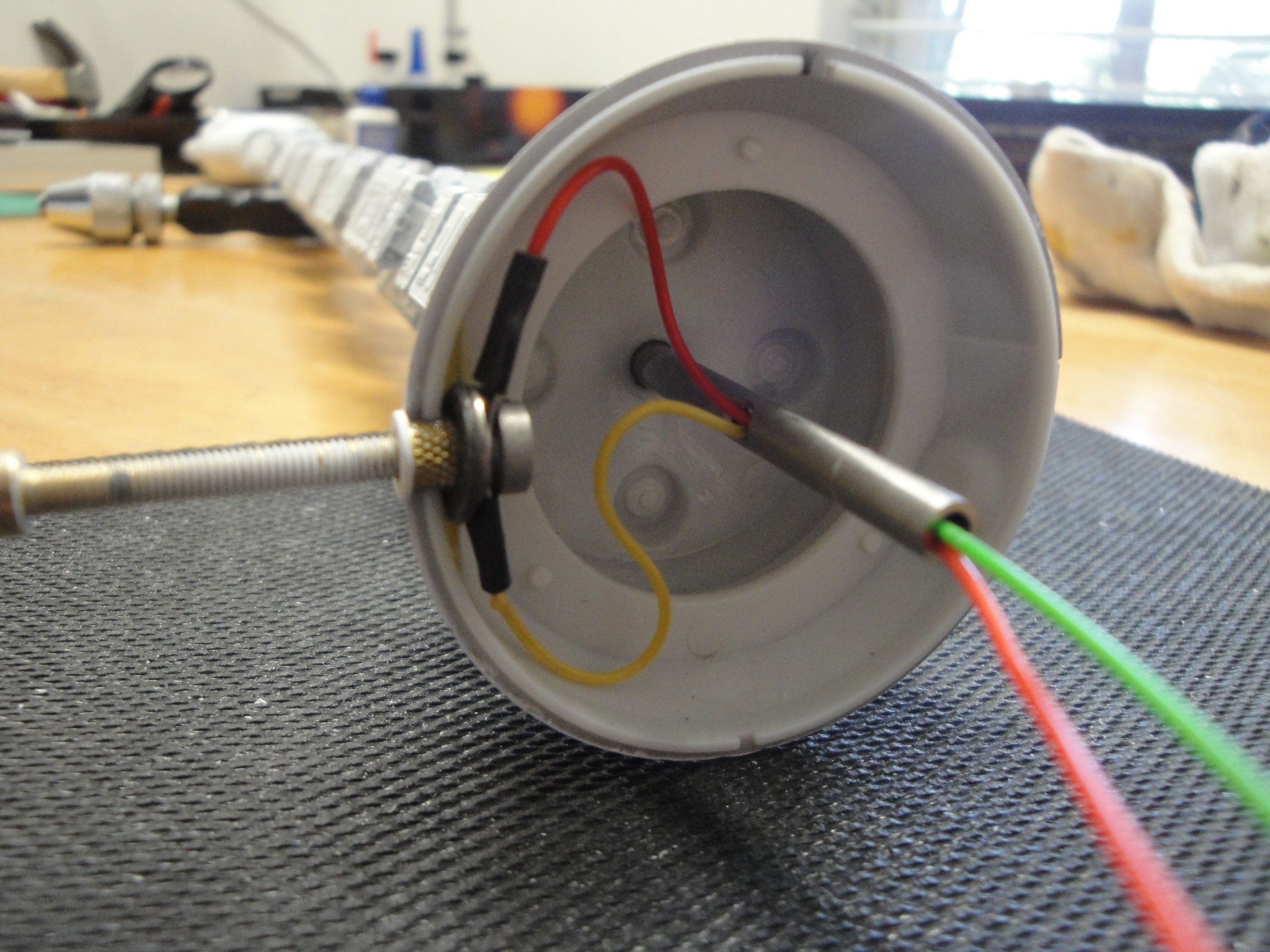
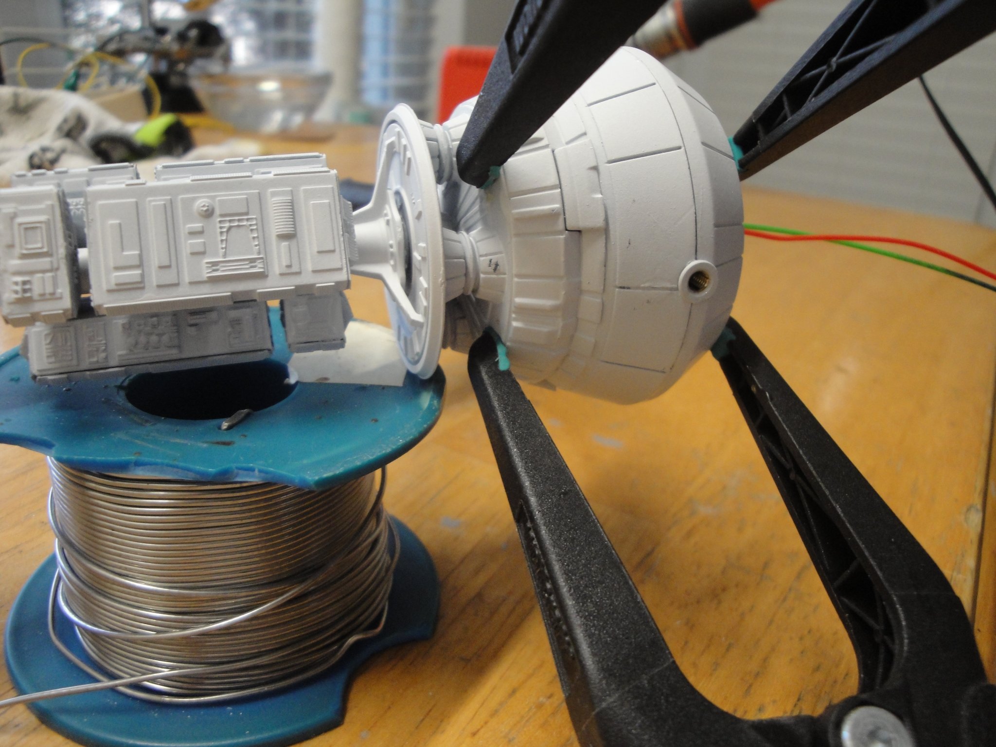
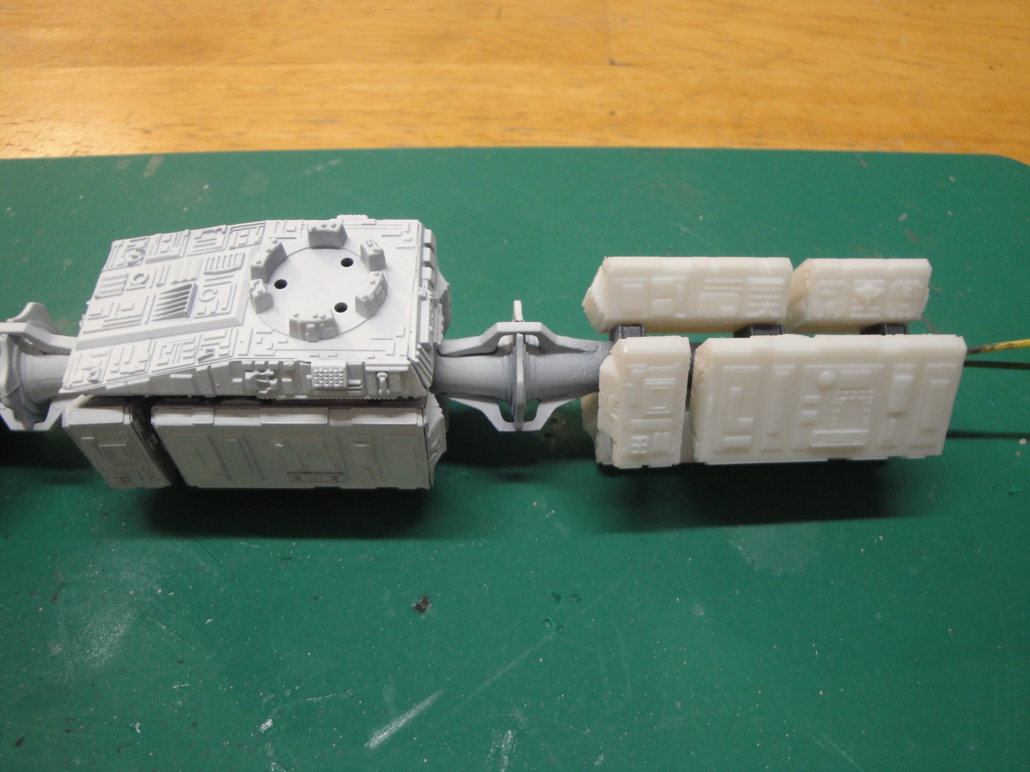
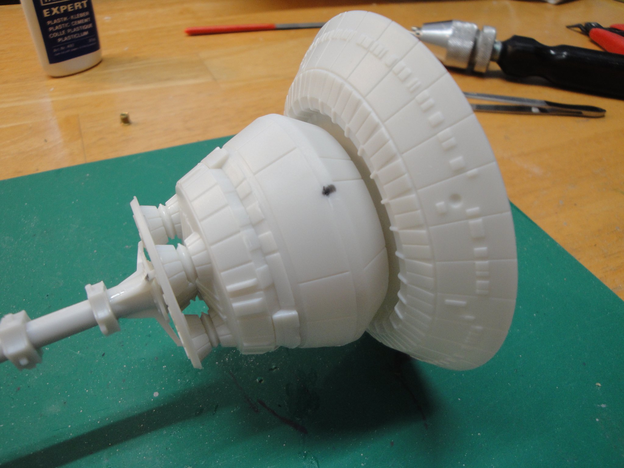
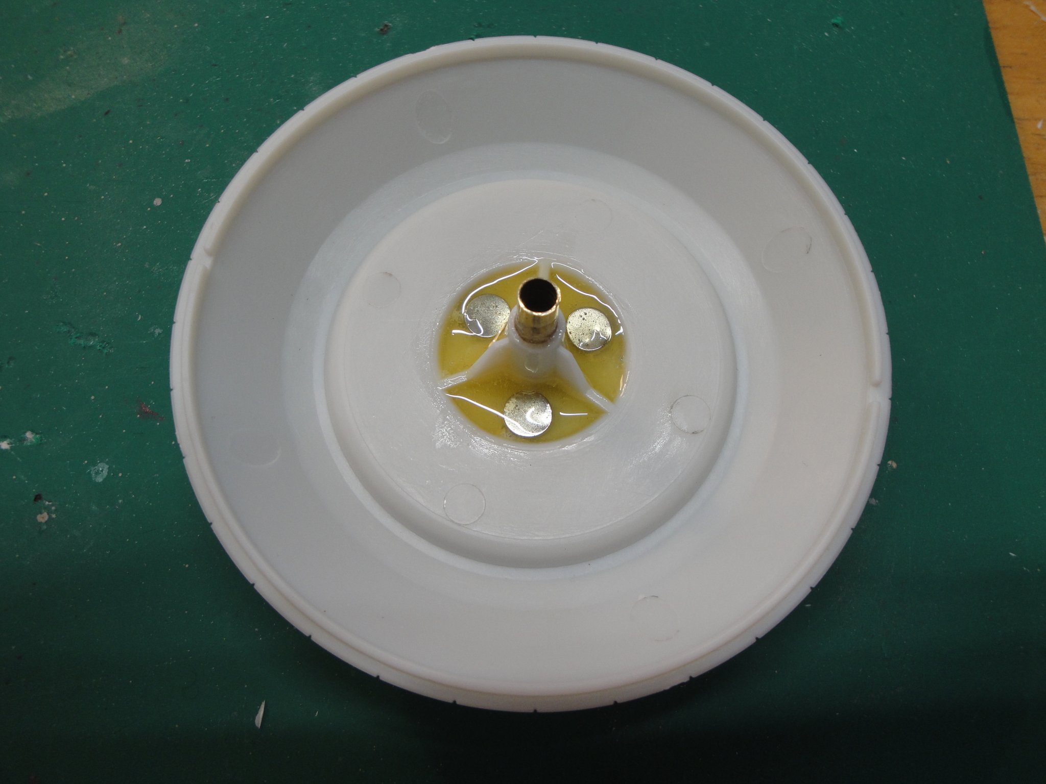
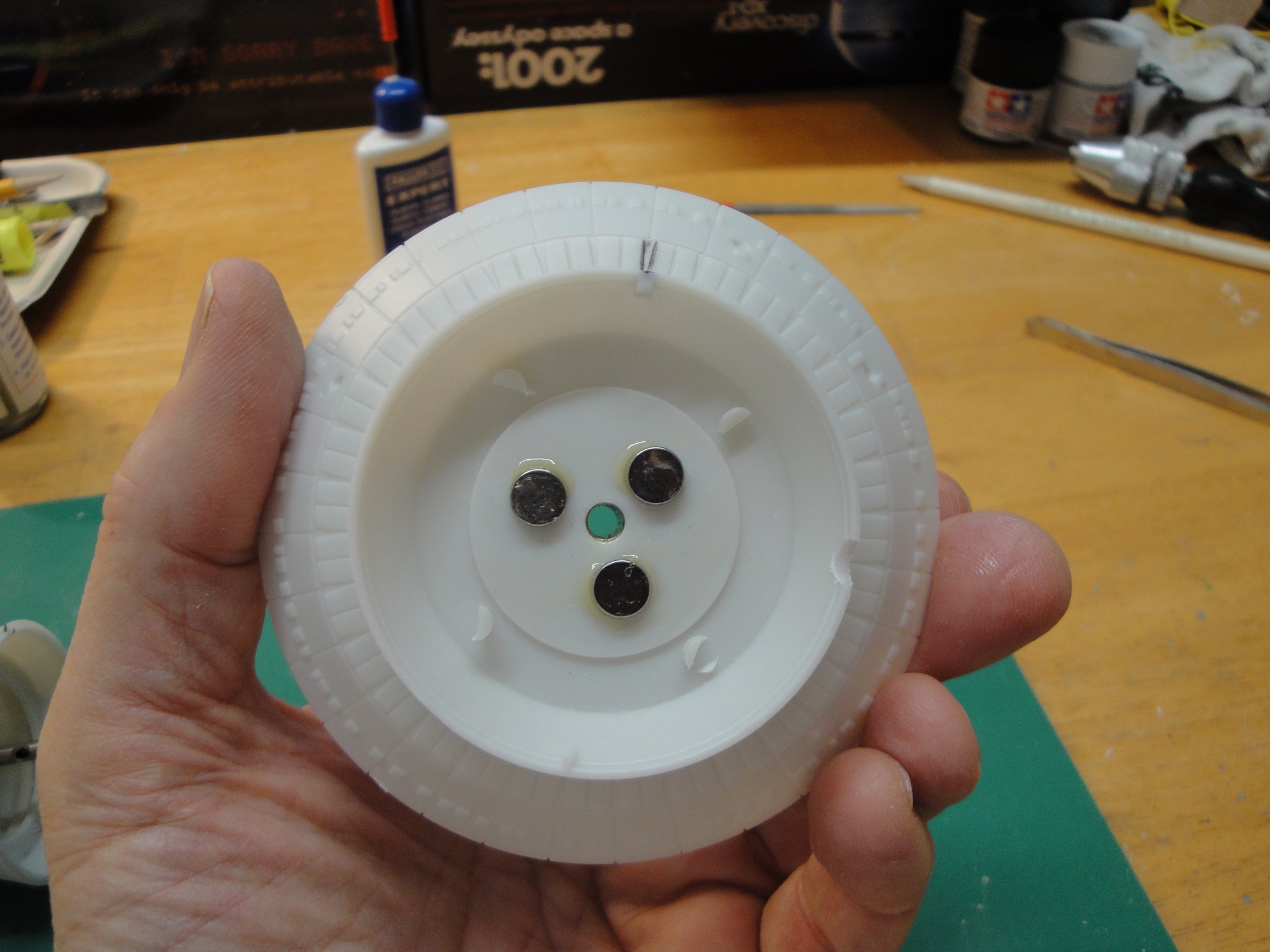
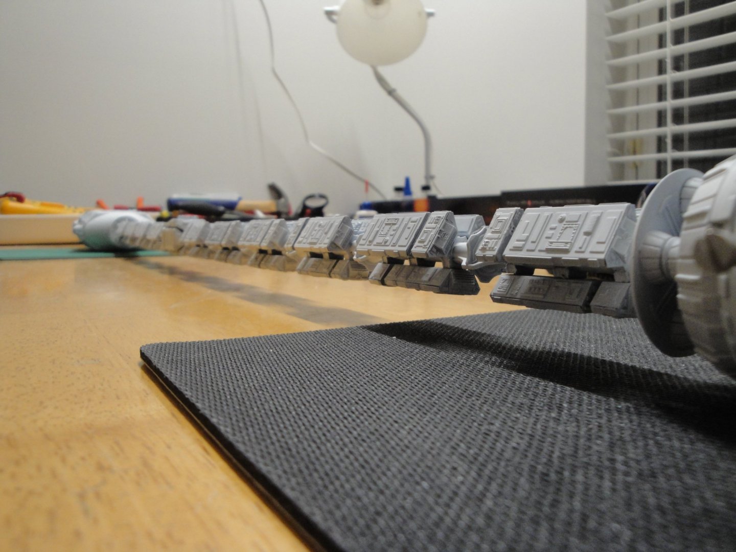
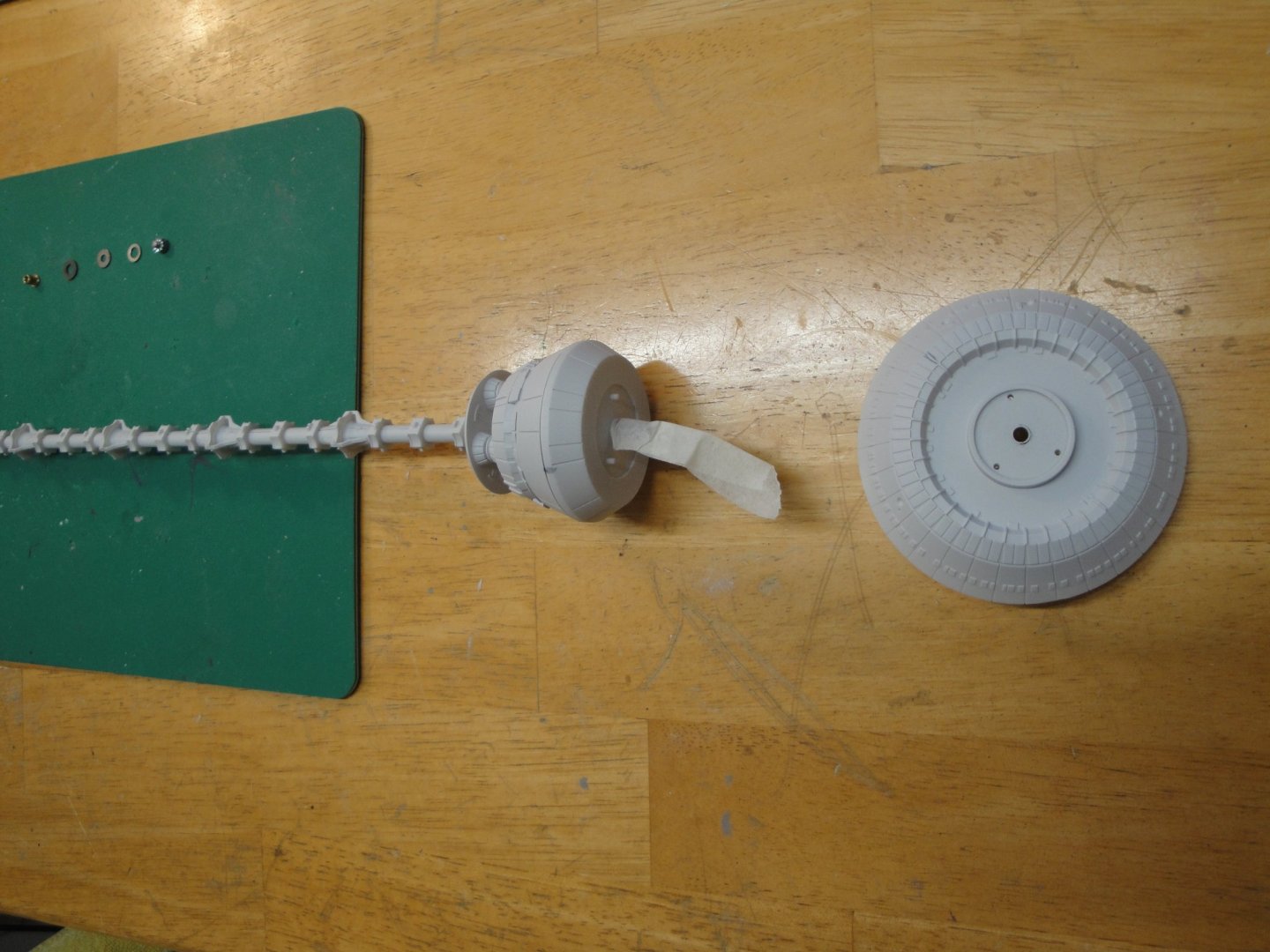
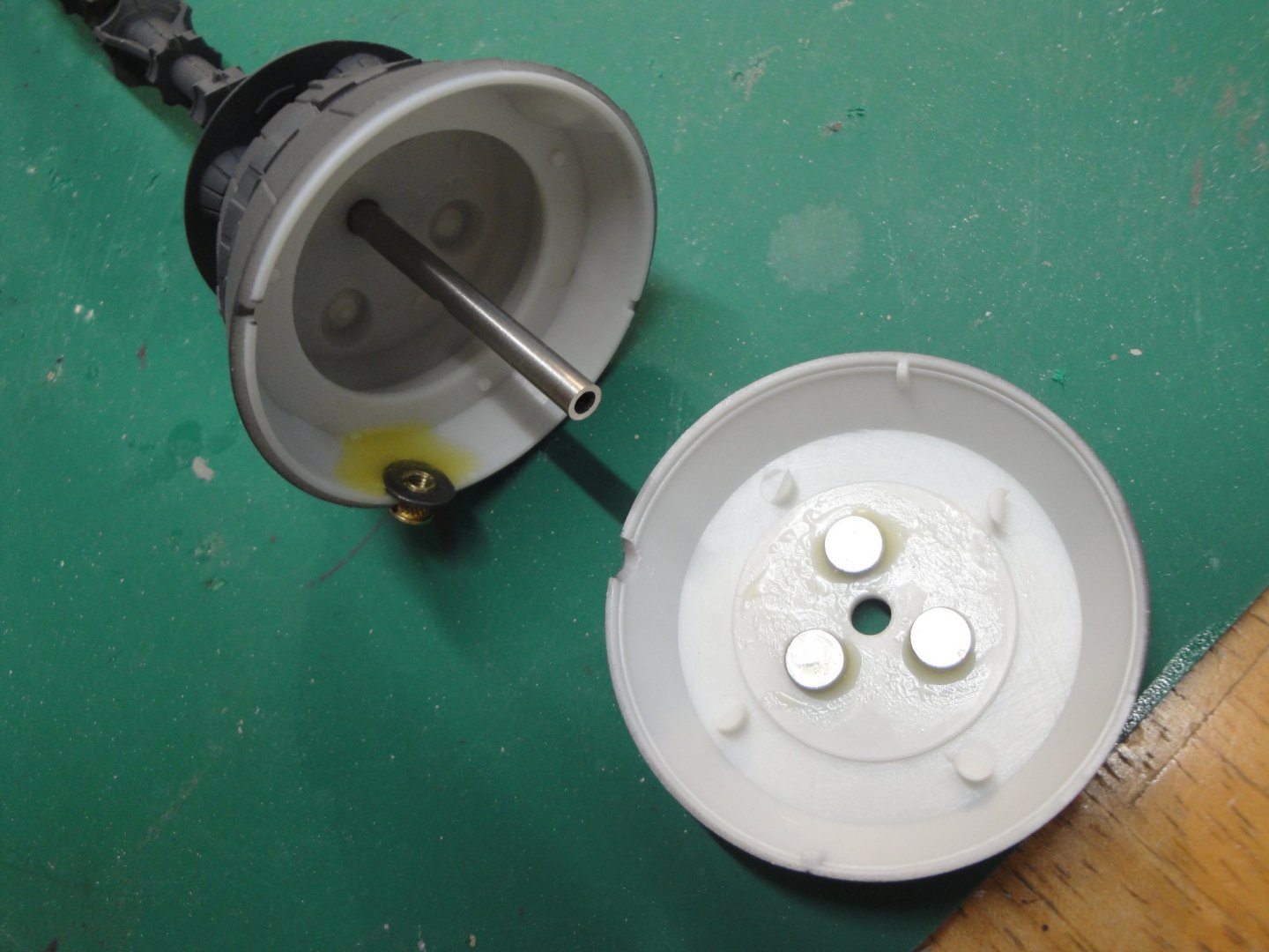
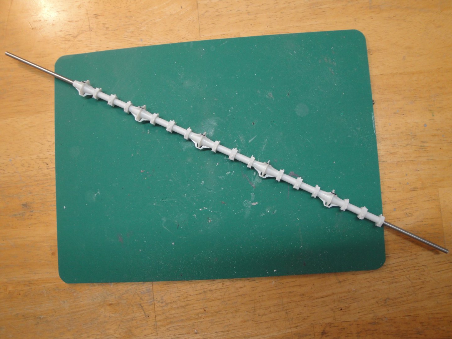
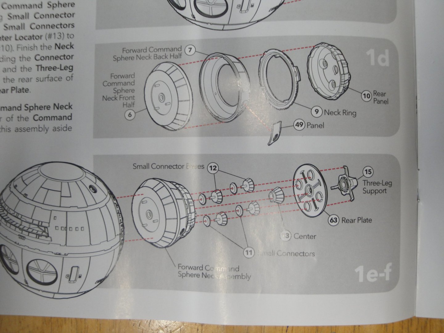
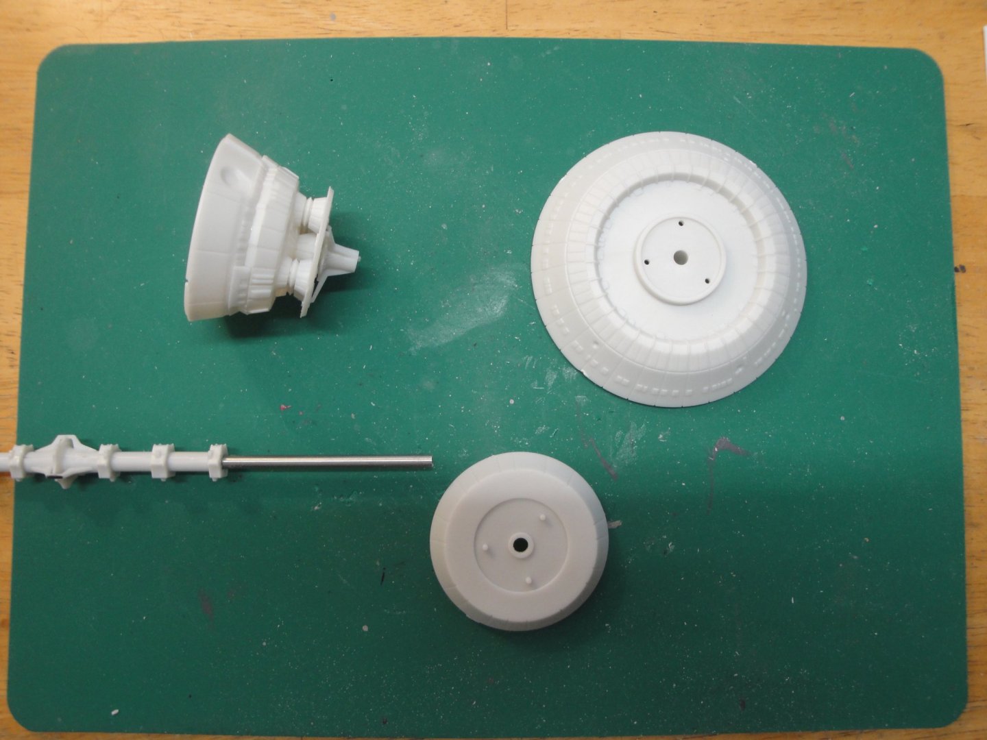
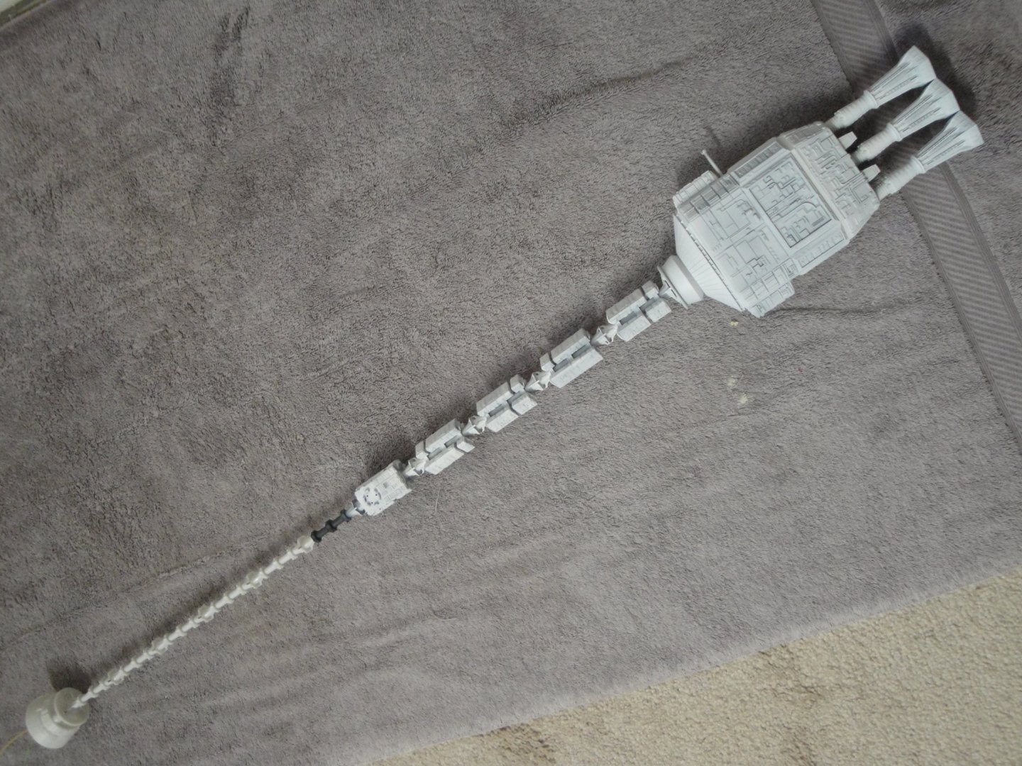
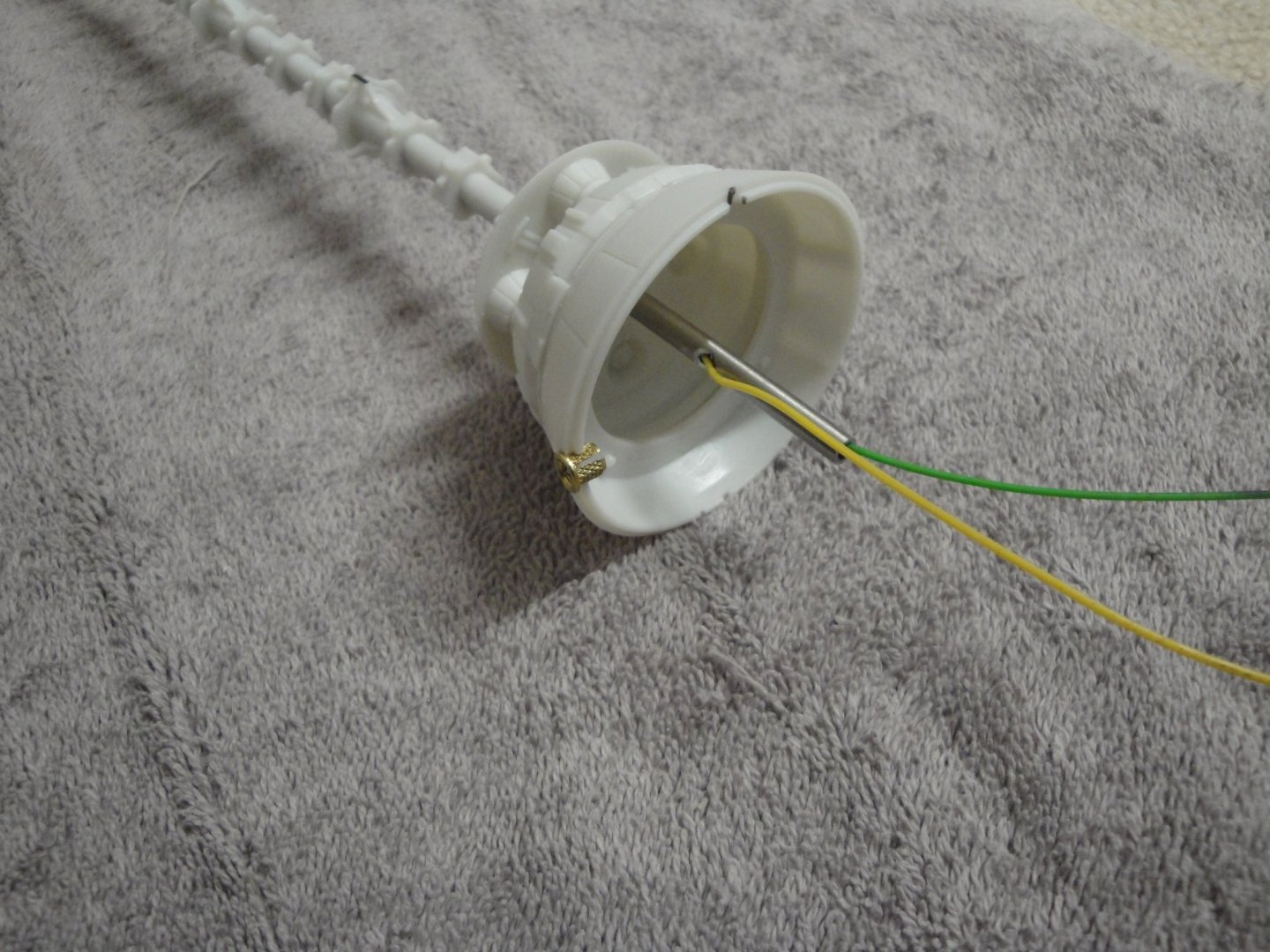
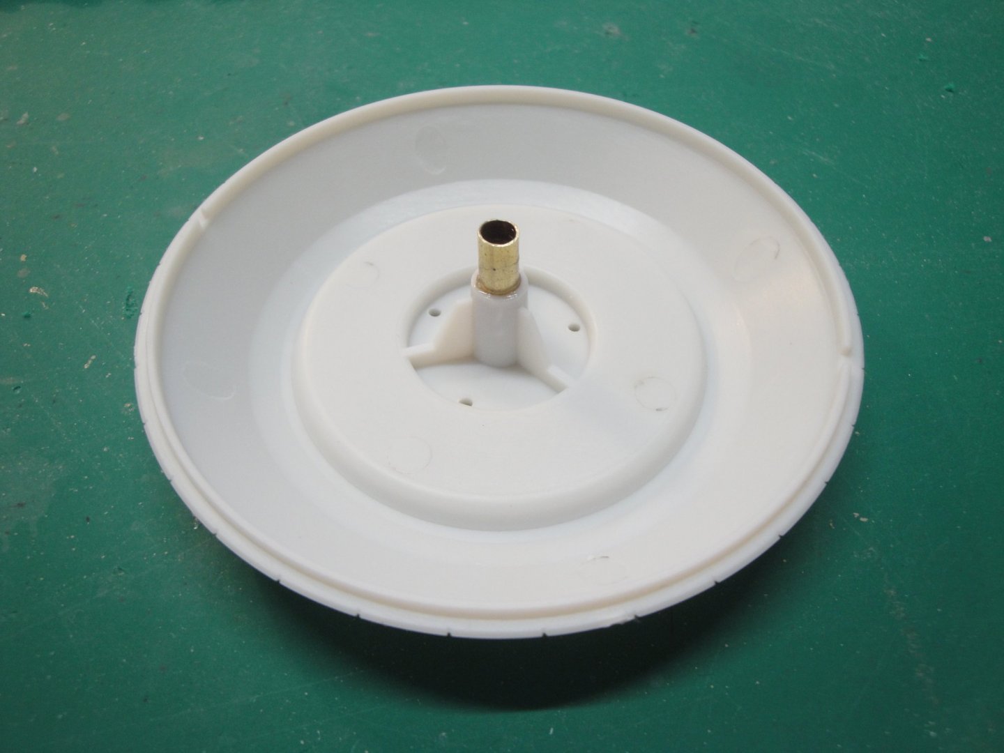
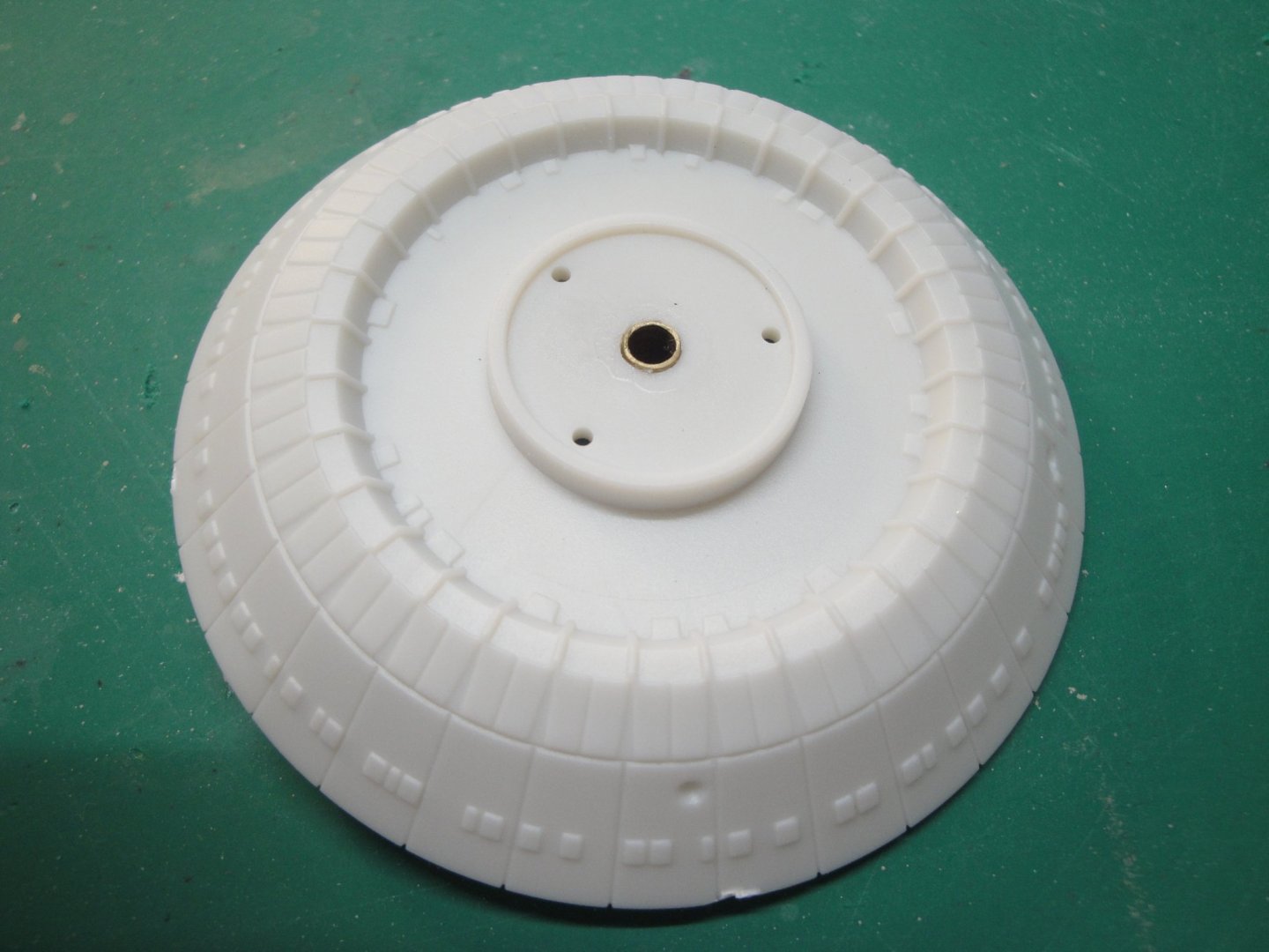
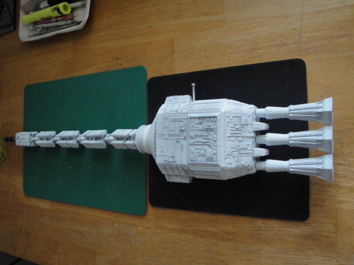
With the rear spine completed, it is now time, of course, to start working on the front spine: The forward rod is put in place in the central module and inserted all the way into the brass tube. Fitting is perfect and very tight. Then, the PODs holder modules are placed and carefully glued. Finally the forward spine is removed from the Central module and the rear section left aside. It is simply not practical to work on the entire vessel as it is far too long and too fragile. It is then time to start assembling the anchor of the living spaces, the main sphere and unique landmark of this vessel: And this is where we stand: The whole vessel is starting to come together: it is really long and so skinny... Seeing a picture of Discovery or watching the movie is one thing. Holding that skeleton of model is another.... It is quite unique. The electrical wires are driven through the spine and the positive side of the circuit will be connected to the second side holder. The holder is a 3 mm special brass nut designed to be inserted with pressure into wood or plastic. It will then be glued and secured to the front anchor of the living space. Yellow and green wires will be sent to the sphere for the main deck lights. The rear of the sphere is also receiving a piece of that brass tube to make the alignment of the sphere perfect with the spine and to prevent any sagging. The sphere is going to be heavy with the PE decks and lights. Besides, it is a massive piece of polystyrene. Here is what it will look like: For the time being, I want to be able to dissociate the sphere from the spine. This is done to work more easily on the background and holder and to allow me more flexibility with the inside building and painting of the sphere. Again, I am using my miniature rare earth magnets and their terrific sticking power to secure the rear section of the sphere with the spine: That section (below) will be tied to the spine, whereas the section (above) is the rear section of the sphere. Yves


- 119 replies
-
- 14
-
-
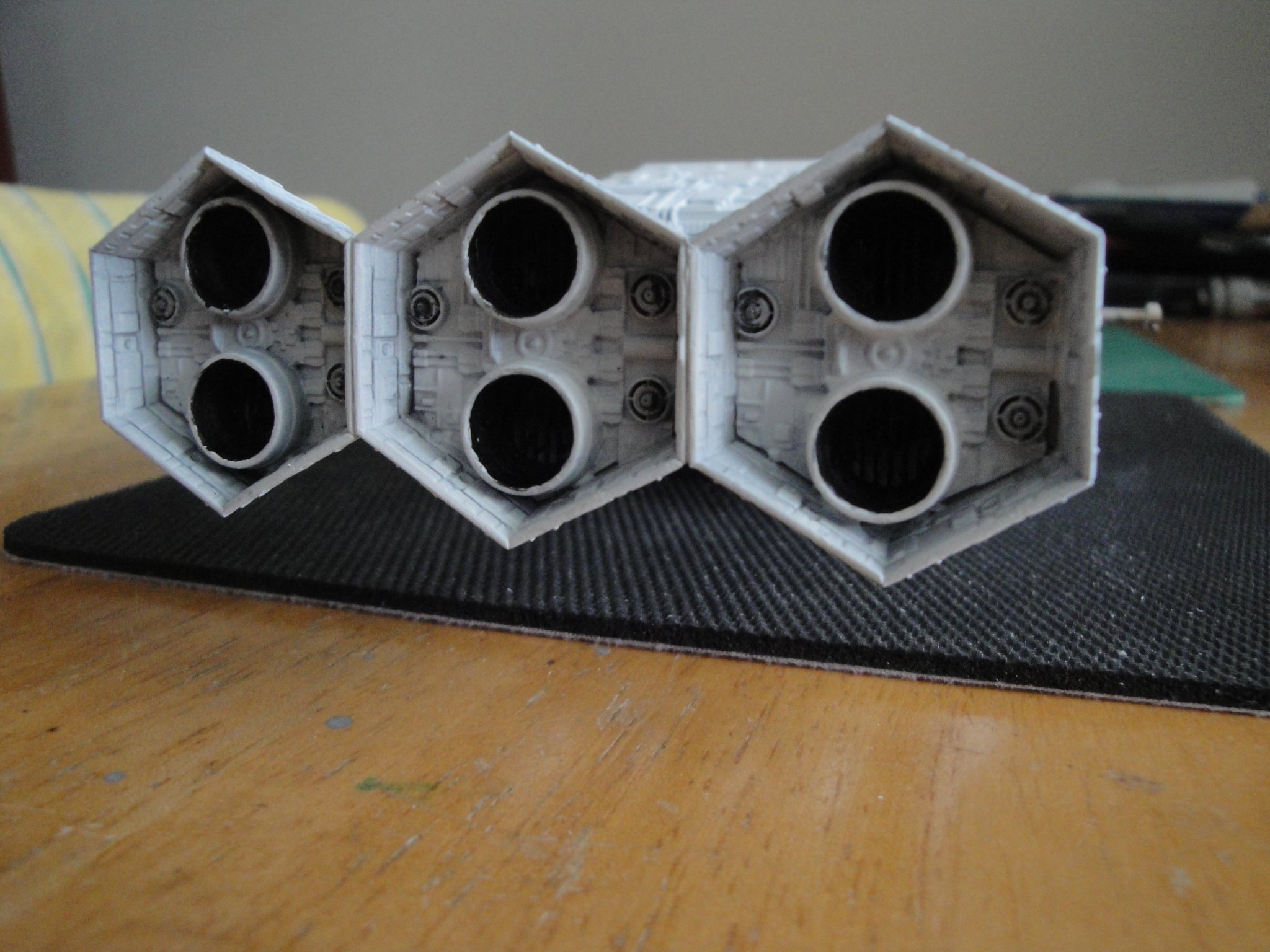
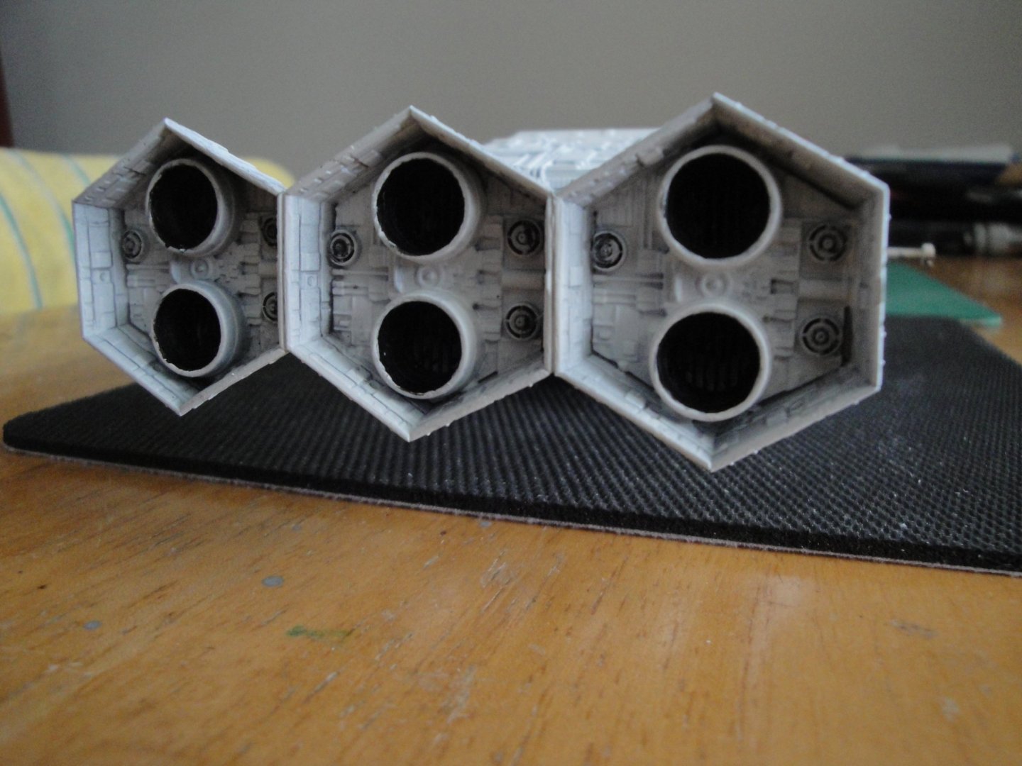
The rear section is now complete. I am quite happy with the white veil, as it remains subtle and allows some of the grayish color underneath to reveal the many details of the pods and propulsion unit: The thrusters are also painted and the inside of the egress ports has been painted flat black: Hmmm... I may have to do very small touch-ups with white on the nozzles.... Yves
- 119 replies
-
- 11
-
-
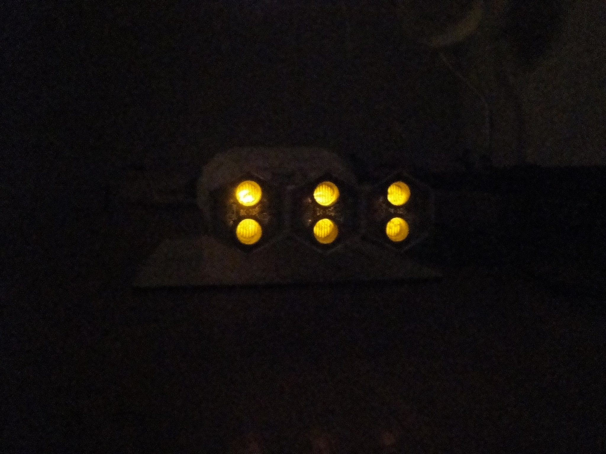
Working on the paint of the propulsion block and on the exhaust of the thrusters. All the pods are painted German Grey as a sub-layer in preparation for the white veil. By the way, if you do not have an airbrush, please don't buy this kit. Impossible to paint otherwise. First veil has been applied. There are significant gaps between the exhaust bulkheads and the enclosure and I am using some white glue to fill up the tiny cracks. It is quite surprising to find issues, as this kit is very well put together. Some tests of the thrusters: The egress ports will be painted black. In the middle of space, far from Earth.... Yves

- 119 replies
-
- 15
-