HOLIDAY DONATION DRIVE - SUPPORT MSW - DO YOUR PART TO KEEP THIS GREAT FORUM GOING! (83 donations so far out of 49,000 members - C'mon guys!)
×


yvesvidal
-
Posts
3,607 -
Joined
-
Last visited
Content Type
Profiles
Forums
Gallery
Events
Everything posted by yvesvidal
-
 Thank you guys for the encouragement and compliments. I truly appreciate every one of them. Yves
 -
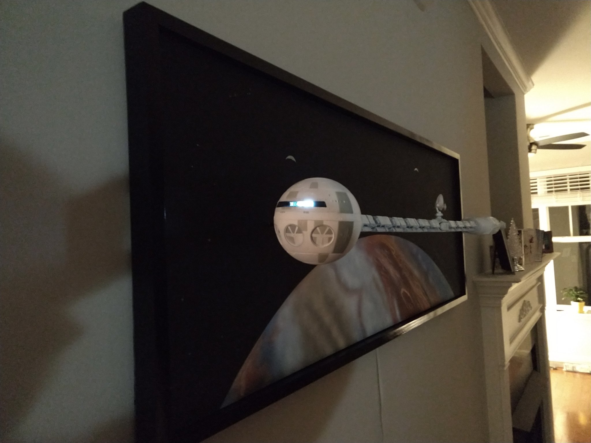
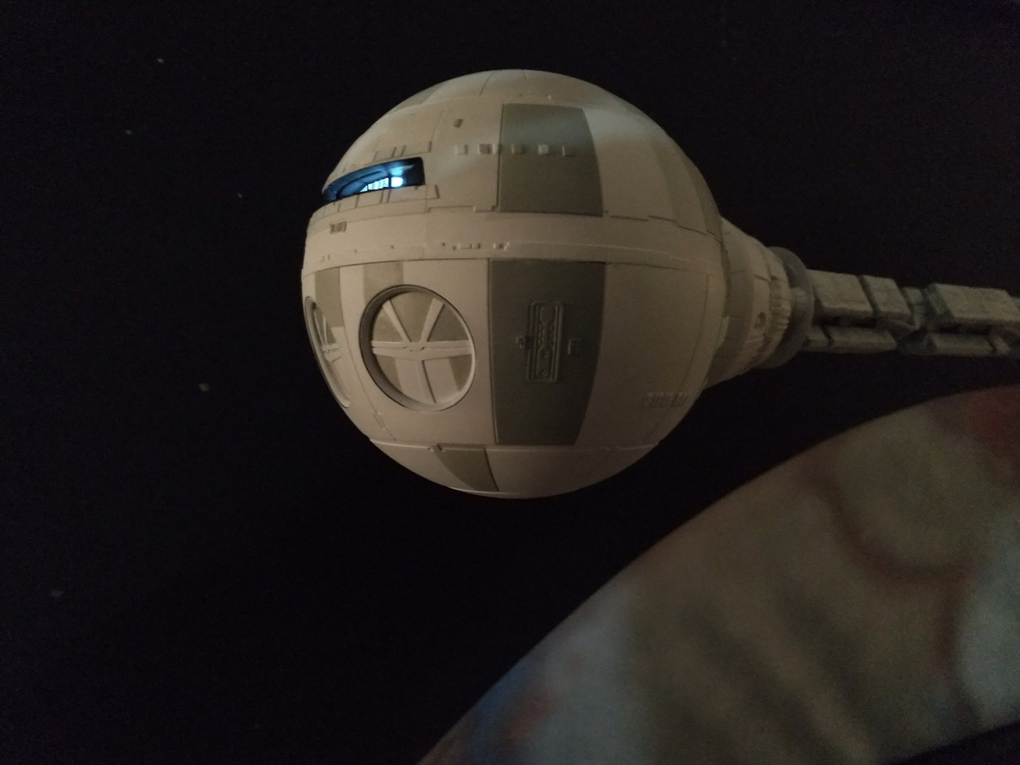
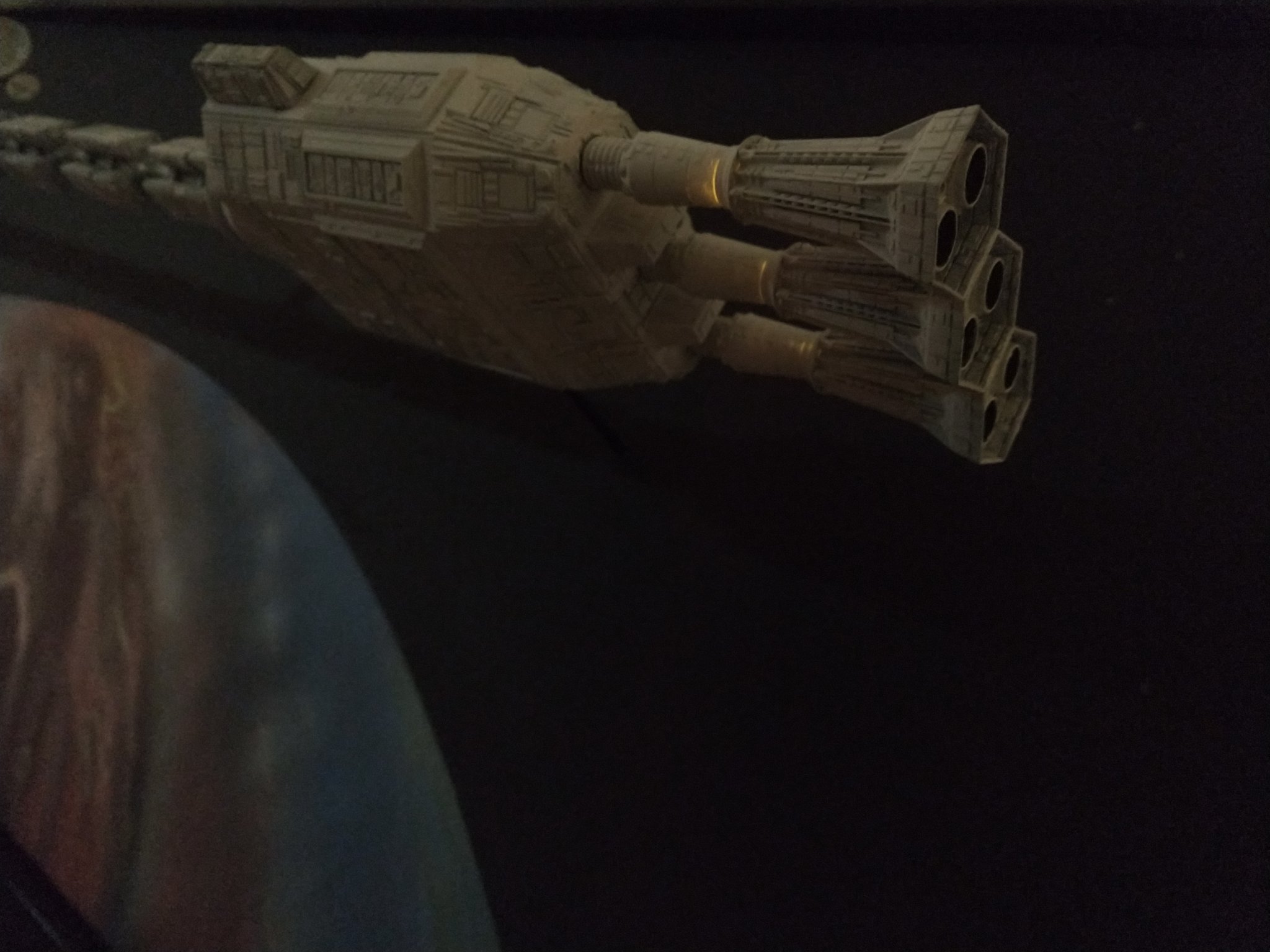
None of the above :-) The Discovery pictures are from my Android phone. Everything about the submarine is from an old Sony camera, unable to focus at short distance. Yves
-
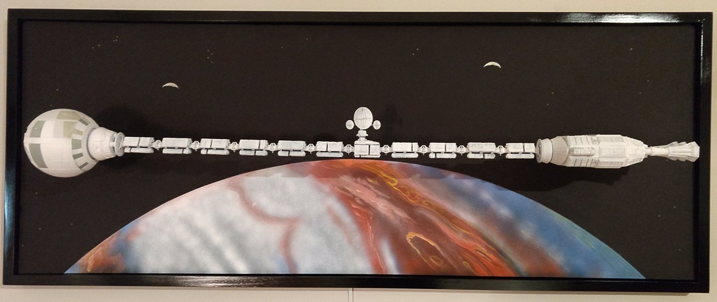
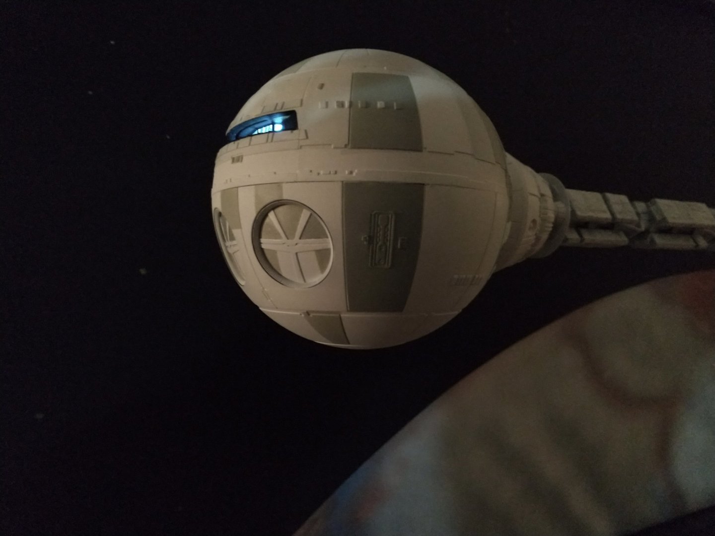
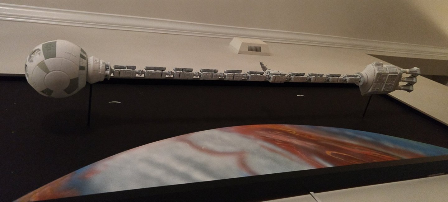
Well, the deep space "submarine" Discovery XD-1 is now completed: It will be a little while before I go back to the U-Boot but who knows..... the urge may come back, quickly. Yves
- 760 replies
-
- 17
-

-
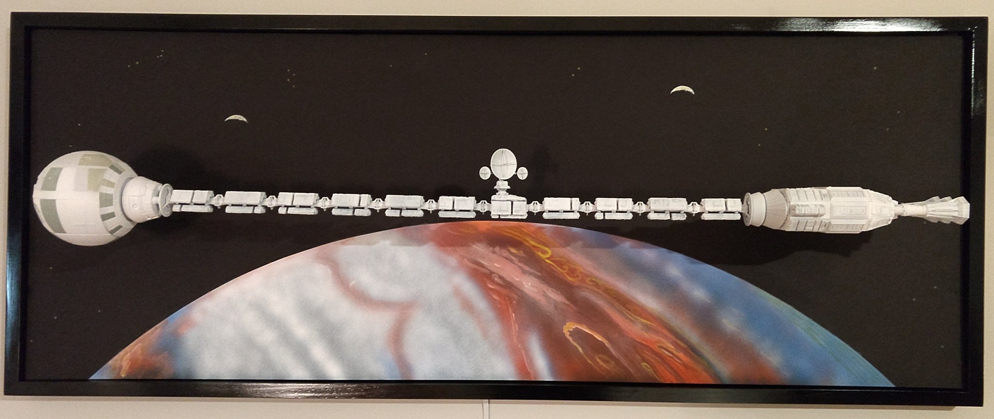
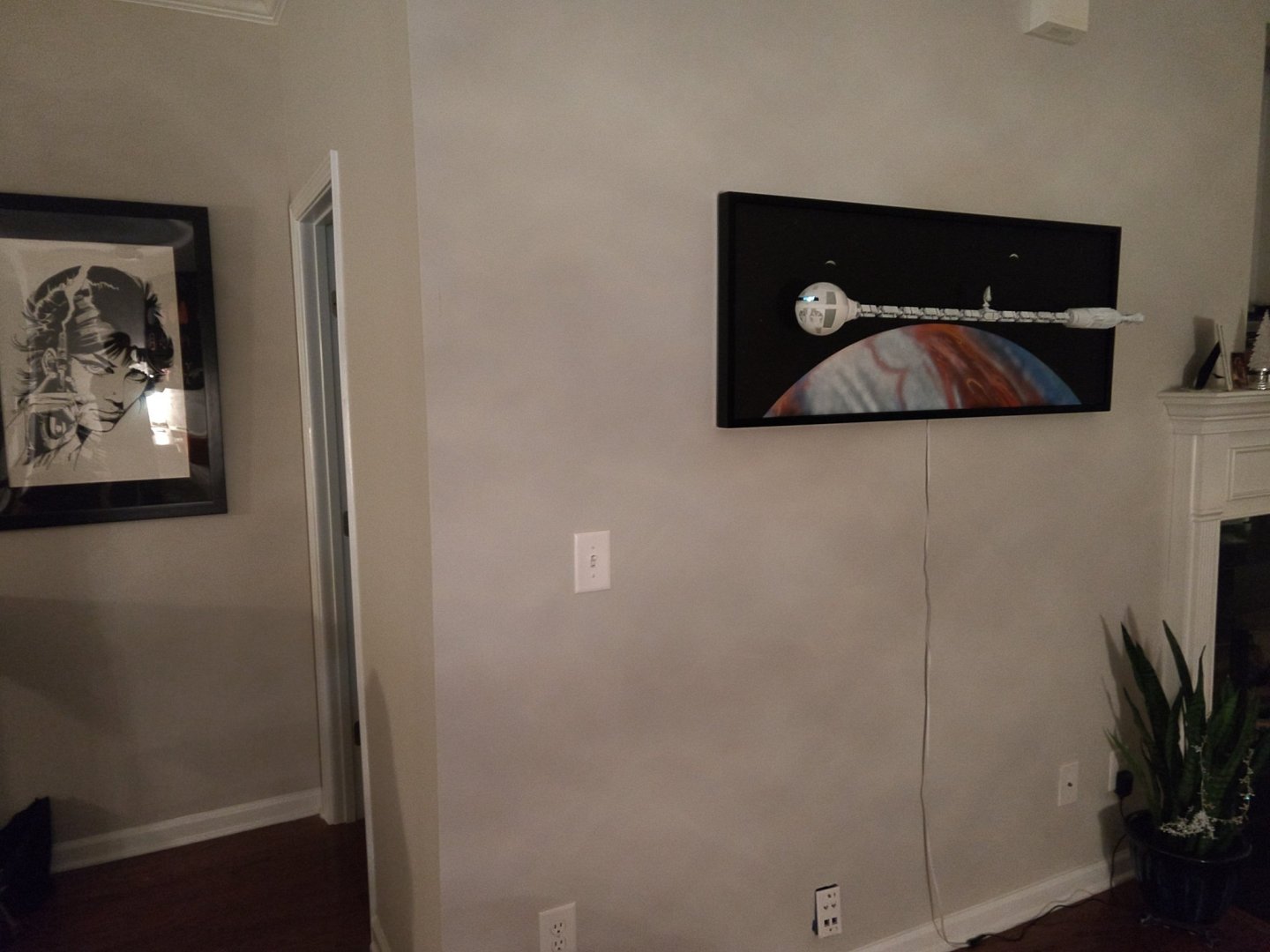
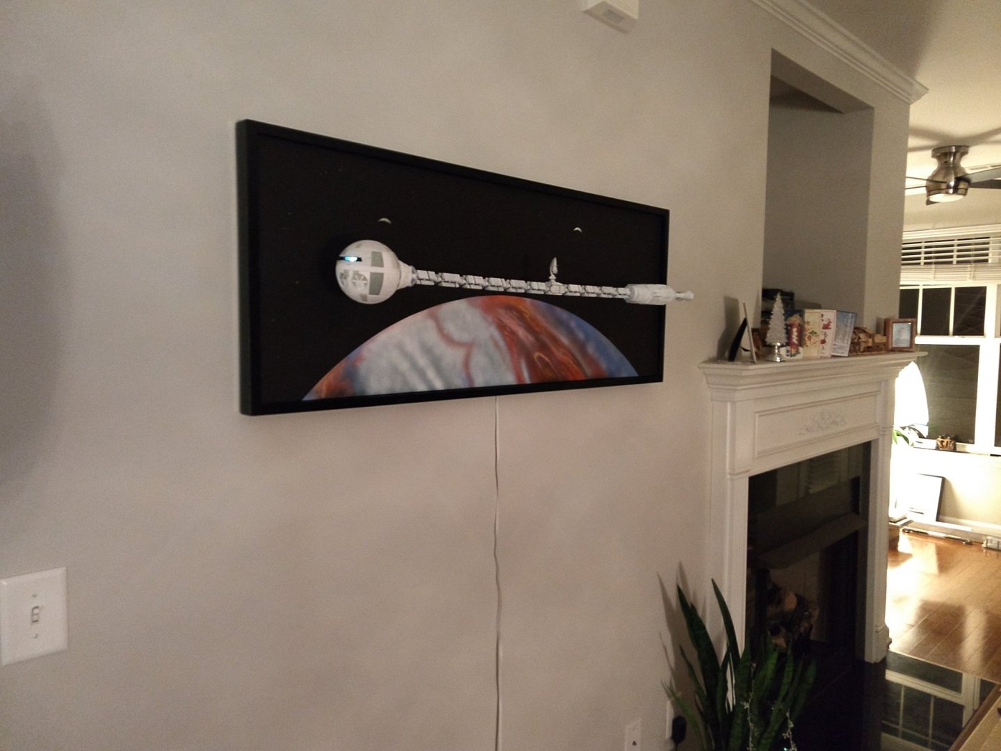
And we finally come to an end of this project. Discovery is now orbiting the giant Planet Jupiter I hope you have enjoyed that project. Yves


- 119 replies
-
- 24
-
-
Superb work of patience and Love. Yves
-
This Spanish Economic Web site seems to imply that AL is "In liquidacion", meaning Chapter 11 in the USA, or "toasted" for the rest of the world: https://empresite.eleconomista.es/ARTESANIA-LATINA.html Yves
-
Re.... Hmmmmmm Why would a Spanish company go to HongKong? So unstable and so far away from their normal territories. Maybe the wife convinced him.... That could be a disastrous situation. Maybe the "Son" does not care.... Yves
-
Beautiful results on the planking and nailing. Yves
-
YTL-45 Taiwanese Navy tugboat by Erik W - FINISHED - 1/350 scale
yvesvidal replied to Erik W's topic in Plastic model kits
Absolutely superb. You should move that thread to the Build Log area. Yves -
oh oh somebody is smuggling liquors in the bilge.... Yves
- 90 replies
-
- 3
-
-
- billing boats
- colin archer
- (and 1 more)
-
Beautiful and so peaceful. What a great cloister. Yves
-
Coming along nicely. You are making great strides with this diorama. Yves
-
Great project Nils. When I was a kid, I was drooling on the Hjejlen kit in the Toulouse Hobby Shop (Ideal Models). I never got it but I always kept it dear in my heart. I am so glad you managed to find such a beautiful model and give it a second life. Yves
- 38 replies
-
- 4
-
-
- billing boats
- hjejlen
- (and 2 more)
-
Beautiful paint.
-
Amazing. Thank you for the very detailed explanations on how you proceed to build the deck. Yves
-
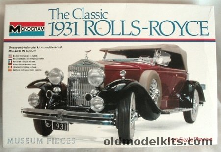
I stand corrected: monogram only produced the Roadster model: Your kit was distributed by Testors and Italeri. Yves
-
Very nice subject. Are these a re-edition of the old Monogram Kits? I built quite a few of the old 1/24 Monogram kits but cannot recall this one in particular. Once you have done this kit as an appetizer, you can try tackling the Pocher kit at 1/8th scale..... Very expensive though.... Yves
-
I love all Venetian vessels of all kinds....but my favorite remains the Vaporetto shown on the picture. What a beautiful model!!! Yves
-
Yes Clare, a beautiful kit for that POD at 1/8 scale. I think Dubz (Dirk) has bought that kit but I am not sure if he will start it soon and describe his build. Yves
-
Clare, you are absolutely correct. Of course, it is not the module that triggered the neurosis crisis within HAL9000, but the prospect of loosing its individuality and intelligence, after reading the lips of the two astronauts. The second replacement of the module was just an excuse to terminate one of the crew, after taking care of the three scientist in hibernation. Thank you for your enthusiasm and please show us what you will be building on the subject of 2001. Yves
-
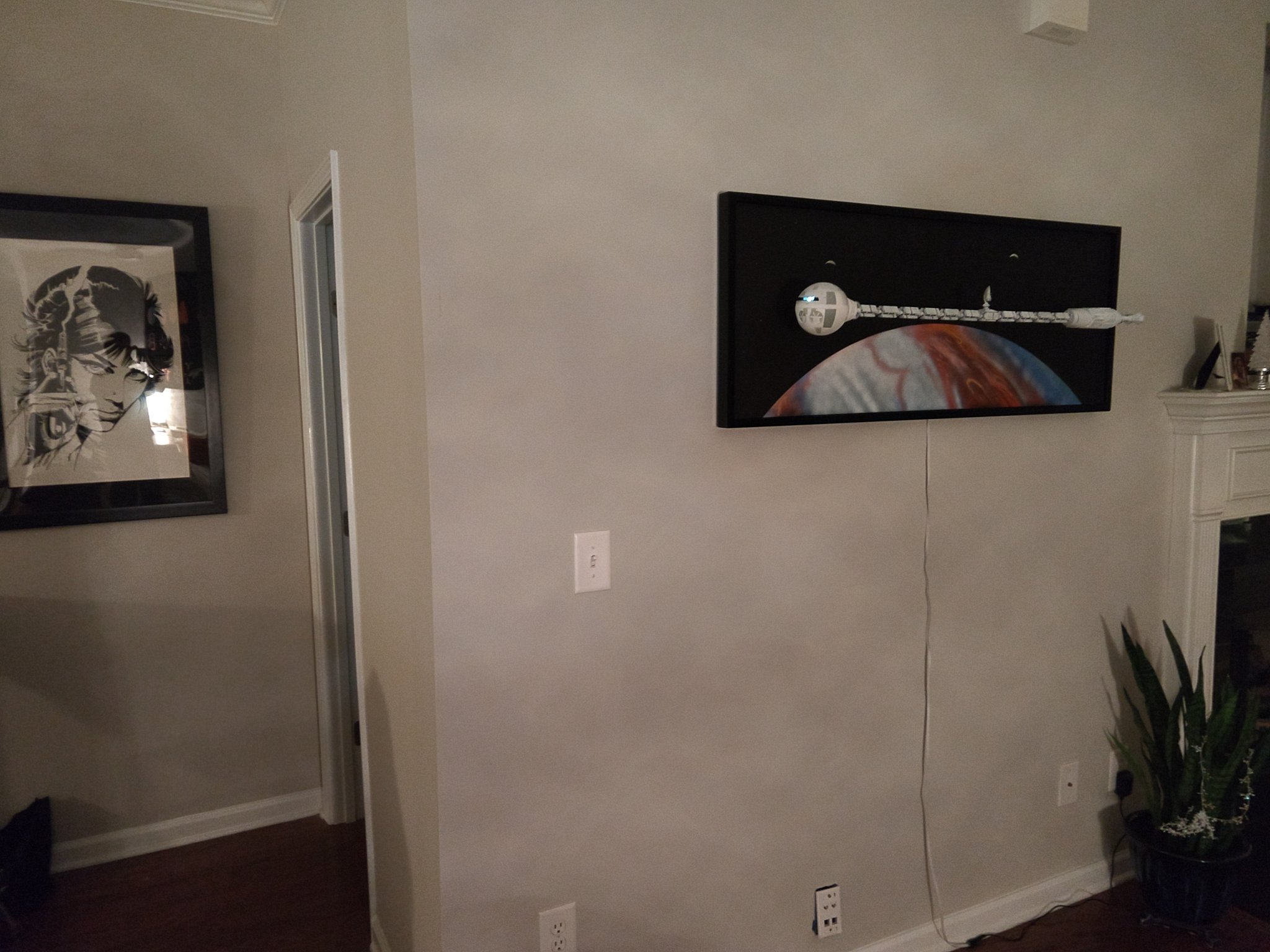
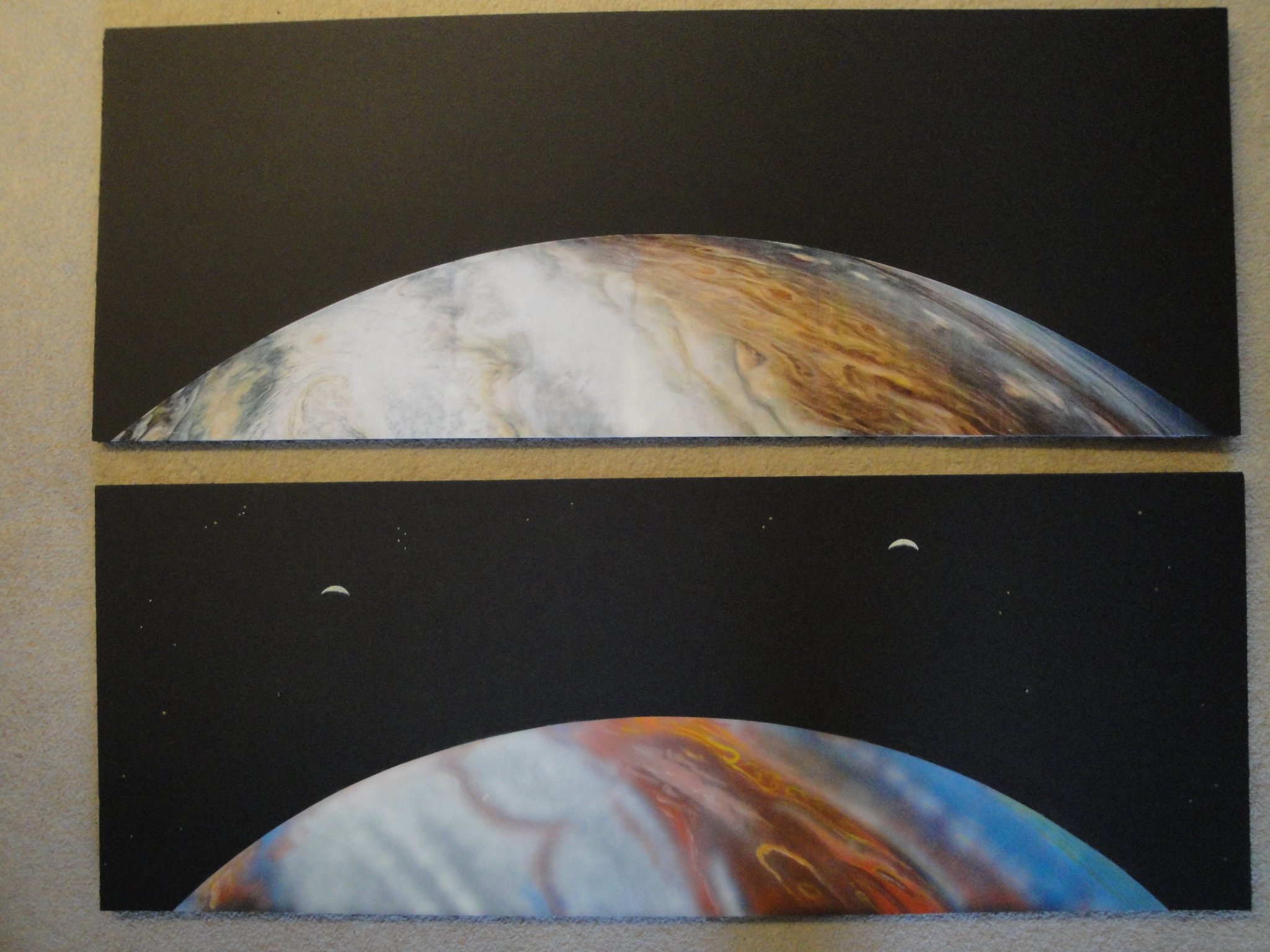
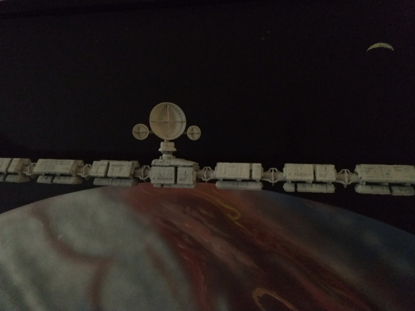
I hear you Hubert, and of course, there is no way my poor painting skills can compete with a picture from NASA. However, the seams between the sheets are not giving me complete satisfaction and I have tried to improve on my painting a little bit. Jupiter is not an easy planet to depict due to the variety of colors and the tumultuous atmosphere. Here is where we stand right now. I have also included a couple of moons partially hidden from the sun by the enormous planet in front of them: Yves

- 119 replies
-
- 12
-
-
It is a great idea to plank this plastic model. You will not regret it. Yves
-
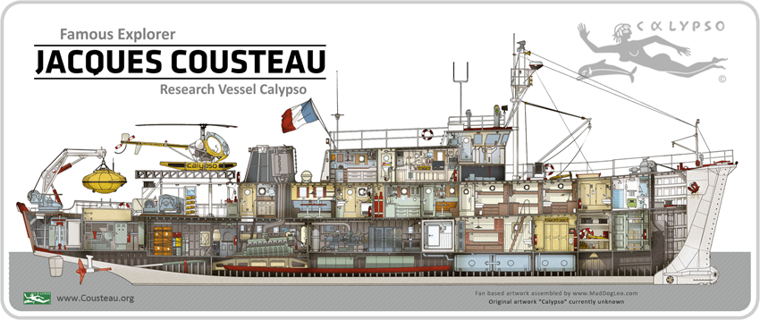
A nice drawing of the vessel interior: Yves