HOLIDAY DONATION DRIVE - SUPPORT MSW - DO YOUR PART TO KEEP THIS GREAT FORUM GOING! (83 donations so far out of 49,000 members - C'mon guys!)
×


yvesvidal
-
Posts
3,607 -
Joined
-
Last visited
Content Type
Profiles
Forums
Gallery
Events
Everything posted by yvesvidal
-
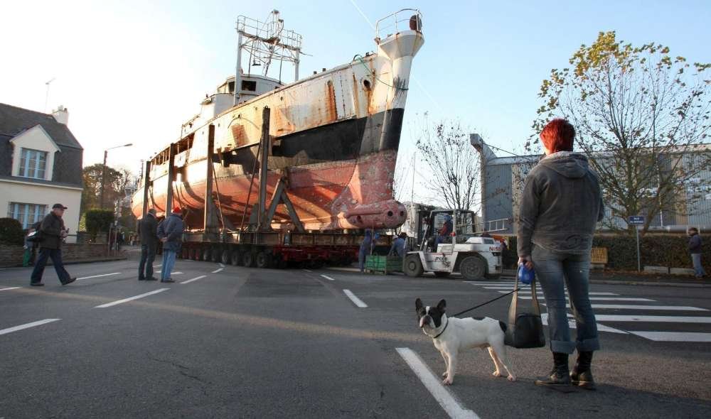
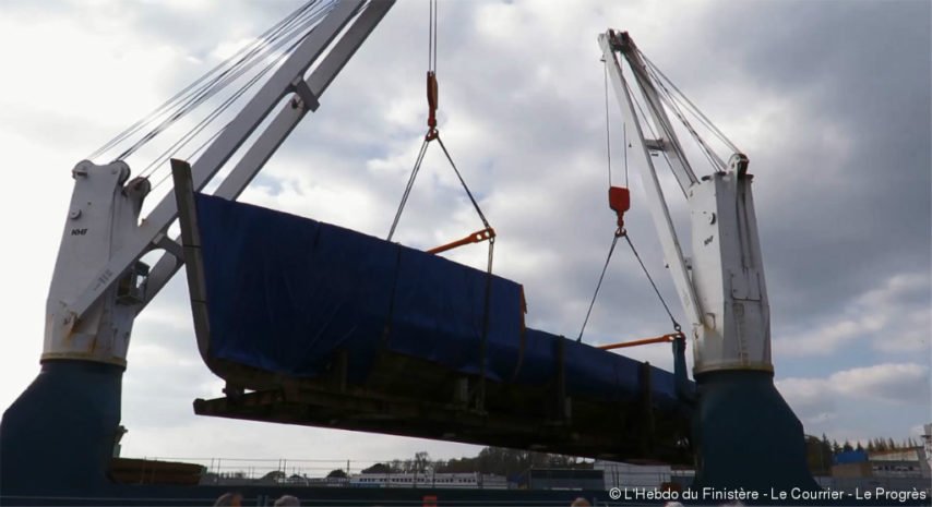
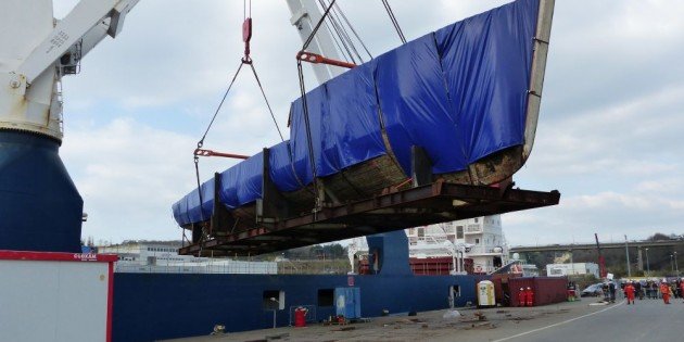
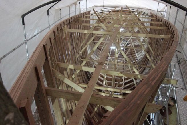
 Sorry Luekutus, I am not trying to hijack your thread but found these interesting pictures of our beloved boat on the French sites. Arrival in the Harbor of Concarneau in France: Calypso in her way out of Concarneau, after the beginning of the restoration. En route to Turkey..... Arrival in Turkey: Renovation in Turkey: More details in French: https://www.bateaux.com/article/25424/renovation-de-calypso-un-chantier-avance YvesLa Calypso arrive en Turquie _ Mer et Marine.html
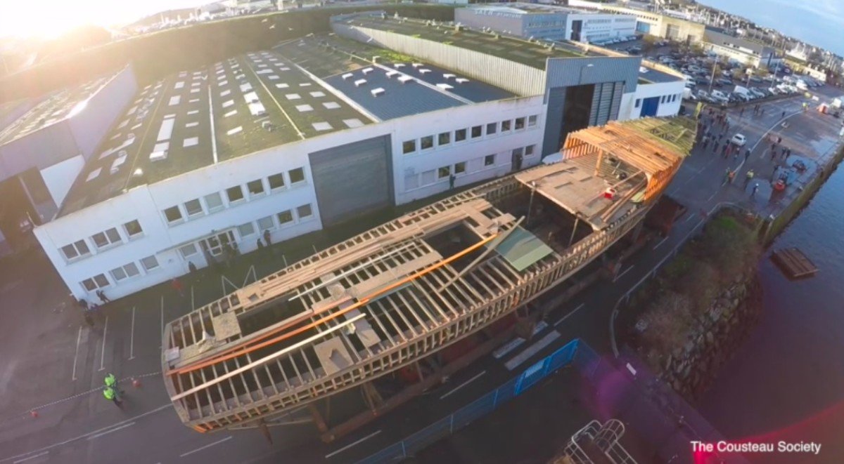
-
I remember the Hjejlen Kit from when I was a kid..... Long time ago. What a beautiful model that you realized. Yves
-
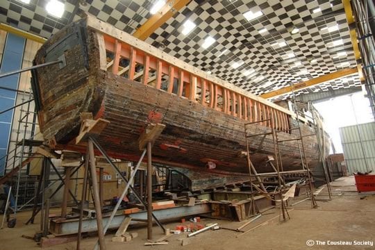
It is not easy to see, but the planks were actually nailed with metal rivets: Those rivets may have been made of aluminum to cancel all magnetic properties. Difficult to say. Interestingly enough, Calypso was supposed to be restored in Concarneau (France) and the picture above shows the very slow work that took place. The French government and the Cousteau Foundation started arguing and the ship has been basically rotting almost untouched until 2016. At that point, Calypso was moved to Turkey where the Foundation found a shipyard willing to restore the vessel. Apparently, the French Government refused to sponsor the reconstruction of Calypso, even though the ship has been attributed the title of Monument du Patrimoine National as is the Cathedral of Notre Dame and the Eiffel Tower. Recently, the Turkish naval shipyard was making good progress when a fire caught up and destroyed all the newly restored section..... Tough luck for that poor vessel. The Cousteau Foundation is not giving up and has decided to continue the restoration. You can read more details in the French Trade press. Yves
-
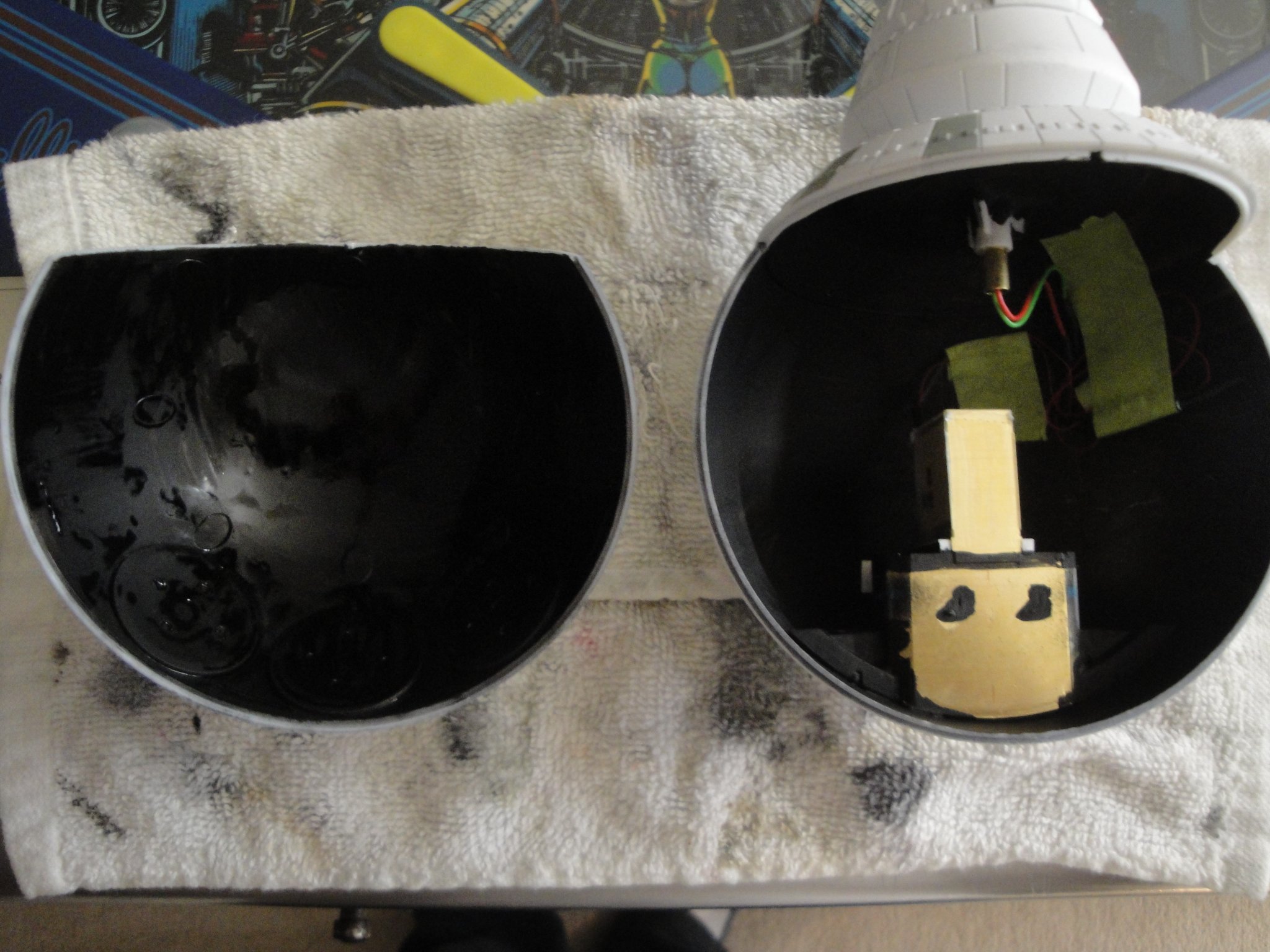
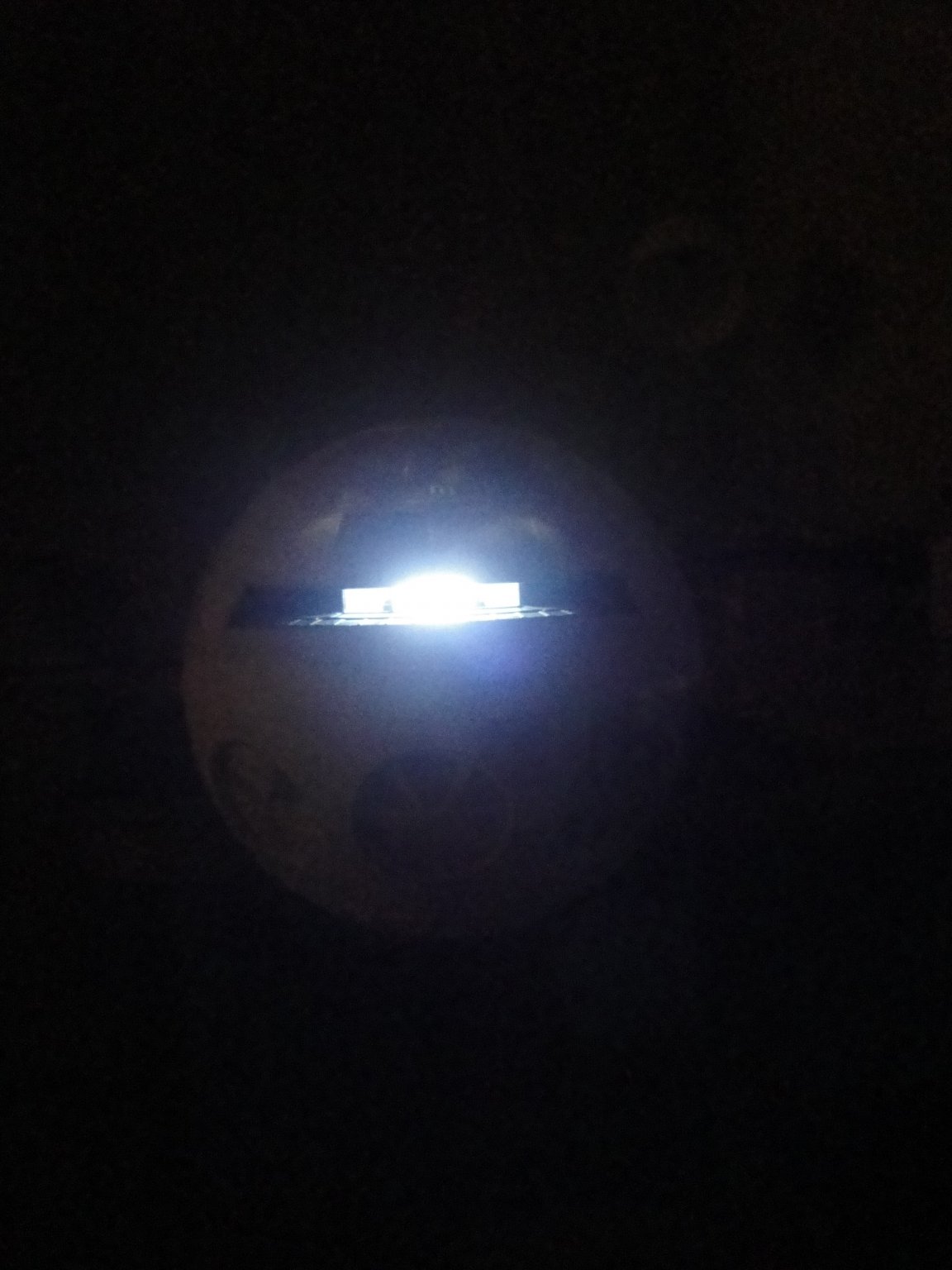
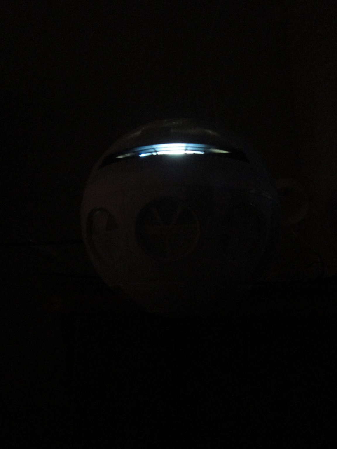
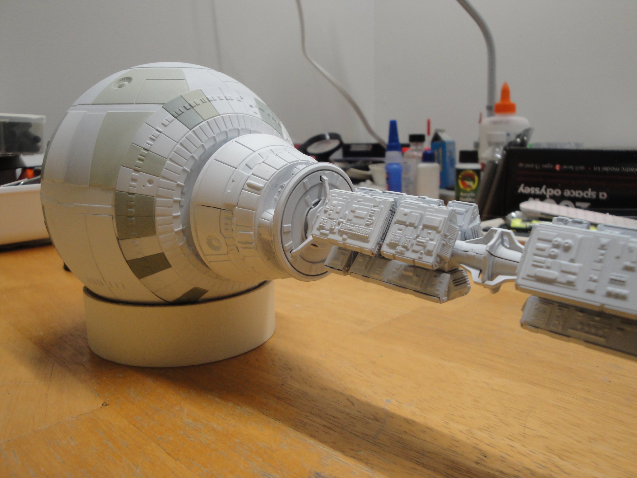
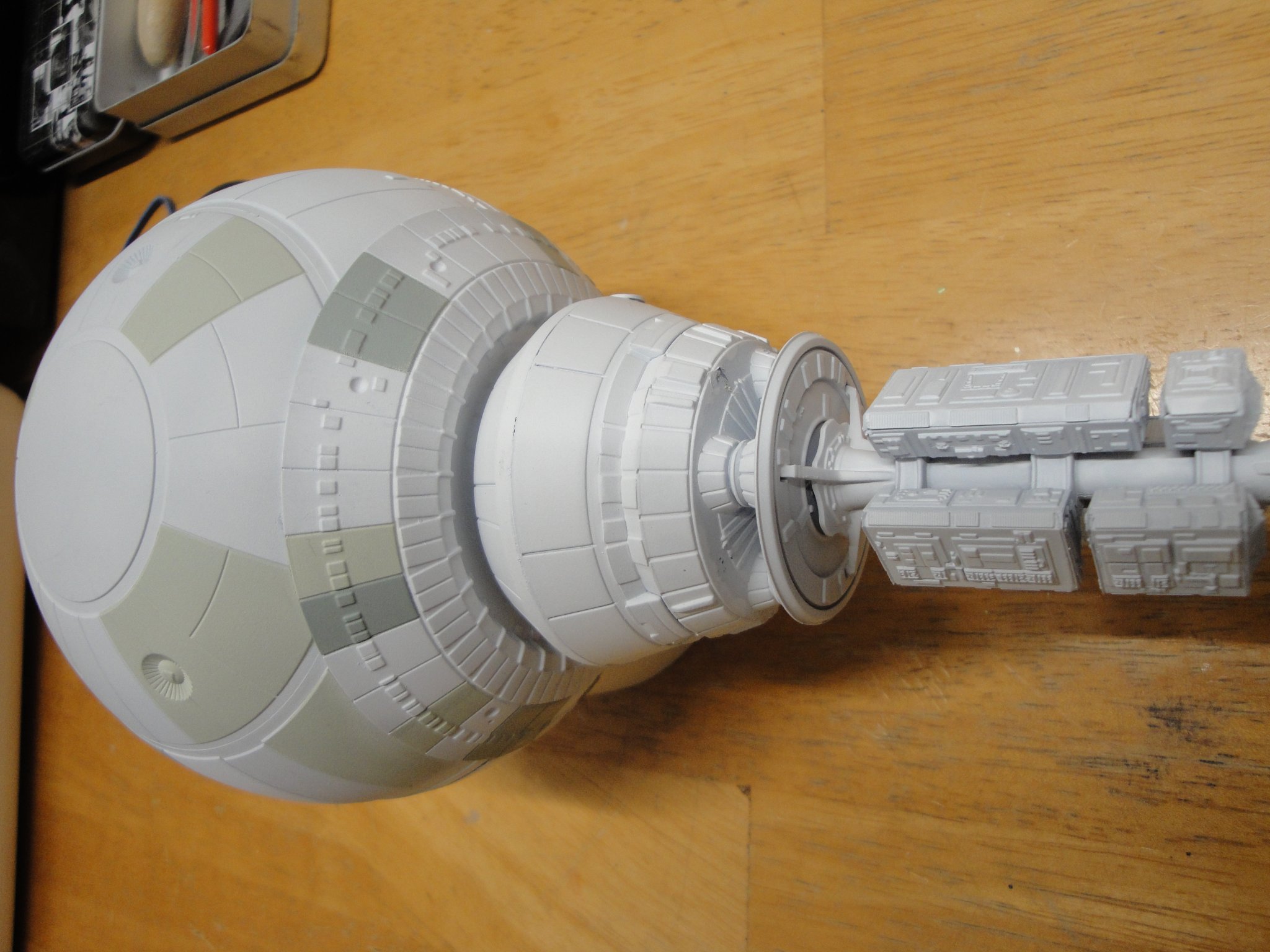
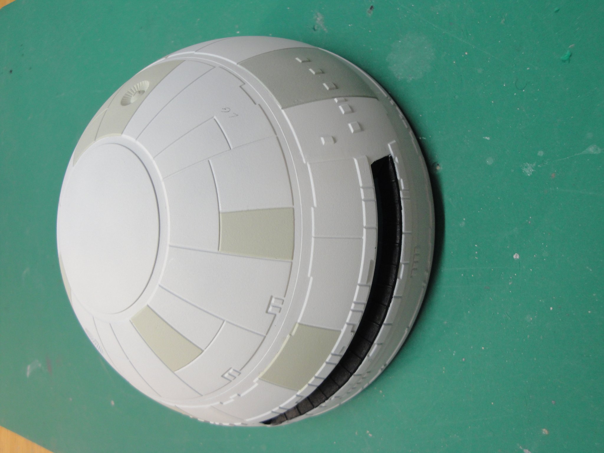
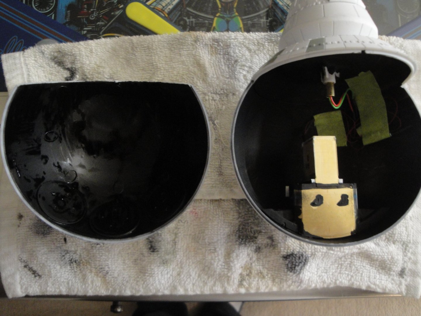
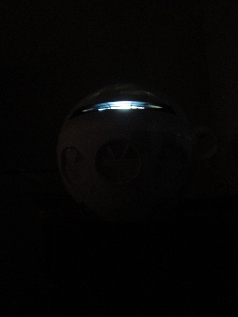
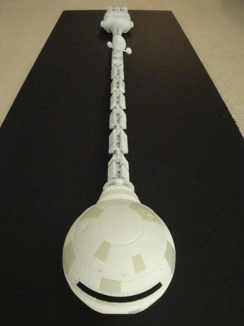
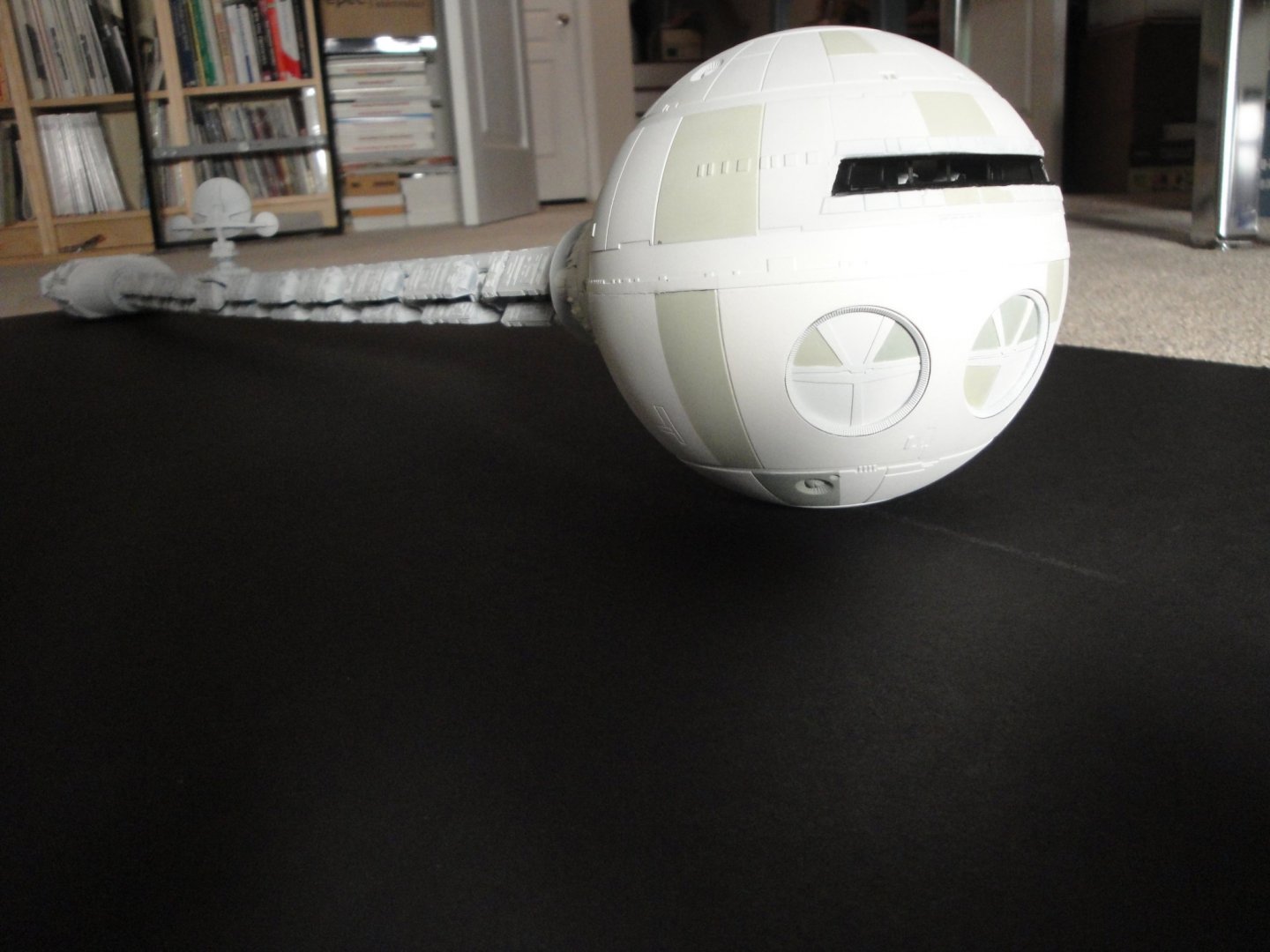
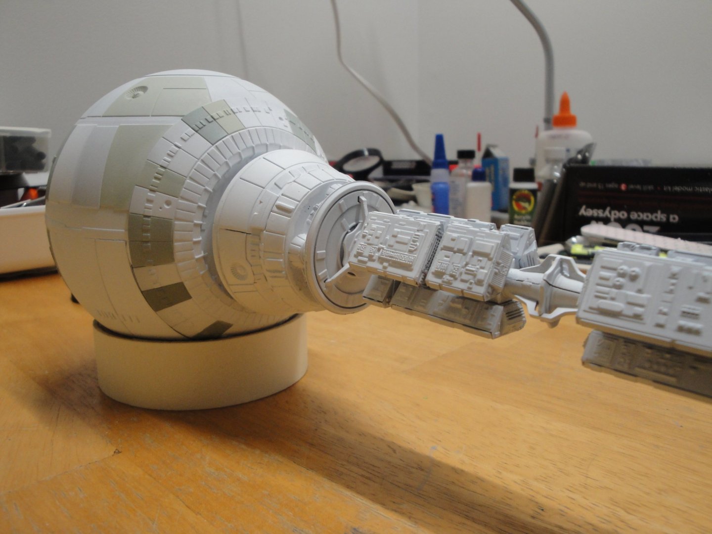
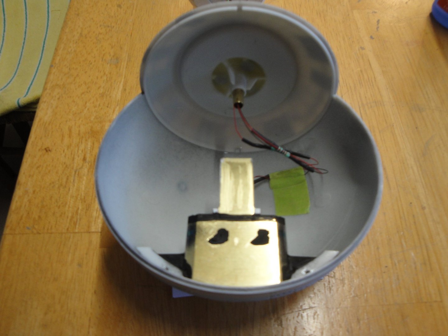
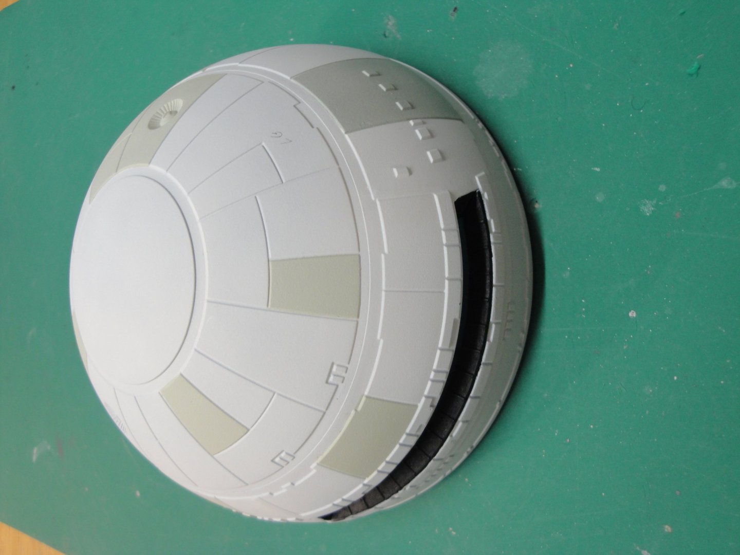
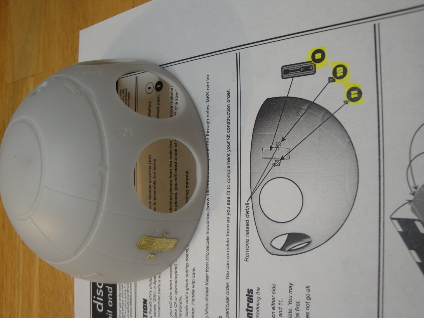
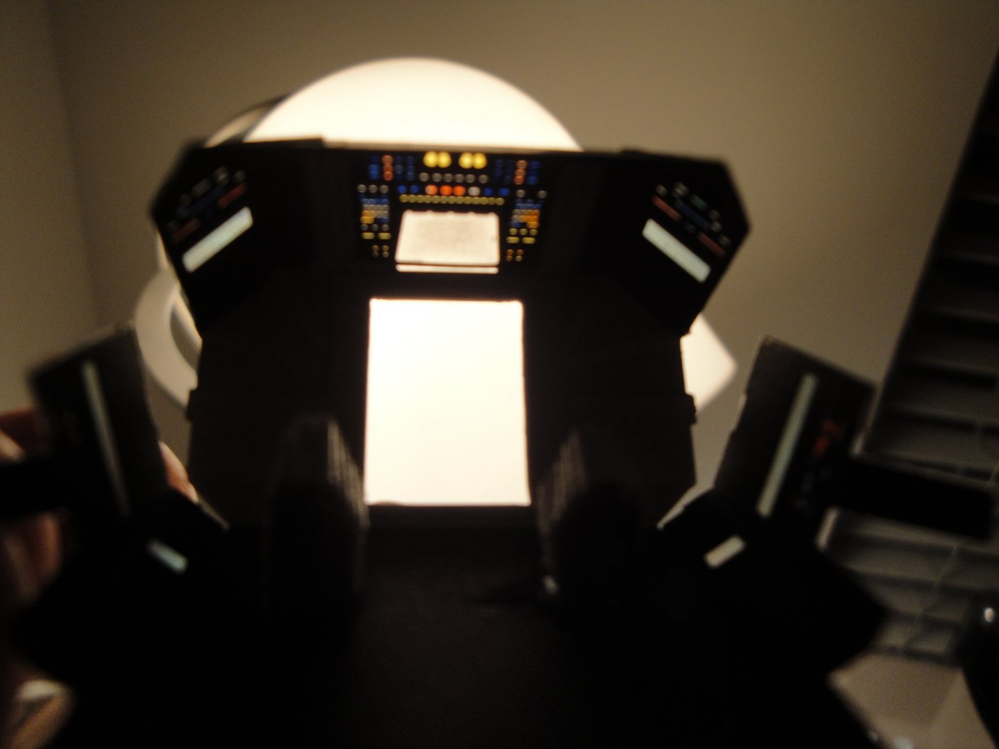
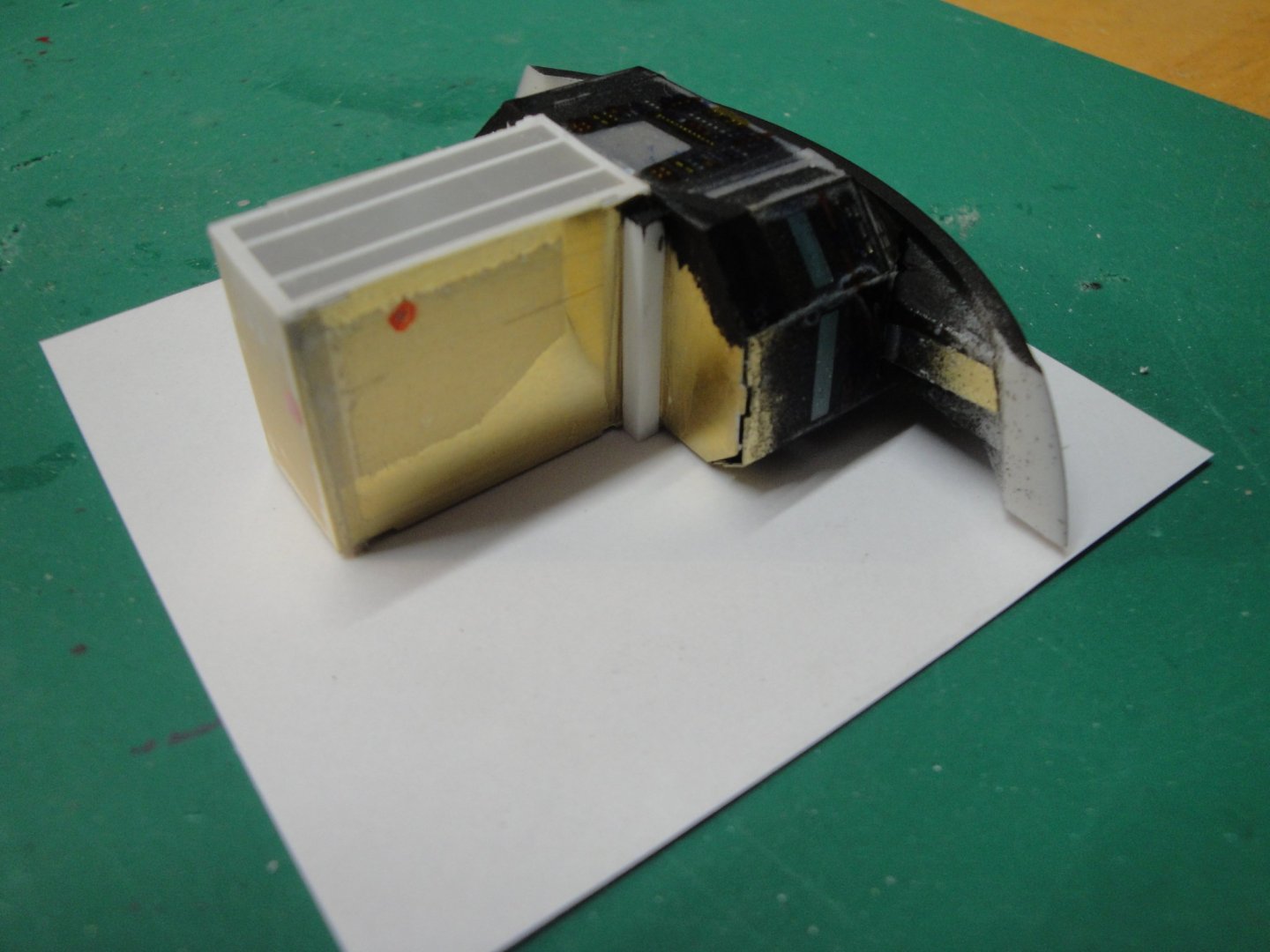
I am almost done with the vessel. There will be some pictures and some comments I would like to do about the kit and how I approached it. Hopefully, my mistakes can help other modelers to not fall in the same pitfalls. Before closing the sphere, it is recommended to paint the inside black or some opaque color. Let's remember that the sphere itself is used as a light chamber and as such, the white LEDs are blasting totally uncontrolled: First mistake (now too late to correct it: I painted using a brush, as I did not want to spray black all over the white external paint. That is not good enough. You need to spray (air brush) to really get something opaque and to prevent the light from seeping out. I have the black coat, the white plastic, the German grey coat and multiple coats of mat white. You will not believe it, but the light managed to seep through in a couple of tiny places. It can only be seen in complete darkness and not in moderate low light. The brush stroke are not as thorough as the airbrush and in retrospect, spraying inside with German Gray would have been better than brushing black mat paint. Below are a few pictures taken in full obscurity. On the right seam joining the two halves, you can distinguish a small light leak.... Some leaks also above the windshield. I probably will end up reducing the voltage of the LEDs, to tone them down a little. The entire vessel is now completed. It is quite difficult to picture it, due to its length. Doors are hand painted with a white background airbrushed. Second big mistake I did (and this because of the light circuitry in the sphere) is to close the two halves of the sphere AFTER painting. Big mistake. The reason is the two halves are not matching exactly and because of the rear bulkhead already glued, the lower half was protruding a little bit, forward. So, I sanded a little bit the rear part of the lower half to make it fit better in the front. In addition and that is the big problem, when gluing the two halves, I ended up damaging the white paint on the seams. I had to delicately sand (without butchering the painted panels), mask again and do some touch-ups with my airbrush. Not a pleasant job and rather nerve wracking. So, if you decide to build that model, follow the instructions, glue the two halves together, spray the inside opaque, do all the interior details that you want to add, glue the rear bulkhead and paint the whole sphere separately from the rest of the vessel (white plus panels masking). Think how you are going to connect your electrical wires ahead of times..... There is not much room and the steel rod does not give you a lot of latitude to play. Anyway, you can see on the next two pictures, the coupling of the two halves and the rear bulkhead. It is not too bad, but it could have been better. I am working at filing up the triangular gap and paint it carefully. Overall, it is a great kit with parts joining neatly and cleanly. The two halves are a little bit delicate to glue together and a few modelers have been complaining about them in other forums. In retrospect I did not have much of a choice but I should have handled the painting of the sphere as one block. What remains is to finish the background painting, and install the power supply on the frame. Stay tuned... Yves Yves


- 119 replies
-
- 16
-

-
You should negotiate a contract with Model Shipways to provide them with high-quality parts for some of their kits. Yves
- 222 replies
-
- 1
-
-
- sultana
- model shipways
- (and 1 more)
-
There was one at the past 2019 Oshkosh air show. A real monster when you stand next to it. Unfortunately, I did not take any picture. I also had the chance to work while in France (IBM France) with one of the 12 French pilots that were trained on these machines by the US Air Force. The lad had some salty stories about the Avenger.... Yves
-
Interesting to see that modern technology on such an old vessel. What a contrast. Yves
- 222 replies
-
- 1
-
-
- sultana
- model shipways
- (and 1 more)
-
Absolutely stunning. Beautiful model and great paint job. I love the deck with the various shades of wood. The hull is beautiful because you can see most of the planks. It adds to the realism of the model. Will you be drilling the hull with 256 holes for the well? Yves
-
Really cute and sweet. Yves
-
Try E-Bay (European sites ebay.fr, ebay.gr, ebay.it where these kits were sold) and Facebook Marketplace. With Patience, you may get the missing issues. At worst, you will have to fabricate the missing parts. Good luck. Yves
- 1 reply
-
- 1
-
-
Echo by davec - FINISHED - cross-section
yvesvidal replied to davec's topic in - Build logs for subjects built 1751 - 1800
Chuck, I hope it will motivate you to resurrect the Cross-Section kit that you had in the back of your mind, at one time. Yves -
I wish I could hire you to weather my Submarine.... Fantastic job on the Essex and what a collection. Yves
-
Superb work. Yves
-
I am very happy that you are starting (actually resurrecting) this build, of such an iconic ship. I built the Billing Boat kit quite a few years ago, with my first paycheck from IBM, when I was still on the French Riviera. I built it for RC and my model has sailed on the sea (Cagnes Sur Mer harbor) and many lakes, including Boston, MA and Raleigh, NC. I have been thinking about renovating it, but have been derailed by many other projects. I never thought about planking the ABS hull, but you have a fantastic idea, there. Below is the presentation of my model, not a Build log as you will (hopefully) present us: Looking forward to seeing your progress. Yves
-
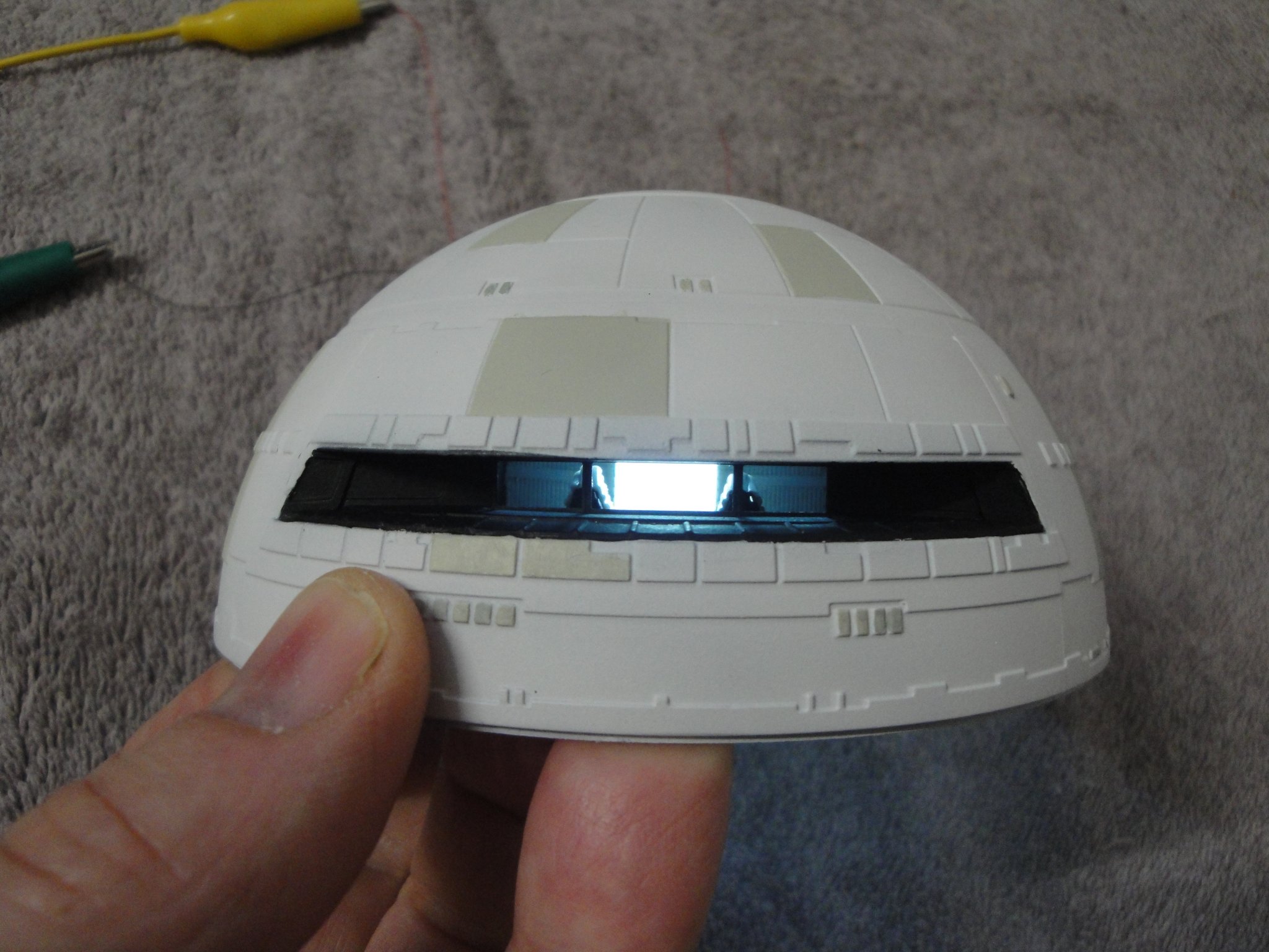
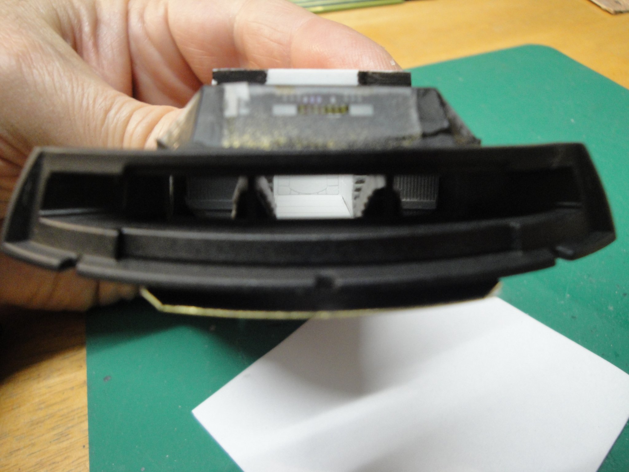
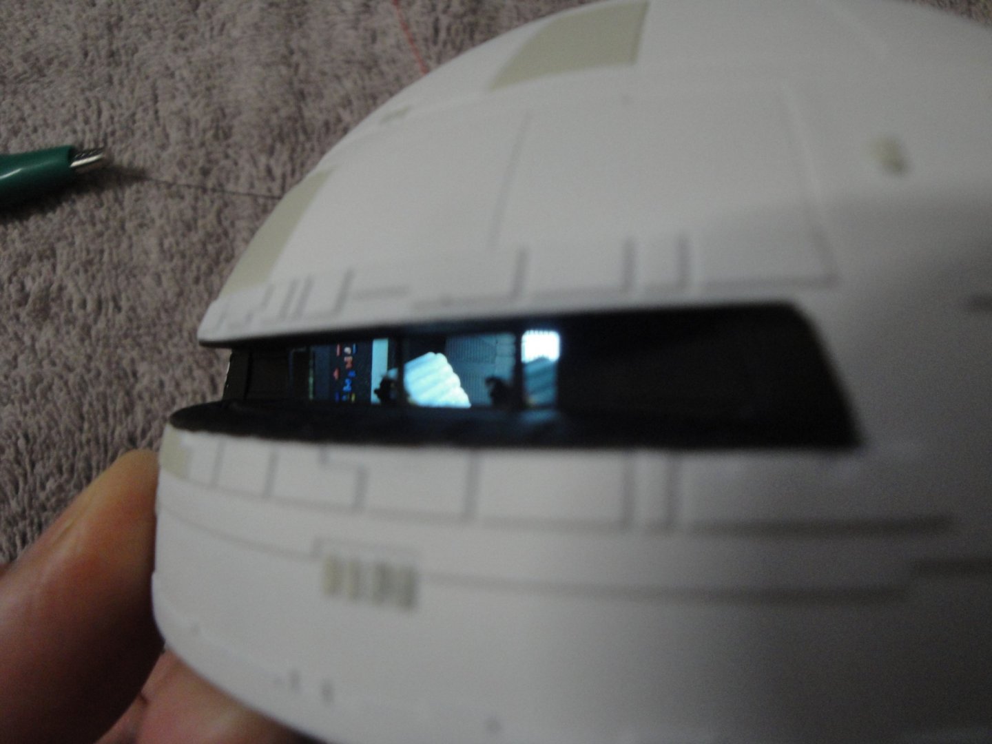
Yes, it is a camera/picture issue. When you look at it, it actually is not so bright and you can see some of the controls. It is just that the control lights are so recessed that it is almost impossible to see them. Yves
-
You are doing a very fine job. It is superb and very clean. I love the meshing.... Yves
- 171 replies
-
- 1
-
-
- artesania latina
- bounty
- (and 1 more)
-
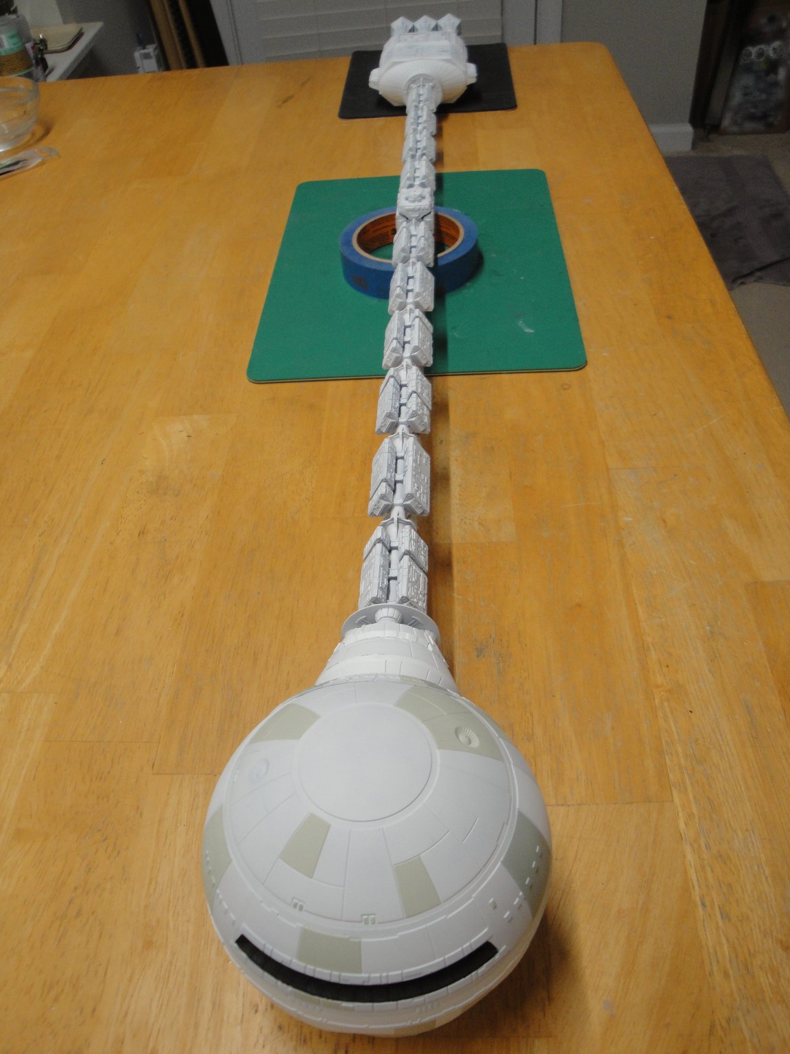
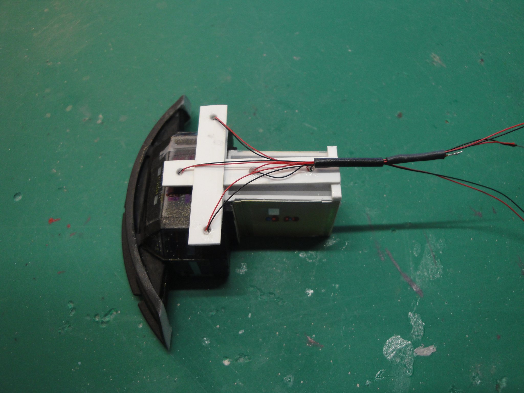
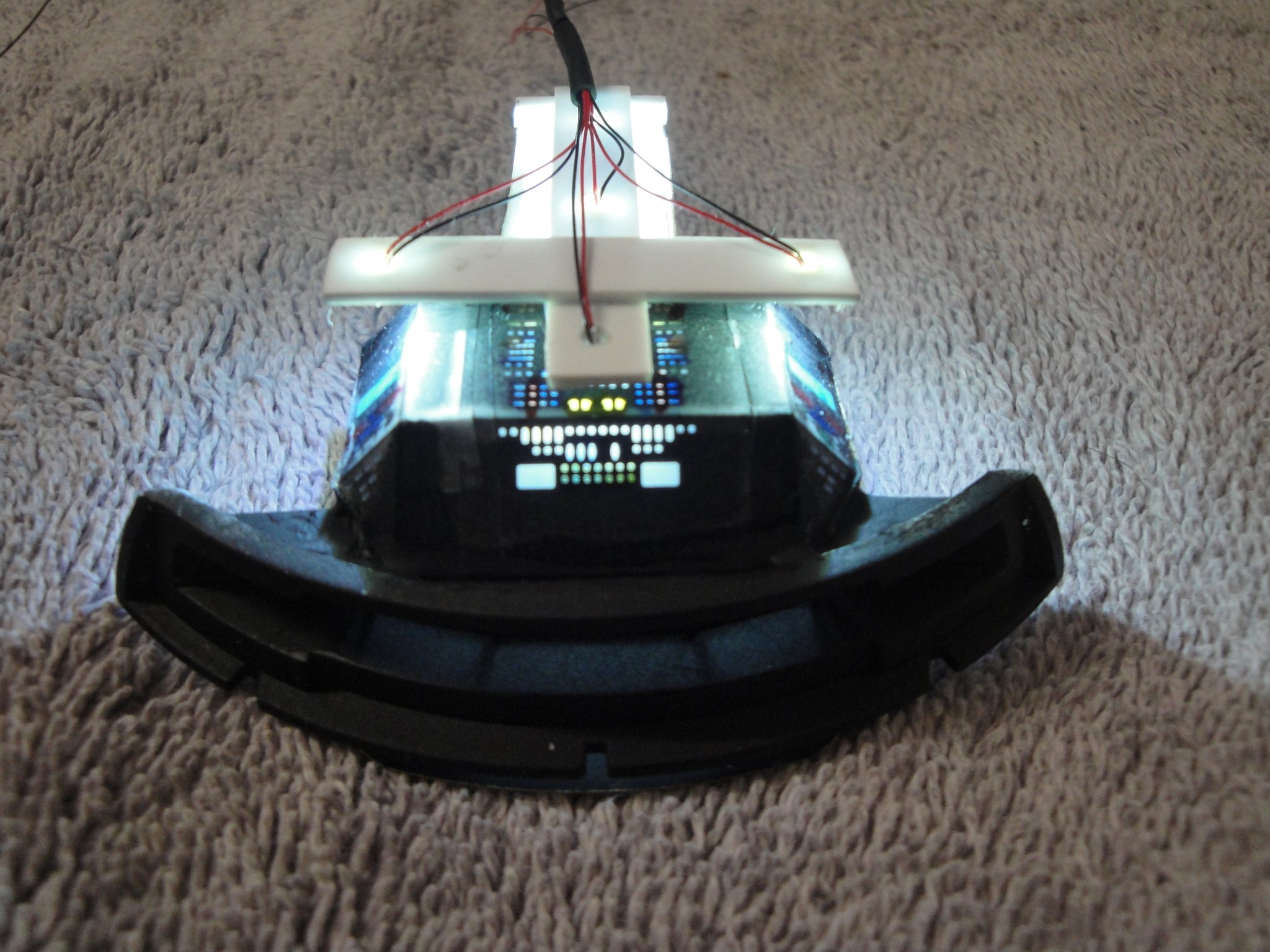
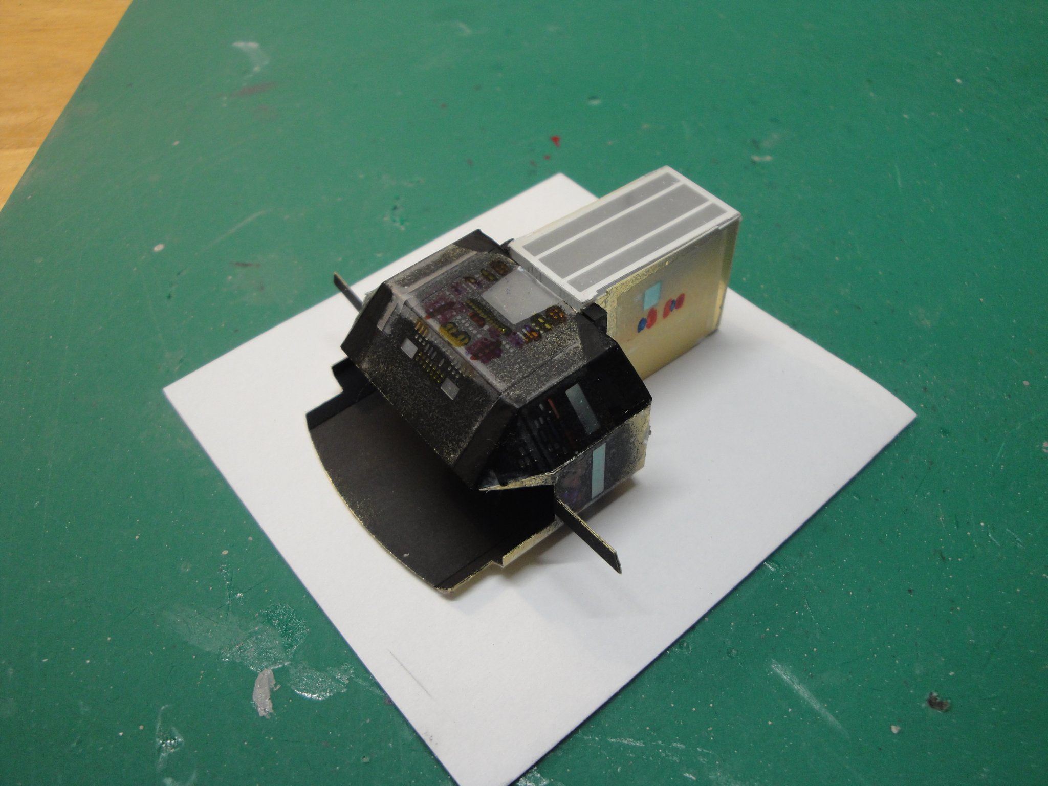
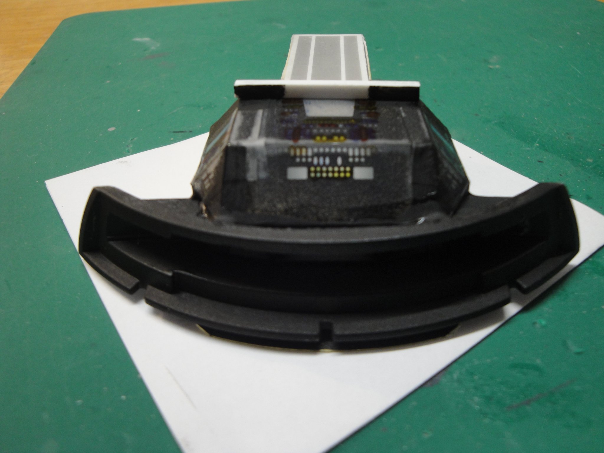
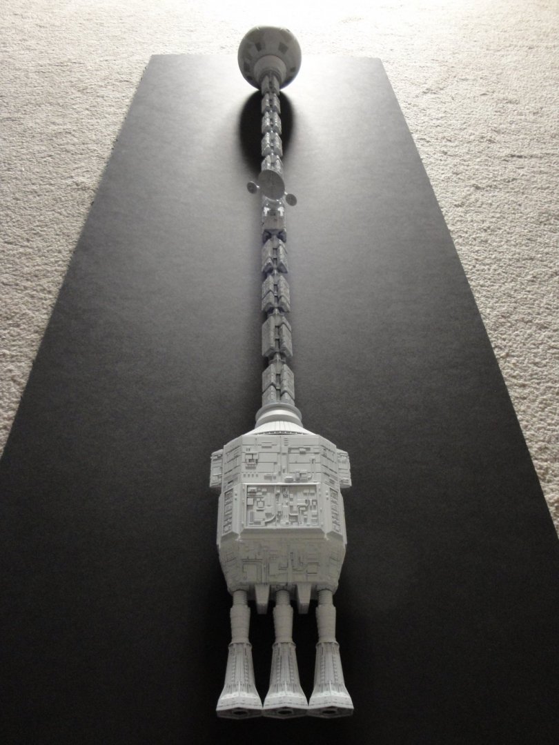
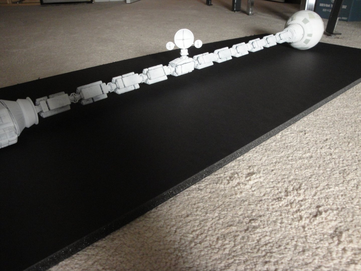
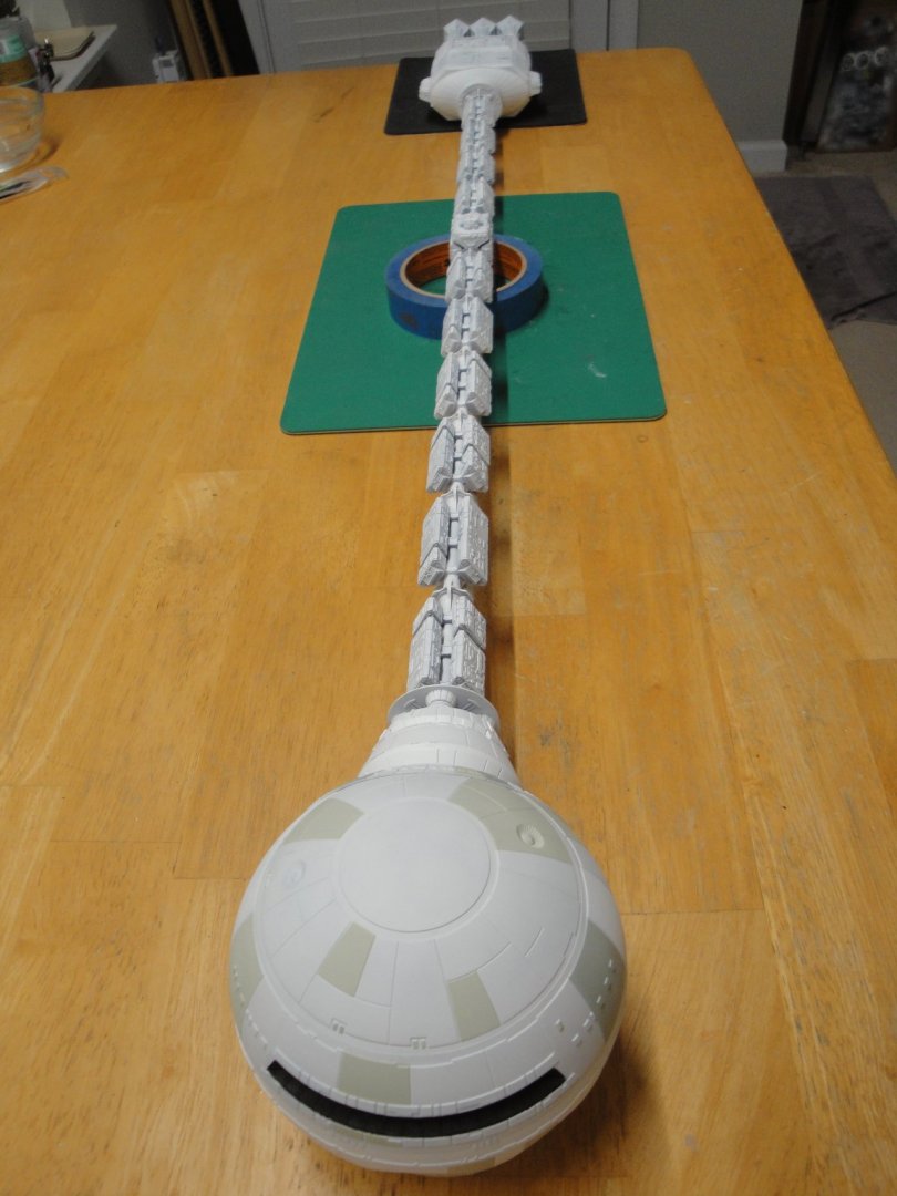
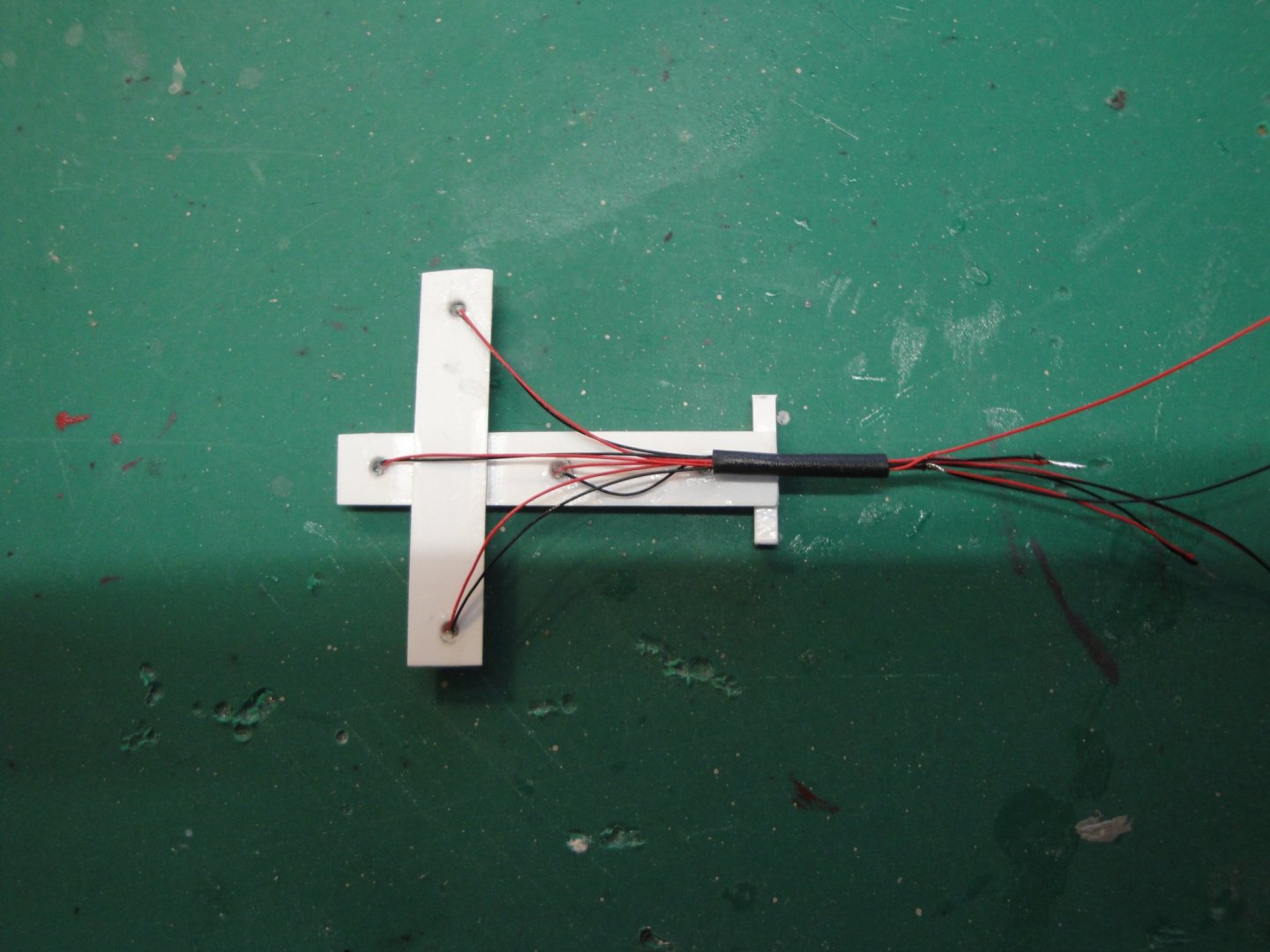
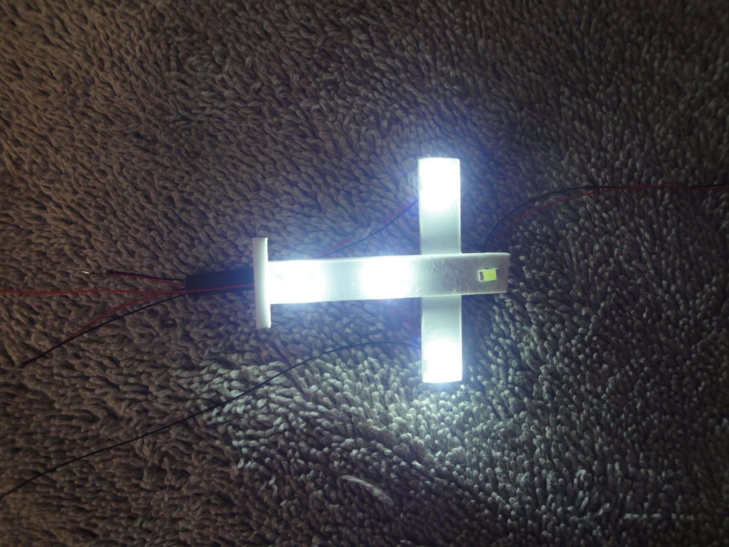
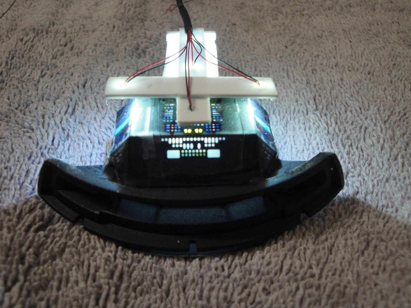
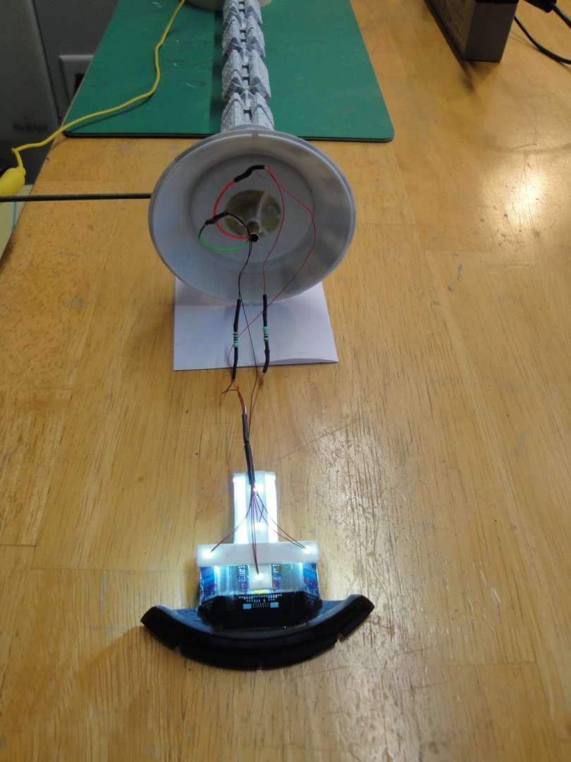
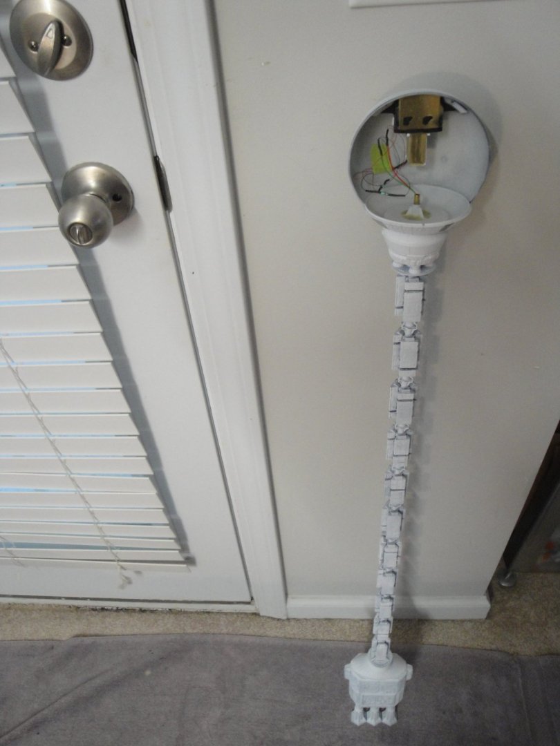
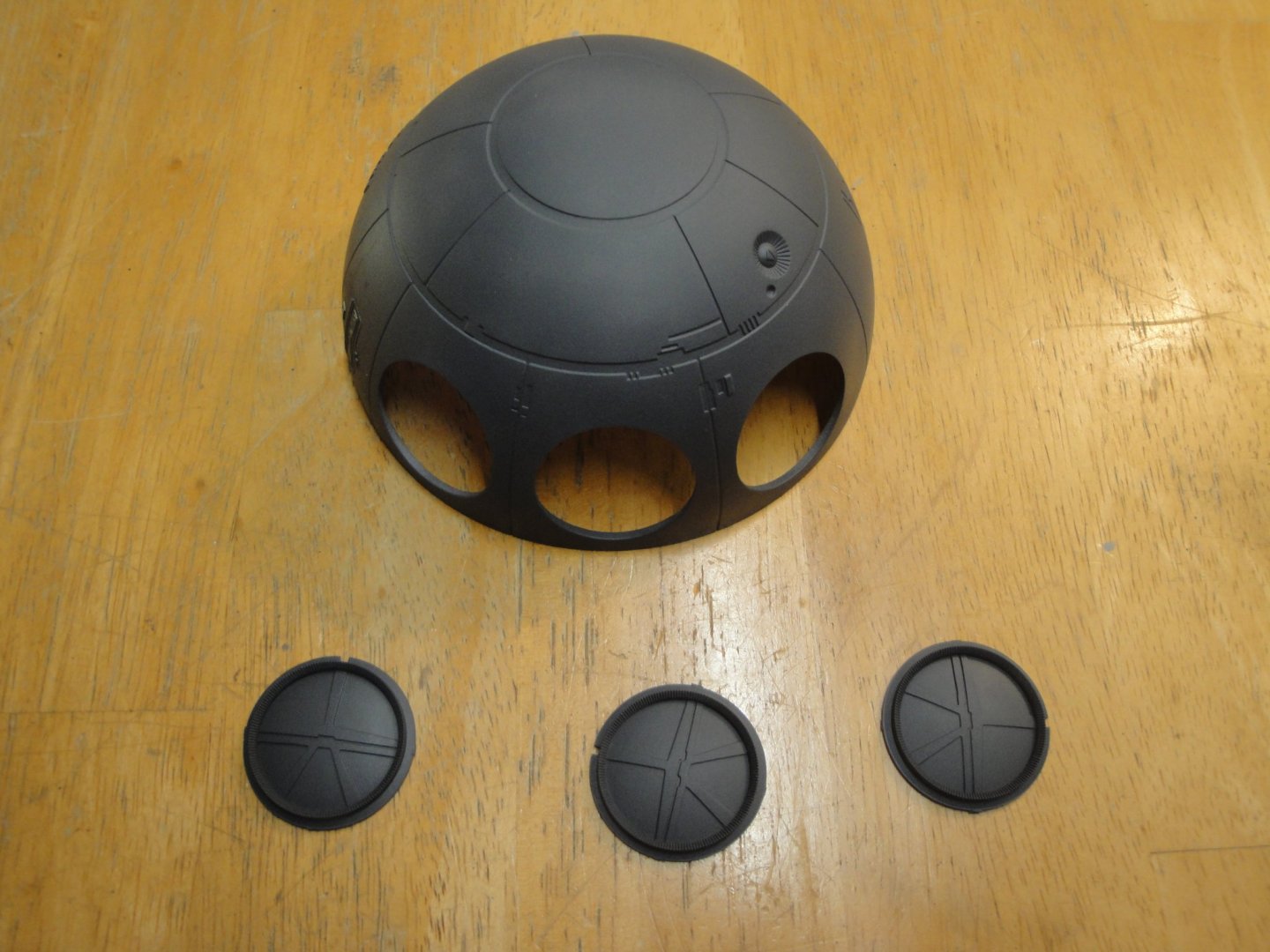
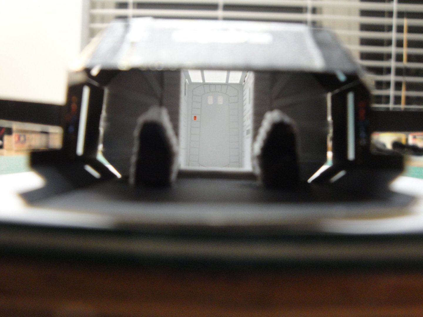
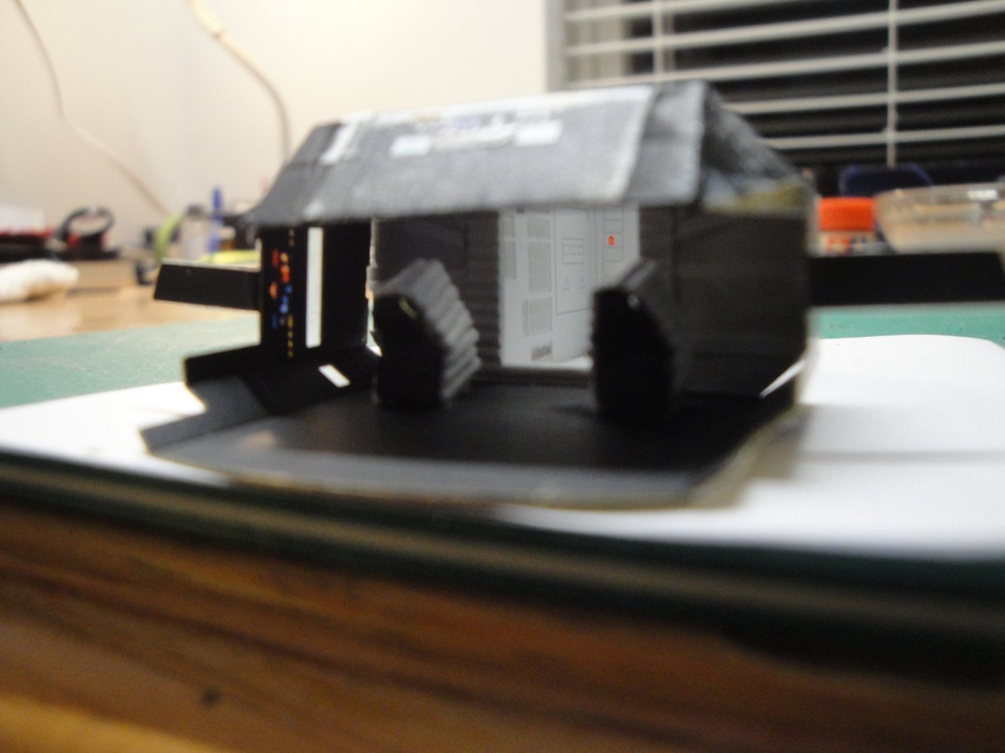
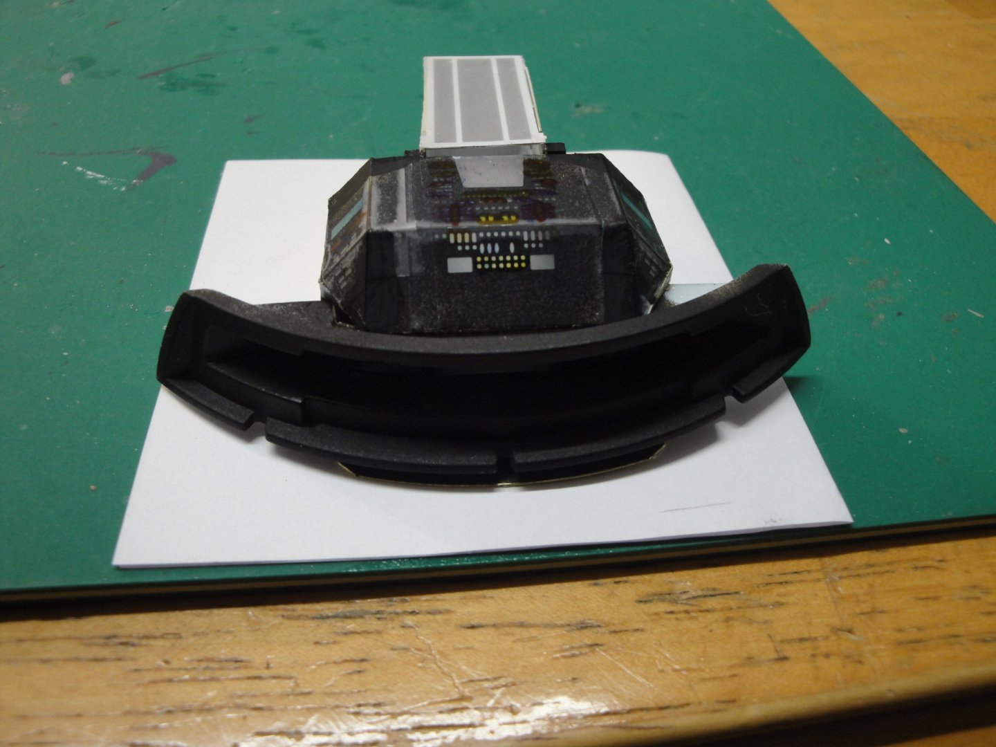
Moving along with no coming back..... I created a little cross of styrene, with 5 micro-LEDs: The fifth LED is not yet connected: We now mount the cross on top of the cockpit deck: Our first trial: from the outside, it looks good....but the inside remains kind of a mystery as the window is so small: You can see some of the control panels below: Trying different angles.... yes, twisting your neck you can see some of the controls..... The electrical connections to the main bus are done. There is enough slack in the wires to remove the sphere: It is now time to glue the cockpit deck inside the upper half, and to glue the upper half to the rear bulkhead. The rear bulkhead (and the sphere..) holds by a very tight coupling (that brass tube over the spine) and three strong magnets. The three small prongs of the kit are helping too. We will not loose the living spaces on our way to Jupiter: Quite a tall model..... Yves


- 119 replies
-
- 18
-
-
This is turning into a plastic model..... :-) Yves
-
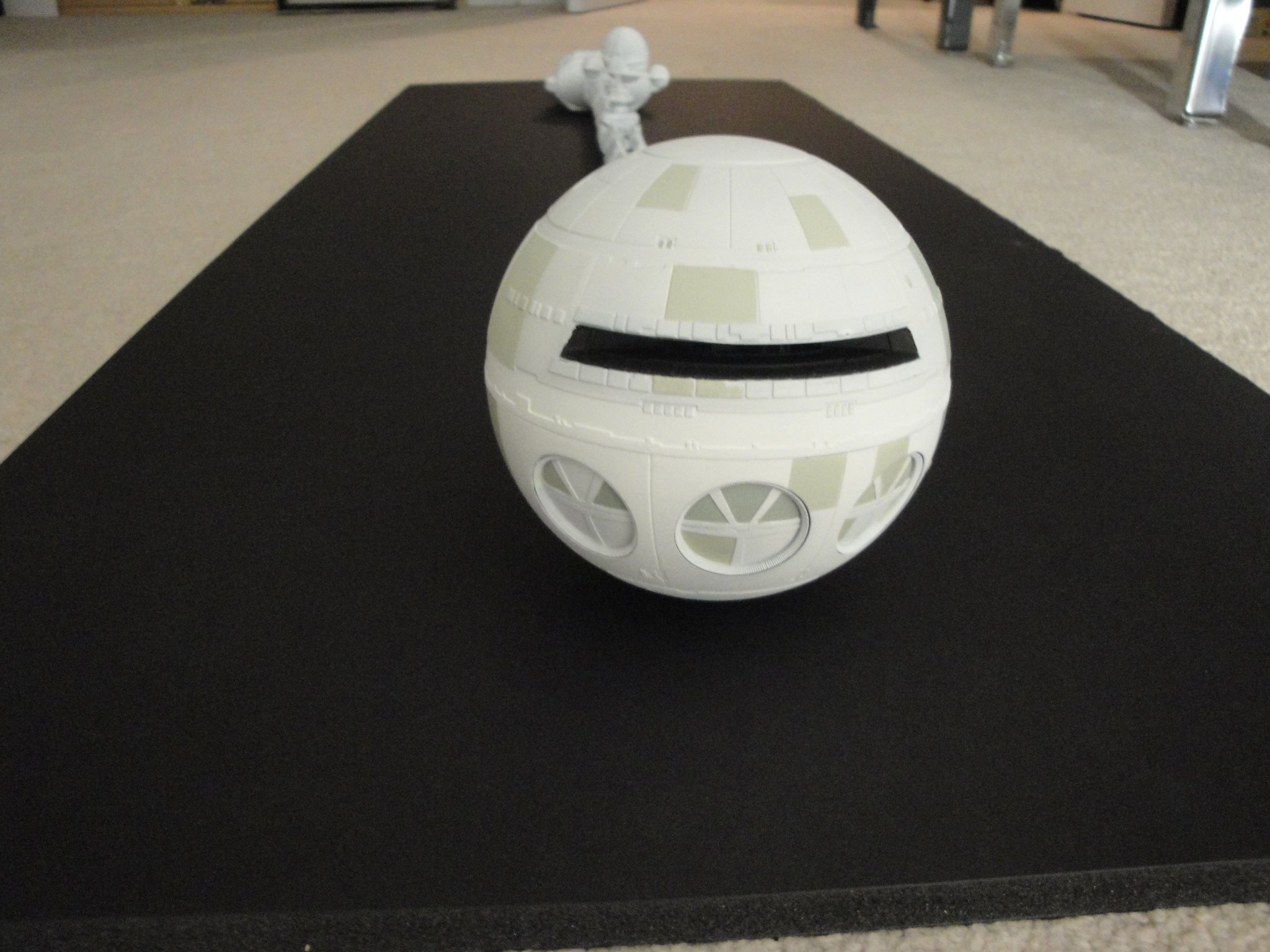
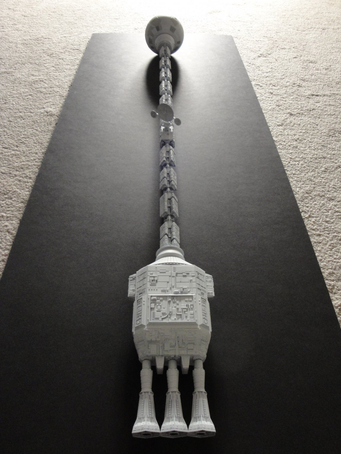
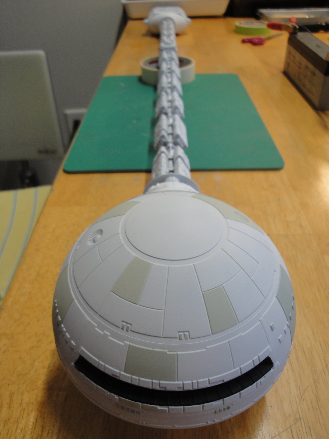
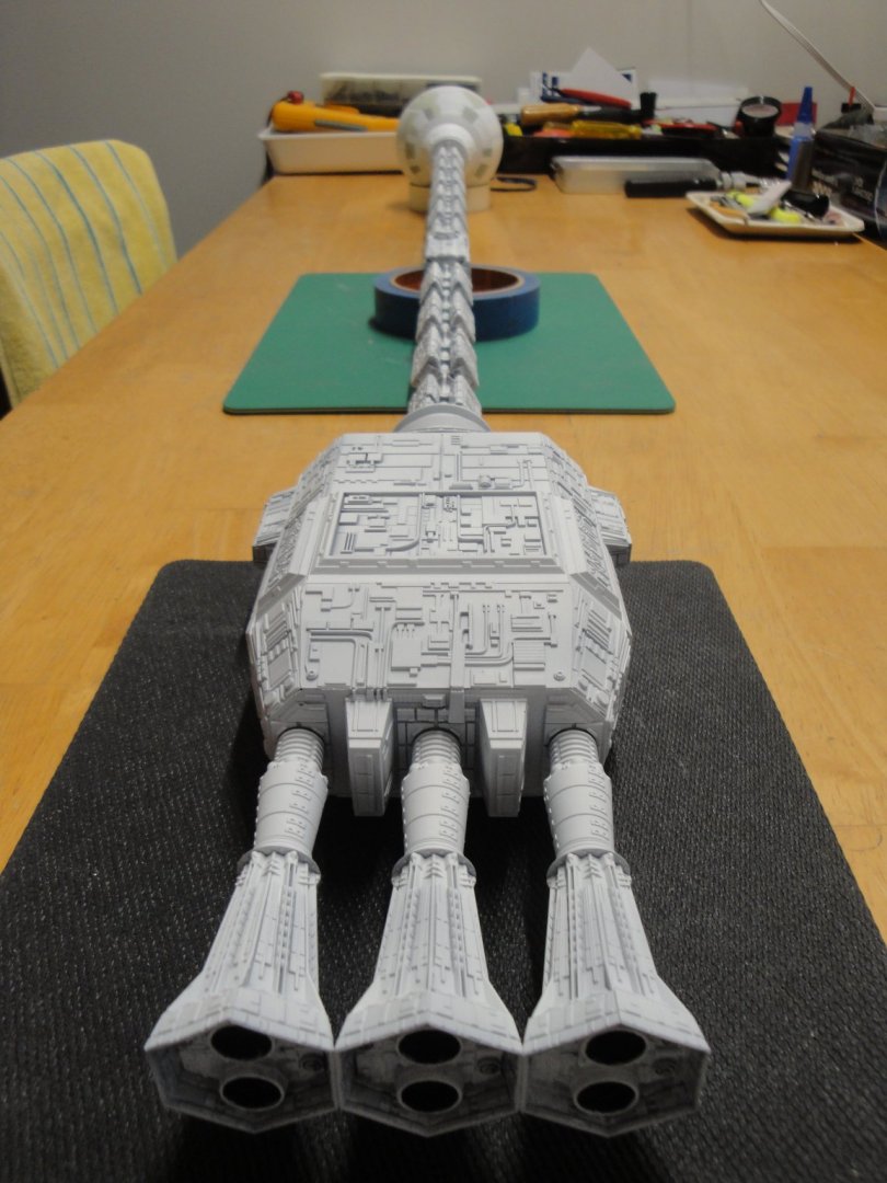
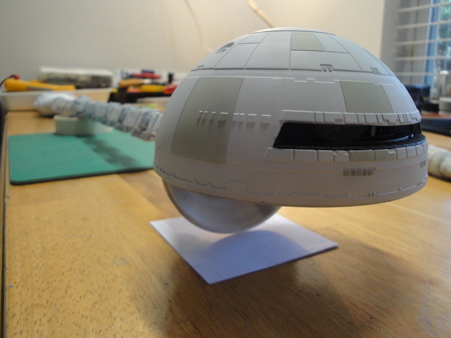
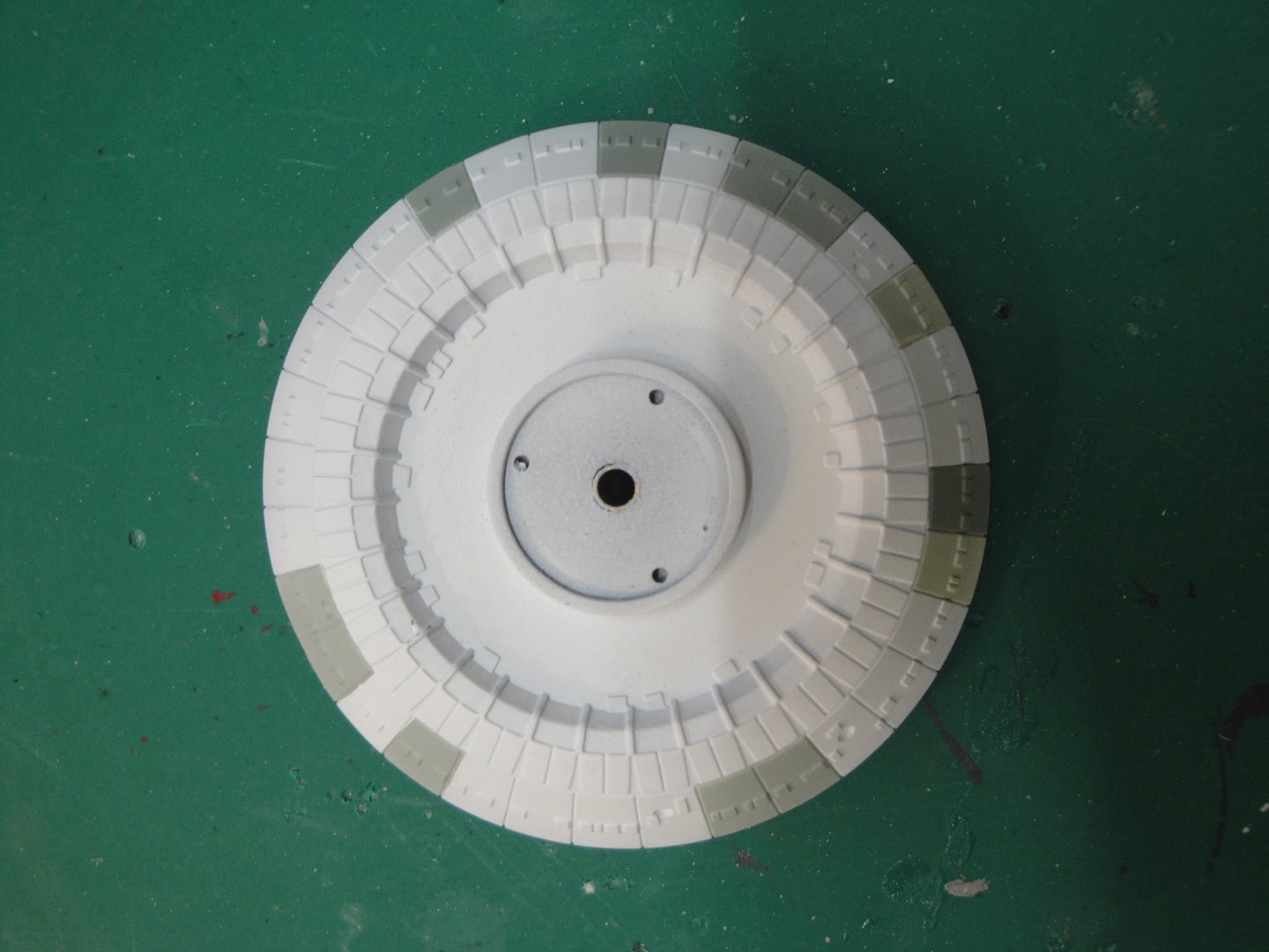
Trying to finish this Discovery vessel. I am still waiting for "Cold" white LEDs to finish the cockpit and create the light chamber with both halves of the sphere. In the meantime, I did paint some panels, as seen in the movie and other reference materials. It takes a lot of masking, but the result is worth it: There are basically three shades of paint used on these parts. The sphere is also getting a similar treatment: And the bottom part is getting ready for its white coat and panels tainting: There are different schools for painting the panels, including a study of the movie and still frames which is not the easiest to do. I am basing my approach on the fantastic model of the Discovery done by a Japanese company. Their model (absolutely unreachable for us at $13,000 in the scale of 1/10 of the movie prop) is the closest and most realistic rendition ever made of the Discovery. My model is an approximation of their masterpiece..... Yves
- 119 replies
-
- 14
-
-
B-25 Mitchell "Meet Miss Runyon" by Javlin-HK-1/32
yvesvidal replied to Javlin's topic in Non-ship/categorised builds
Beautiful. The early Mustang is a little marvel, too. Yves -
B-25 Mitchell "Meet Miss Runyon" by Javlin-HK-1/32
yvesvidal replied to Javlin's topic in Non-ship/categorised builds
Beautiful cockpit. It helps to work at 1/32nd or 1/48th scale..... I cannot stand the 1/144th of my Space Discovery interiors. Yves -
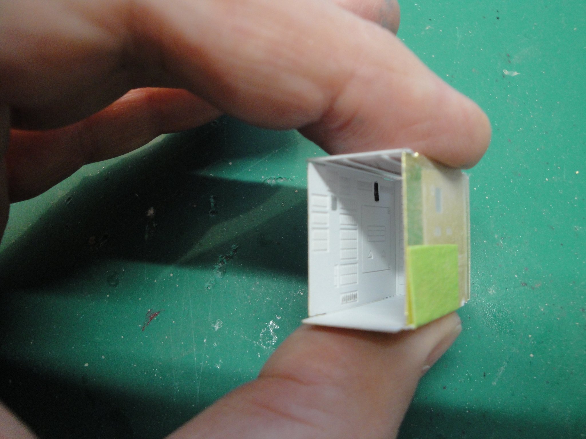
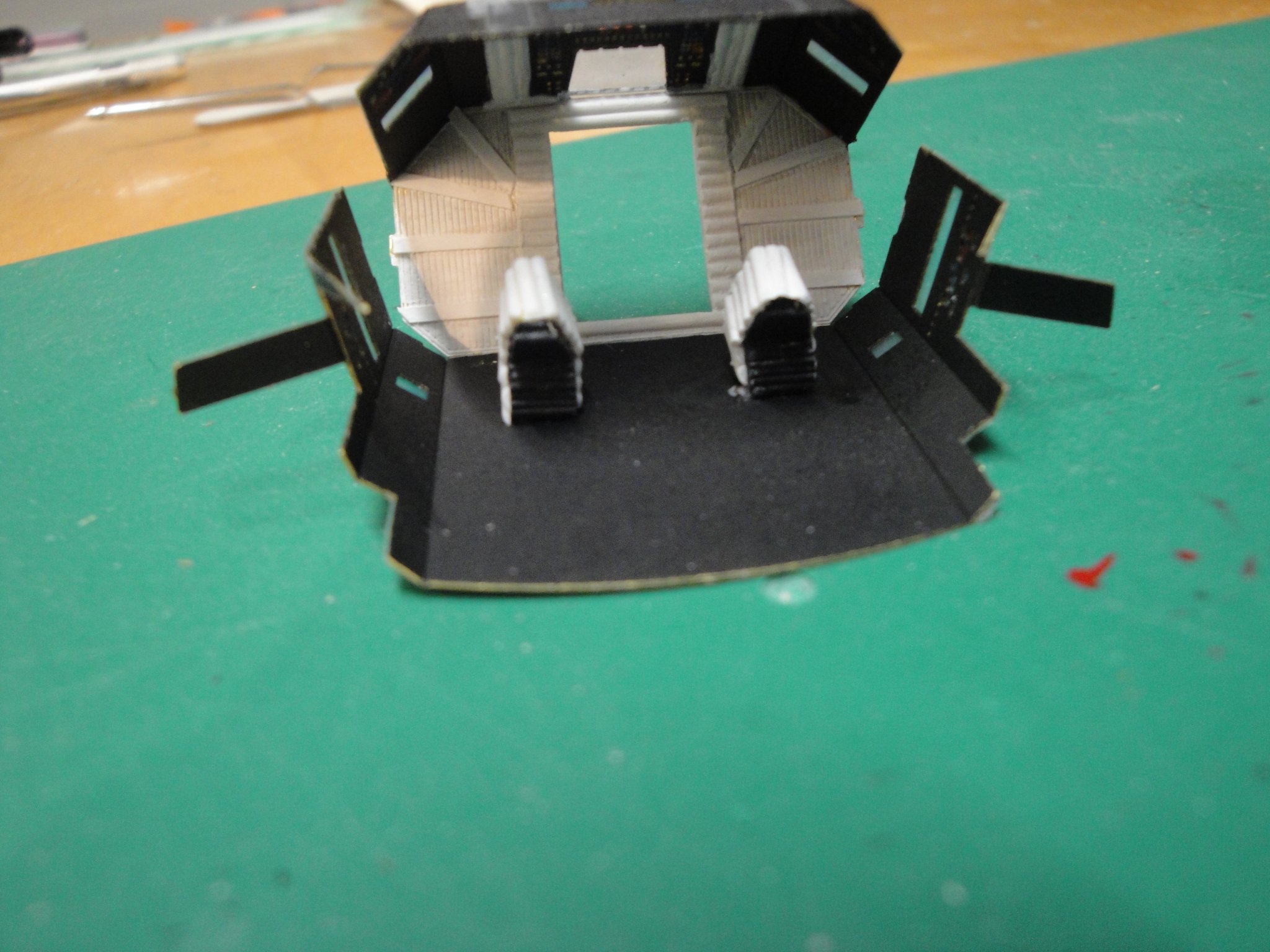
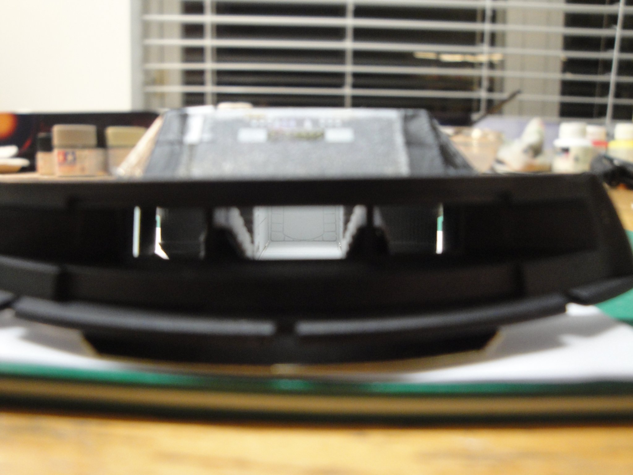
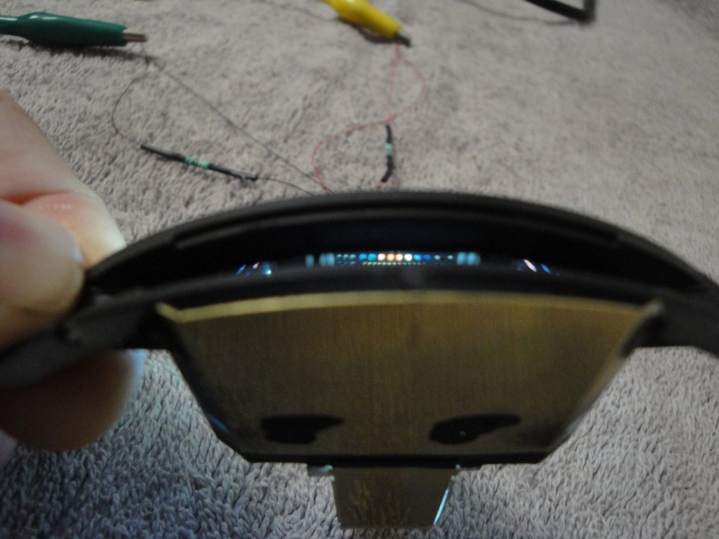
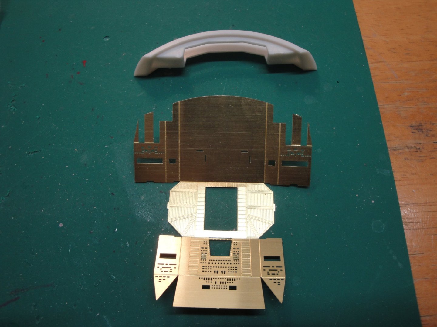
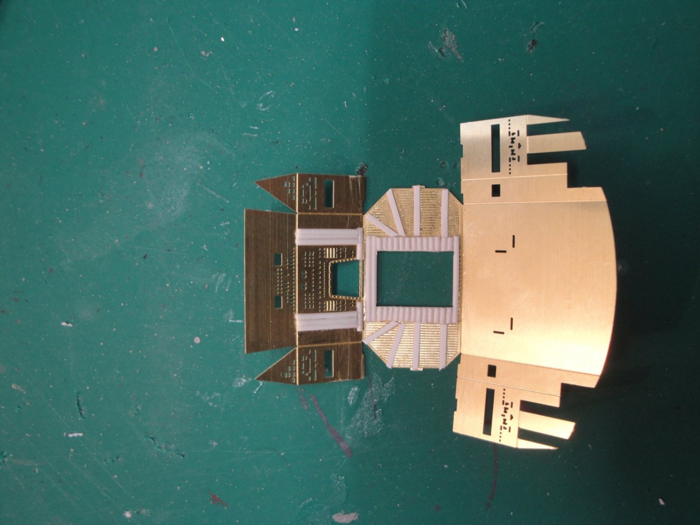
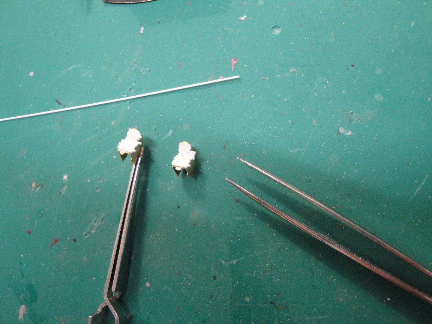
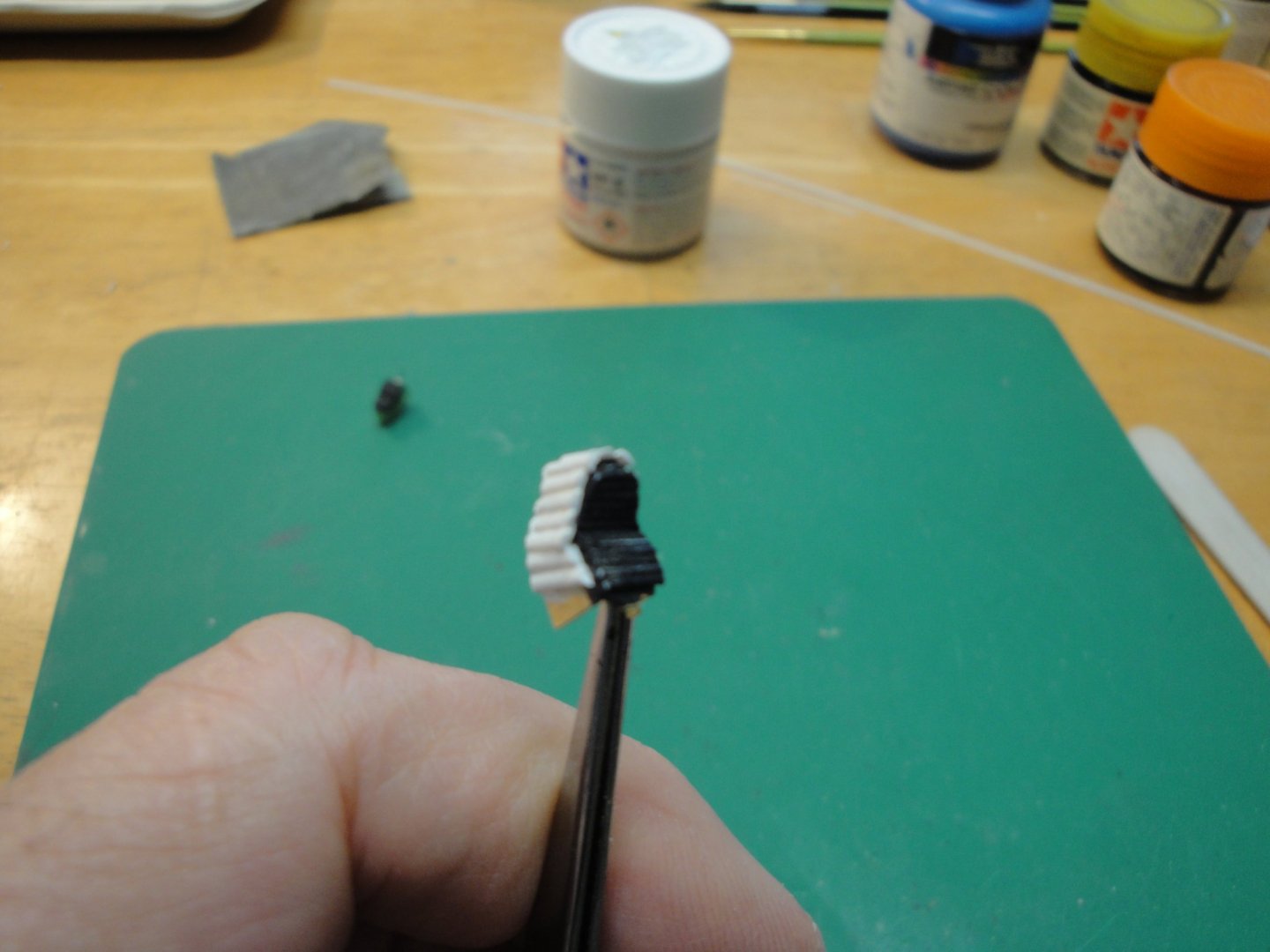
Some progress on the crew space, the sphere. As mentioned earlier, I am limiting myself to the cockpit and the hallway right behind it. The Paragrafix kit also offers the main corridor between the exit door and the deck (the exit David Bowman uses after being denied access to the ship by the neurotic HAL 9000) as seen below: The PE set has also a couple of parts to depict the emergency hatch: The cockpit is basically composed of one main piece that is folded in multiple directions and of two seats: The brass is of excellent manufacture and rather thick, which is ideal to keep the walls flat and straight. The cuts representing the various screens and controls are exquisitely done and mimic perfectly the movie prop. However, they are flat like all PE parts. Using styrene pieces, it is possible to make the deck more realistic. I am using half-round 1 mm pieces and the tiniest flat strips you can find: The rear hallway is another part that is folded to form the corridor: Again, lots of precision and details are available. The black box on the left is the HAL 9000 eye. The seats are microscopic and require an intricate folding: Again, I am using 0.5 mm round strips to simulate the cushions where the crew can sit. The outer shell of the seats is made using the 1.0 mm half-round styrene bits. Overall, this cockpit is a lot of work for what you end up seeing through the front shield. The deck is pretty much ready to be closed: You can see some of the colored controls, done with a piece of Scotch tape glued on the PE: I am using clear color Tamiya acrylic paint applied with a tiny brush. Other sections are done with colored markers. It is very, very small and frankly a waste of time. But it looks good. Only a fraction of what you see below will be visible when the deck is placed behind the window frame: My camera is completely unable to focus and take decent Macro shots. Maybe it is better this way, as you cannot see my sloppy work.... The deck is glued to the window frame: here again, perfect fit from the PE parts. Below is pretty much what you can see..... My next work is to seal all the cracks with thick cement and paint the seams matt black. I want to make sure that the light will not leak and only comes from the controls and from the hallway. The entire sphere will be the light chamber. Honestly, an enormous amount of work for very little return. Modelers attempting the PODs bay will have more fun but also a lot more work. Yves


- 119 replies
-
- 21
-
-
Very efficient obviously !!! I'd rather land on the water...and swim to the boat. Yves