yvesvidal
-
Posts
3,641 -
Joined
-
Last visited
Content Type
Profiles
Forums
Gallery
Events
Everything posted by yvesvidal
-
 Is that the Bentley or a Fiat? Yves
 -
Andy, you finished a real marvel. I still remember one of my best friends some 45 years ago, as he tried to build that model (or a previous iteration of it). His did not complete in such a nice way.... but we were just kids playing and the glues, paints and putties were not what they are today. HUMBROL was dominating the market in Europe and that is all you had. Yves
-
That is exactly how the kit instructions describe the gluing of the paper. I decided to go with something which has a little bit more grain.... Yves
-
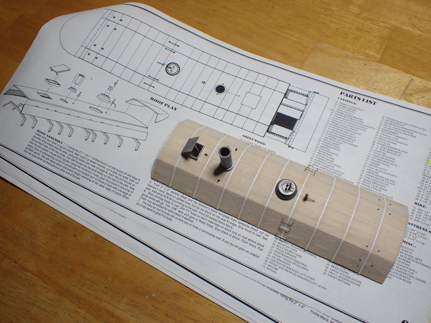
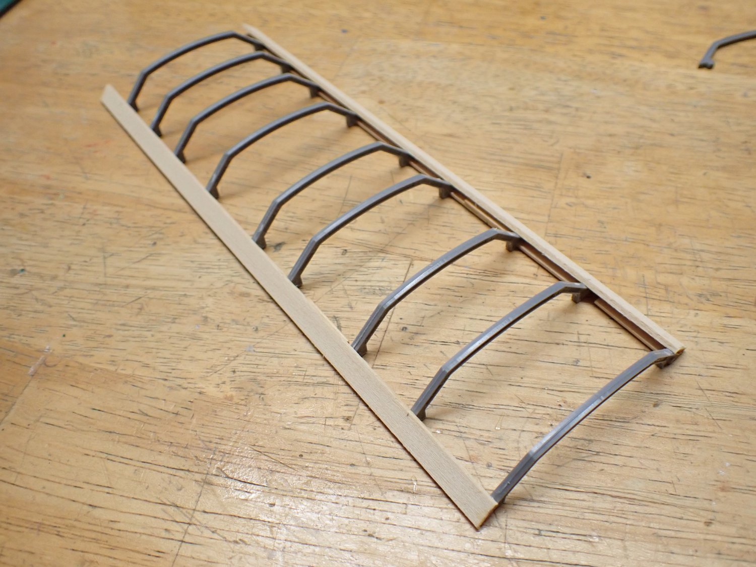
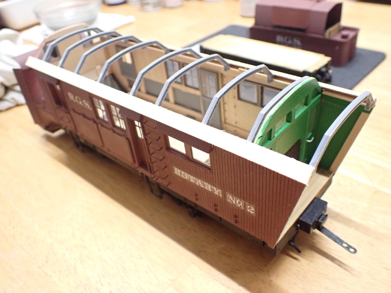
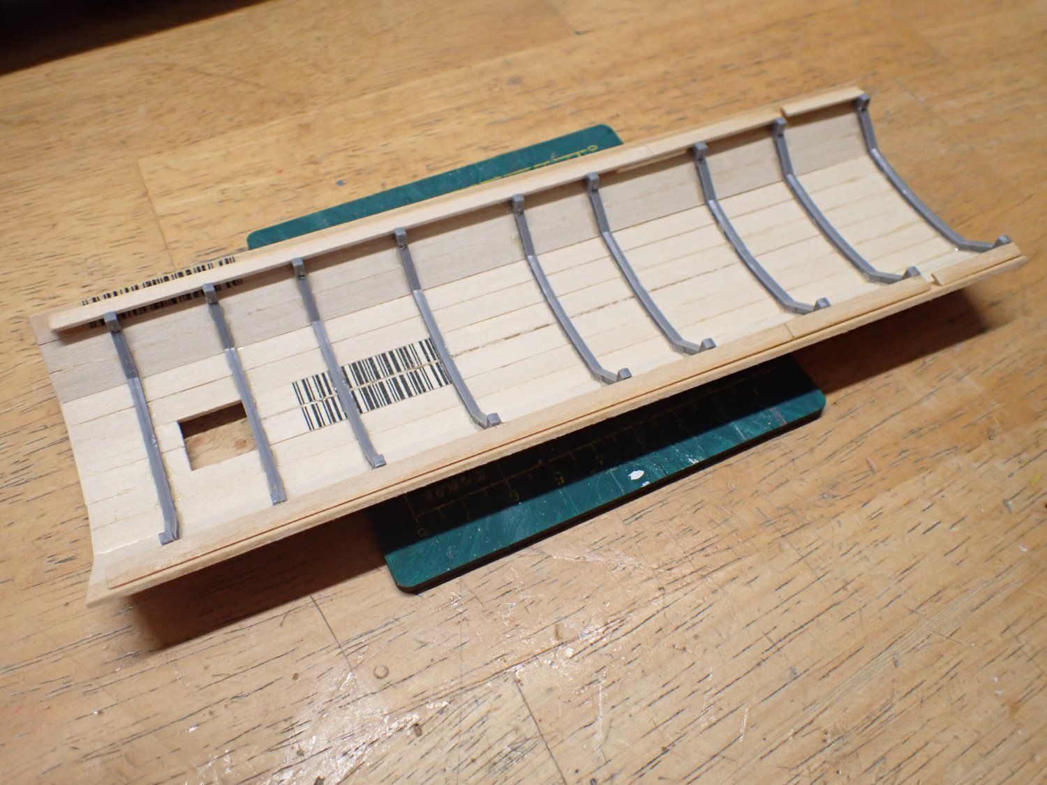
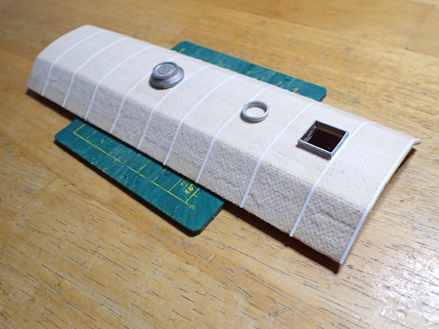
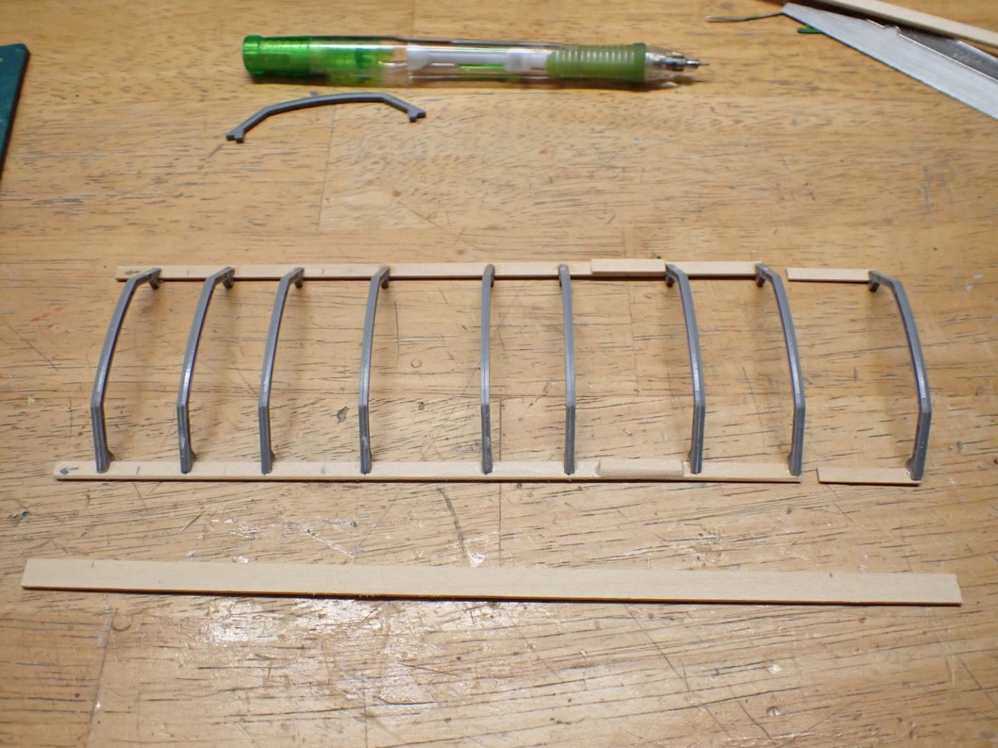
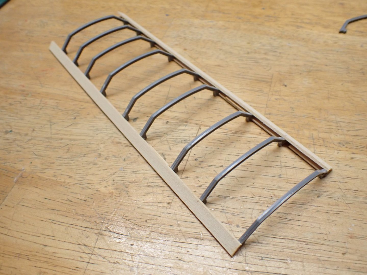
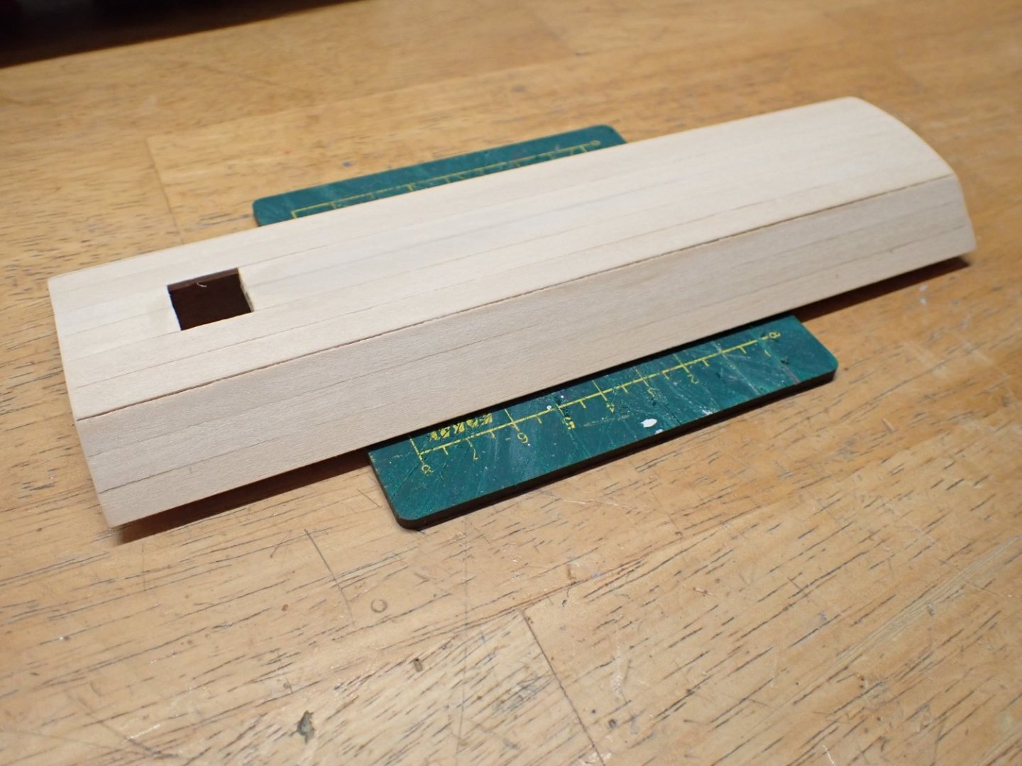
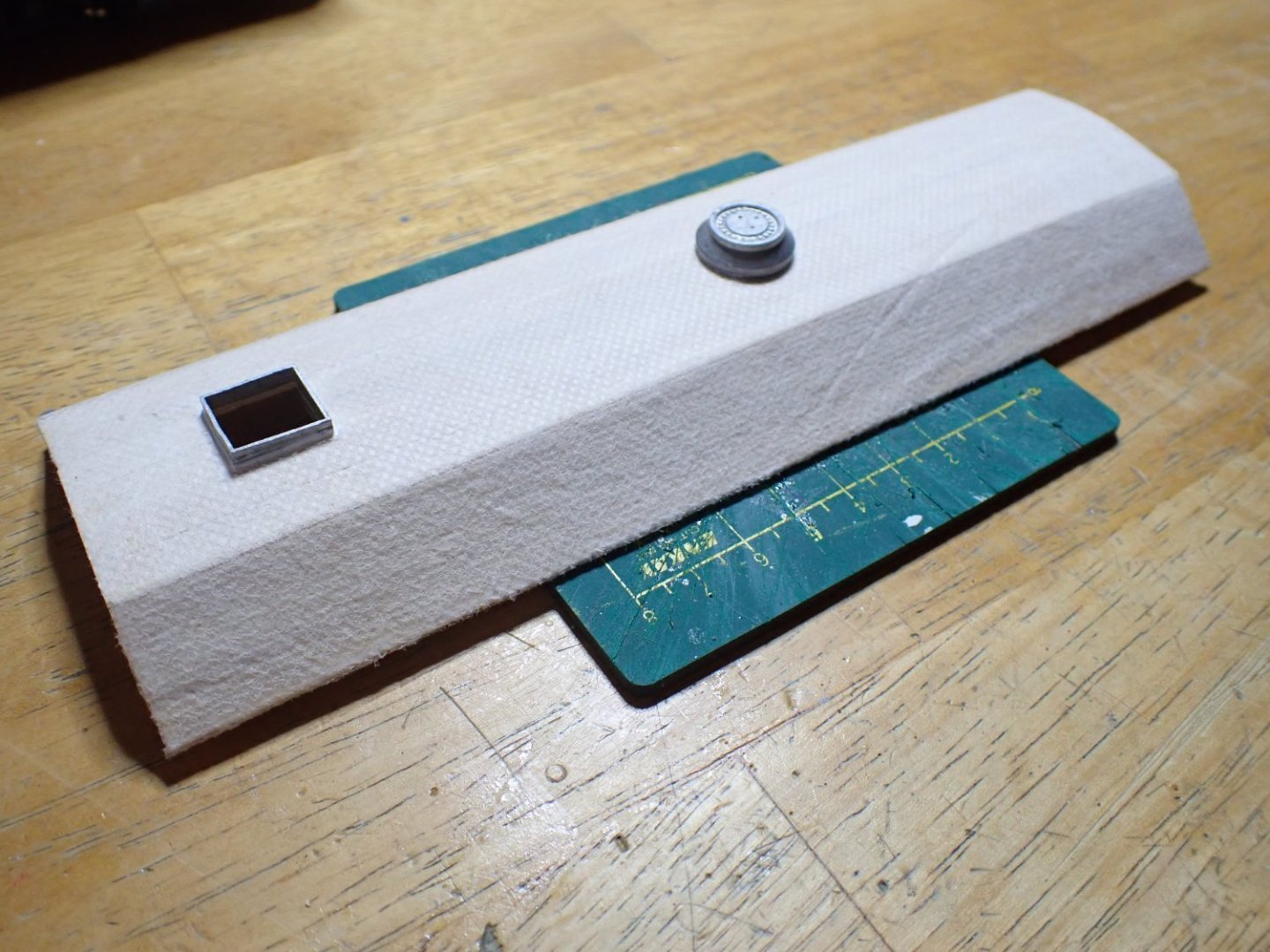
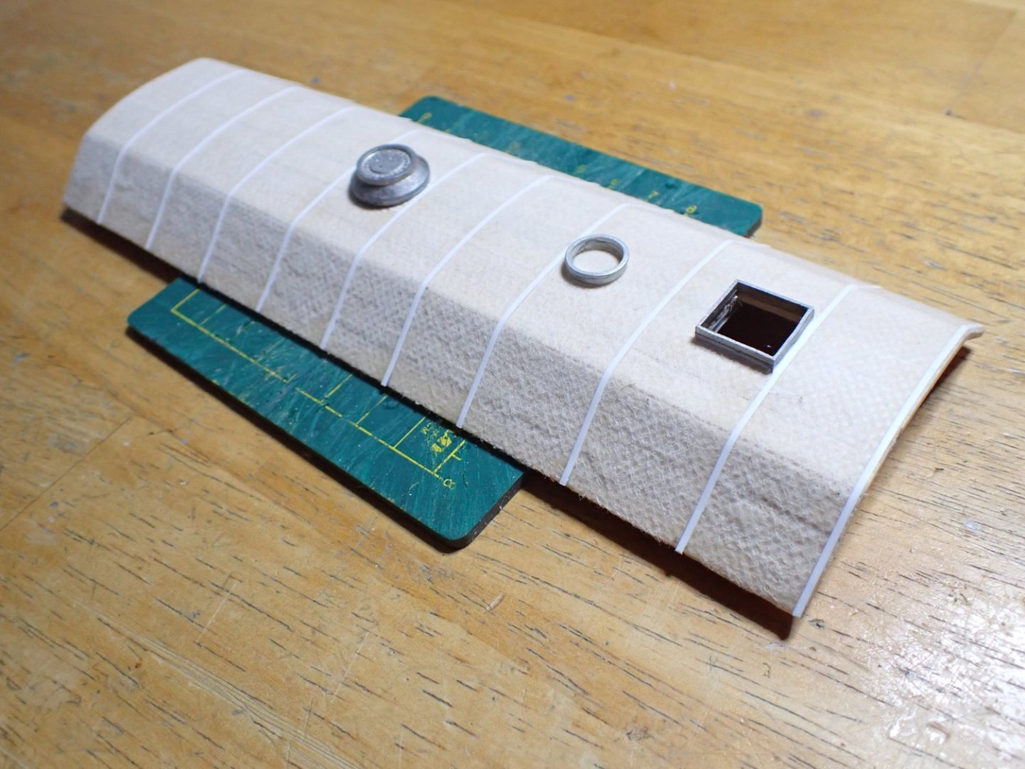
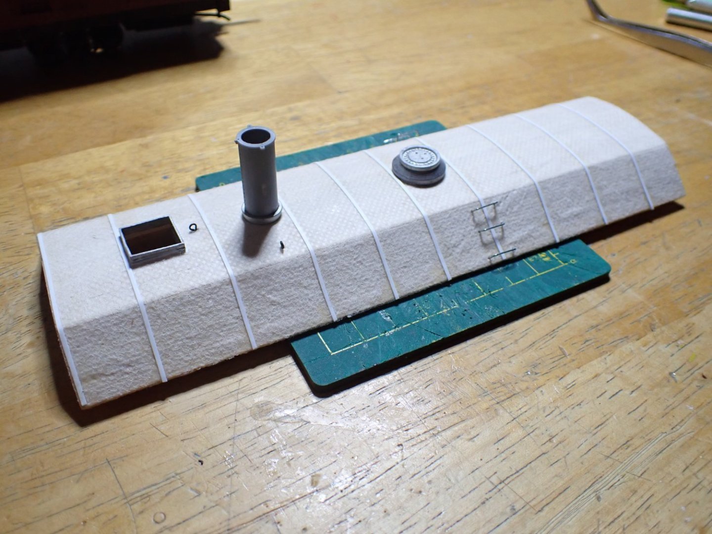
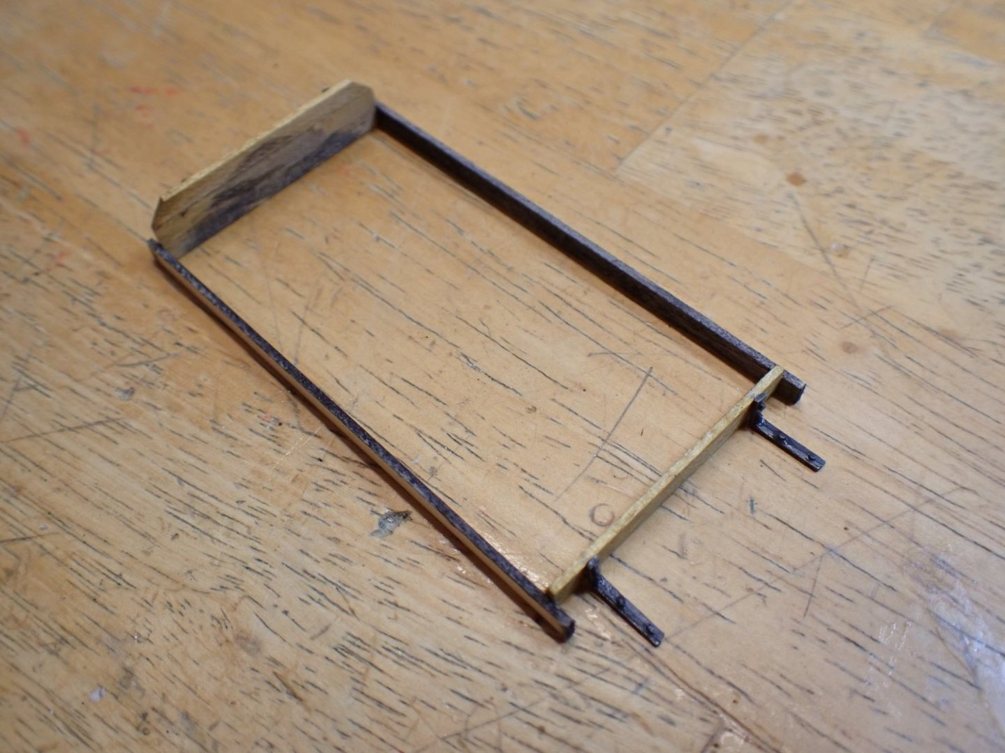
I think we are due for an update. I have been working on the roof of the rotary plow which is actually much more complicated than it seems: Above is the final result before painting. It starts with two strips of wood and a few plastic frames: The cuts at the rear, are designed to accommodate the rear bulkhead. The original kit calls for a large scribbed sheet of wood that you have to cut. I decided instead, to go with a regular planking, treating it like a hull. Nobody on this forum will complain about that.... Planking is complete: It fits very rather well. The roof will be permanently glued, since I have no intent to detail the interior. The next step is to glue some kind of fabric. That piece of fabric was missing from my kit and so I decided to use some kind of fabric used for delicate packaging: it is glued with PVA glue, diluted with water. This is supposed to mimic the tar covered roof, used on this kind of Maintenance of the Way cars. Little by little, more details are added to the roof: And it is now ready for paint: Yves


- 102 replies
-
- 15
-

-

-
Beautiful hull. It is taking its final shape. Yves
-
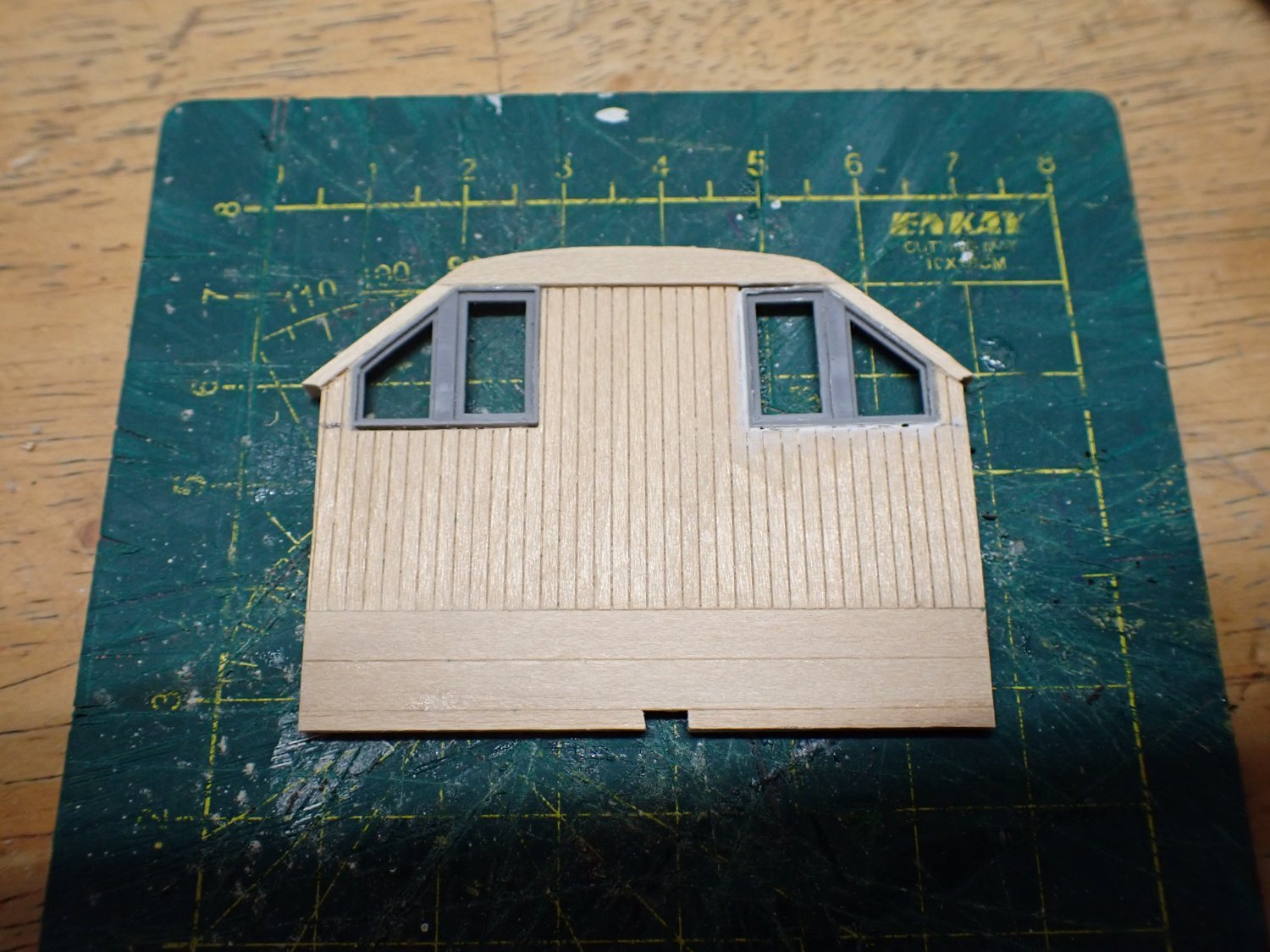
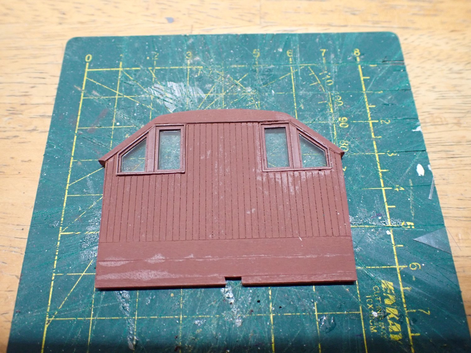
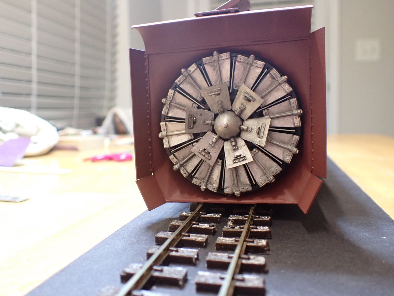
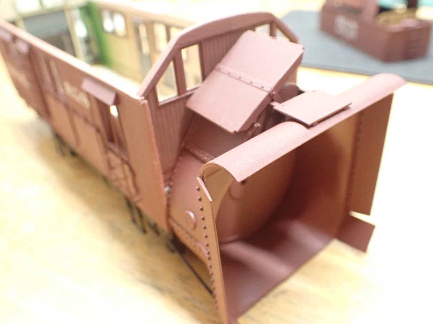
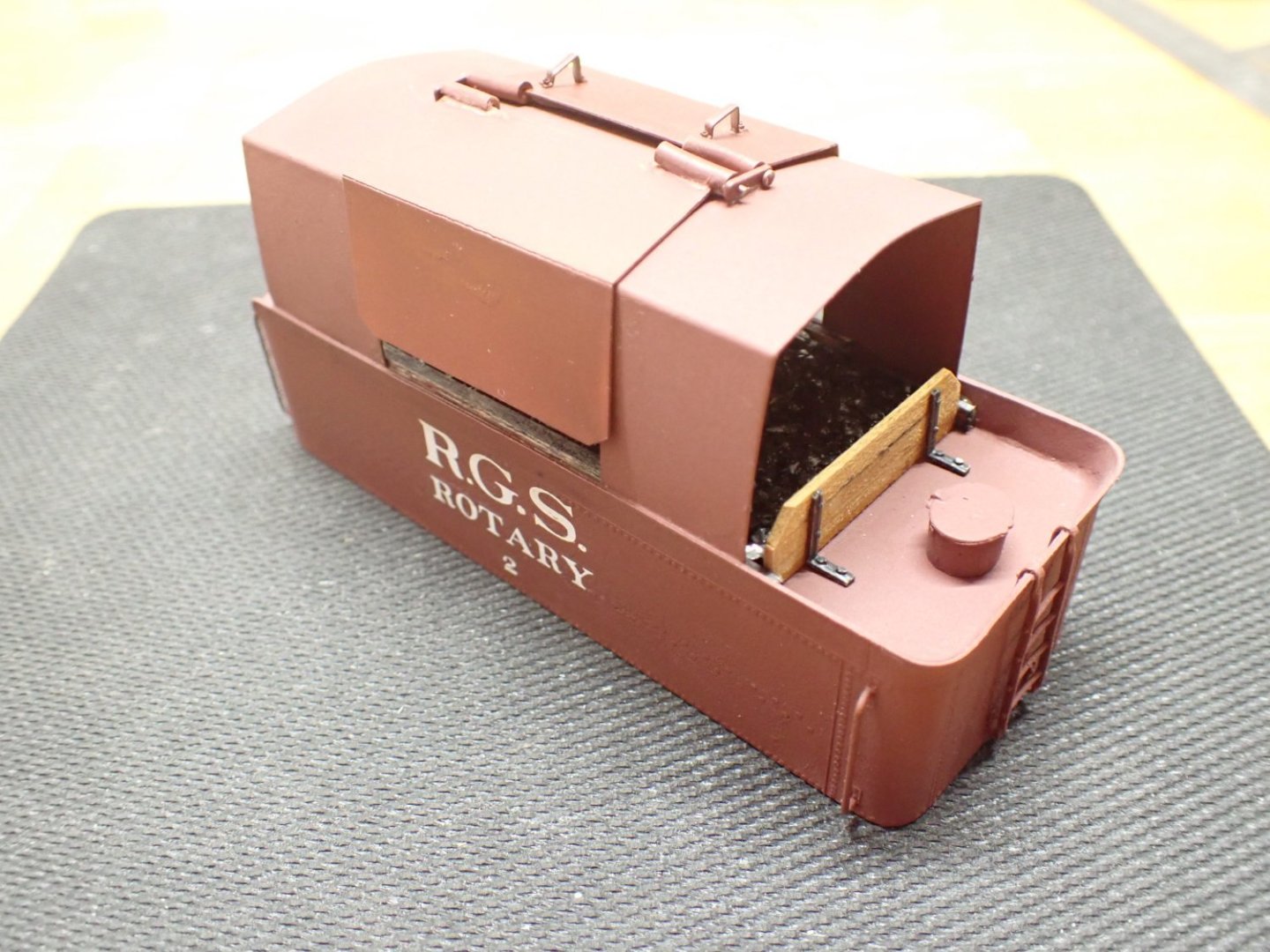
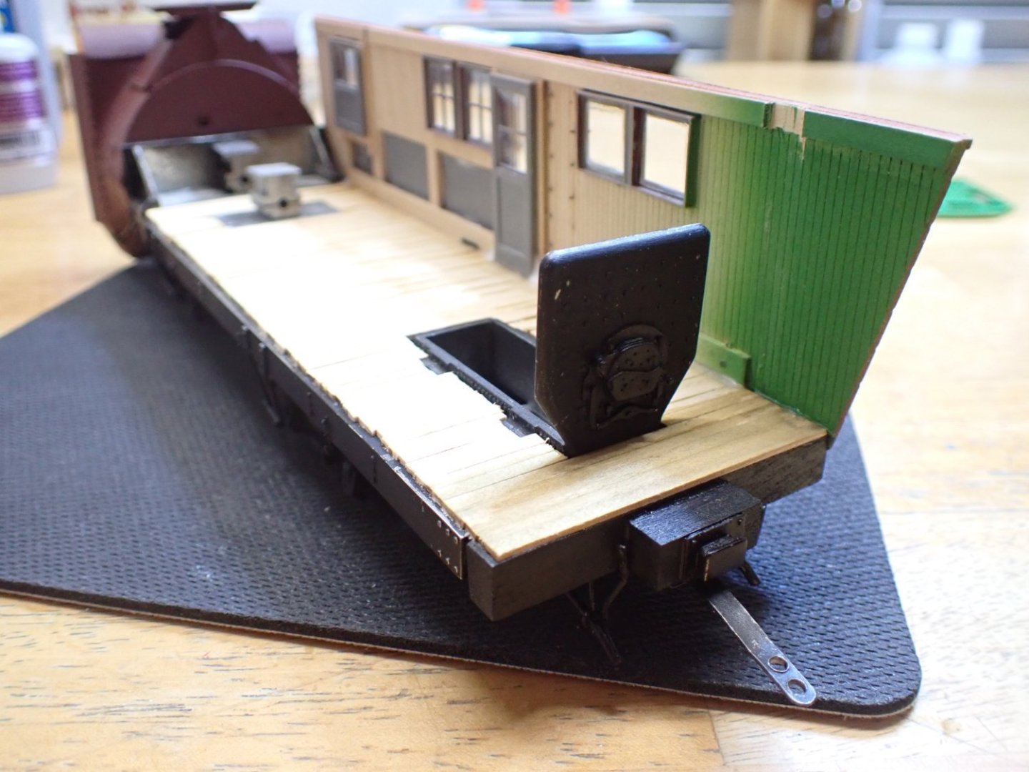
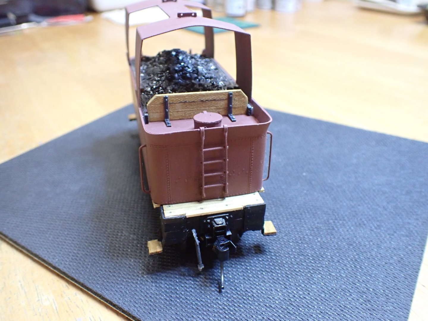
The front wall is now finished: The covers to protect the coal from the snow, are difficult to install. I tried to make them movable and got some moderate success: I may work some more on them, as I am not completely happy with the results. Overall, the snowplow is starting to look like the real thing: More pictures to come.... Yves


- 102 replies
-
- 15
-
-
-
I was in Annapolis this weekend attending the Sailboat show. The Pride of Baltimore 2 was there, docked and available for the public to tour. What a beautiful sight! That ship is quite impressive and the most interesting part is how slanted the masts are. I have never seen something like that on a period ship or even on a more recent vessel. The deck had all the guns in place plus (unfortunately) all the modern safety stuff that are now required, to navigate. Yves
- 51 replies
-
- 2
-
-
- Model Shipways
- Baltimore Clipper
- (and 1 more)
-
The diorama looks even better than the Falcon bird. Amazing work. Yves
-
That is a beautiful model. I will follow your progress. Yves
- 68 replies
-
- 2
-
-
- Sanson
- Artesania Latina
- (and 2 more)
-
Absolutely superb. Great presentation, too with this five folds picture. I hope you will start a Build Log for the Yamato. Yves
-
Barncave Shipyard by mbp521 - Scale 1:1
yvesvidal replied to mbp521's topic in Non-ship/categorised builds
What a beautiful workshop. Honestly, this is perfection and I am very jealous and envious. Chaperon is in place, but you will need to protect it from the dust. Yves -
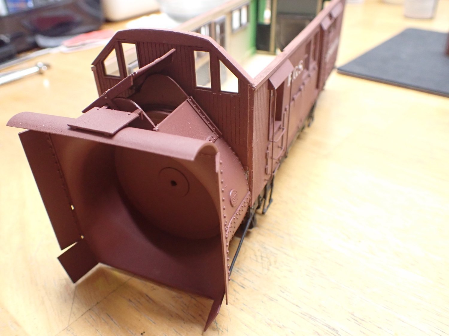
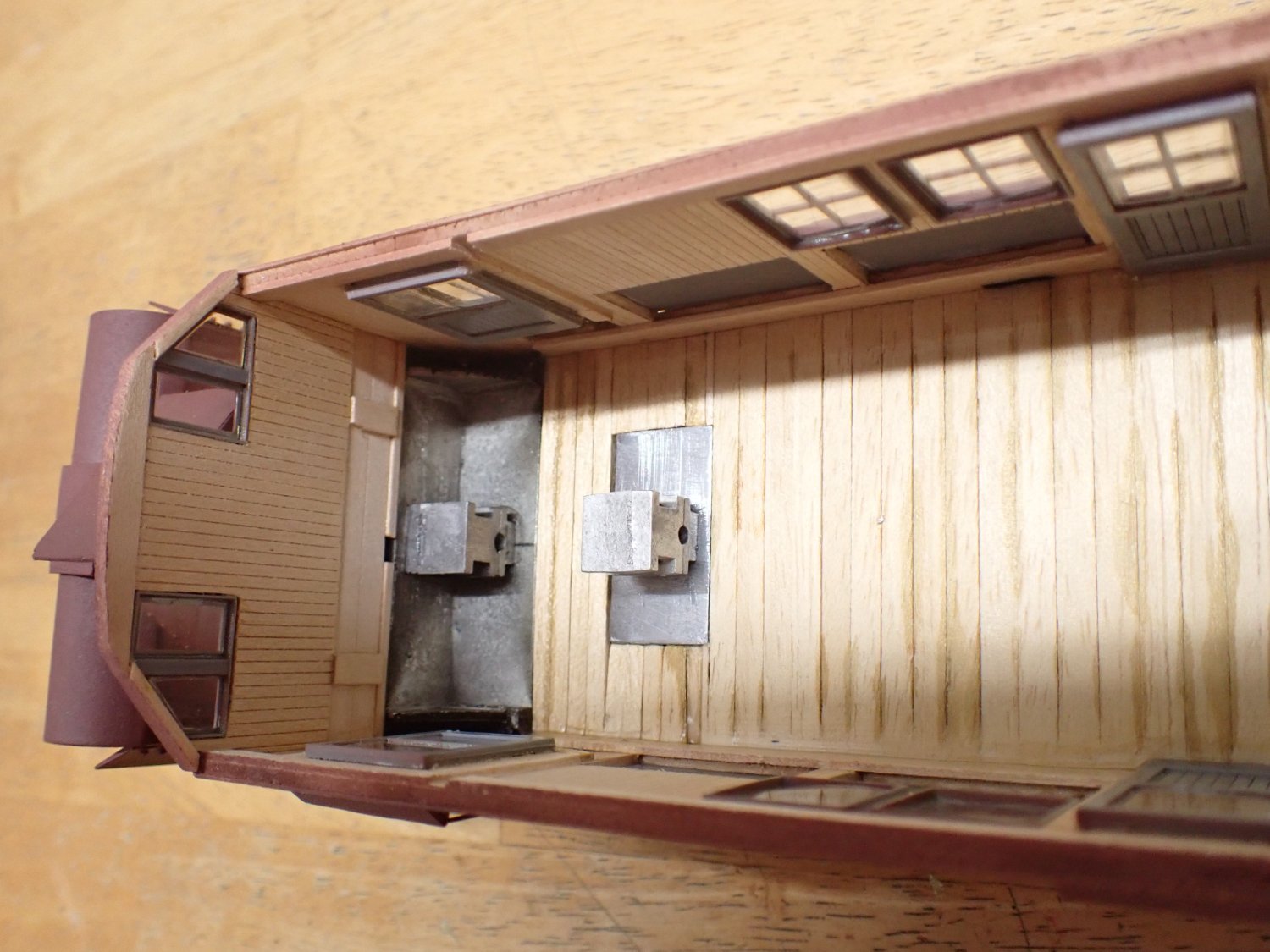
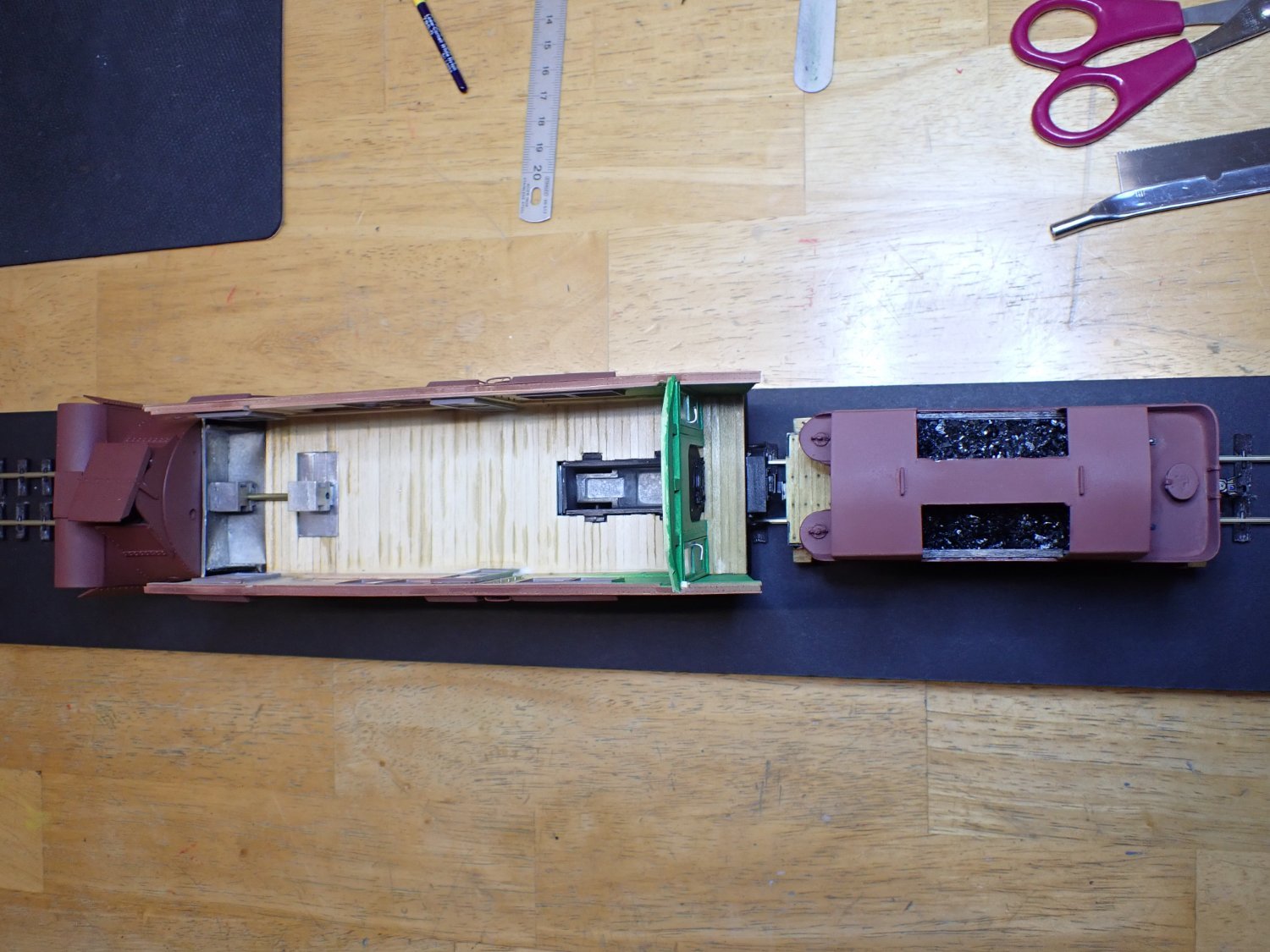
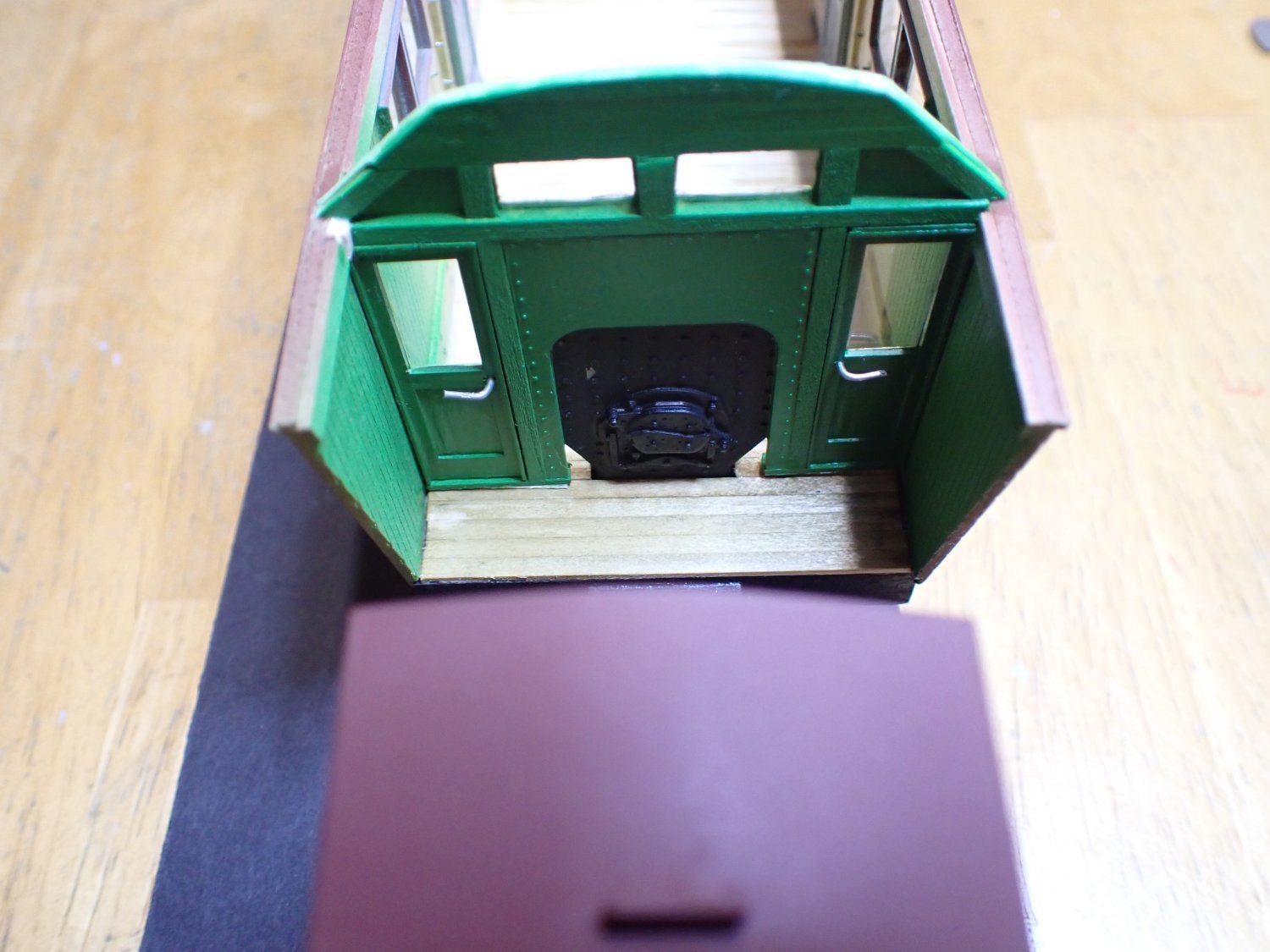
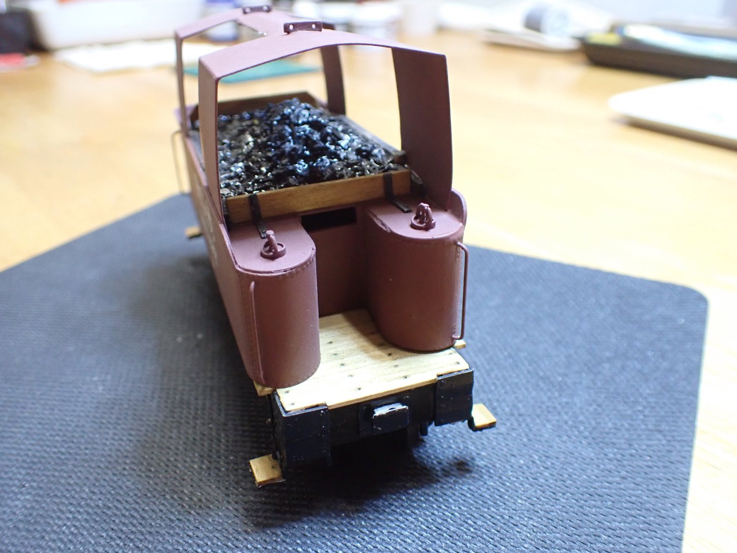
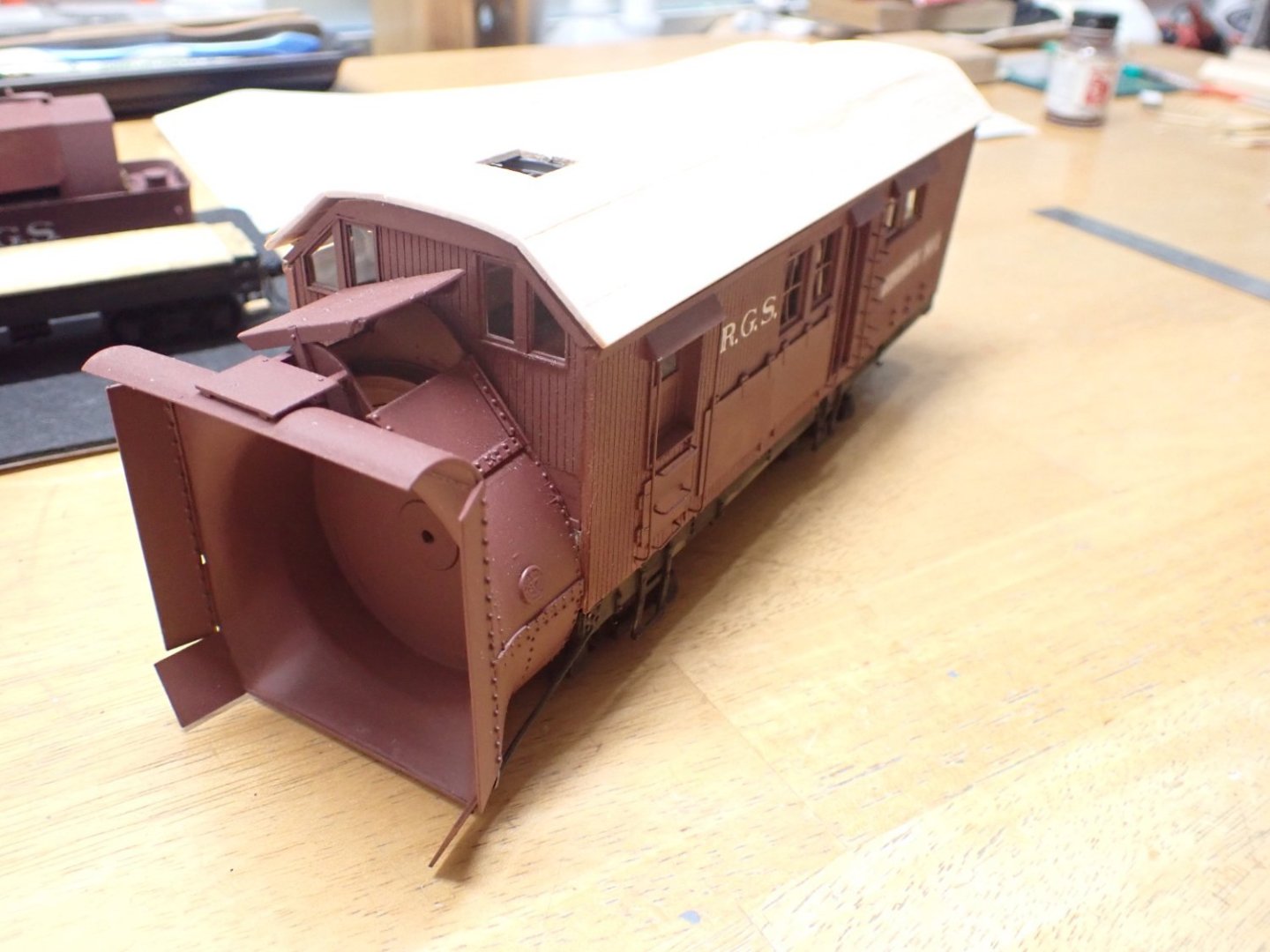
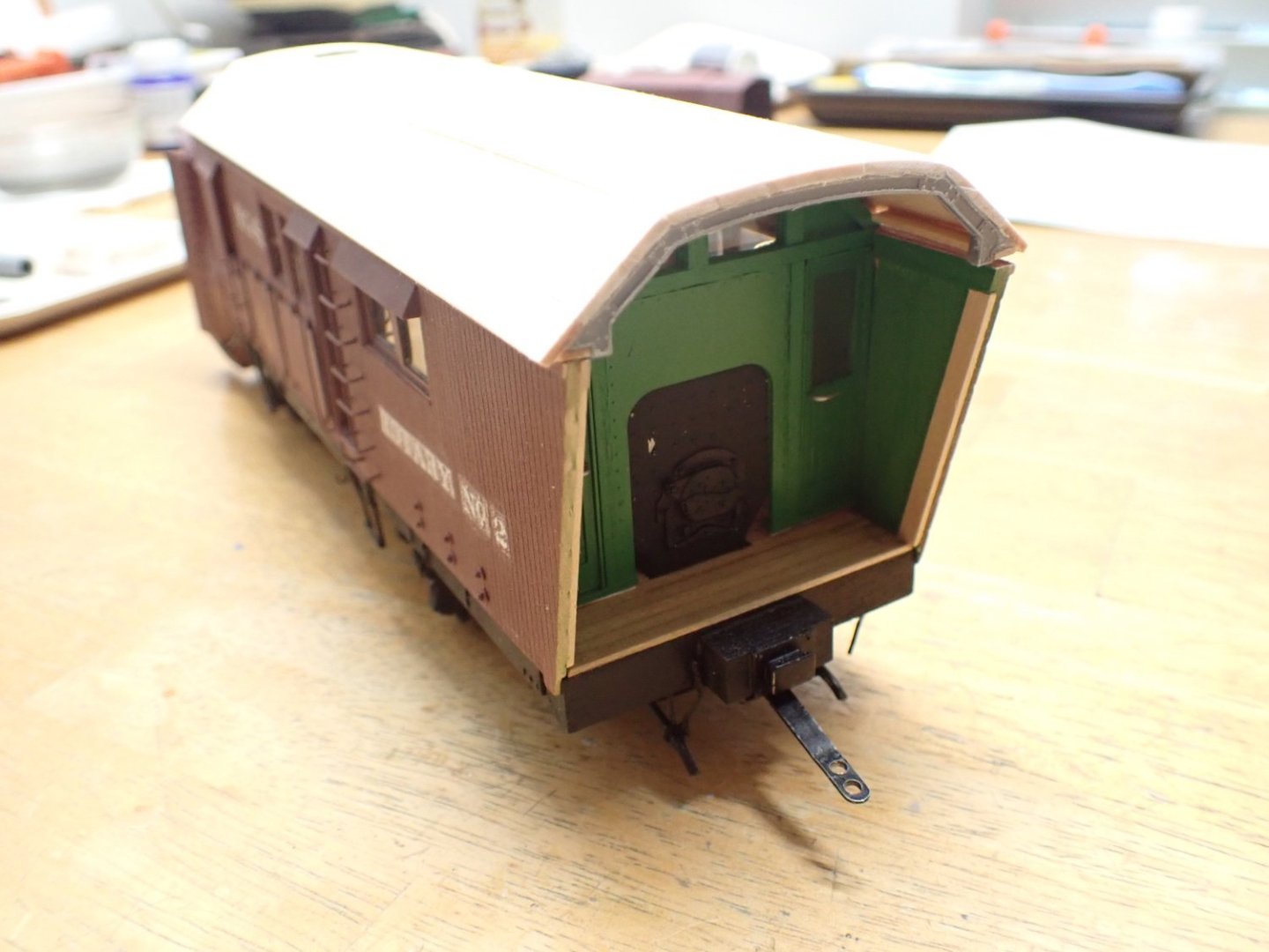
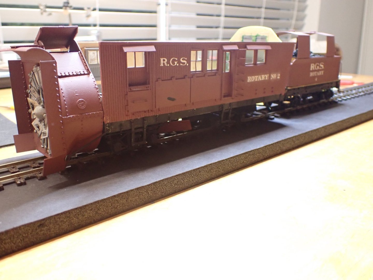
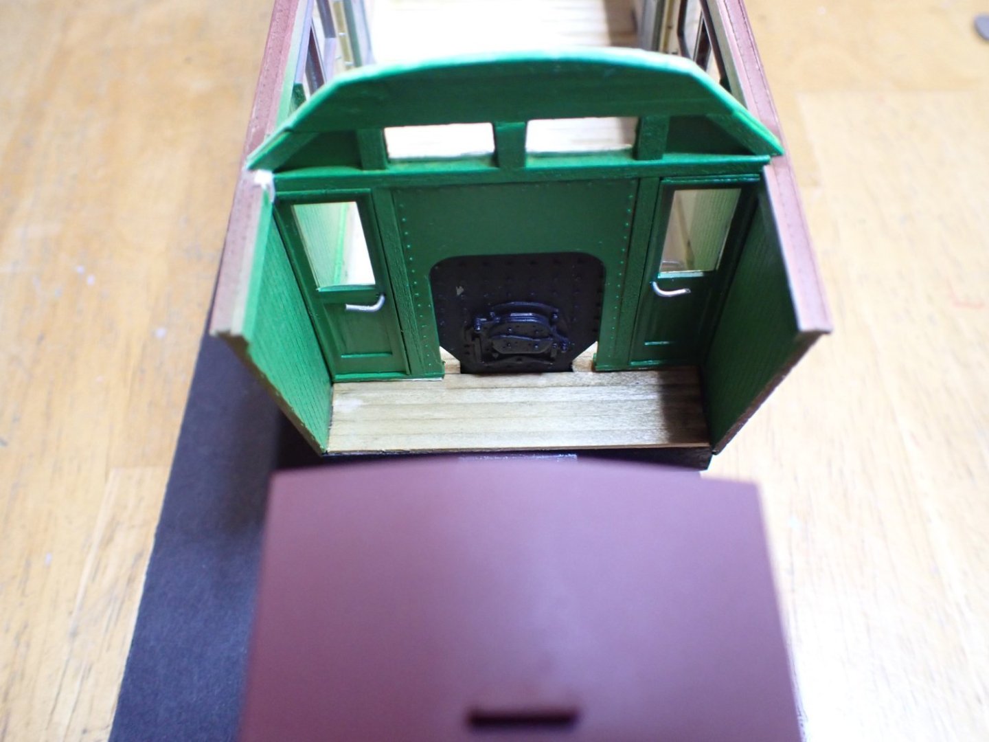
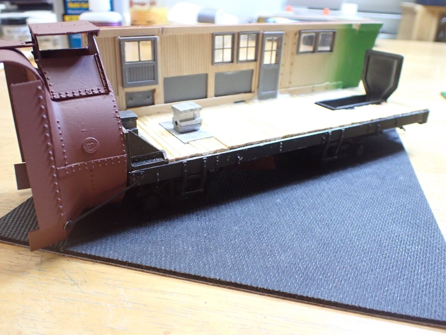
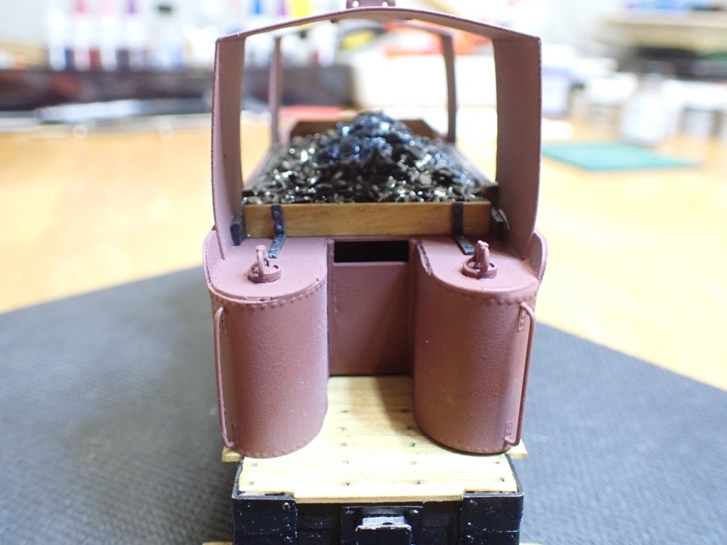
Main walls are in place. Below is where we stand: I am still missing the front wall and the cabin wall, inside. Above, you can clearly see that the snowplow was designed for regular track gauge. In our case, we are using the narrow gauge trucks (On3 at 1/48 scale). The tender on the other hand, is showing its true origin designed as a narrow gauge piece of equipment for RGS (Rio Grande Southern). The tank is not glued to the chassis, yet. I need to finish the covers before doing anything else. Ready to swallow and jettison, tons of snow.... The furnace through which coal was shoveled in. Yves


- 102 replies
-
- 12
-
-
-
Bugatti Type 35B by CDW - FINISHED - Italeri - 1:12 Scale
yvesvidal replied to CDW's topic in Non-ship/categorised builds
Craig, I have the Mefistofele FIAT and the Bentley on my shelves. I will wait for your Build logs, before starting them.... :-)) Yves -
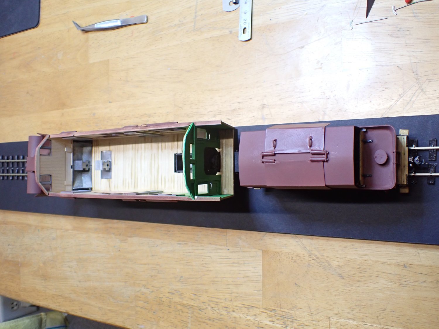
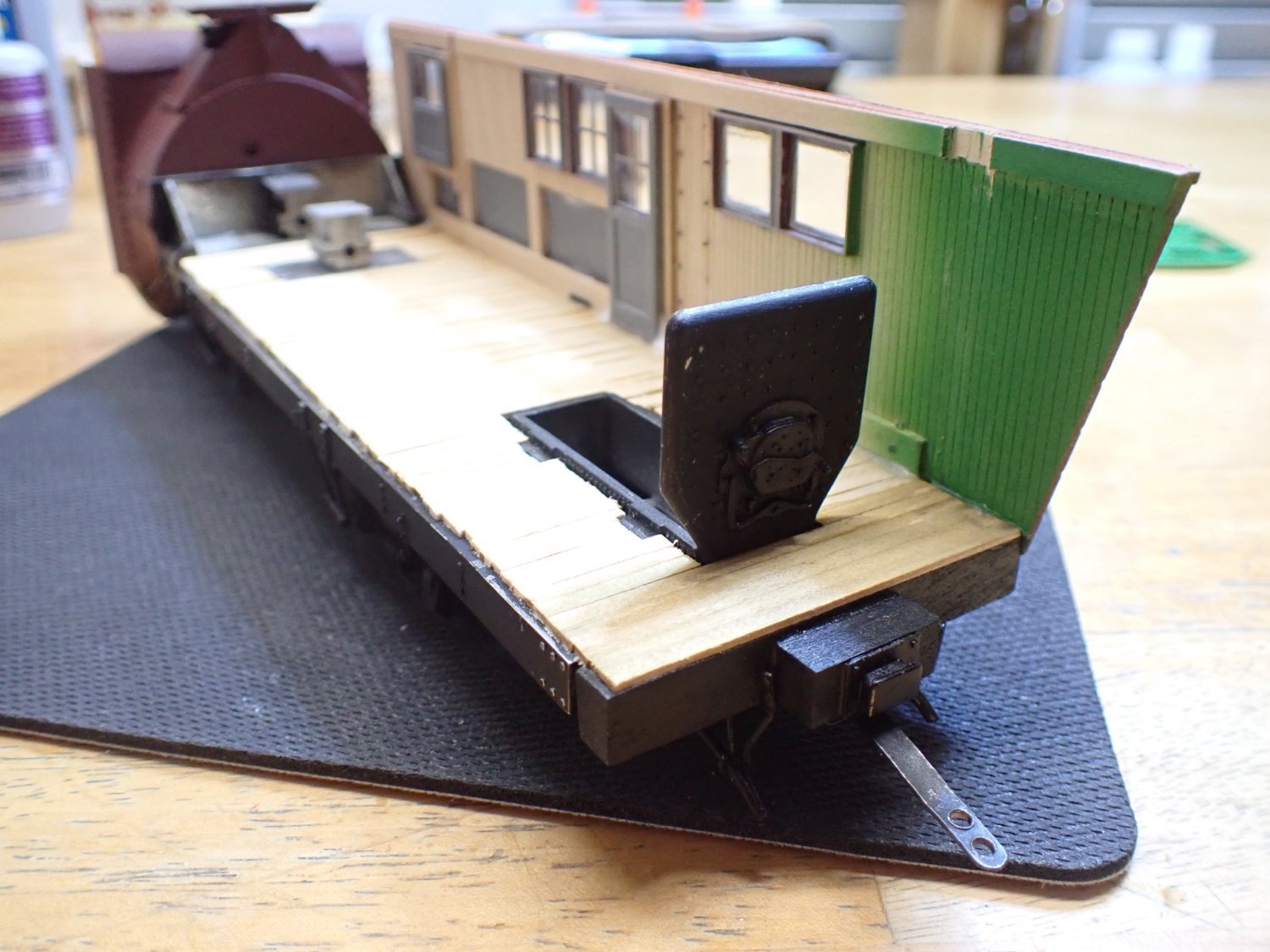
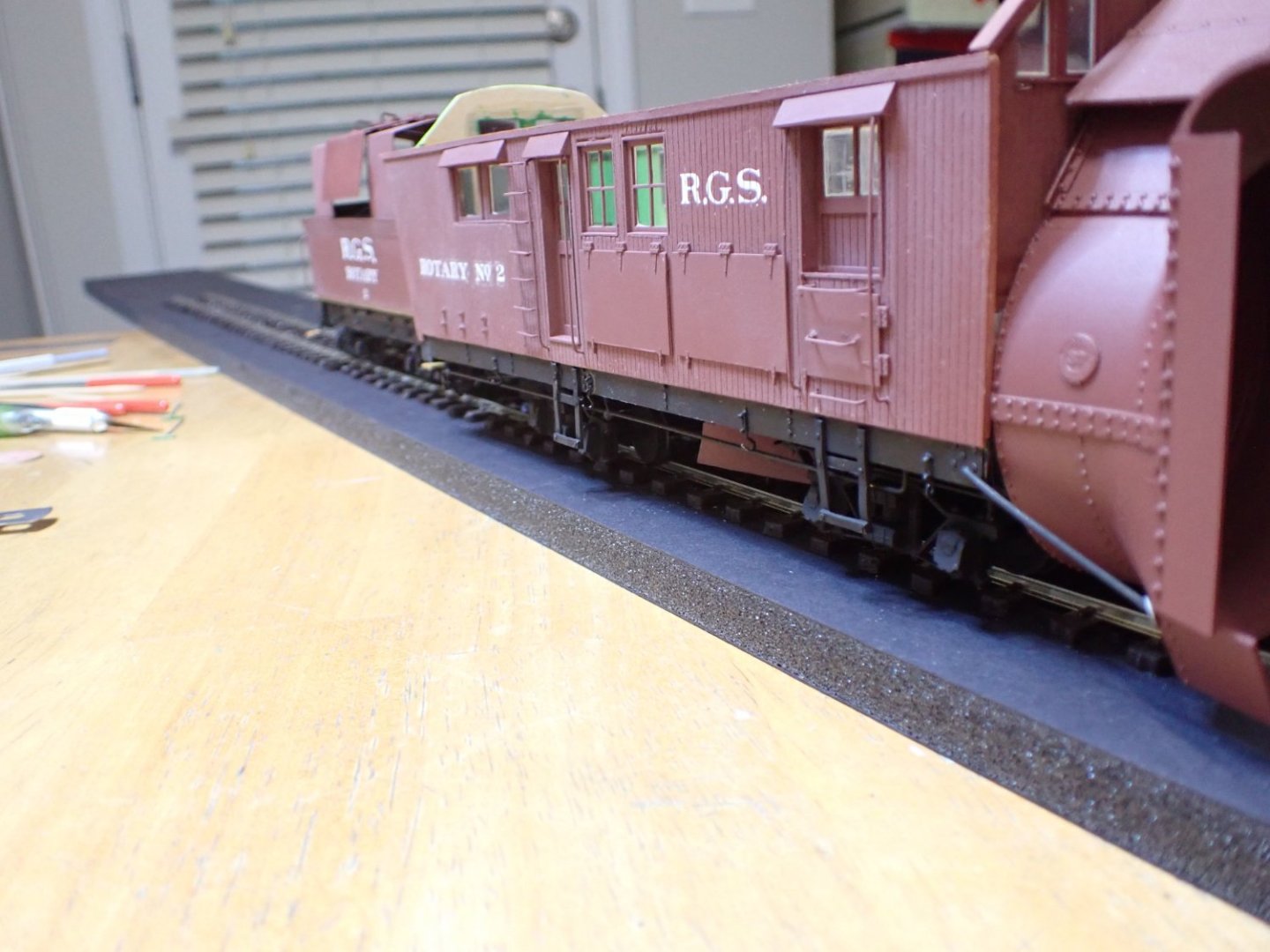
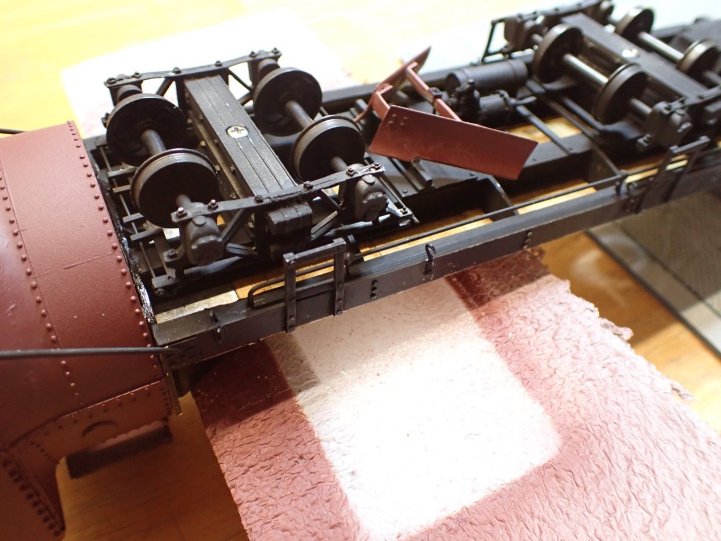
A quick update on the snowplow: The flanger is glued underneath the chassis. These flanger blades could be controlled from the inside of the plow and helped clean-up the track for the rear truck and tender. Now, we are getting serious with the gluing of the right side to the chassis. This is done carefully, making sure everything is aligned in the best possible way. The junction is secured with some strong wood glue (Titebond). That is all for today, folks. Yves
- 102 replies
-
- 12
-
-
-
Bugatti Type 35B by CDW - FINISHED - Italeri - 1:12 Scale
yvesvidal replied to CDW's topic in Non-ship/categorised builds
That is perfect. Thank you. Yves -
Shadow box for model railroad - FINISHED
yvesvidal replied to kgstakes's topic in Non-ship/categorised builds
Lovely layout. Yves -
Stain first. Wipe on Poly will create a plastic film on top of the wood. It may work both ways, but I would stain first. Best, is to try on scrap woods. Yves
- 51 replies
-
- 1
-

-
- Model Shipways
- Baltimore Clipper
- (and 1 more)
-
That is a nice carriage. I don't believe it has been covered before on this forum. Yves
-
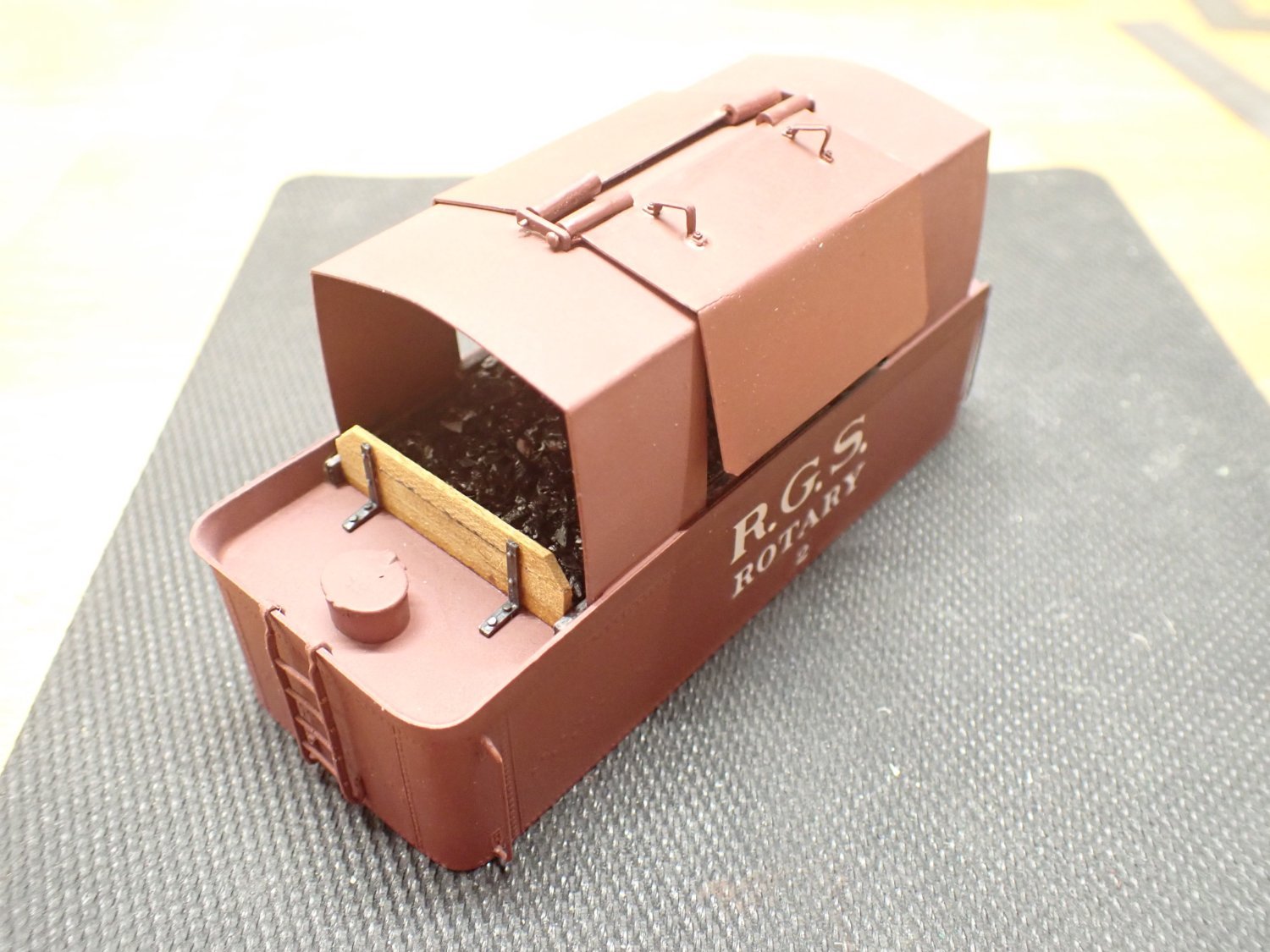
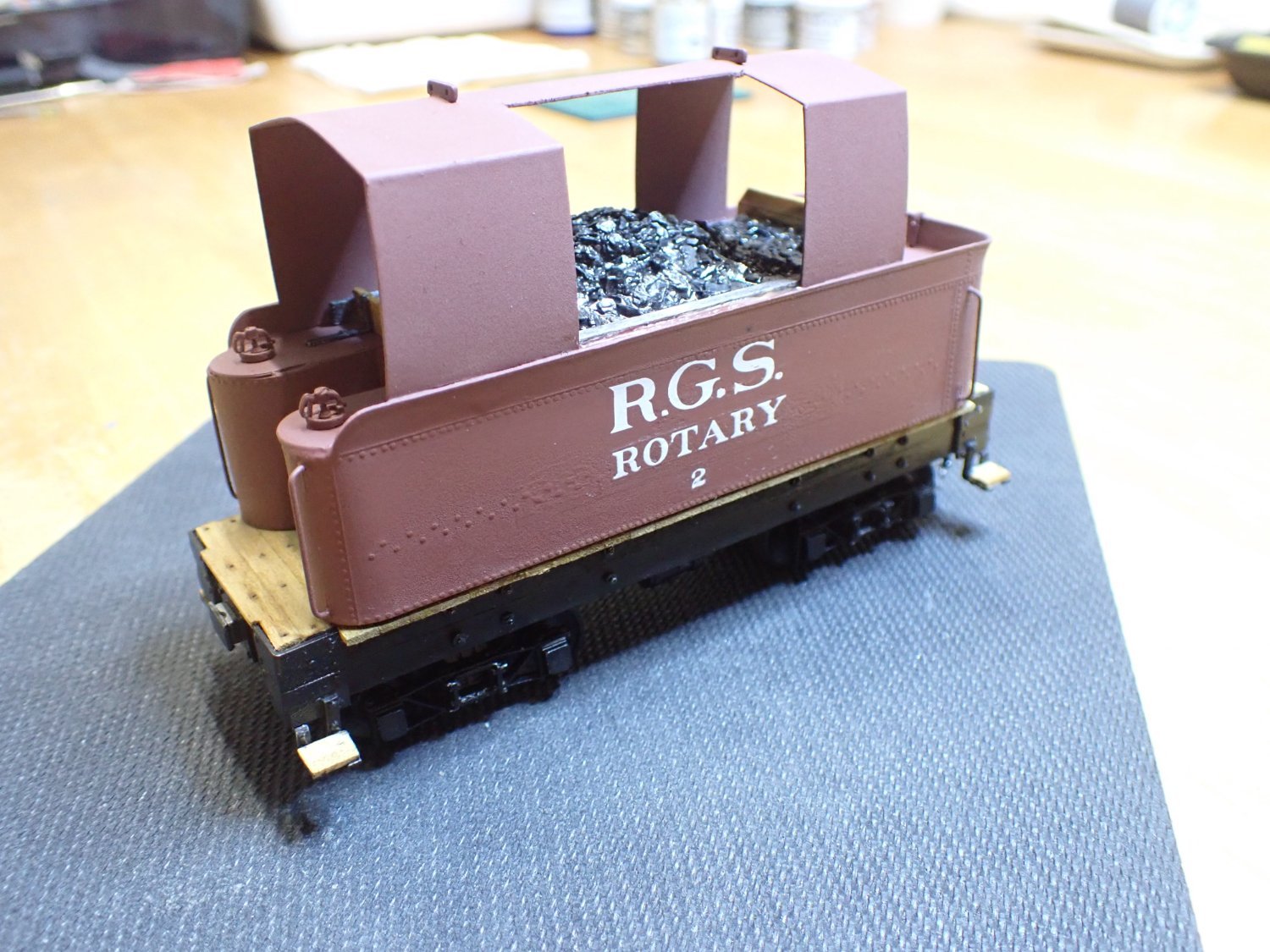
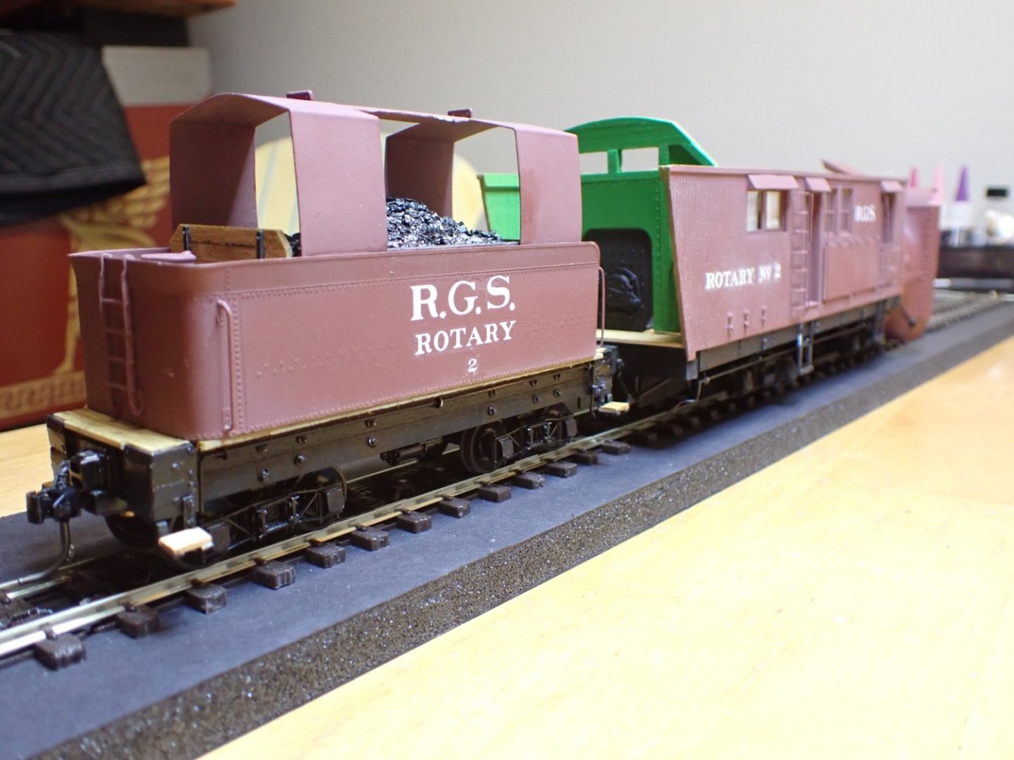
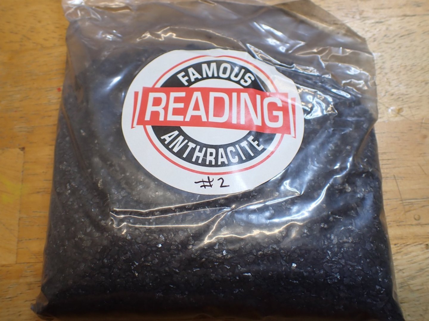
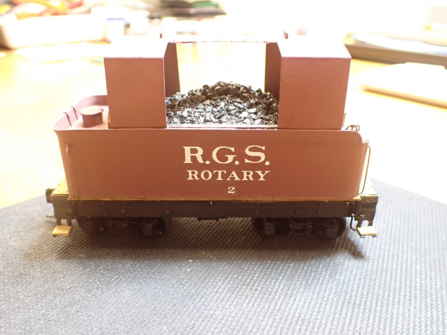
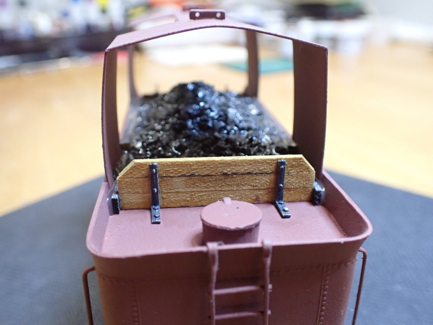
After decaling, it was time to move on with the tender. The box to contain the coal is built with the woods and anchors provided in the kit: The wood is stained to mimic the presence of coal. For the coals, I am using real coal from Reading, crushed at the scale of 1/48th. I usually put some on top of my O scale steam engines, to finish the tenders. This is the real stuff, gathered on the leftovers of the coaling towers of READING. The coal is delicately installed and glued with water diluted PVA glue. And this is where we stand as of today. The tank is not yet glued to the tender chassis: Hope you enjoy that little model. Yves


- 102 replies
-
- 12
-
-
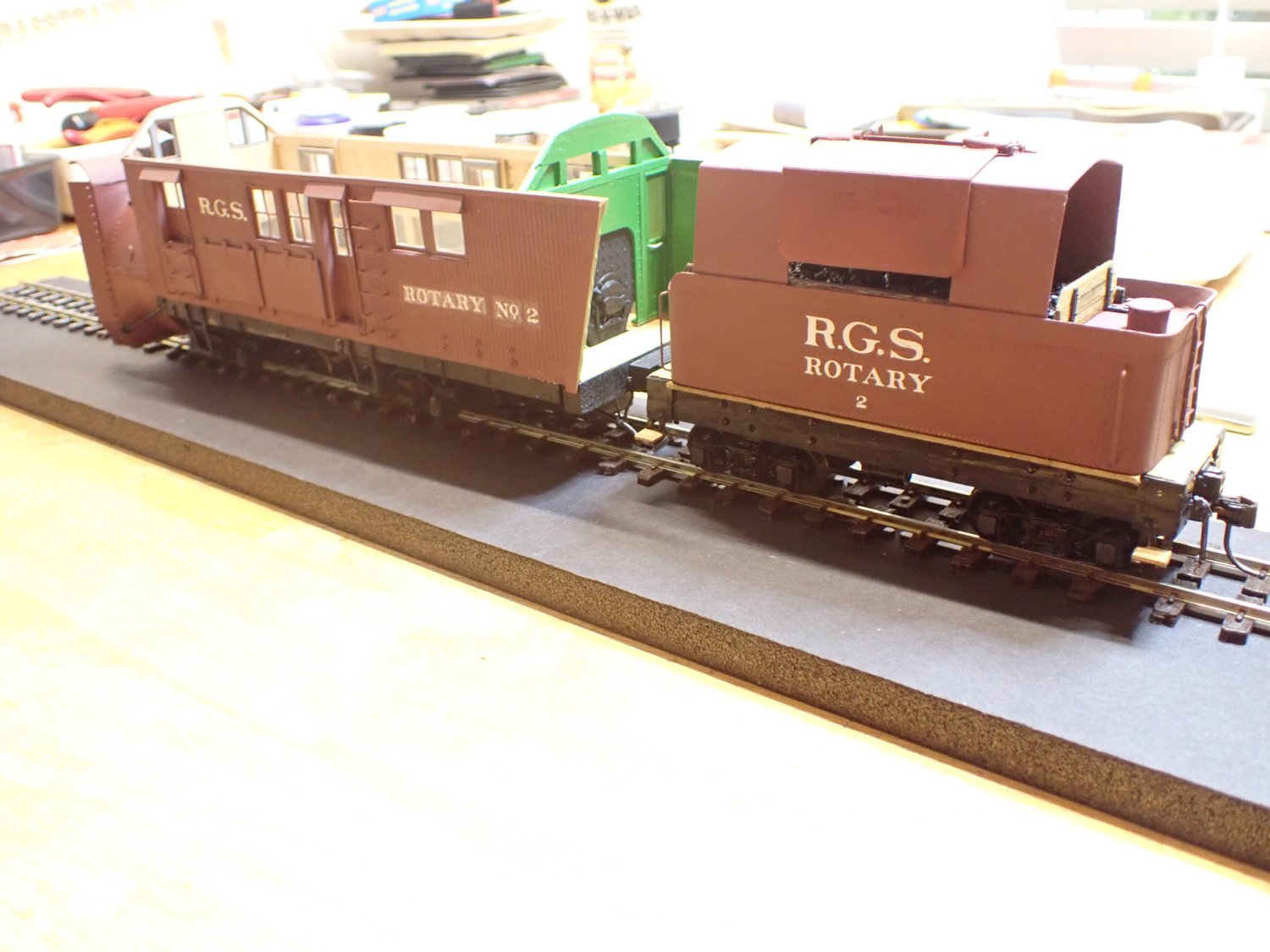
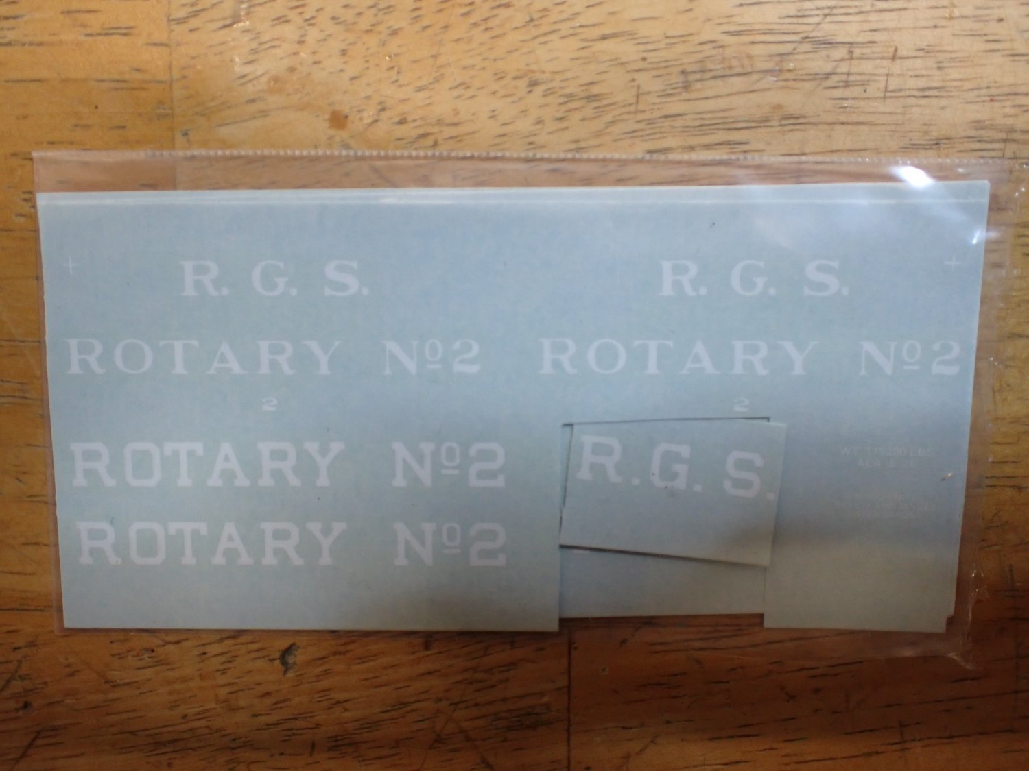
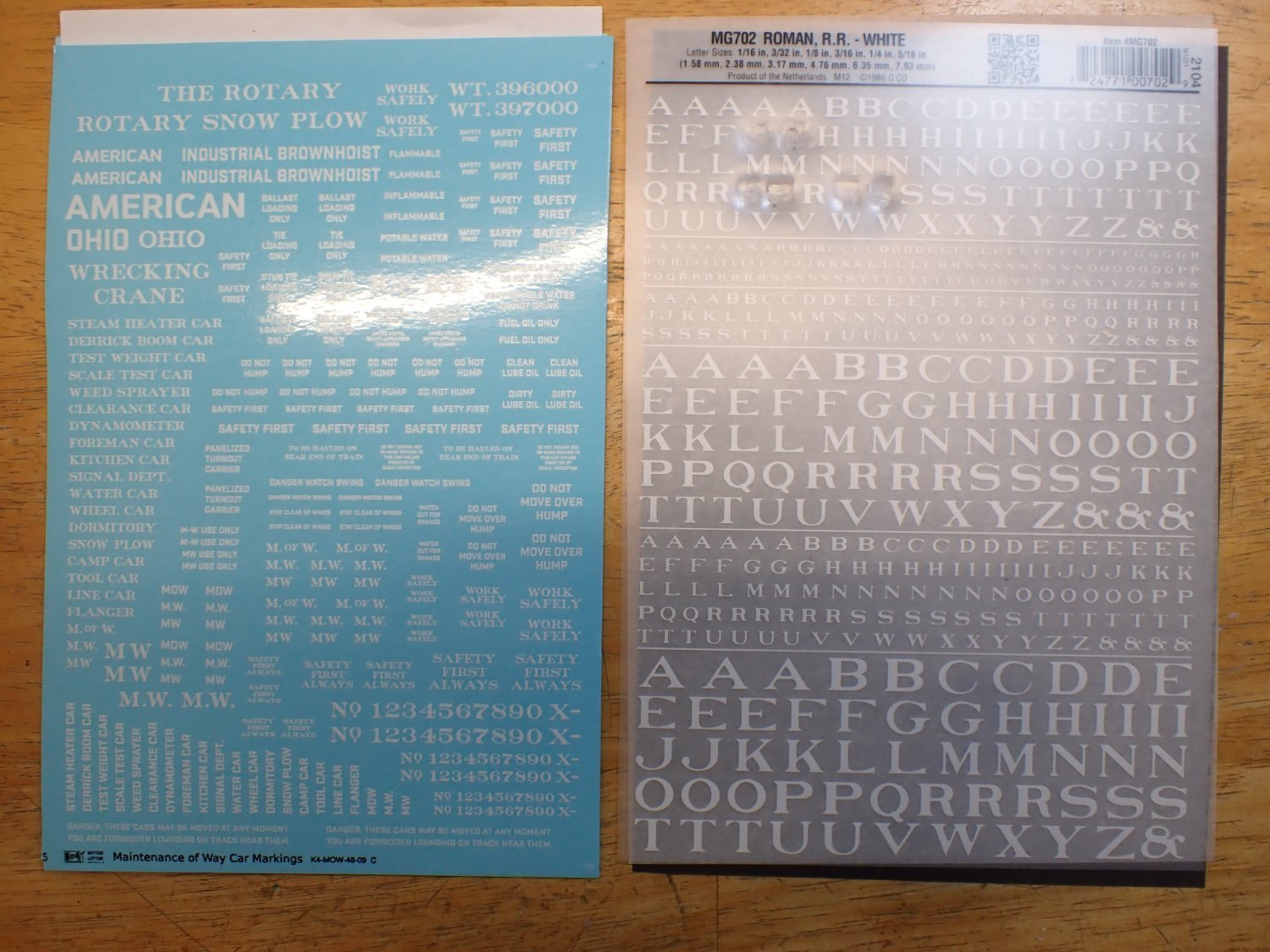
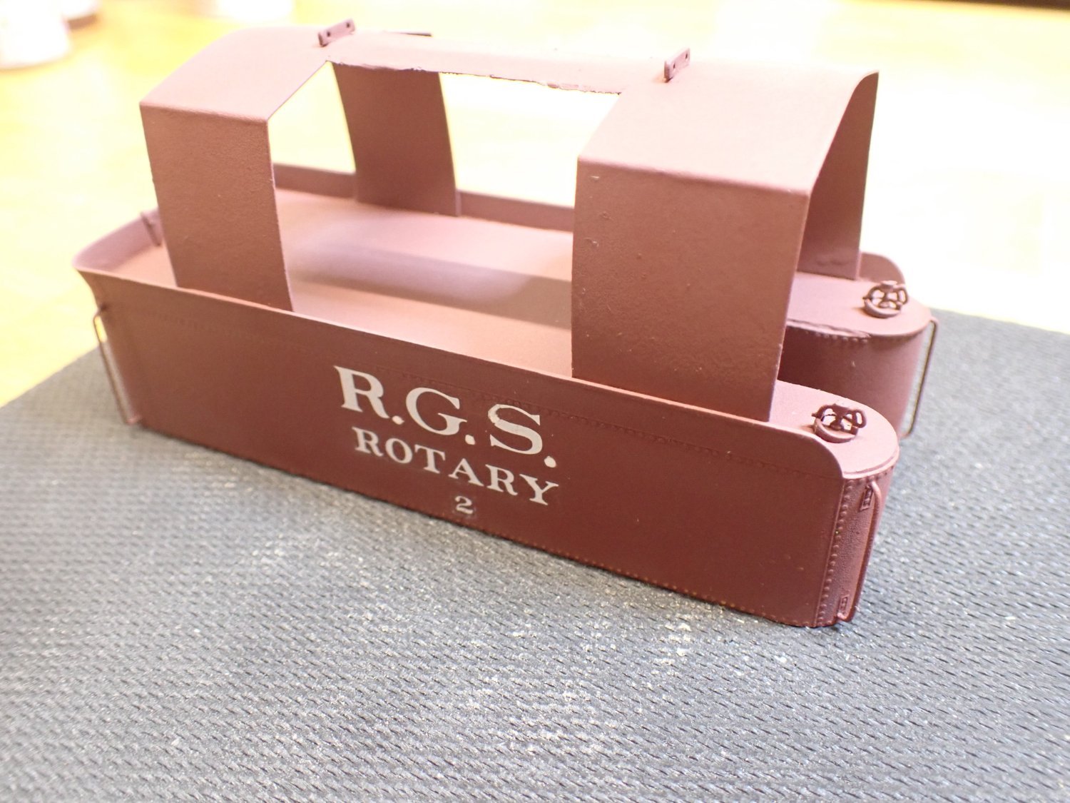
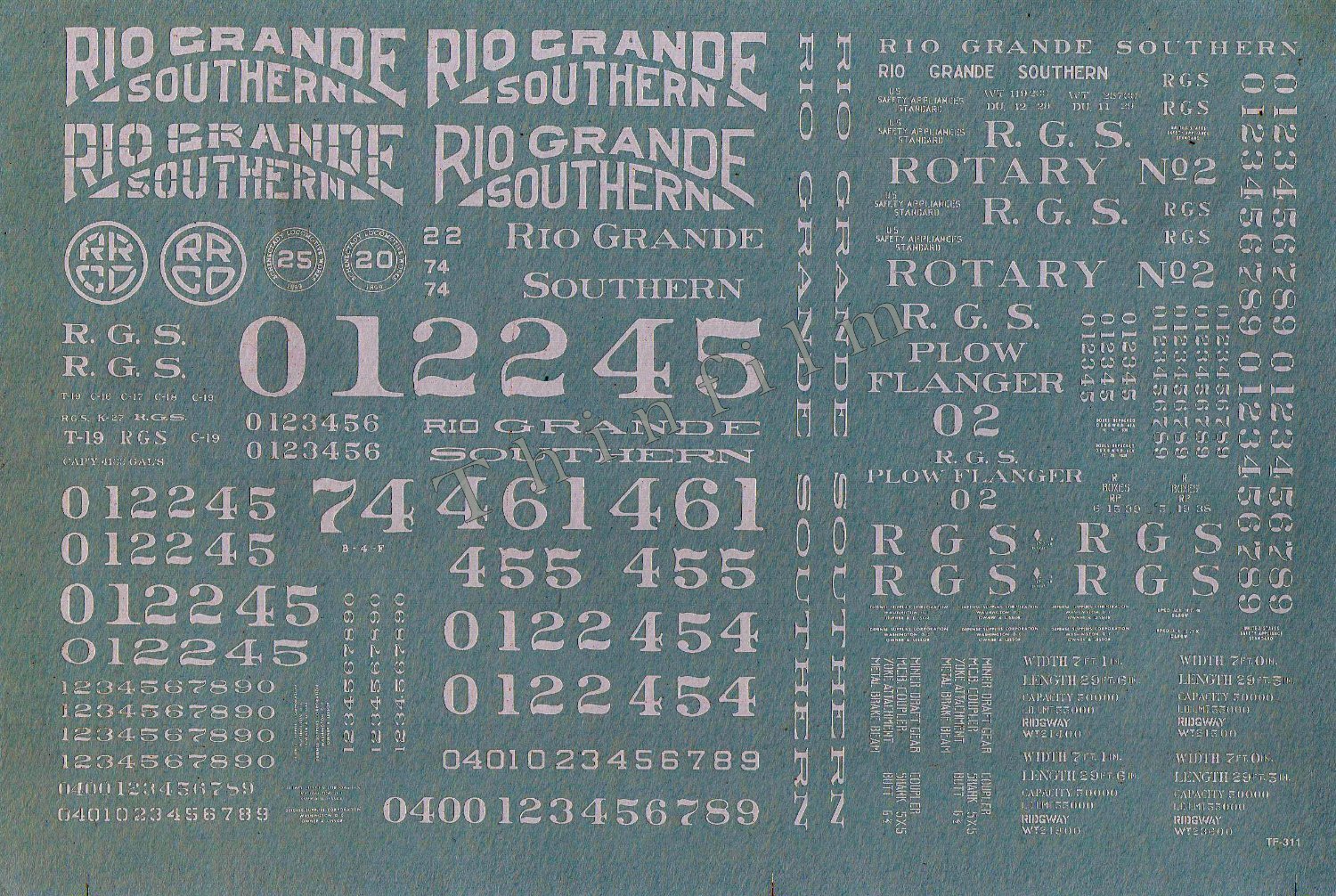
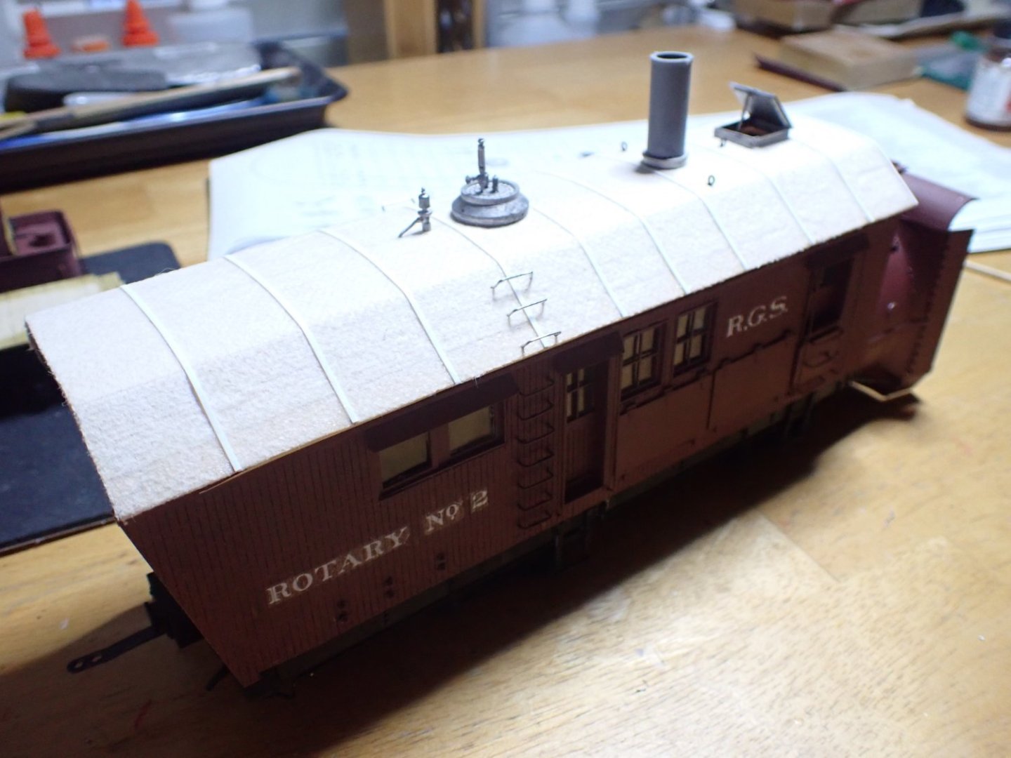
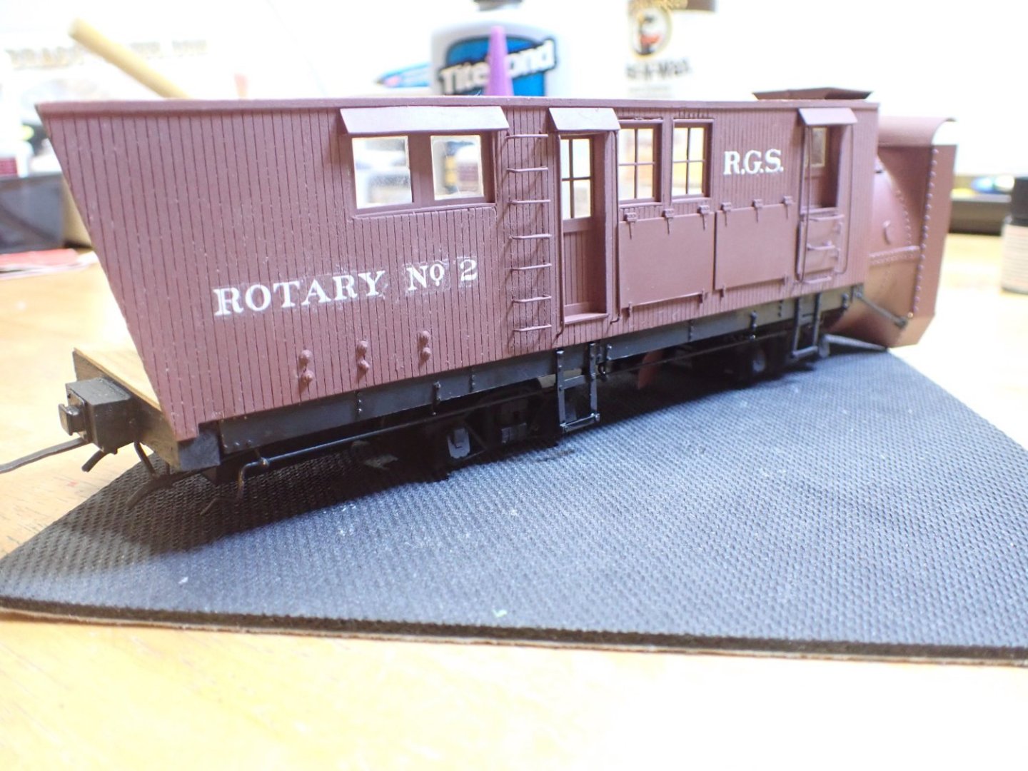
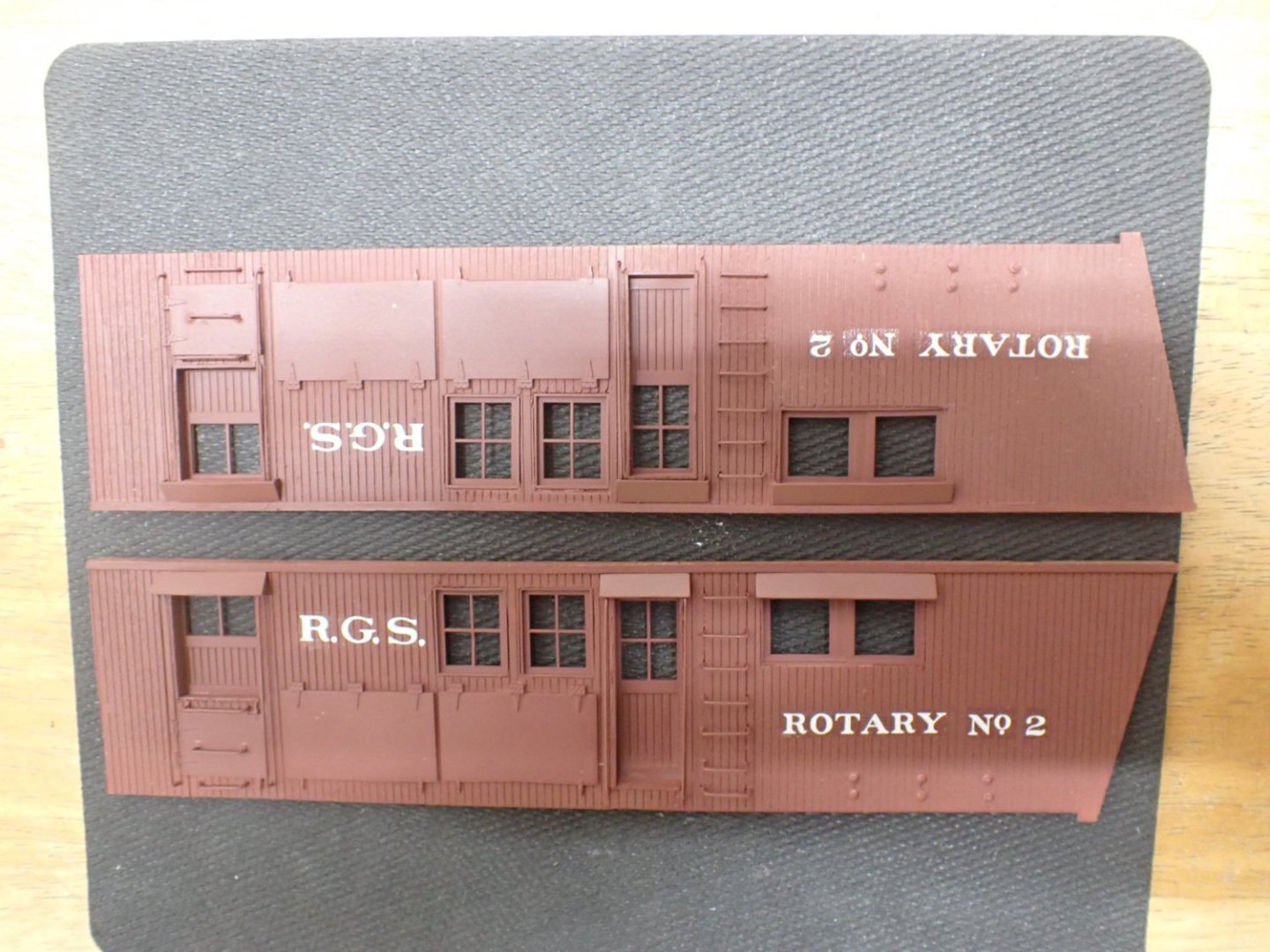
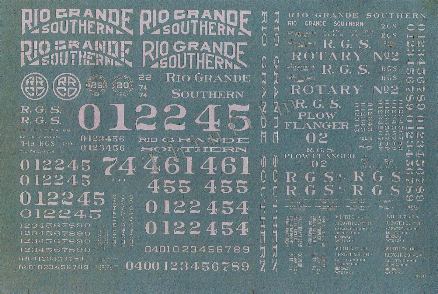
Here comes the dreaded moments (for me): the painting and the decals. The decals are from the early 70's and nothing has been updated or recreated since then: I got in touch with Keith Wiseman, the current manufacturer of that kit (my kit is probably older since it is the original Durango Press) and he sent me some replacement decals. However, he indicated that they are all from the early 70's and as a result they disintegrate as soon as you place them in the water. We are talking of 50 years old decals.... I tried the technique in which you spray matte clear coat on top as an attempt to keep all the pieces together, but I was not very happy with the results. It makes the thickness of the decals too obvious and I ended up sanding everything and re-painting. I decided to go with Dry Transfers that I love. If you have never tried that, it is wonderful and I have used them on a lot of projects. Woodland scenics has a whole series related to railroading and I went with them for the R.G.S. logo. K4, a new comer in the world or Railroad decals, produces a MoW sheet (Maintenance of the Way) that has some "rotary" examples: K4 is very inexpensive (I got 4 sheets for $15, including shipping) whereas Woodland Scenics is overpriced ($19 for one sheet, including shipping). By combining these two sets, I was able to come up with something that looks prototypical: You can clearly see the crispness of the transfers which do not have the film, around the letters. Not shown on that picture, I used a sharp blade and cut decals and transfers, following the wood planks for added realism. It was relatively expensive to decals that tender and snowplow and Keith Wiseman indicated to me, but a little bit too late, that Thinfilm Decals has these decals ready to go, for On3 rotary snowplow operated by the Rio Grande Southern. Oh well too late.... I did not have the heart to sand everything and repaint a third time. Yves


- 102 replies
-
- 11
-
-
-
I love these fat and beefy planes. YVes
-
Bugatti Type 35B by CDW - FINISHED - Italeri - 1:12 Scale
yvesvidal replied to CDW's topic in Non-ship/categorised builds
Craig, you need to fabricate some 1/12th scale sawhorses to present your beautiful model. Resting that body on three paint jars is not serious :-) Yves -
So, the Bismarck had an aluminum top which was not painted? That is something I did not know and which is rarely recreated on models. Fantastic work Madtatt. Yves
-
I like the second hull much better. This is going to be a little jewel at the 1/48th scale. Yves
- 128 replies
-
- 2
-
-
- zulu
- sternwheeler
- (and 1 more)