yvesvidal
-
Posts
3,634 -
Joined
-
Last visited
Content Type
Profiles
Forums
Gallery
Events
Everything posted by yvesvidal
-
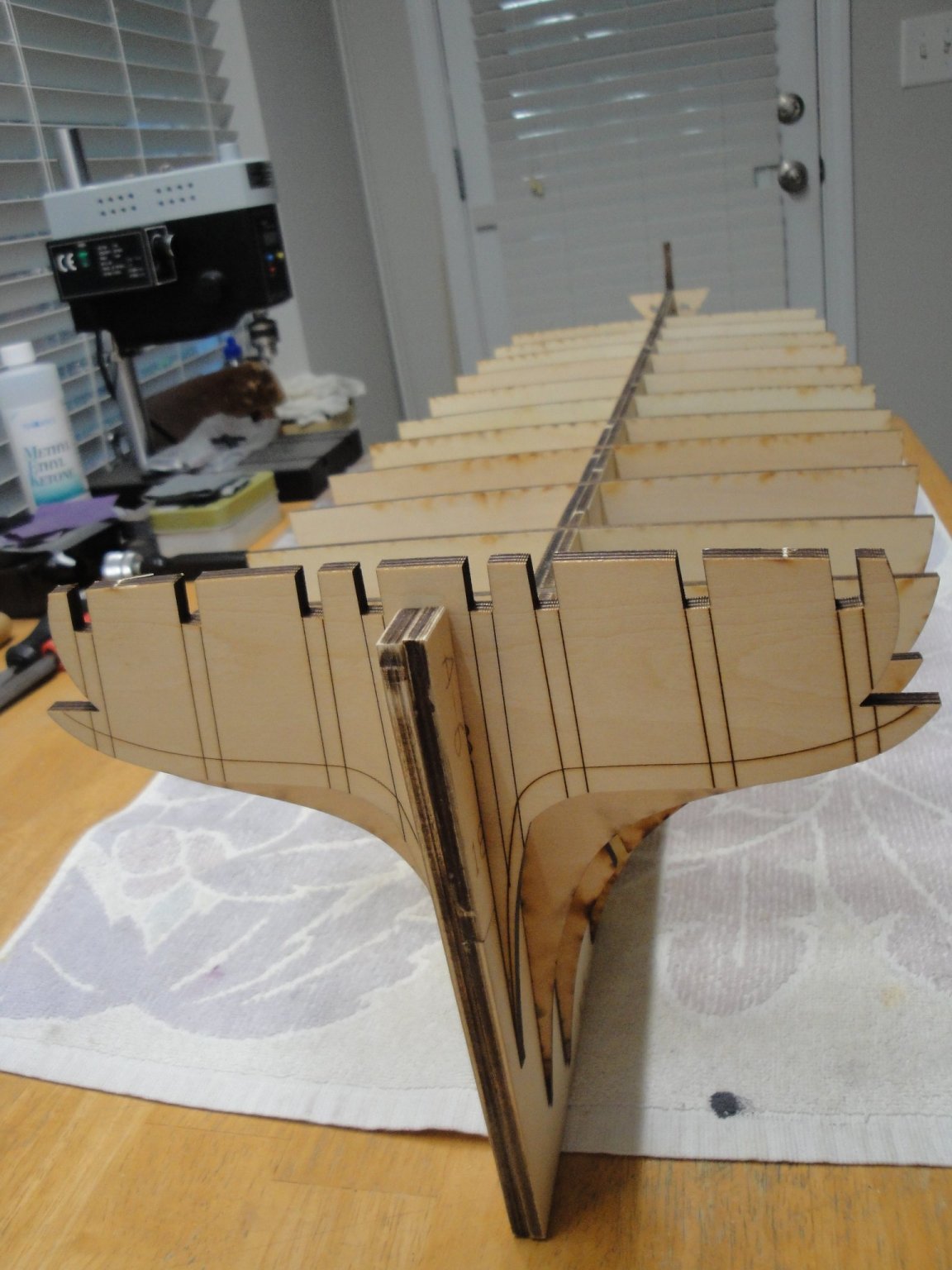
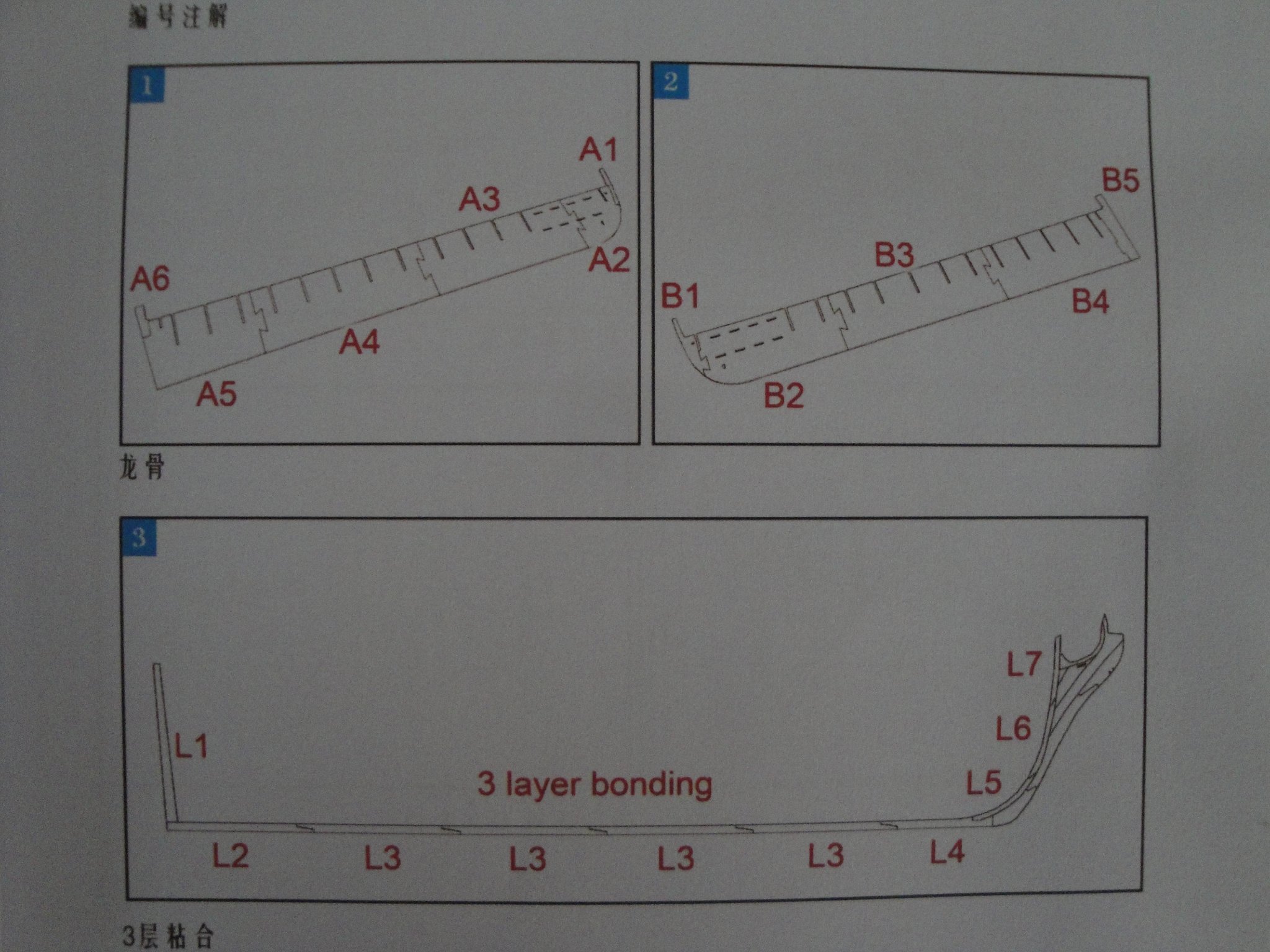
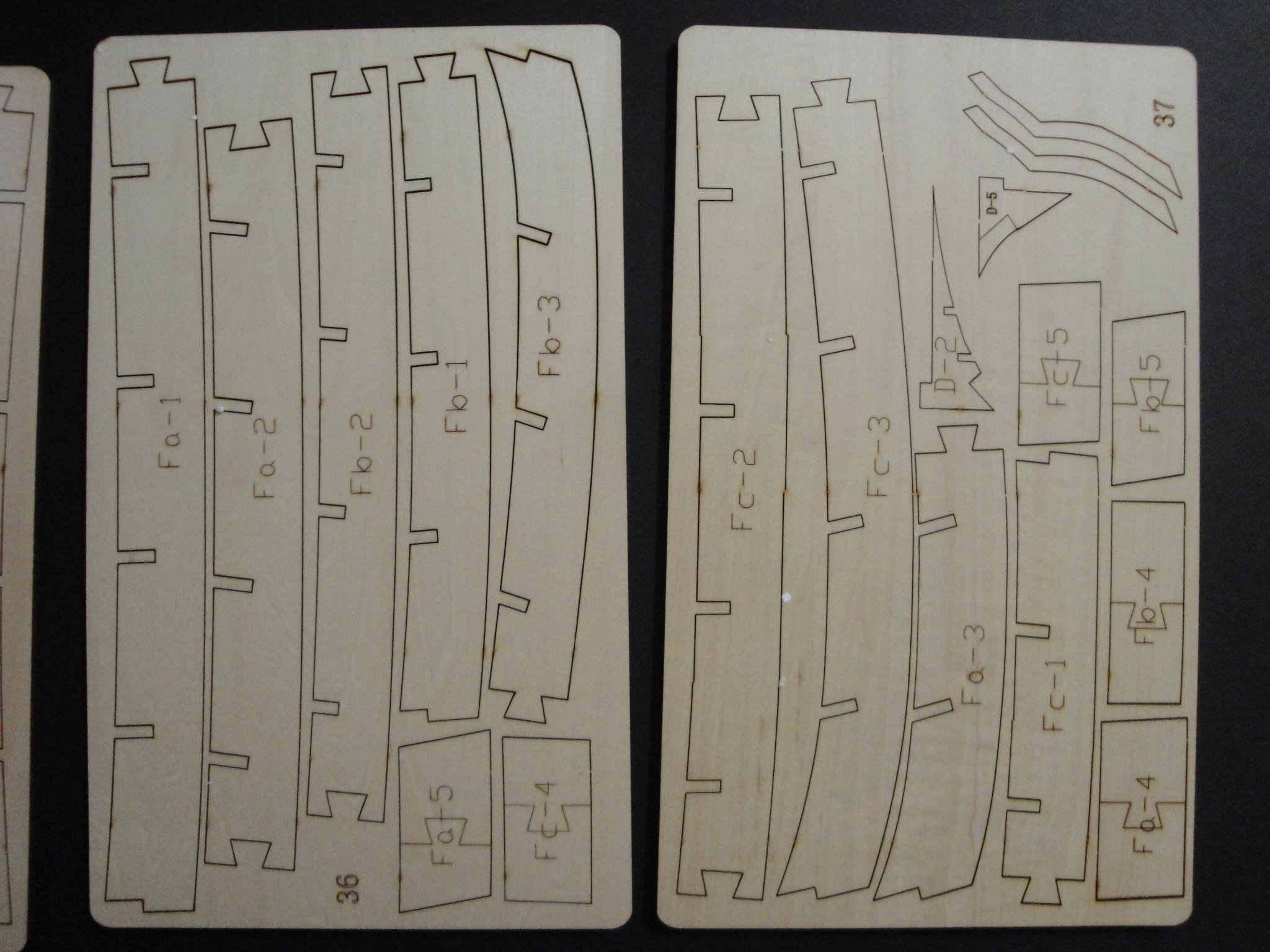
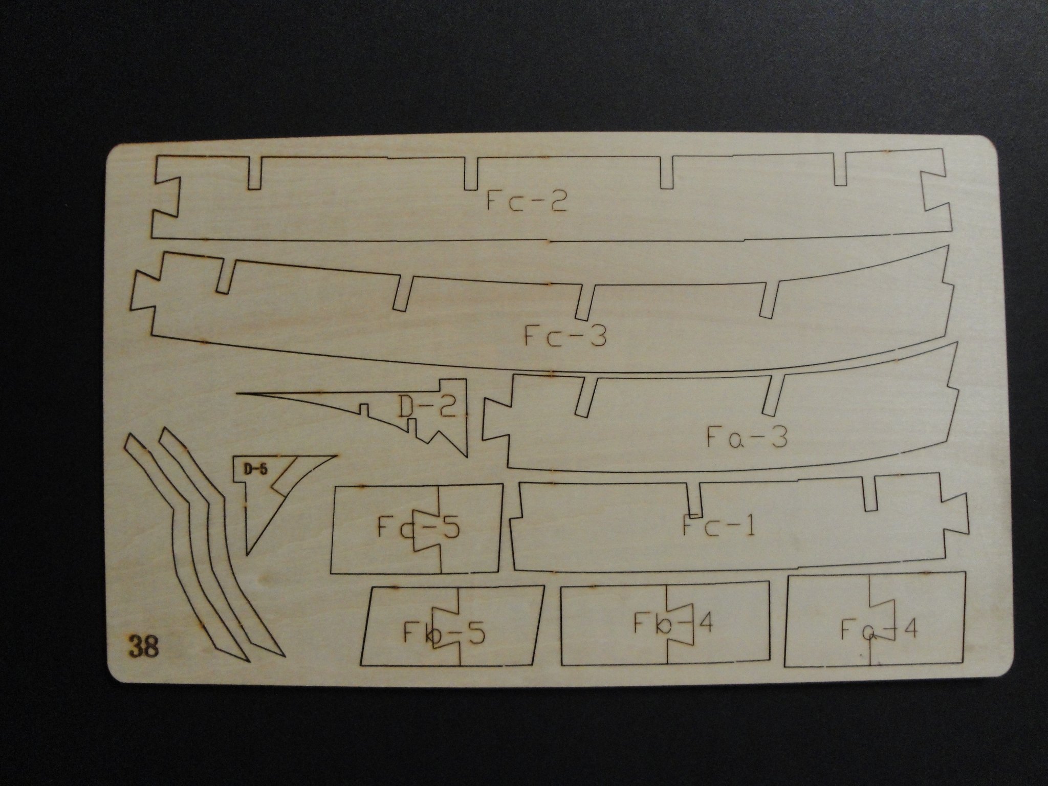
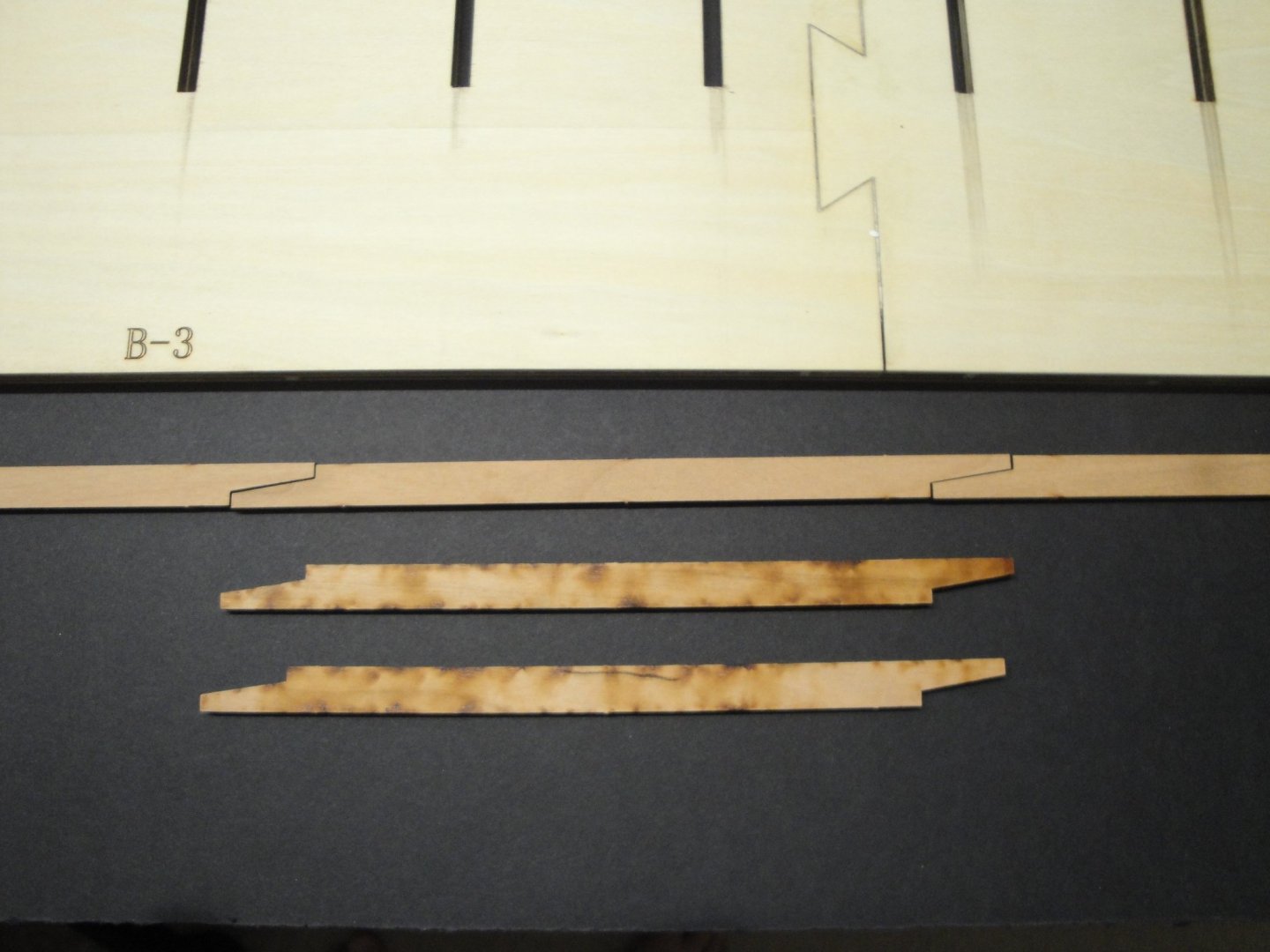
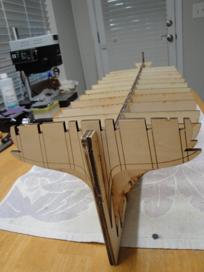
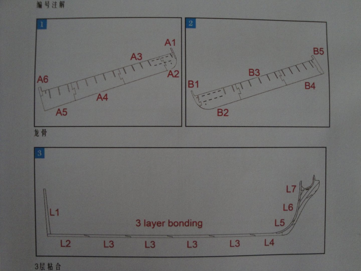
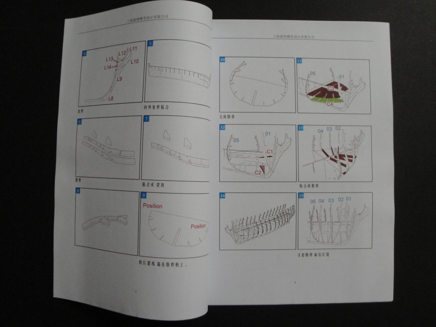
 Looking at the keel and pondering: The keel is made up of three layers of the exact same parts. What you see on the picture (above) is one layer only and the main spine. The spine is 10 mm thick and the three layers of cherry wood making up the keel, will be about 12 mm. That creates a rabbet of 1 mm deep on each side, which should be enough. What I do not like is the fact that the parts are not staggered, for solidity and straightness. I am thinking about cutting the first part (L4 on the instructions) shorter and staggering at least the middle section of the three layers sandwich. Cutting it short by an inch or two, would automatically create an offset that will force the flat and straight L3 parts to be staggered. The stern L2 can also go through the same treatment. To build that keel, you have to secure both sides with straight guides and glue all these small parts within the trough created by the guides. Hopefully the result will be straight and the staggering can only help. I just wish CAF had thought about this possible improvement. Yves
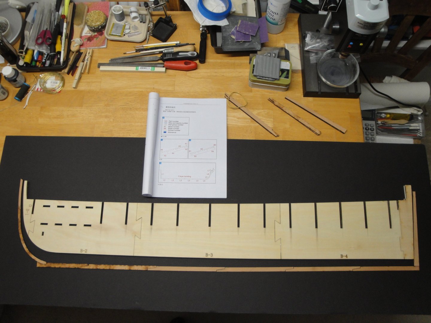
-
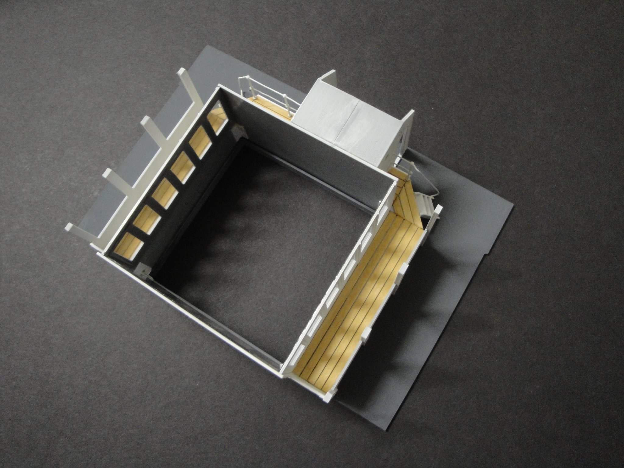
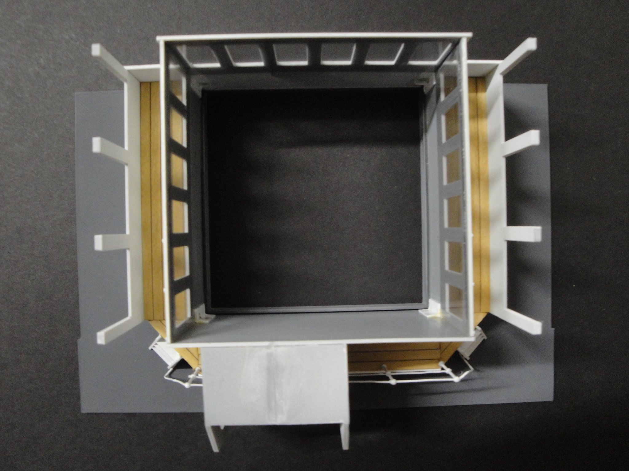
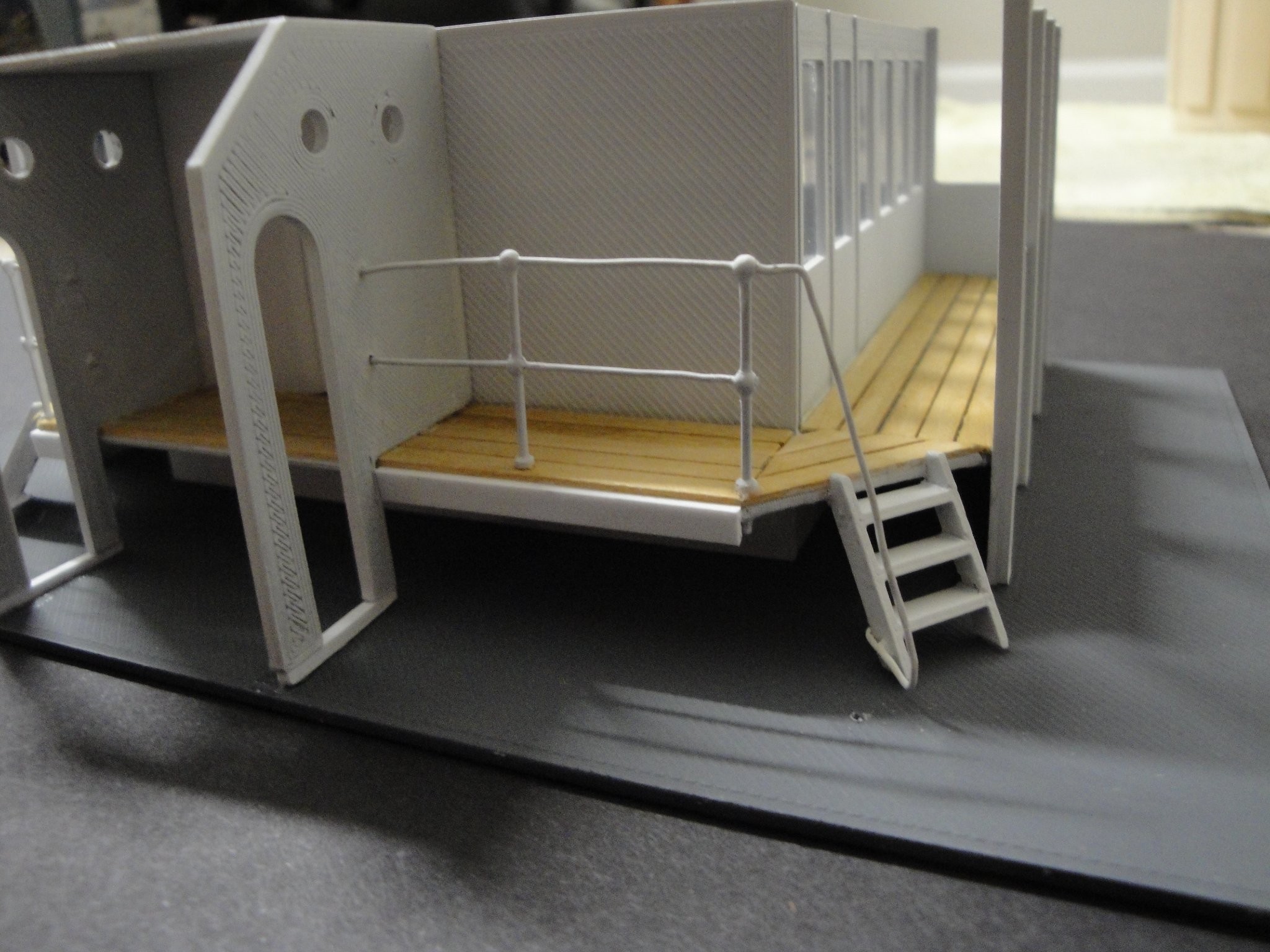
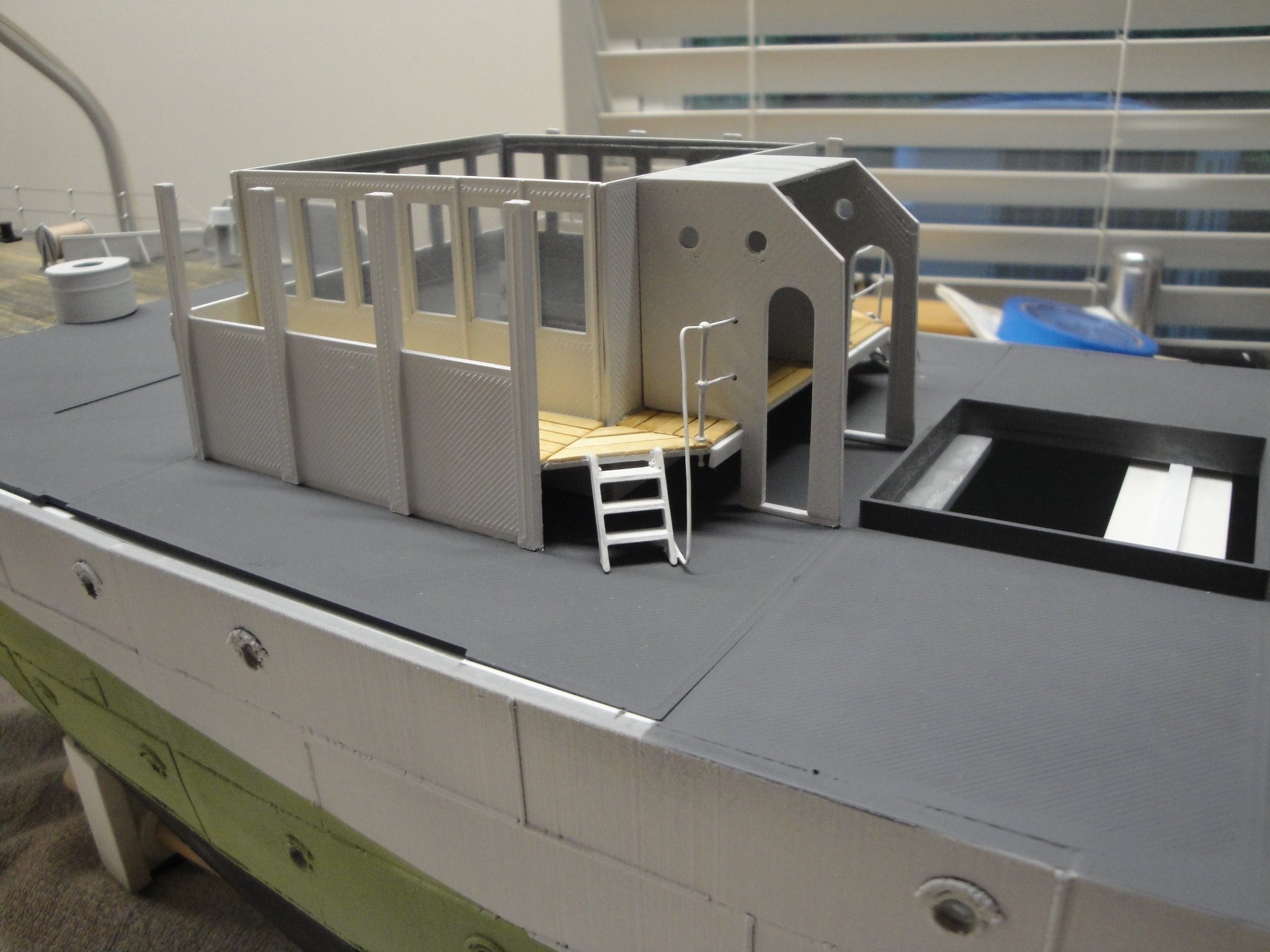
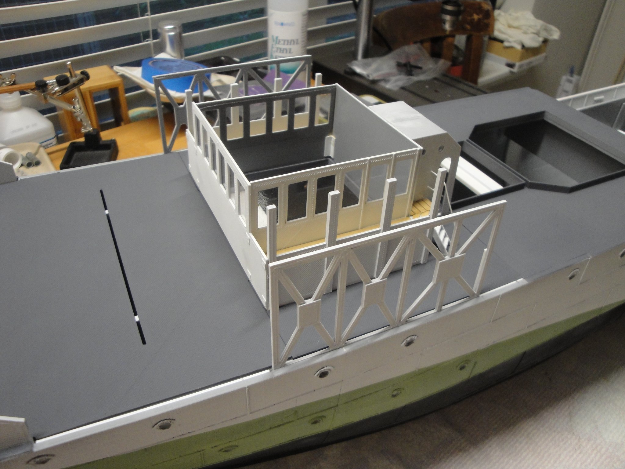
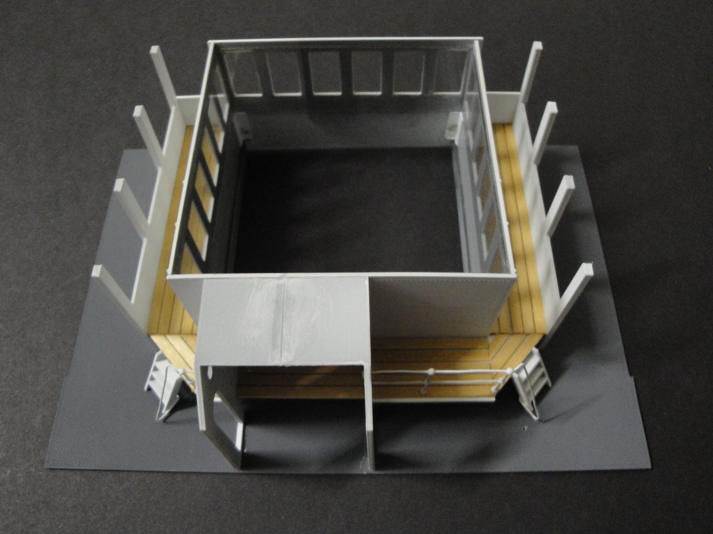
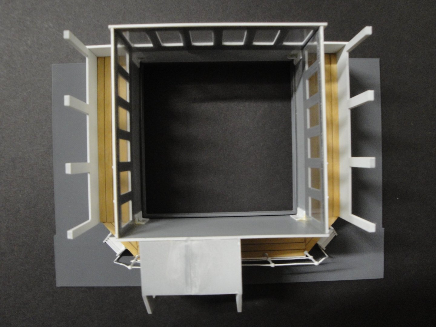
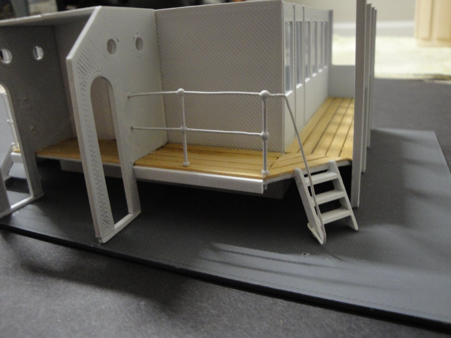
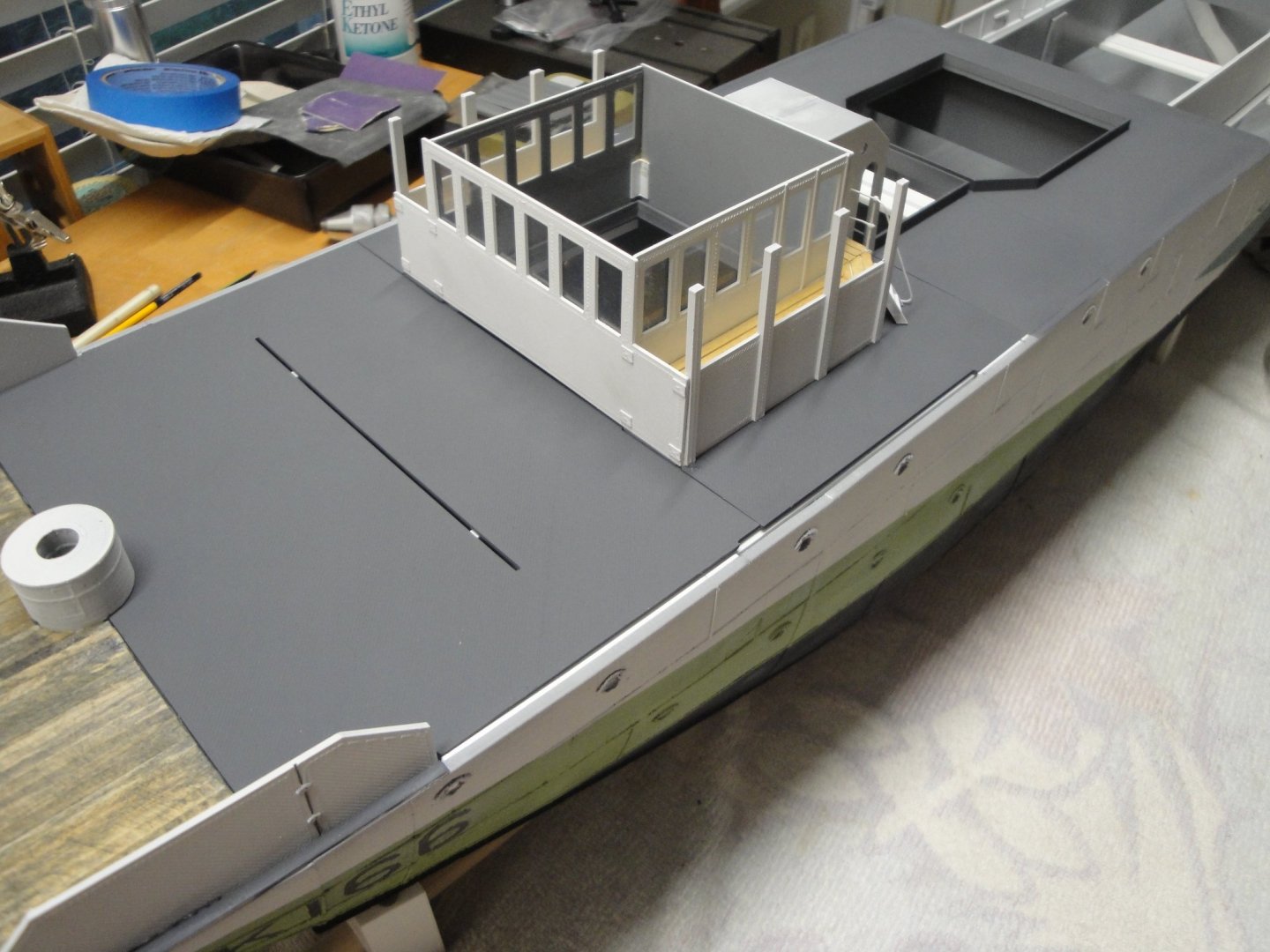
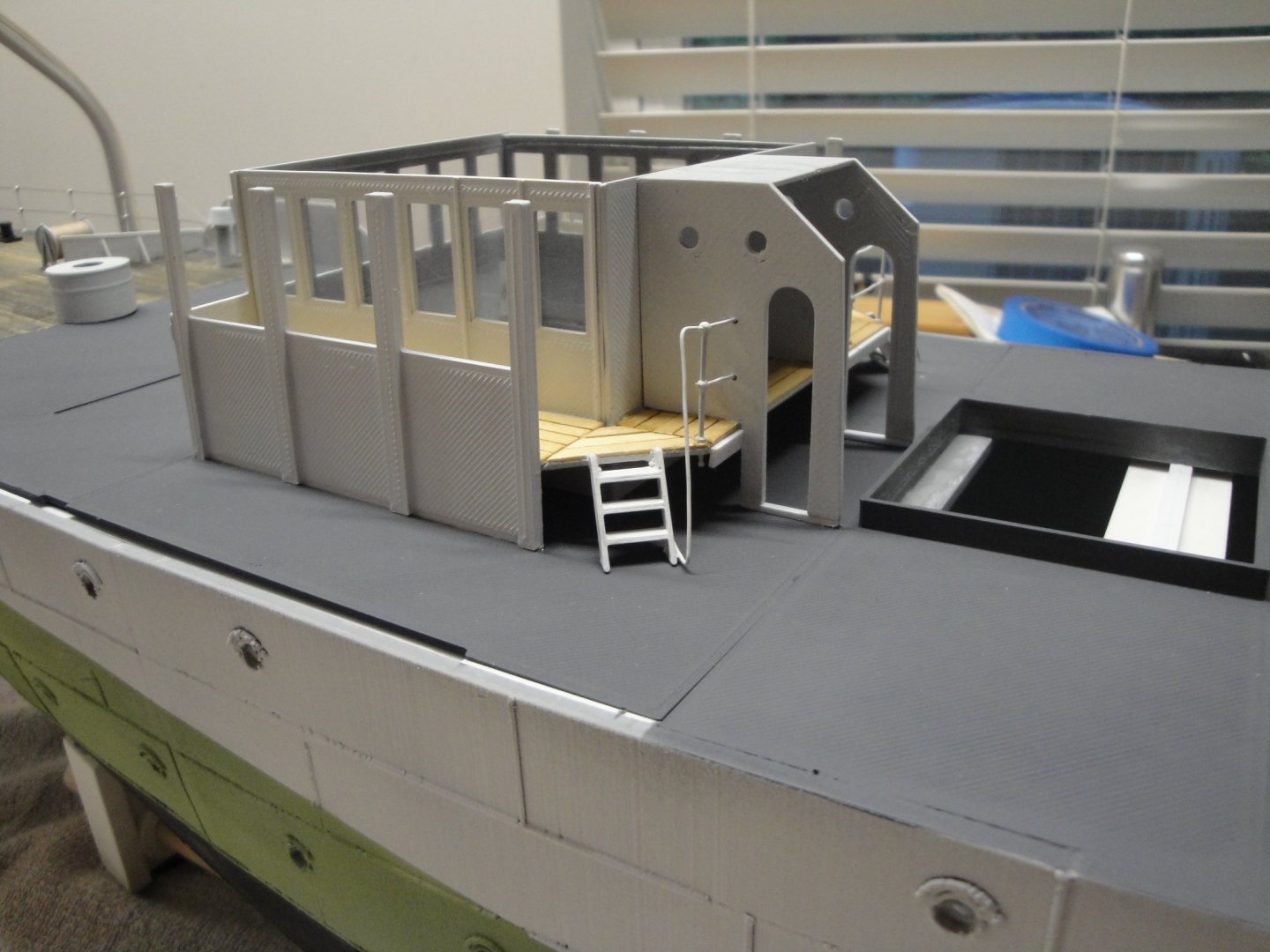
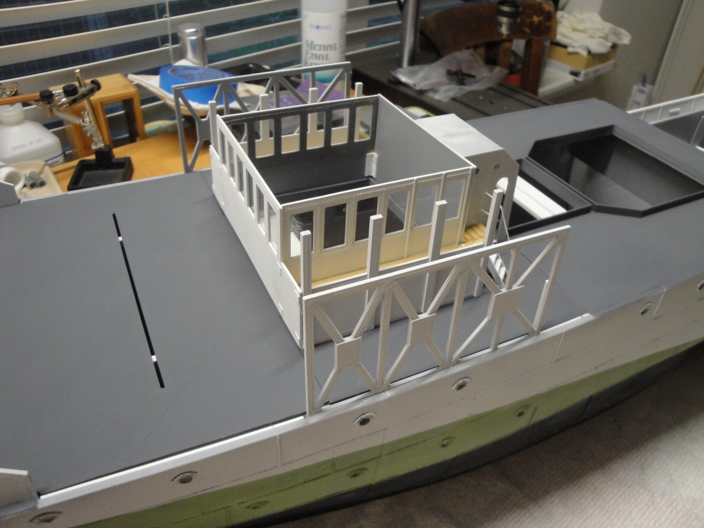
MODULE #3a - The Wheel House As promised, here are a few pictures of the Wheel house, located on Module #3a. I have decided to not depict the inside of it, first because I am not sure how it was done and secondly for the simple reason that it will be almost impossible to look into it. The Virtual kit provides all the parts that you see here. The only additions are: - 3 stanchions (Caldercraft 20 mm) - Thin plexiglass to simulate the glass - 1/32th x 1/8th inch basswood strips - 0.6 mm brass wire for the railing. - four tiny piece of right angle styrene strips to hold the walls. In situ.... Module #3a cannot be glued to the hull yet, as Module #2 must be "inserted" first. It will be kept aside for now. Yves

- 321 replies
-
- 14
-

-
- Finished
- Flower-class
- (and 1 more)
-
Lancia Assunta by maurino
yvesvidal replied to maurino's topic in - Build logs for subjects built 1901 - Present Day
Superb little boat Maurino. It is like walking back along the shores of the Mediterranean sea, from the Spanish Costa Brava, all the way to Genoa, where you can admire these colorful fishing boats. The fish is always fresh and so delicious, thanks to the work of these fishermen and wonderful boats. What will be your next project? Yves -
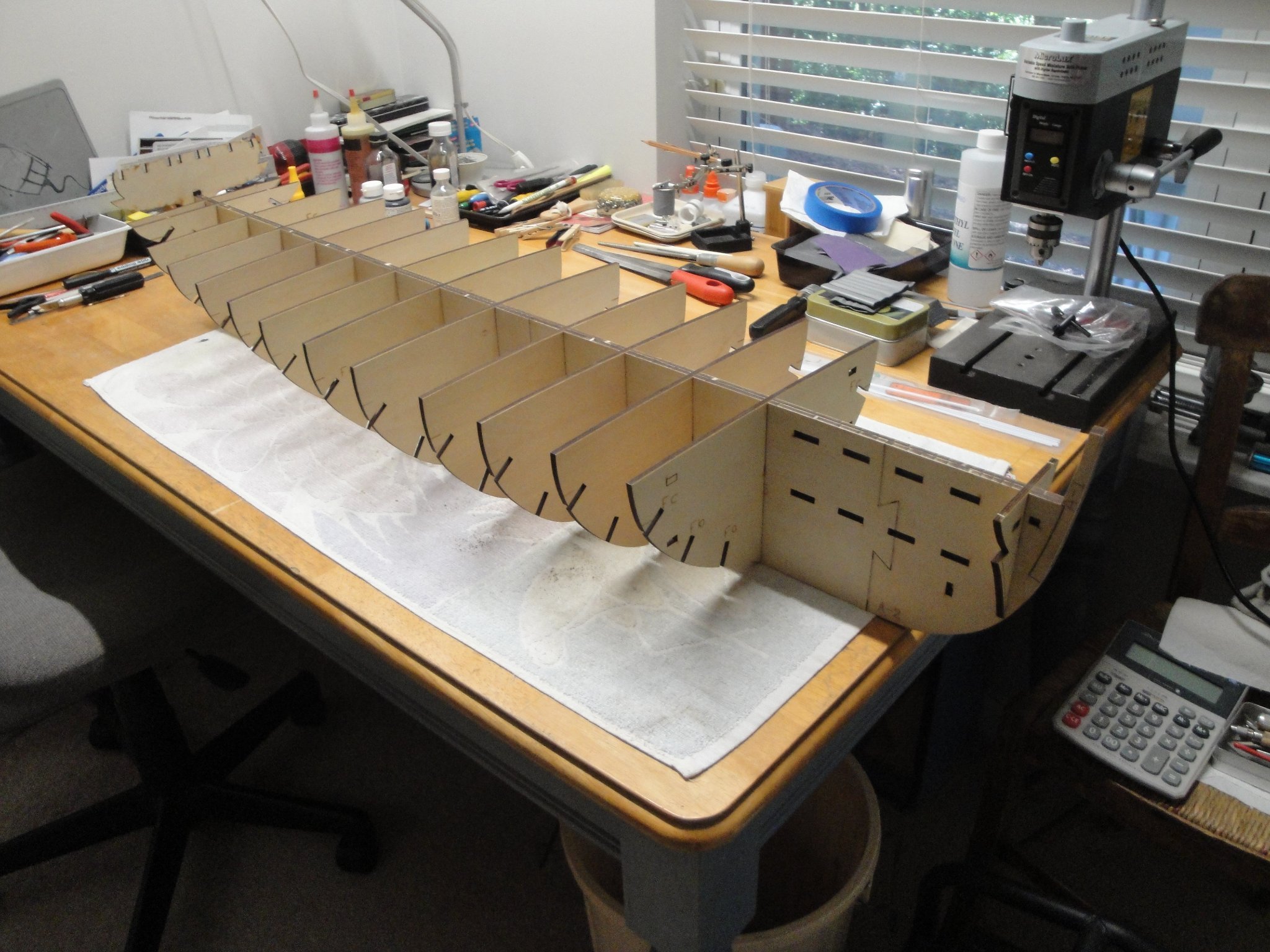
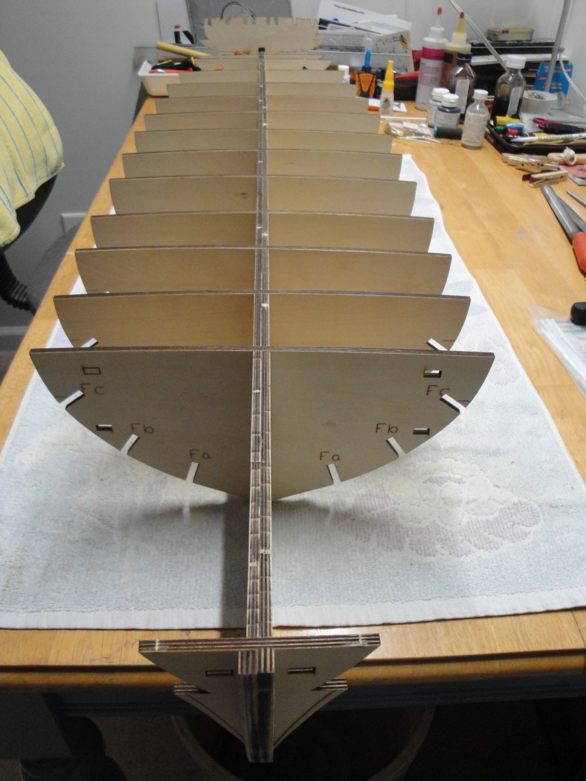
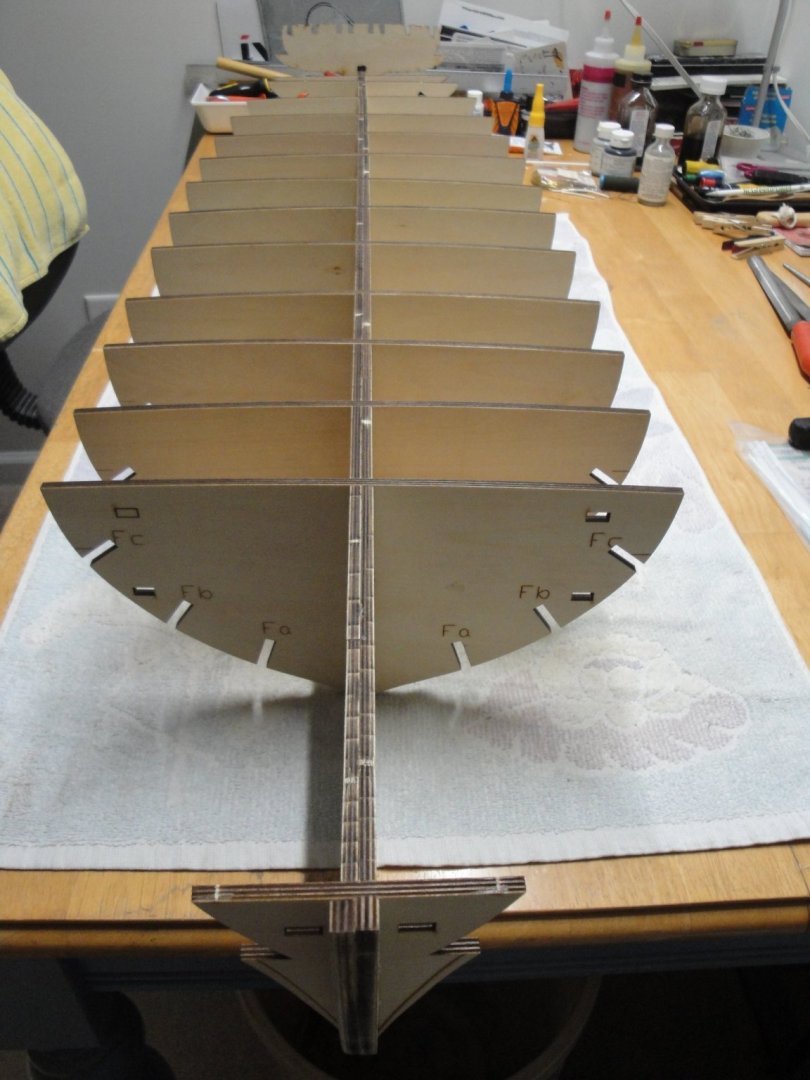
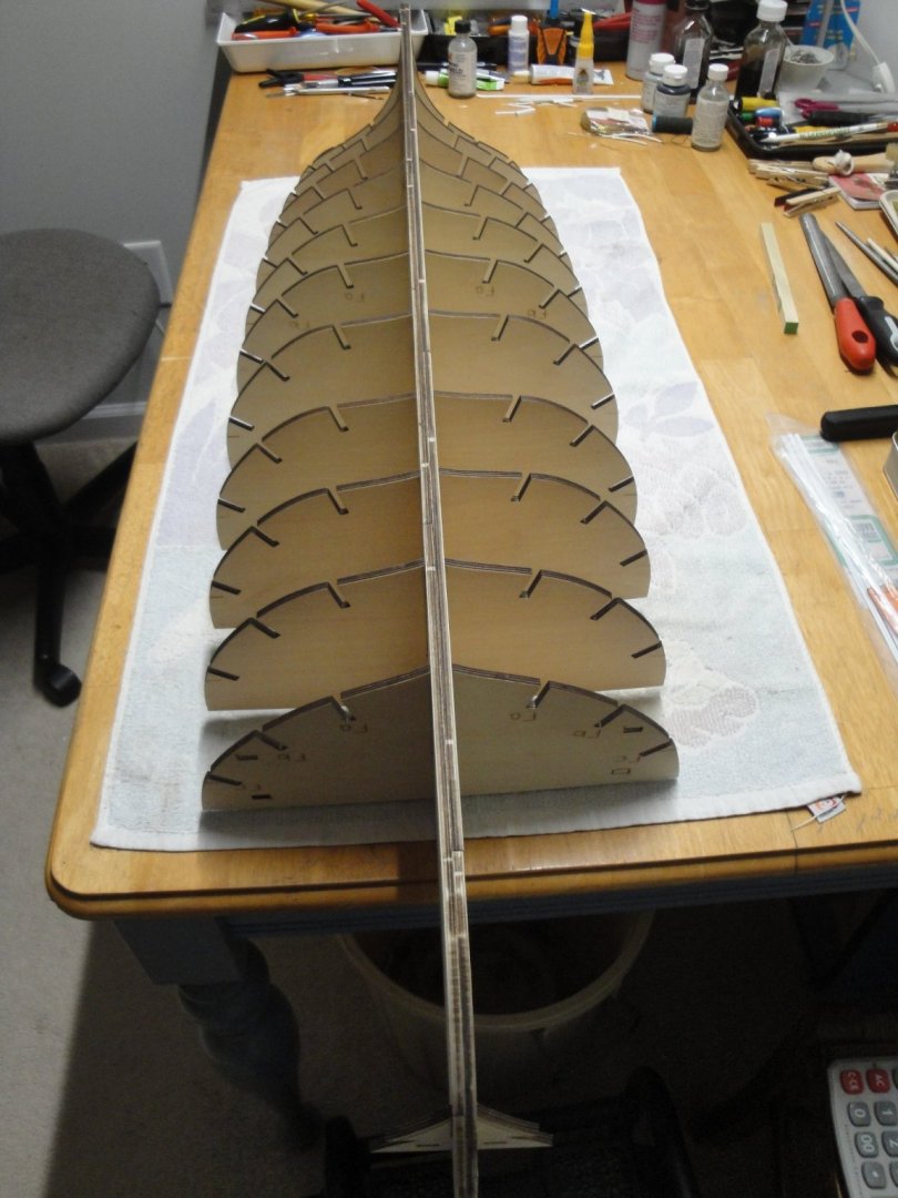
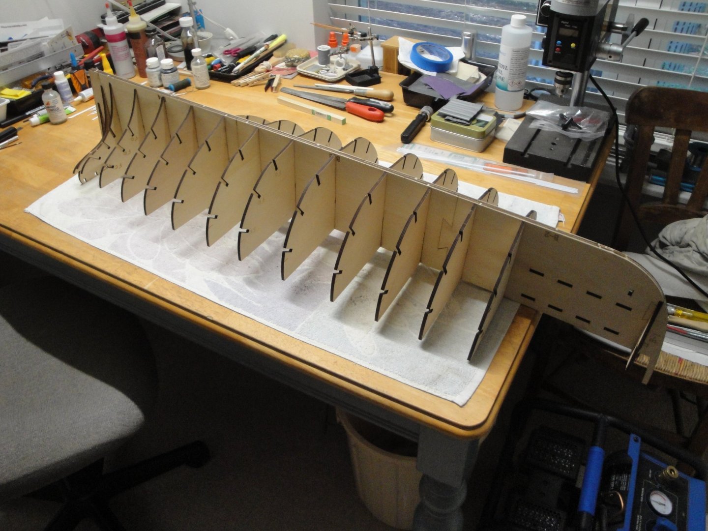
I just decided to see how the bulkheads fit on the spine: Perfectly !!! You barely have to remove some charring on the spine and the bulkhead will slide in and be perfectly square and flush. I am truly impressed by the quality of the cuts and fit. On such a large model, it is impressive: Hmm... I thin Bulkhead #18, needs to sit lower. I misplaced it. The keel is built separately and then glued to the spine. The keel is made of three layers of cherry wood. Yves

- 507 replies
-
- 17
-
-

-
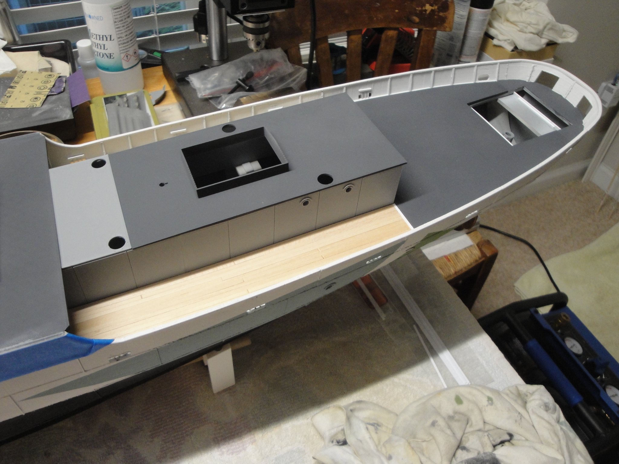
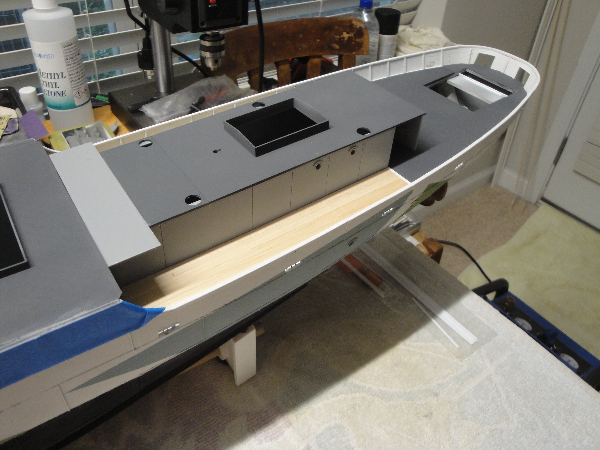
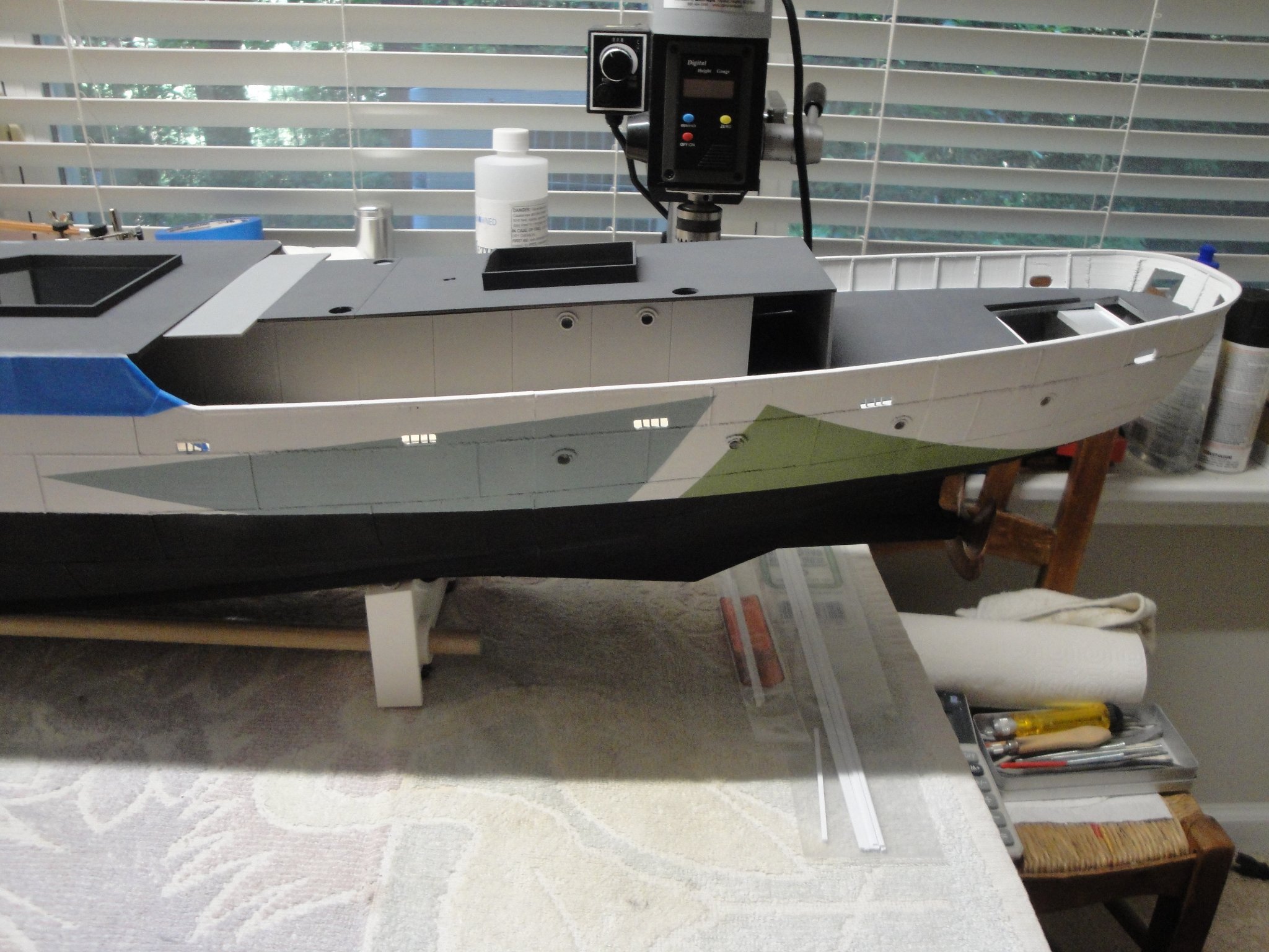
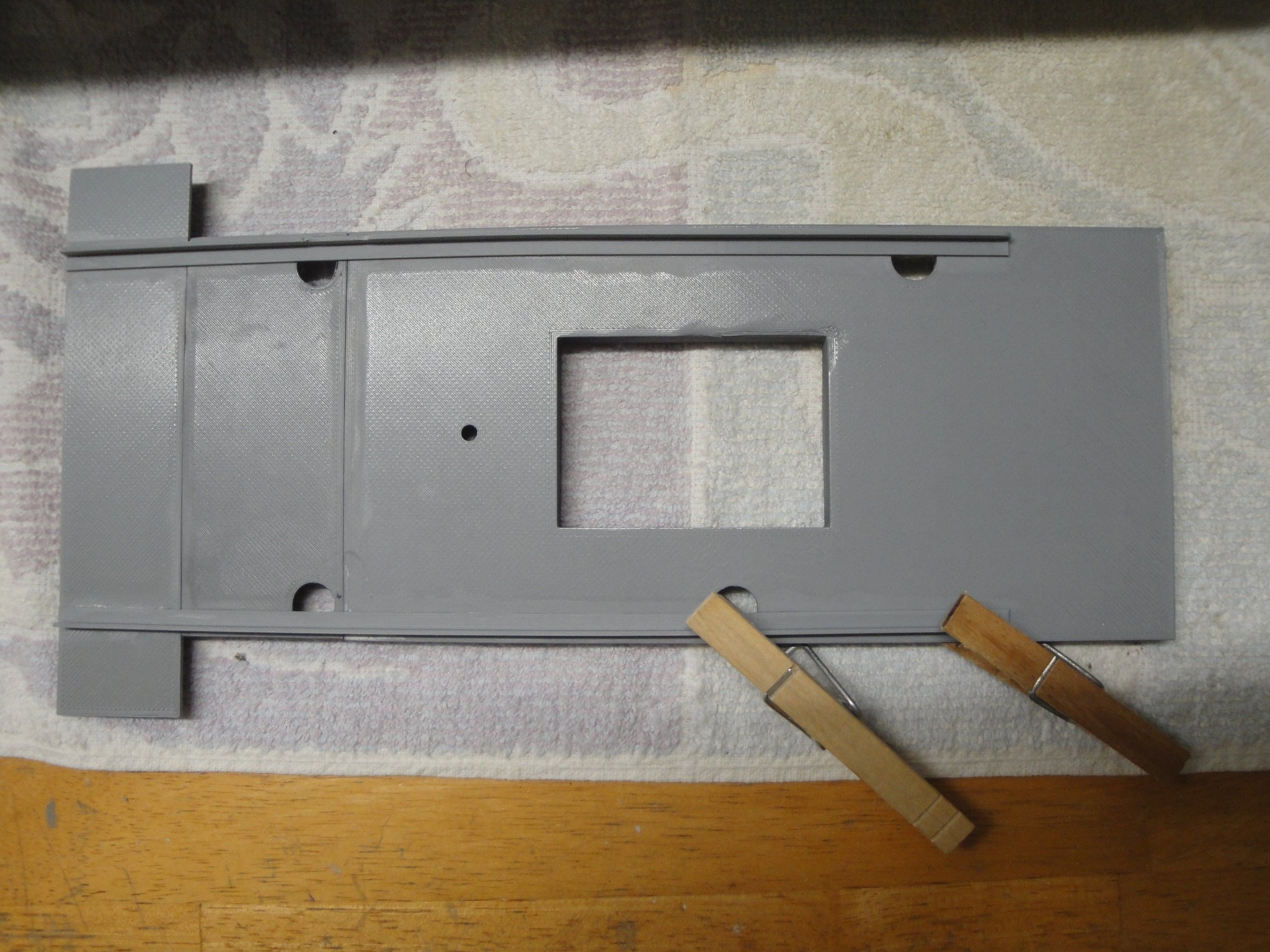
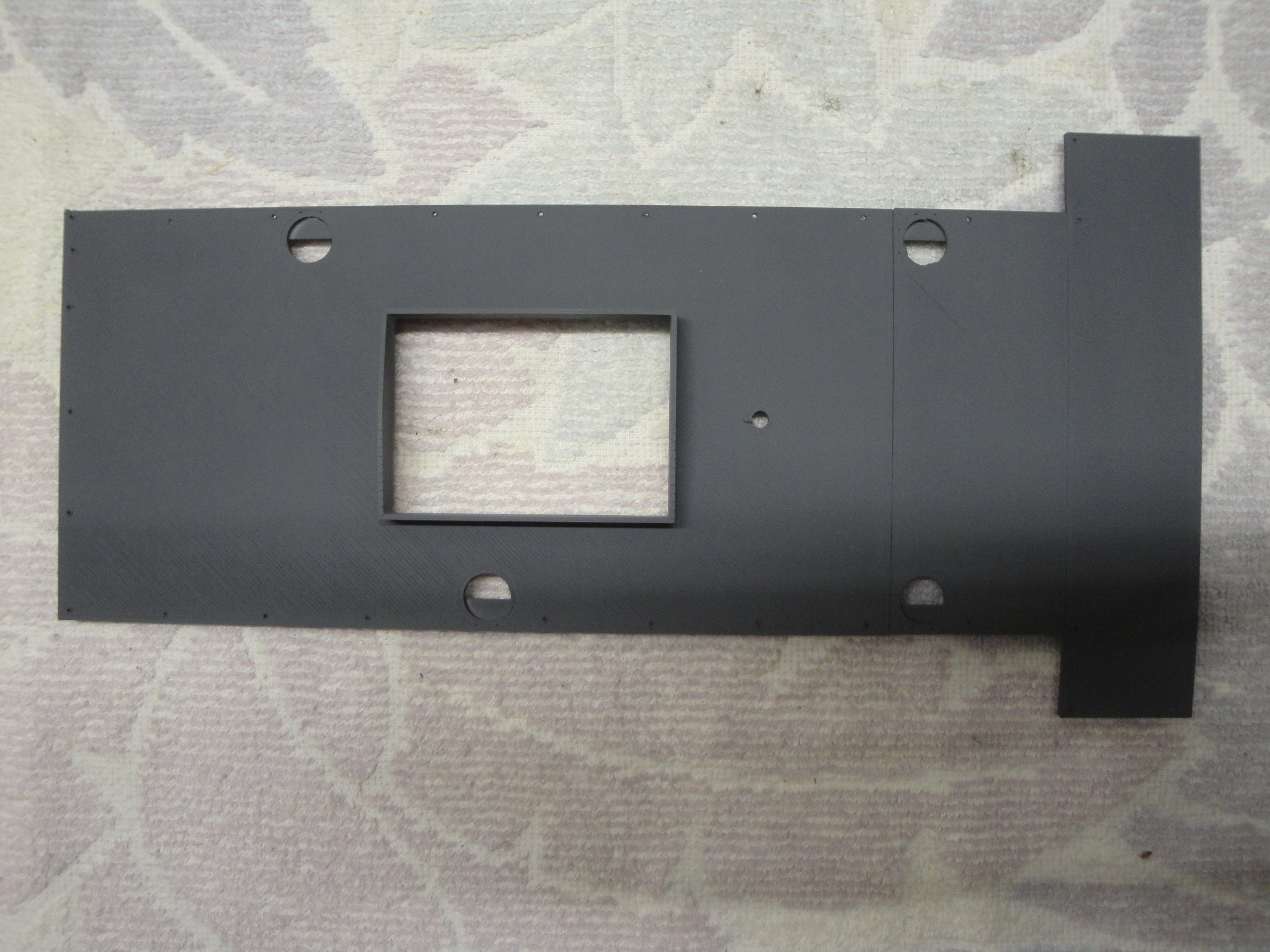
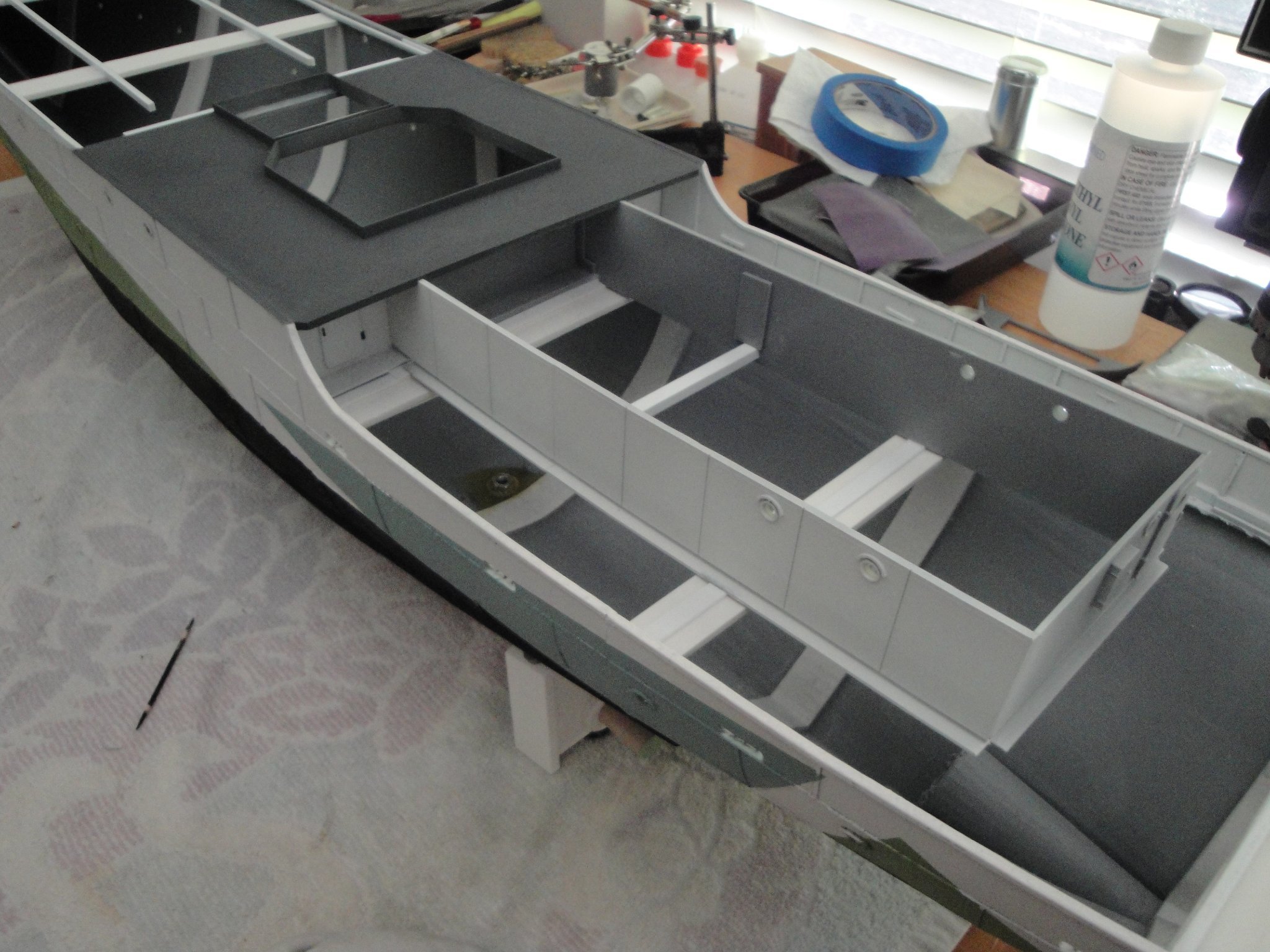
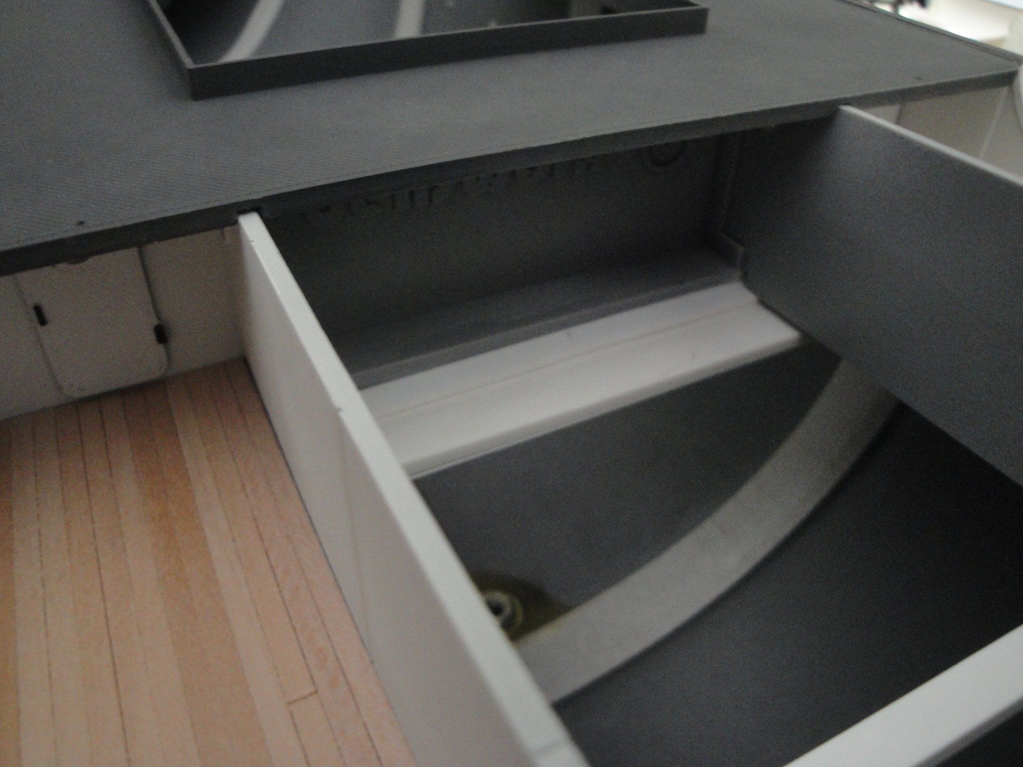
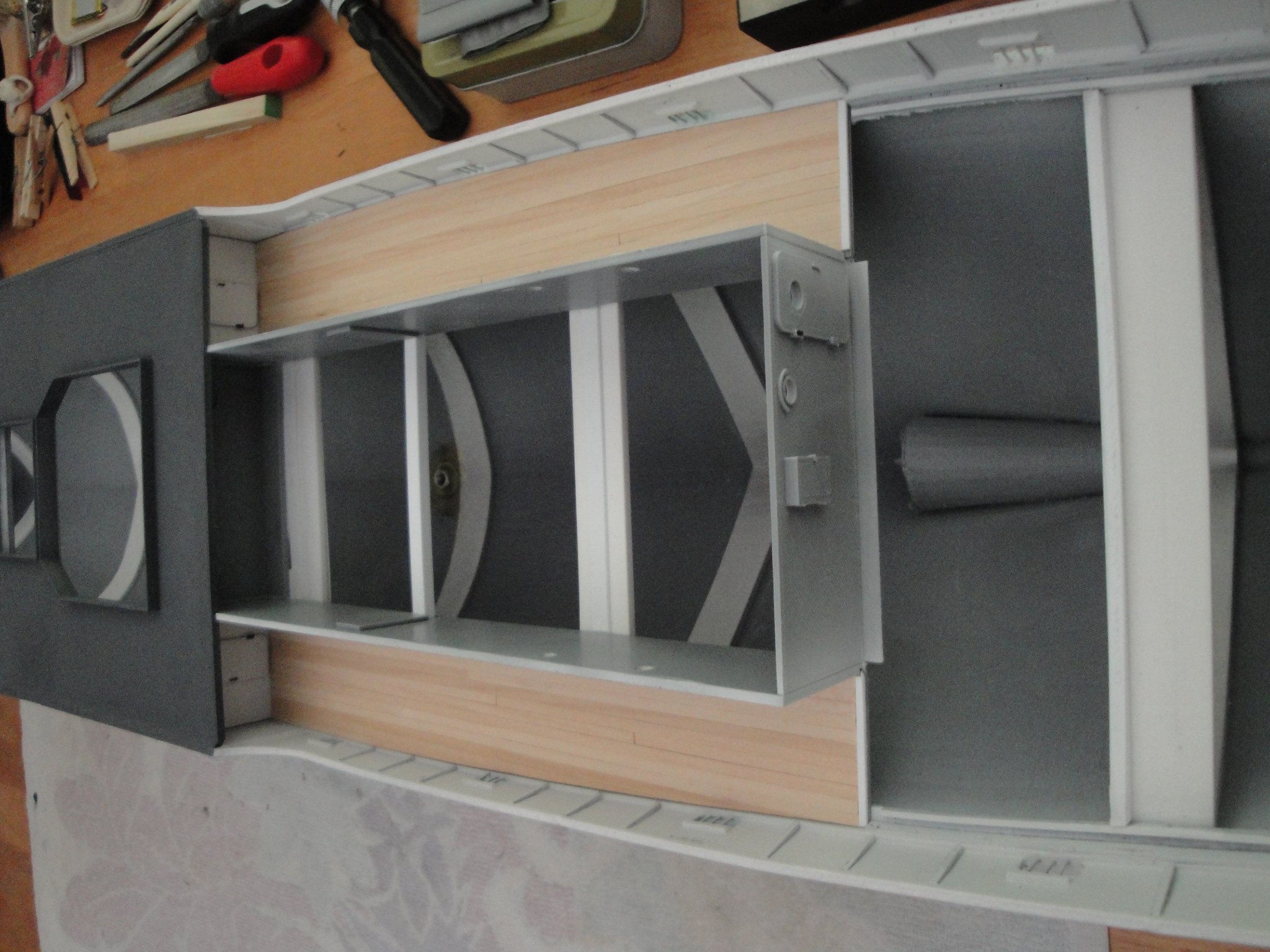
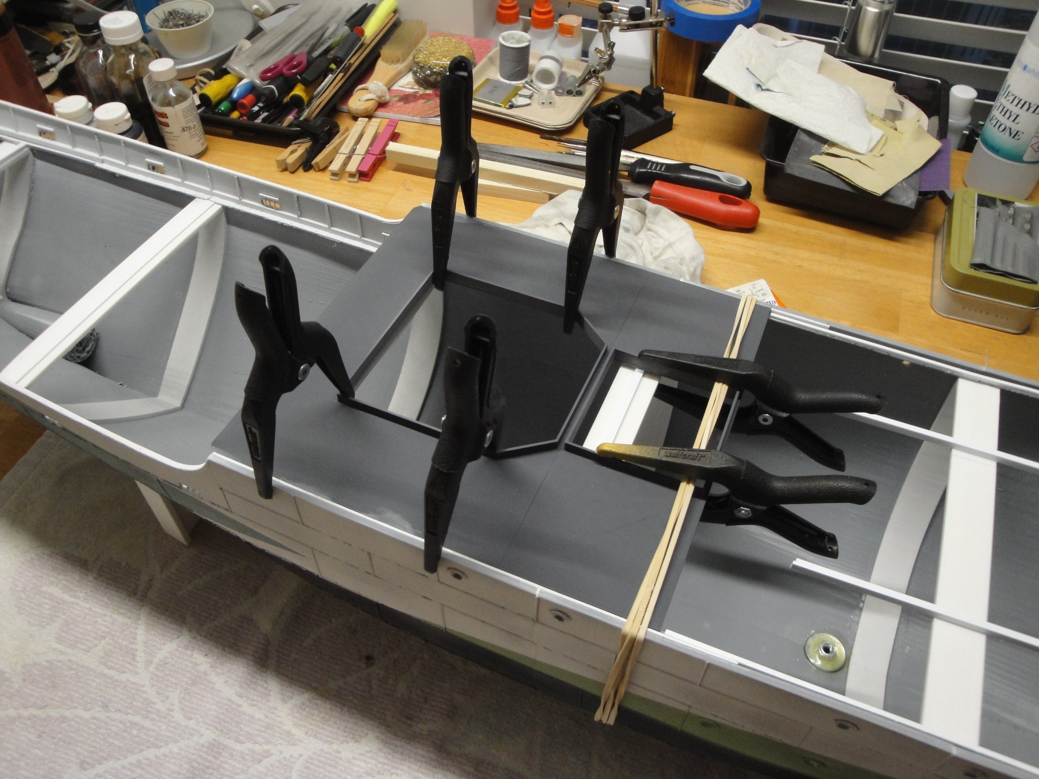
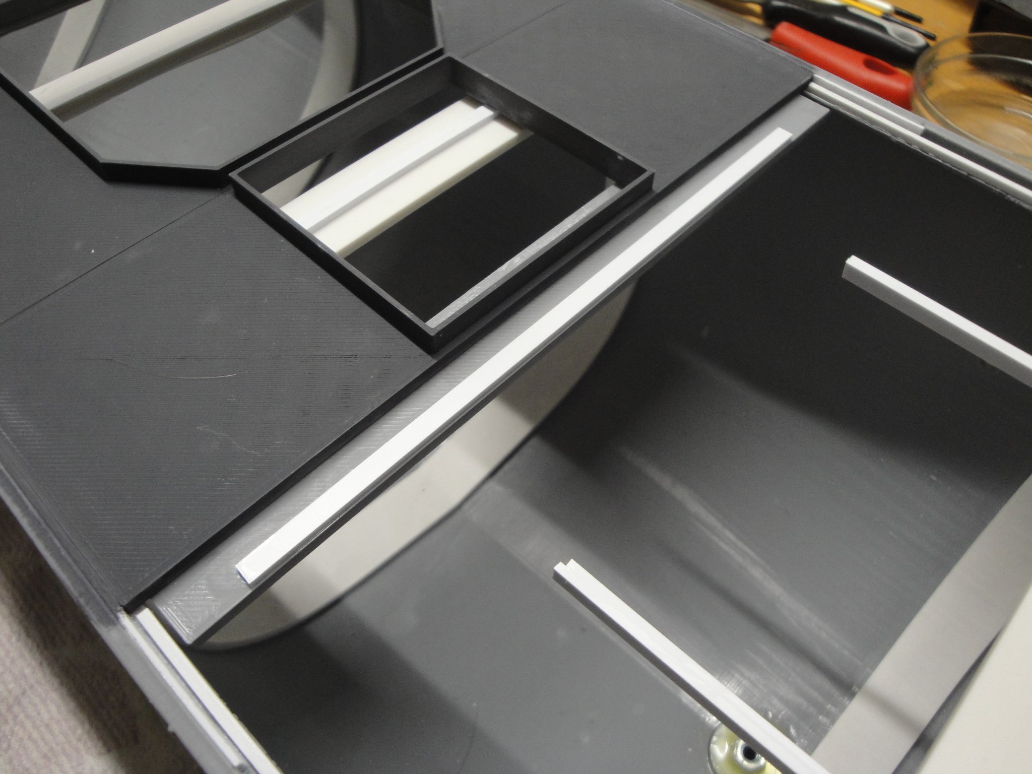
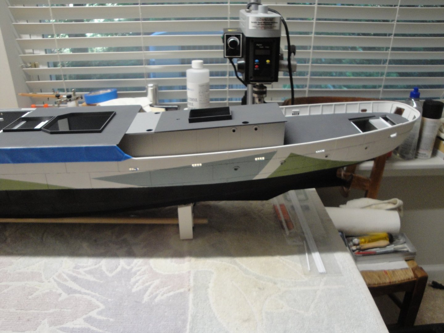
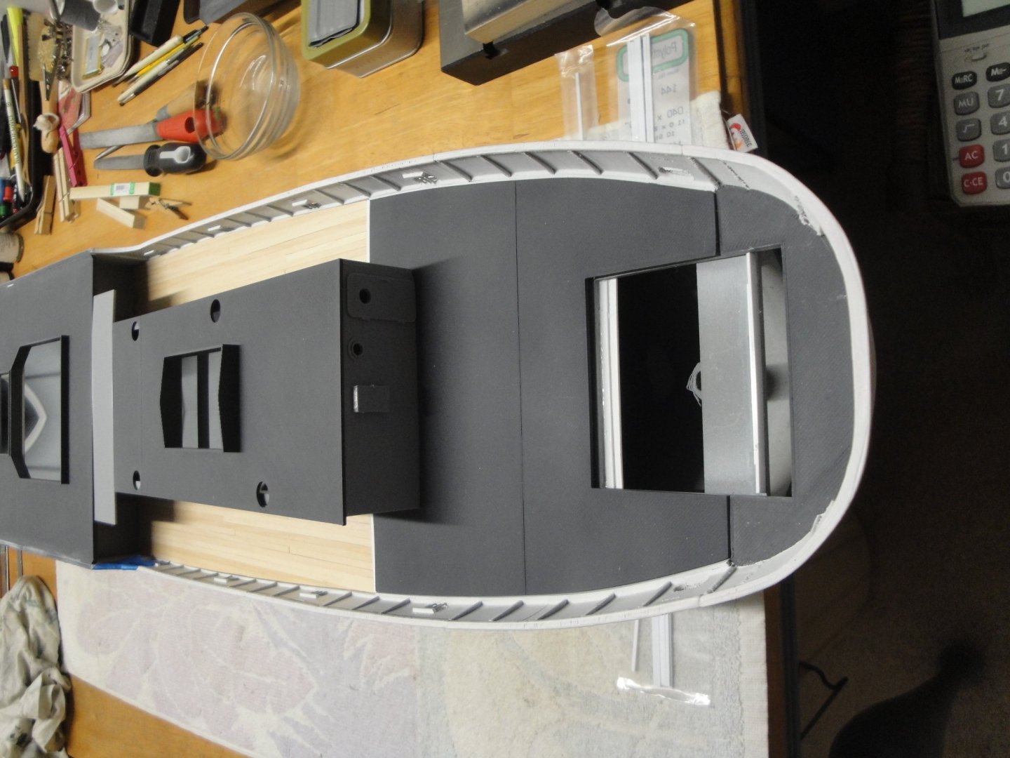
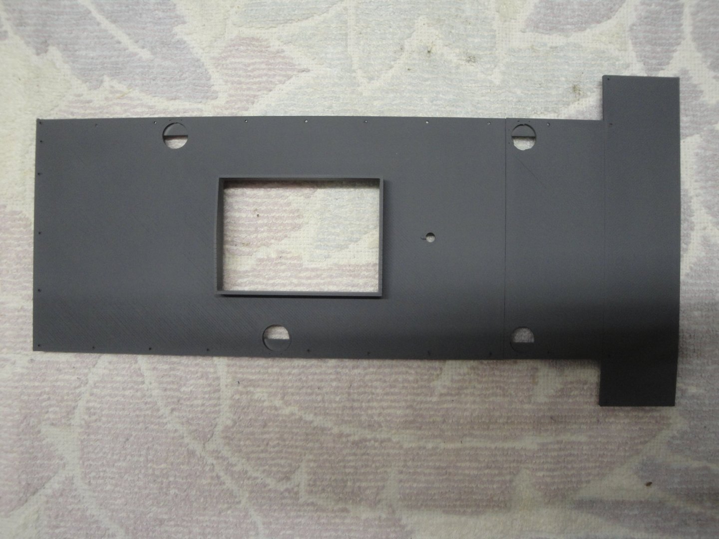
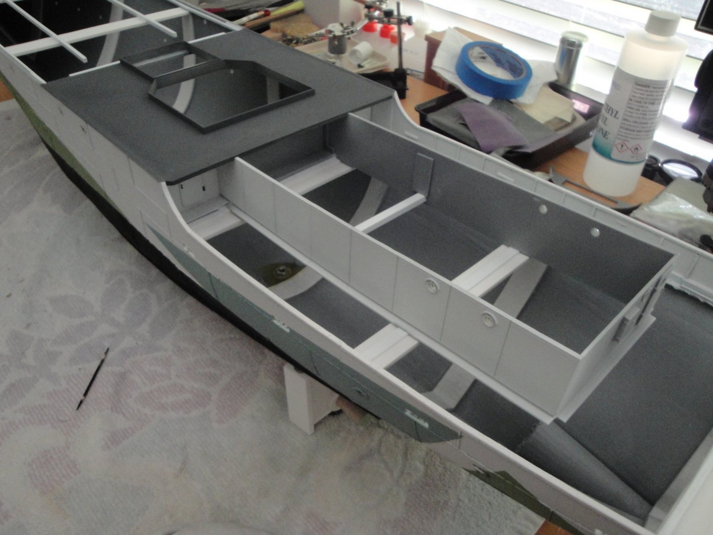
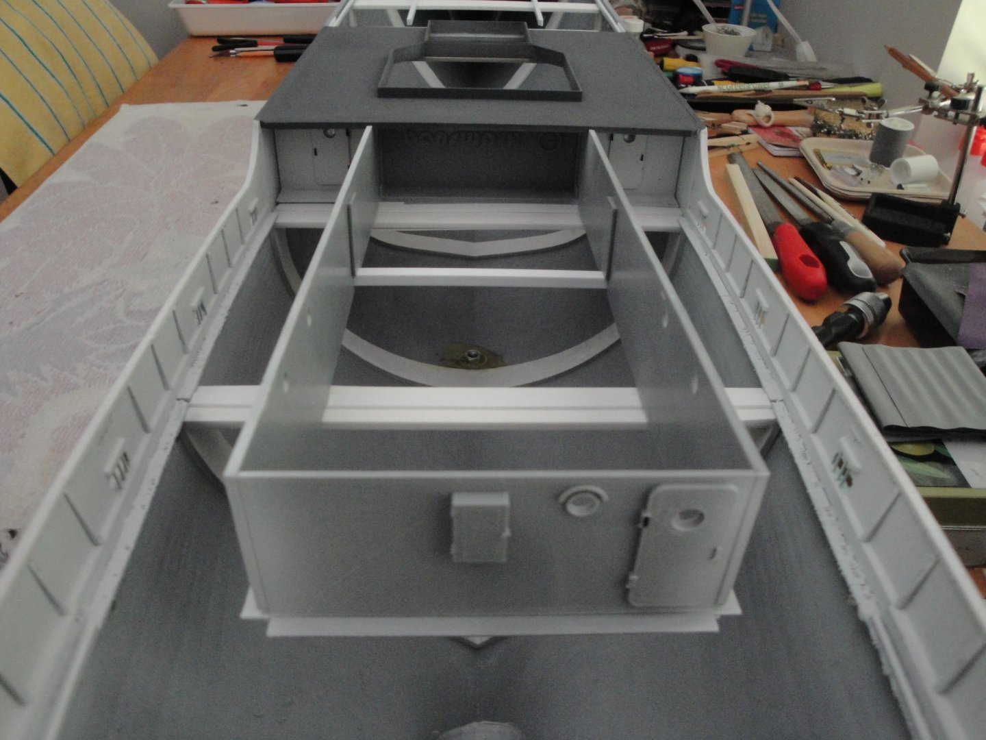
MODULE #5 Alright, time for a few updates. I am leading multiple fights at once with this model and cannot really work one module at a time. So without waiting, let's go to the Module #5. As a summary, here are the sub-assemblies that I have created on this model: Module #1: the bow or stem - Finished as you could see in previous posts. Module #2: the Gun and Edgehog - Not much done so far. Module #3a: The Wheel house. Soon to be unveiled... Module #3b: The deck - Nothing so far. Module #4a: The Galley - Almost completed - Mast being developed.... Module #4b: The Funnel house - Completed. Module #4c: The Dinghies.... a lot to do. Module #5: We are talking about it below.... Module #6: the stern and the depth charge launchers - Nothing much. The kit was developed around the HMS Agassiz and that particular section of the model does not match the Snowberry. The kit engine room is way too short and the rear platform located between the charge rails and the rear of the engine room is too wide. It looks like a dance floor and does not fit Snowberry. When you look at pictures of the Snowberry and actually most reworked Corvette, the engine room is much longer and comes close to the rear of the charge launchers. Modifying these parts is not easy because of the curvature of the cabin and of the decks. If I was a wizard in Sketchup, I could have taken the existing engine room parts and extended them, before printing. But I am not that wizard. So, we are going to have to do it, in the traditional modeler way: cutting, gluing, sanding....and repeat. Also, Snowberry has a set of inflatable Dinghies/Rafts sitting next to the funnel and two stairs linking the main deck with the rear deck. These aspects are completely missing on the Virtual kit. Some modifications are in order: Here you can see a piece of deck that I printed, using a deck joiner part and changing its size. I sized it exactly at 33 mm wide, 140 mm long and 1.6 mm thick. It fits perfectly between the main deck and the engine room roof, and will provide the base for two ladders/stairs going down to the rear deck. The rest of the space will be used for a couple of rafts. Now, we can see that the rear of the engine room is getting more realistic. The additional section is made by printing again the forward engine room walls and cutting the first panel off. These left and right panels are then glued to a second print of the rear wall. That is the beauty of printing your own parts: you can do it as many times as you want. From an aerial perspective, we now have the following: Below is the details of the engine room roofs: The rails provide a way to fit the roof in place and hold it tight, until its permanent gluing. Painted: Another major milestone, once everything has been fitted and tested many times, is the gluing of the engine room to the hull. Here again, I would recommend keeping all the hull join parts intact, as they are very useful to hold everything in place: Notice how well the kit is designed with the perfect indentation of the engine room walls into the very thick deck of Module #4: Then the 1.6 mm thickness of the engine room deck, fits perfectly flush with the main deck. More pictures of this major milestone: The U shape profile is used to prevent the sagging of the engine room walls, when you install the wooden decks. Hope you enjoy. Yves


- 321 replies
-
- 16
-
-
- Finished
- Flower-class
- (and 1 more)
-
Yes, GRP hulls are notorious for using demolding agents and that is not good for any paint. Thorough washing with detergent (Dawn is very aggressive as the name implies ... 😉 , light sanding and primer coat. Then you can do all you want. Yves
- 50 replies
-
- 3
-
-
- Marie Felling
- tug
- (and 3 more)
-
Exactly. Snowberry had Donald Duck instead of Flare Launchers. Yves
- 321 replies
-
- 5
-

-
- Finished
- Flower-class
- (and 1 more)
-
Lancia Assunta by maurino
yvesvidal replied to maurino's topic in - Build logs for subjects built 1901 - Present Day
Very cool. Yves -
Ras, I would use thick aluminum foil. Try to buy the heavy duty kind and do some trials on a piece of wood. The junction will have to be done very carefully, like welding seams. It is pretty much the same concept when they use copper plates on period ships.....just larger plates. Yves
-
Yes, definitely a big improvement over the kit supplied gun. I cannot even imagine what it would cost in 1/48th scale.... 😞 However, the good thing is that it is way too modern for the Snowberry..... 🙂 Yves
- 321 replies
-
- 7
-
-
- Finished
- Flower-class
- (and 1 more)
-
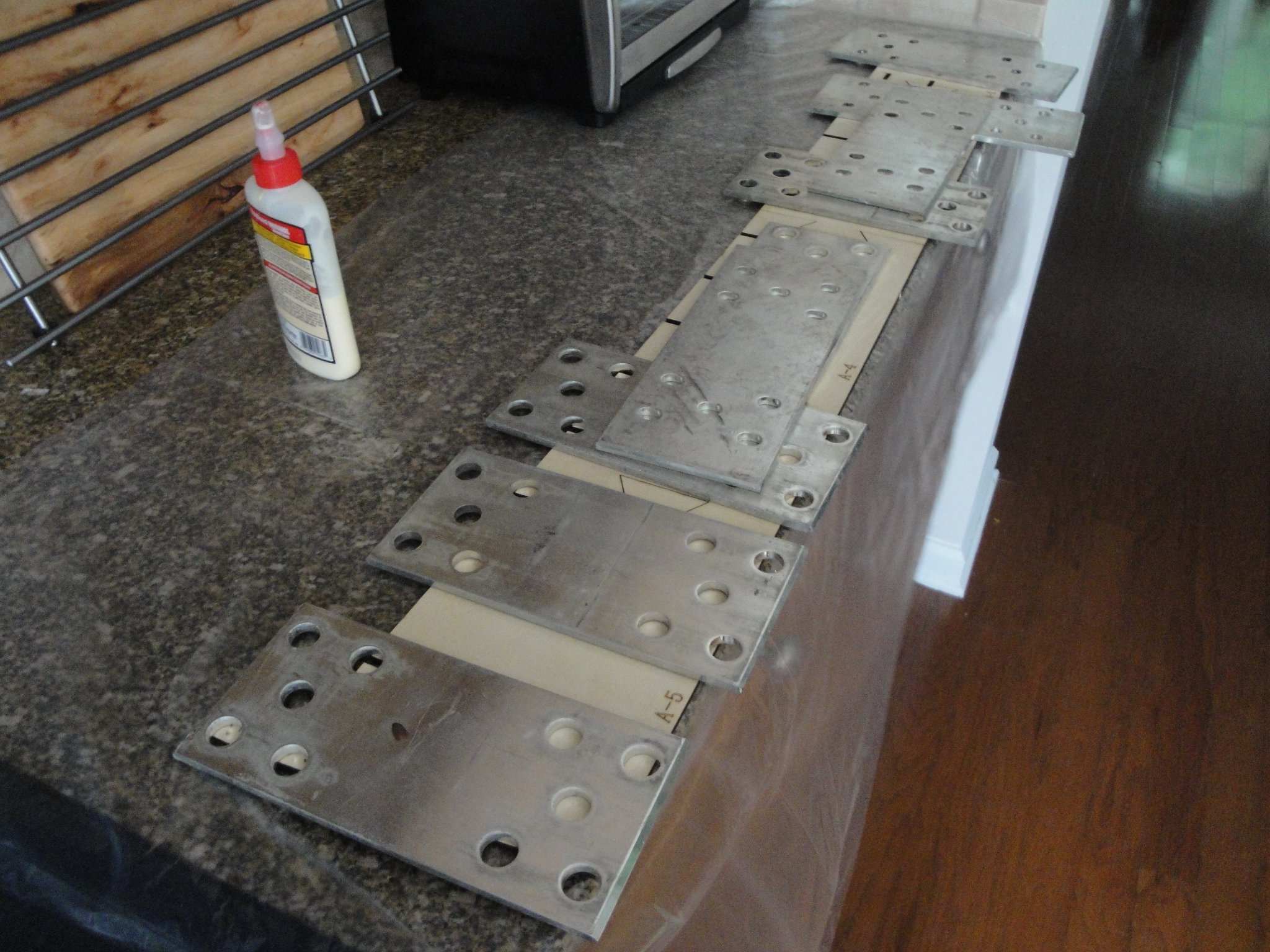
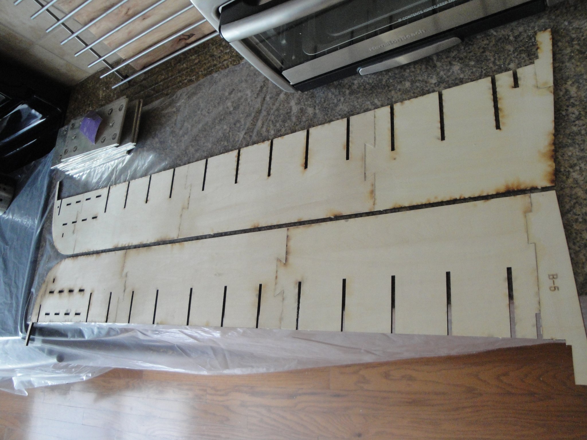
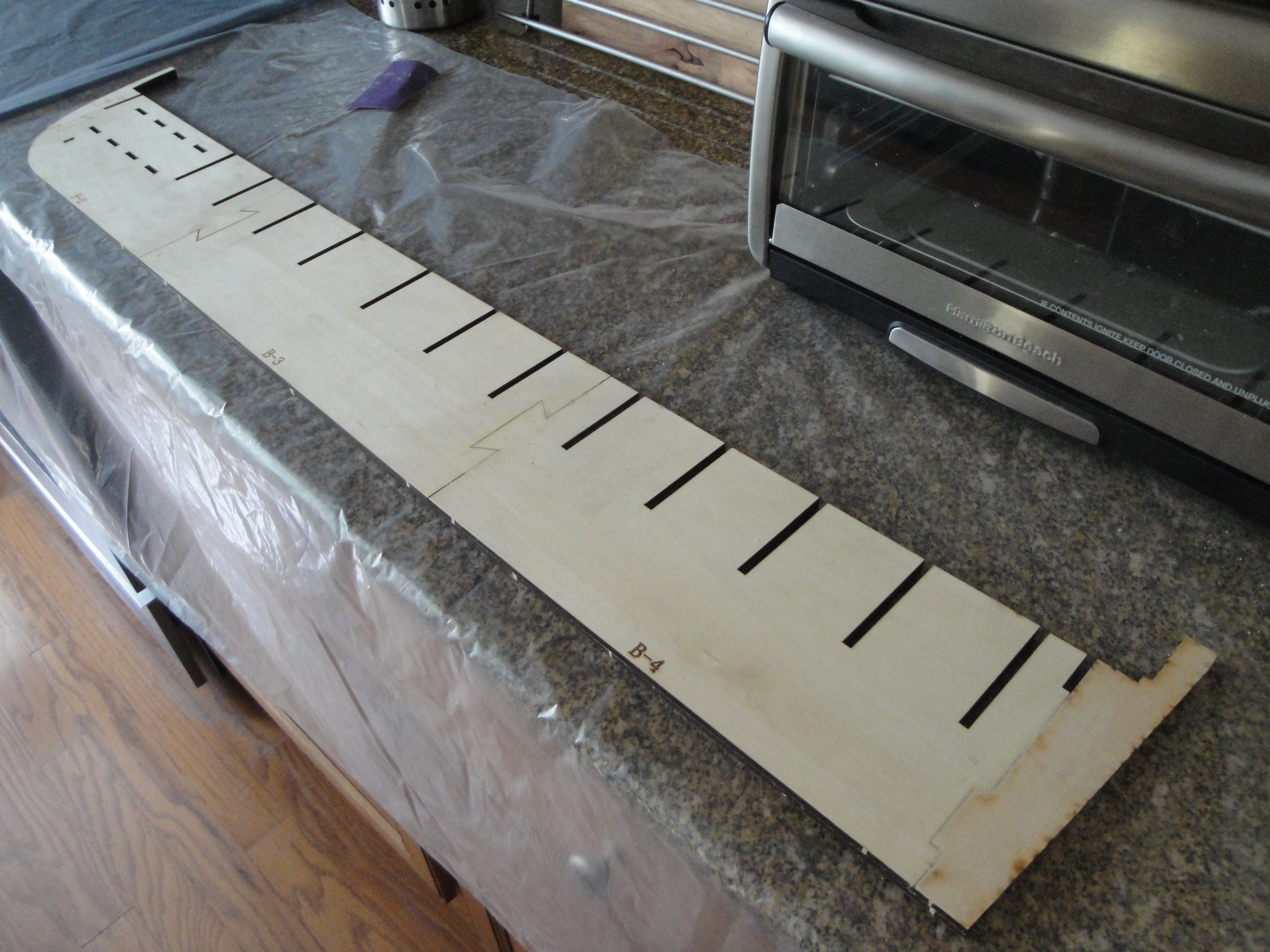
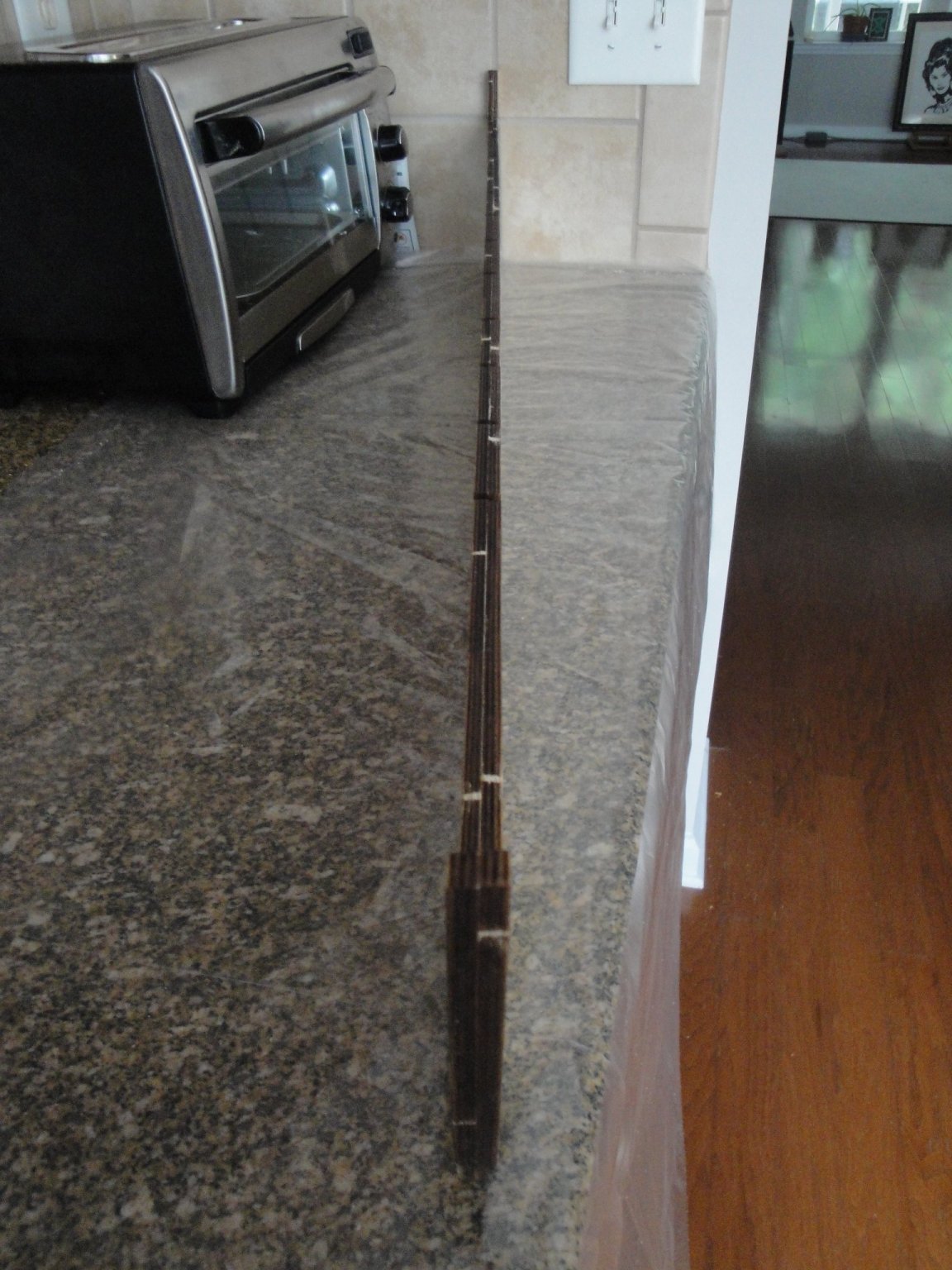
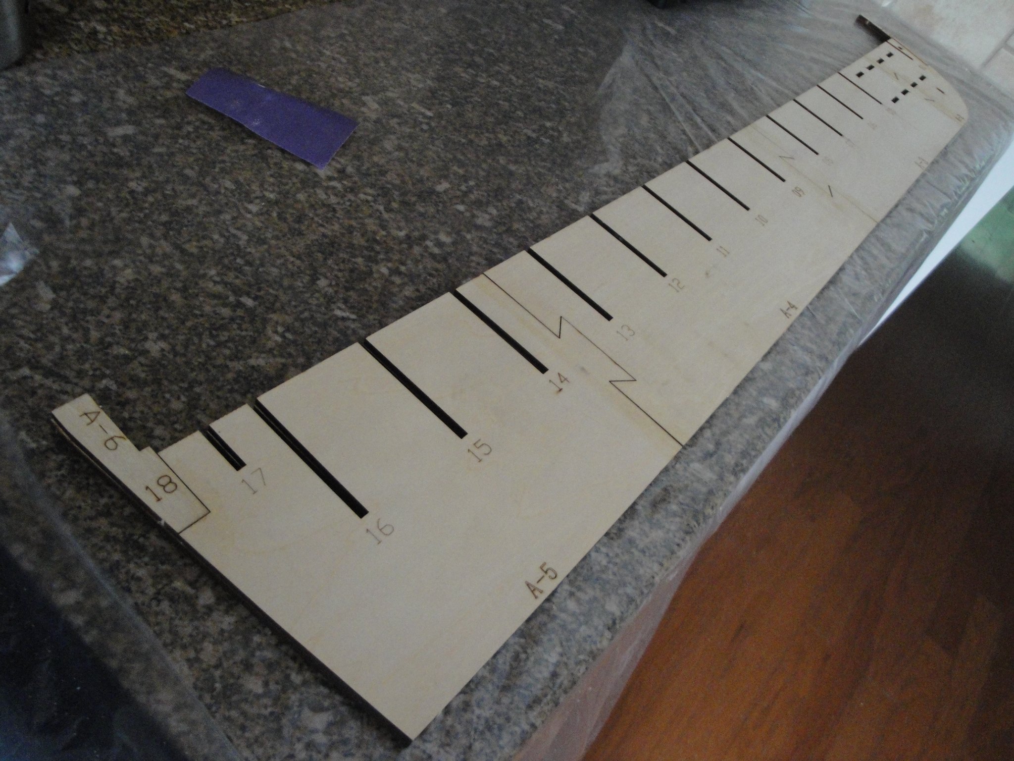
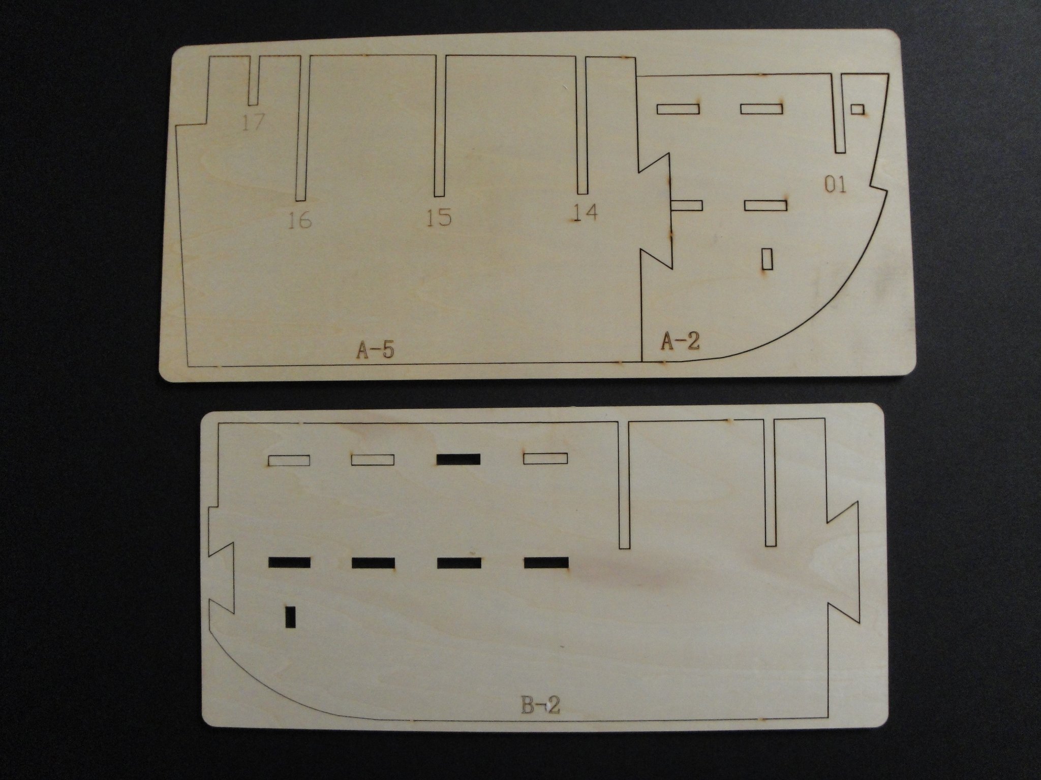
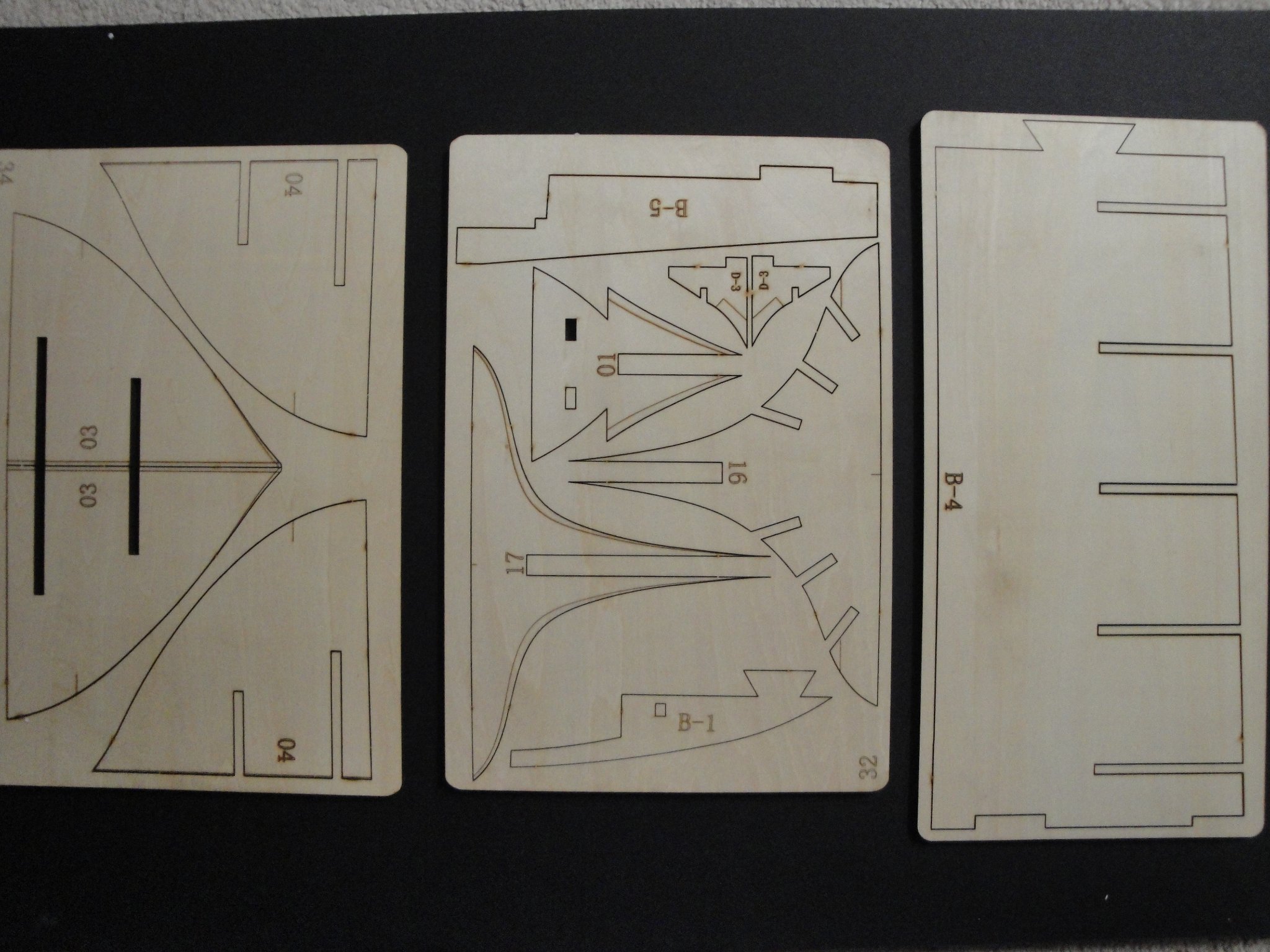
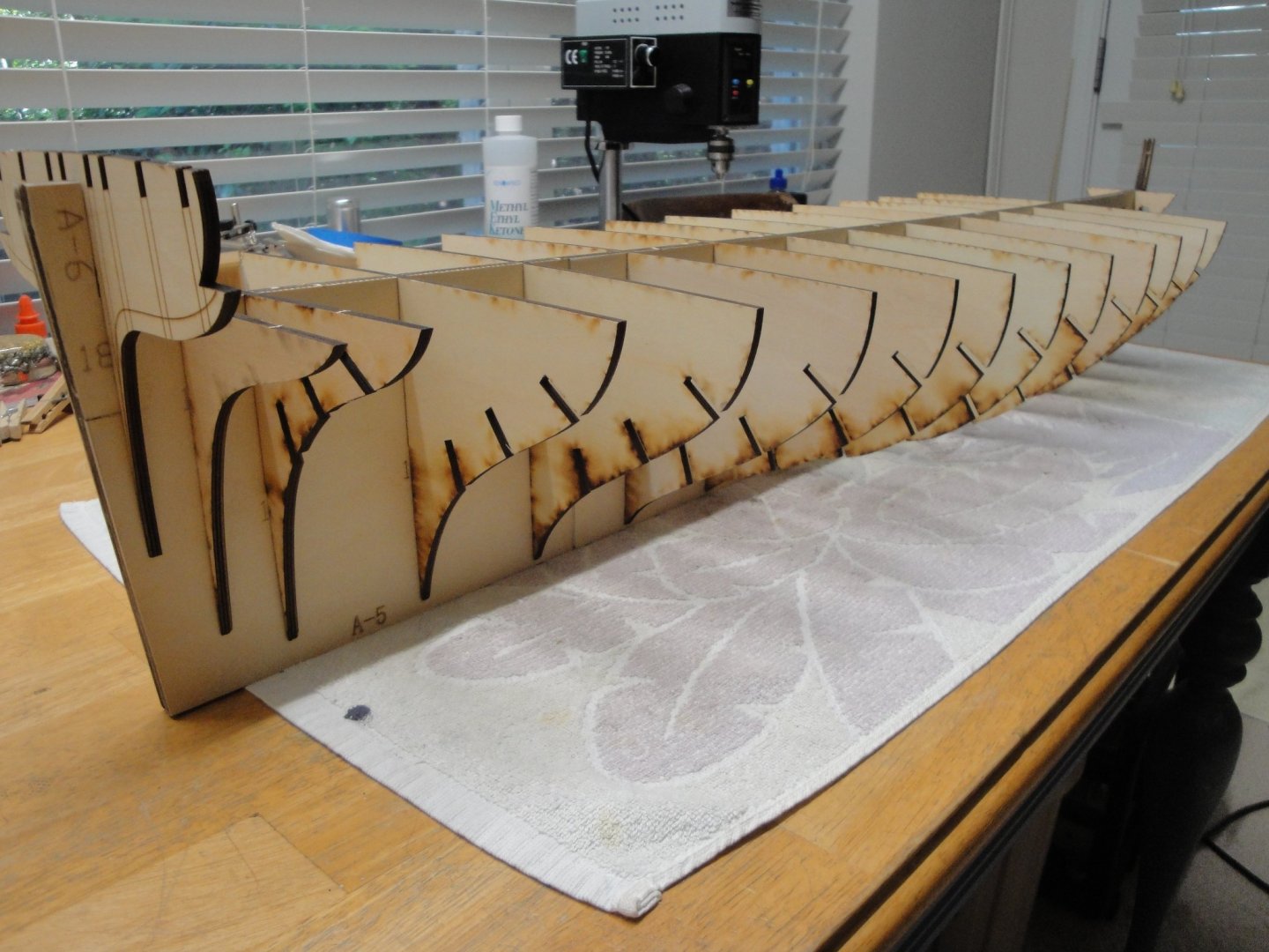
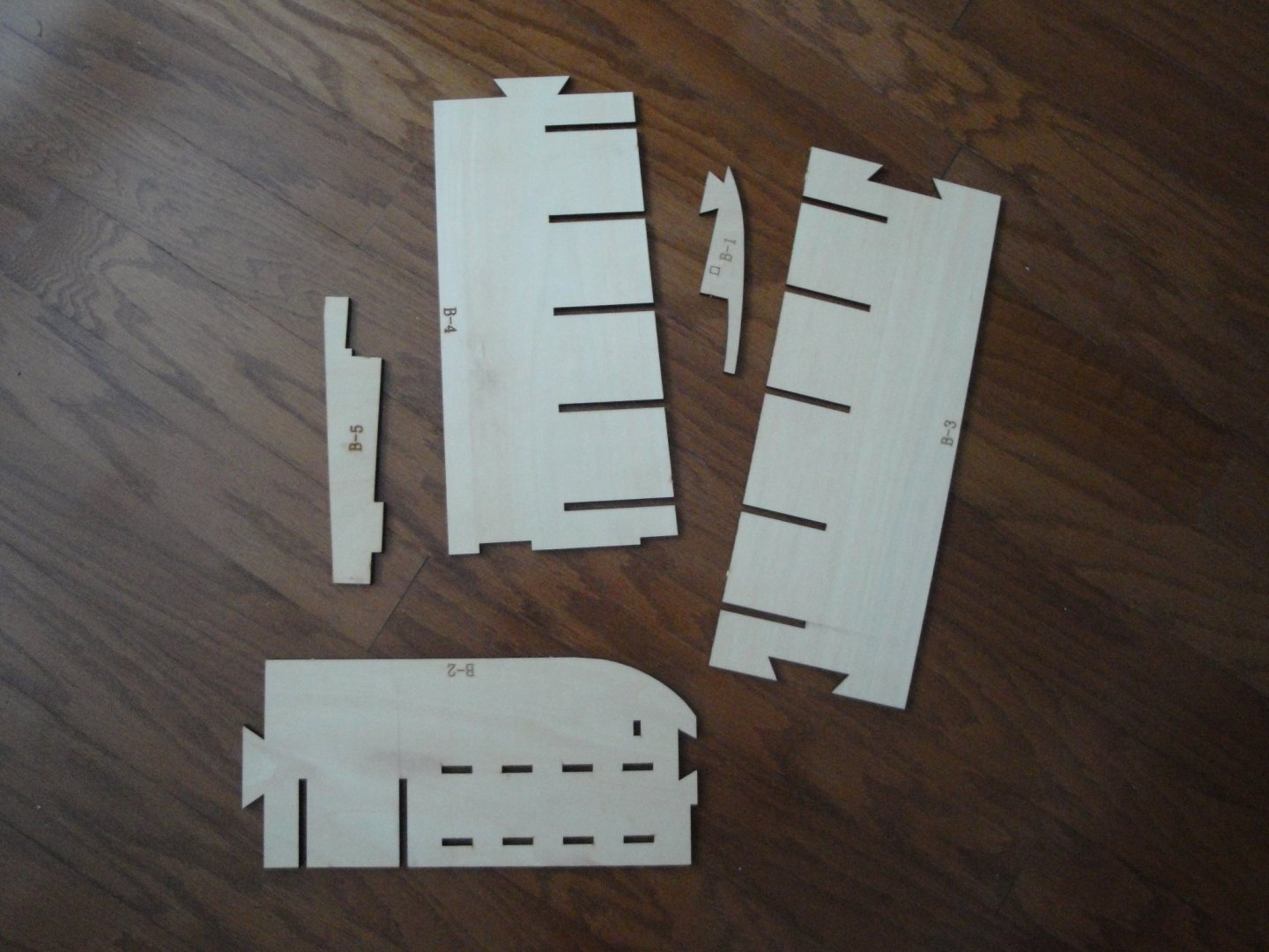
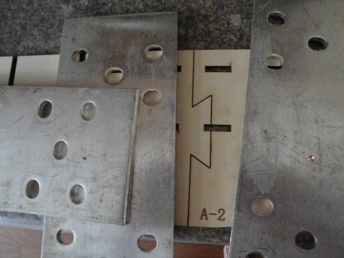
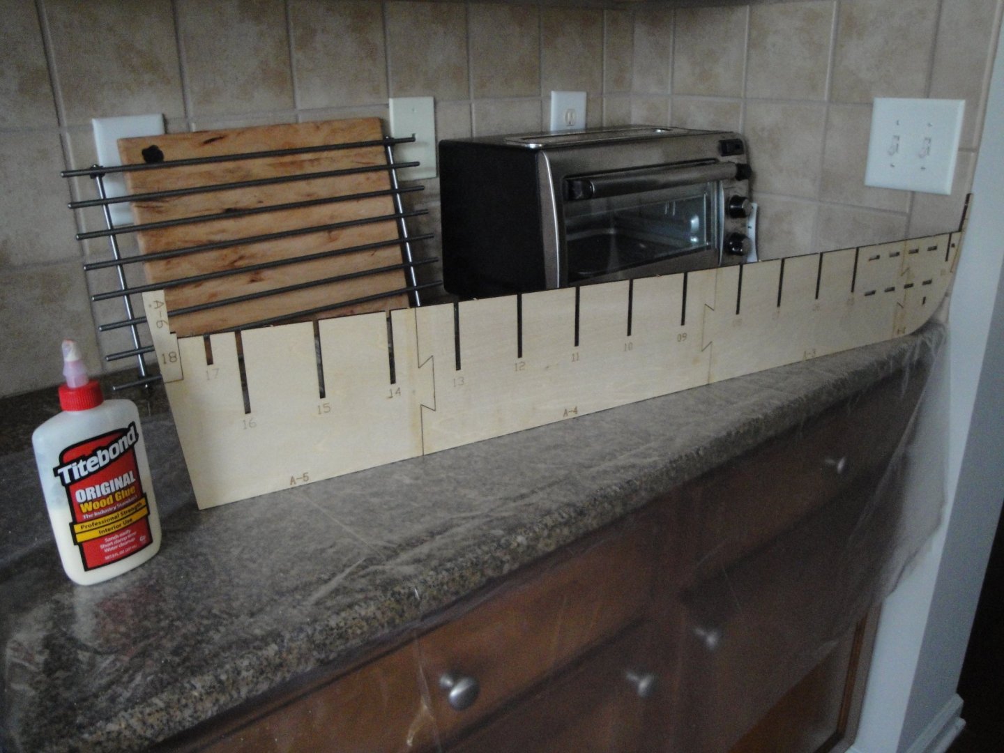
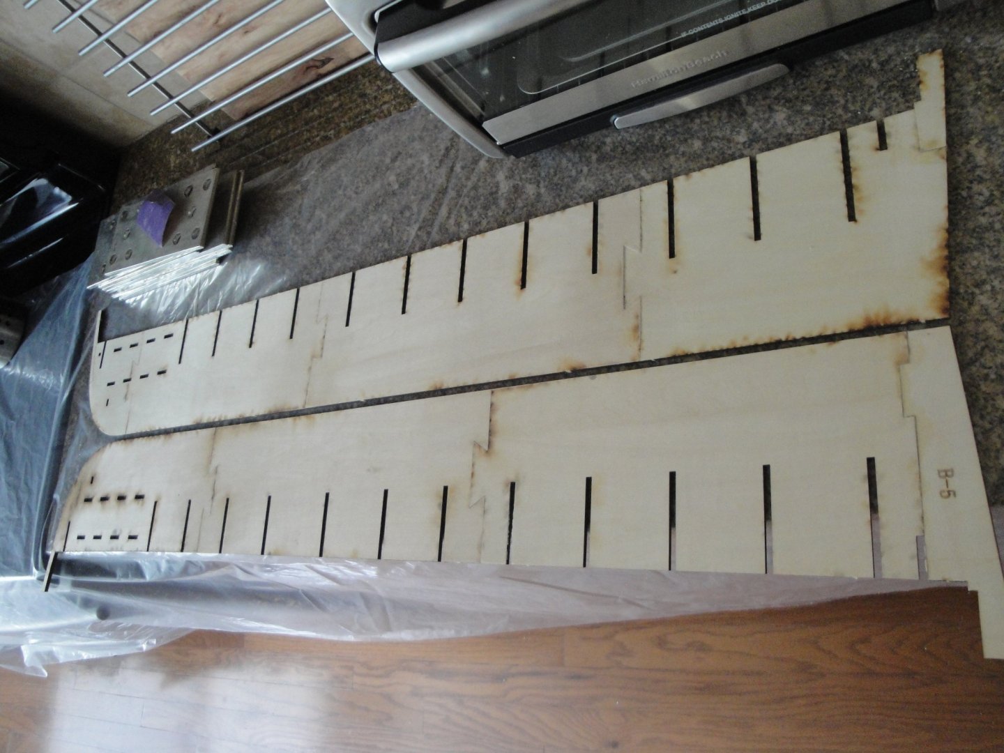
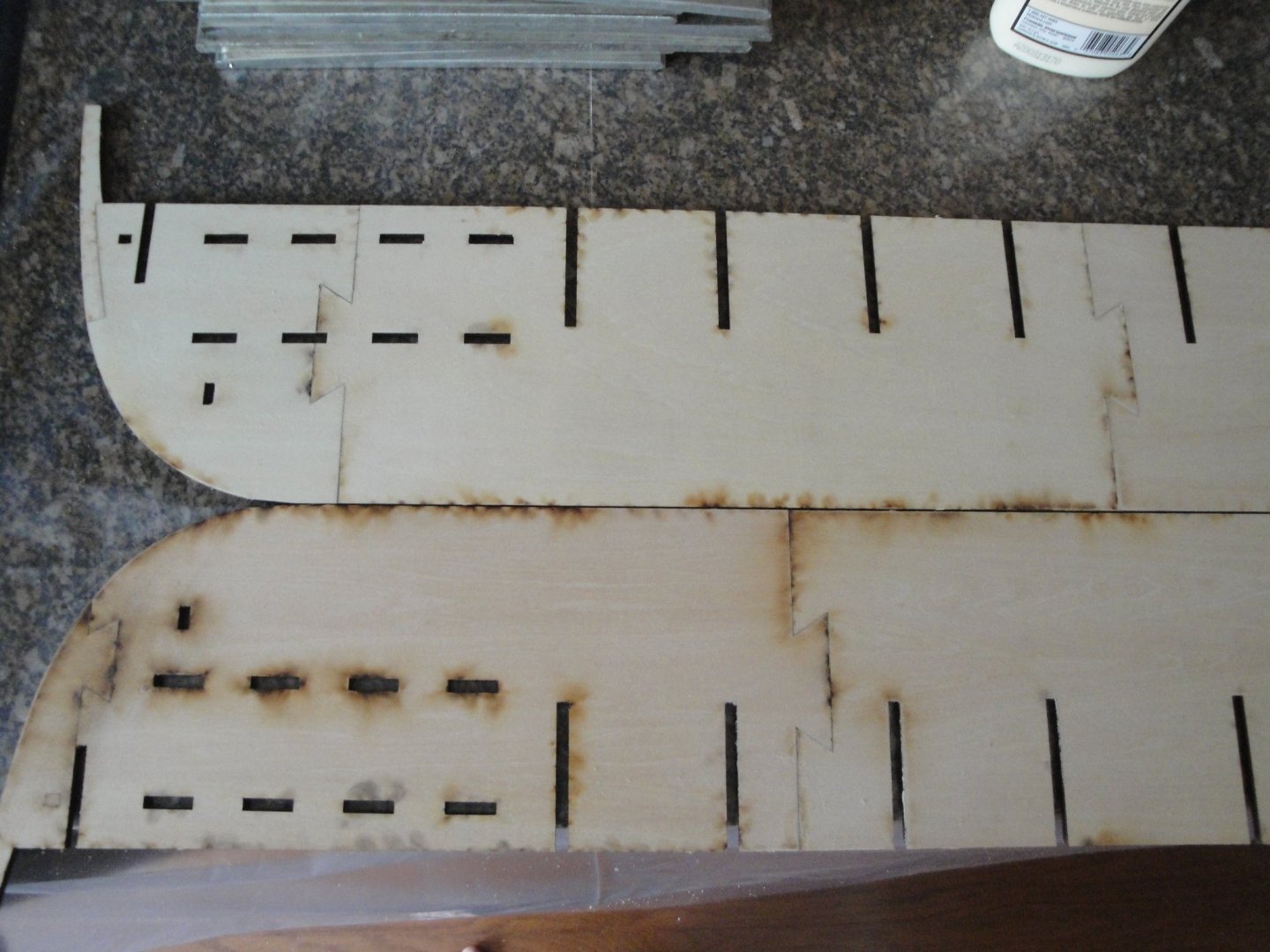
So, I could not help myself and had to start the kit and glue some wood. I am sure you will understand my struggle.... Building the main spine of the vessel (steps #1 and #2): The spine is made of two layers (A's and B's) that are sandwiched together. The A's side is drying. You have to have a perfectly plane surface and a kitchen counter top made of granite seemed ideal for that purpose: I am using plates of heavy copper to apply a significant amount of pressure to each side. The dovetailing is very nice and precise. I did not remove the charring and I am glad I kept it, as the parts are fitting perfectly. One side is done: This is going to be a massive hull ! Both sides are ready to be sandwiched: You can see that the cuts are staggered on each side, allowing a very solid and sturdy spine, once glued: Et voila.... The A side has all the markings for the bulkheads. And yes, it is straight.... I still have to do some sanding to put the two sides perfectly smooth and square. Yves


- 507 replies
-
- 20
-
-
-
That sounds like an interesting project or projects, I should say. Yves
-
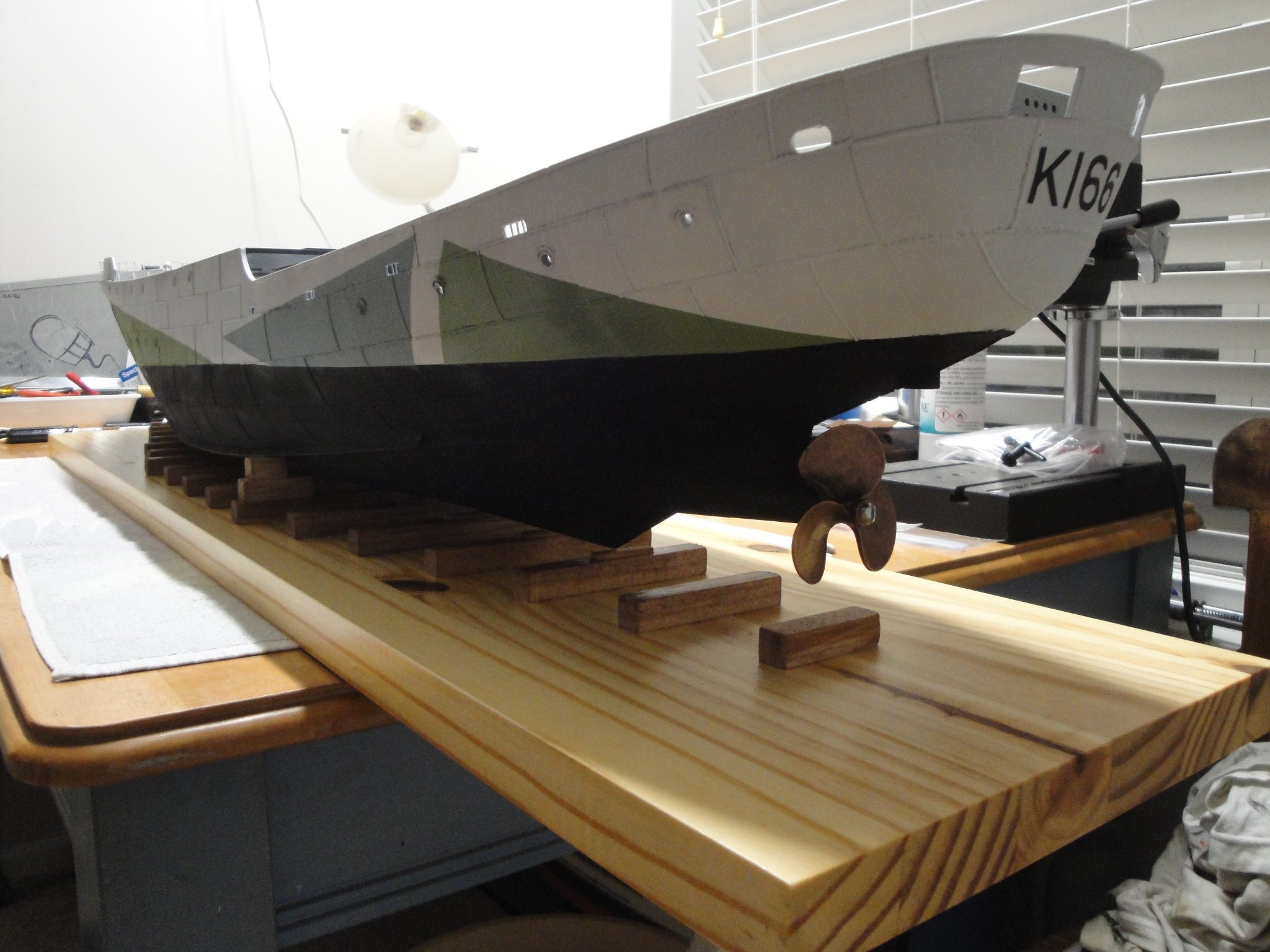
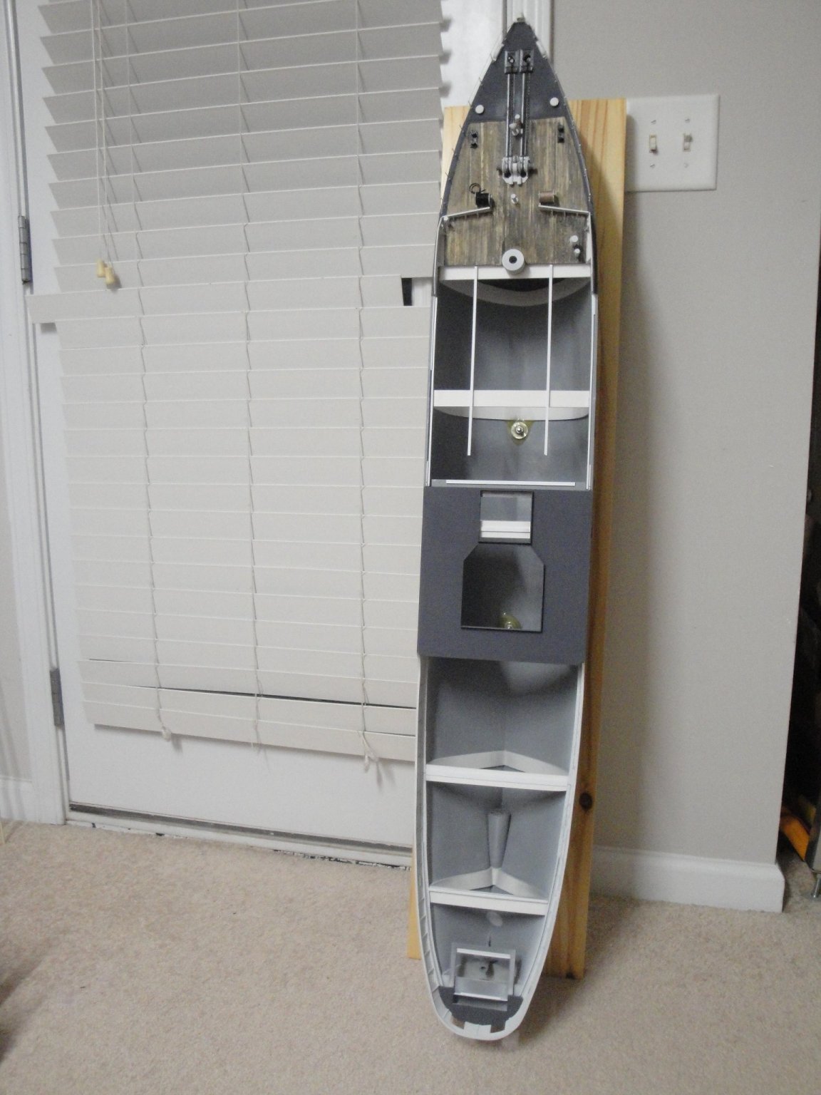
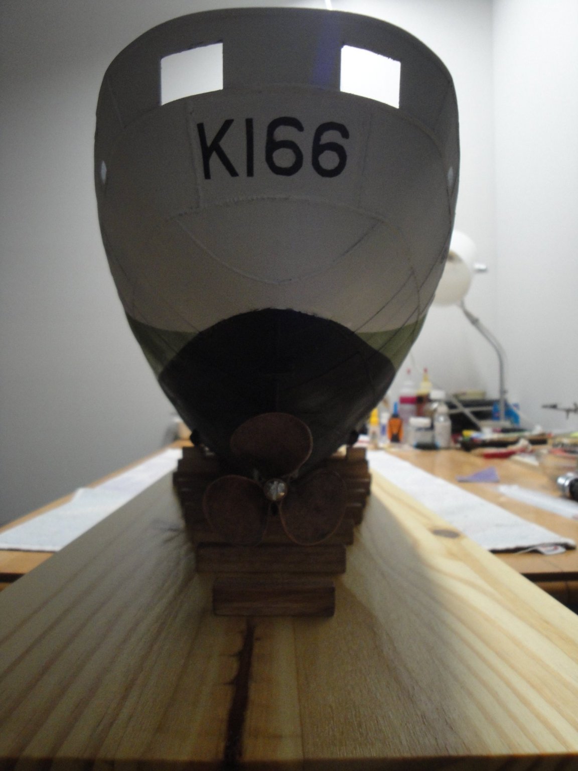
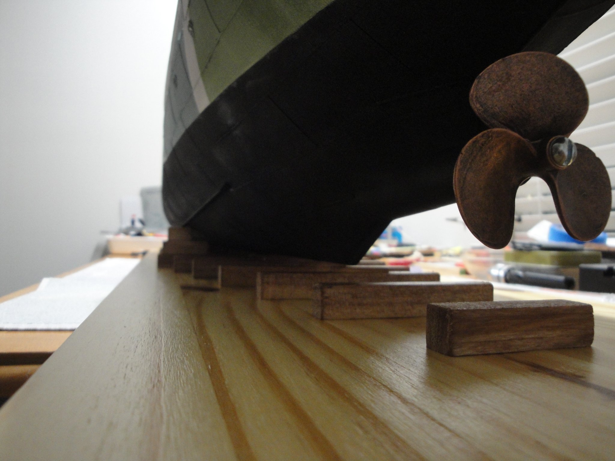
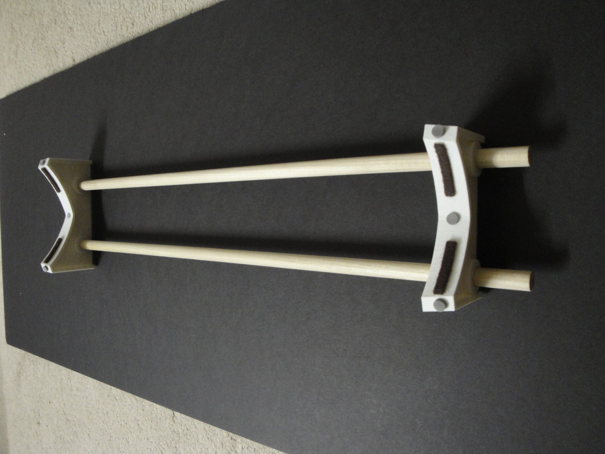
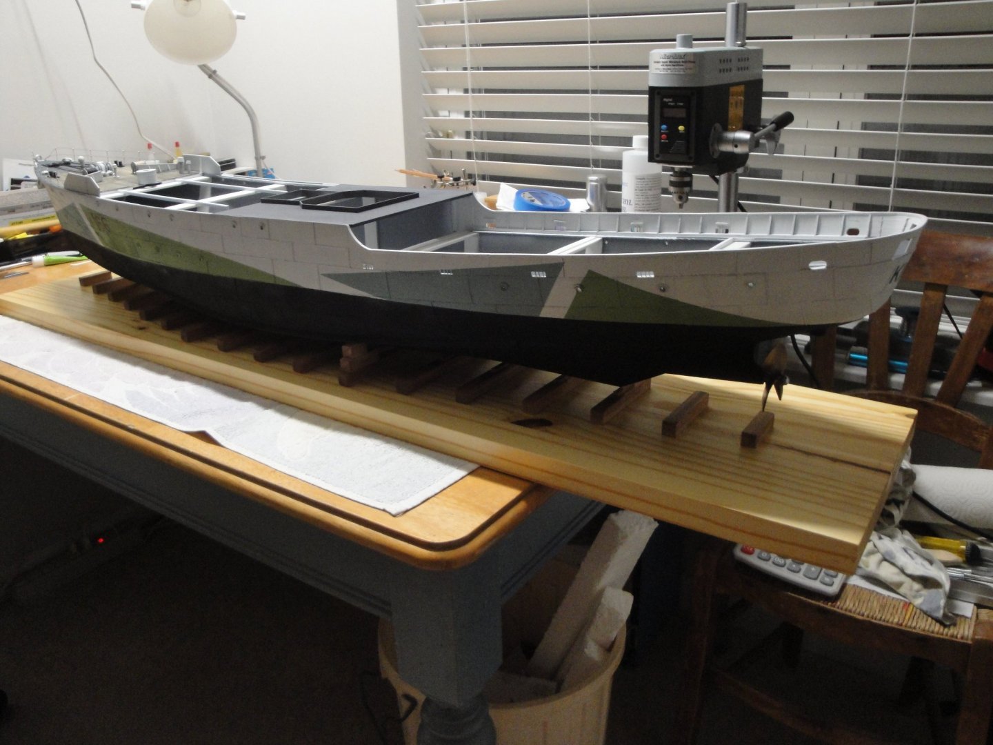
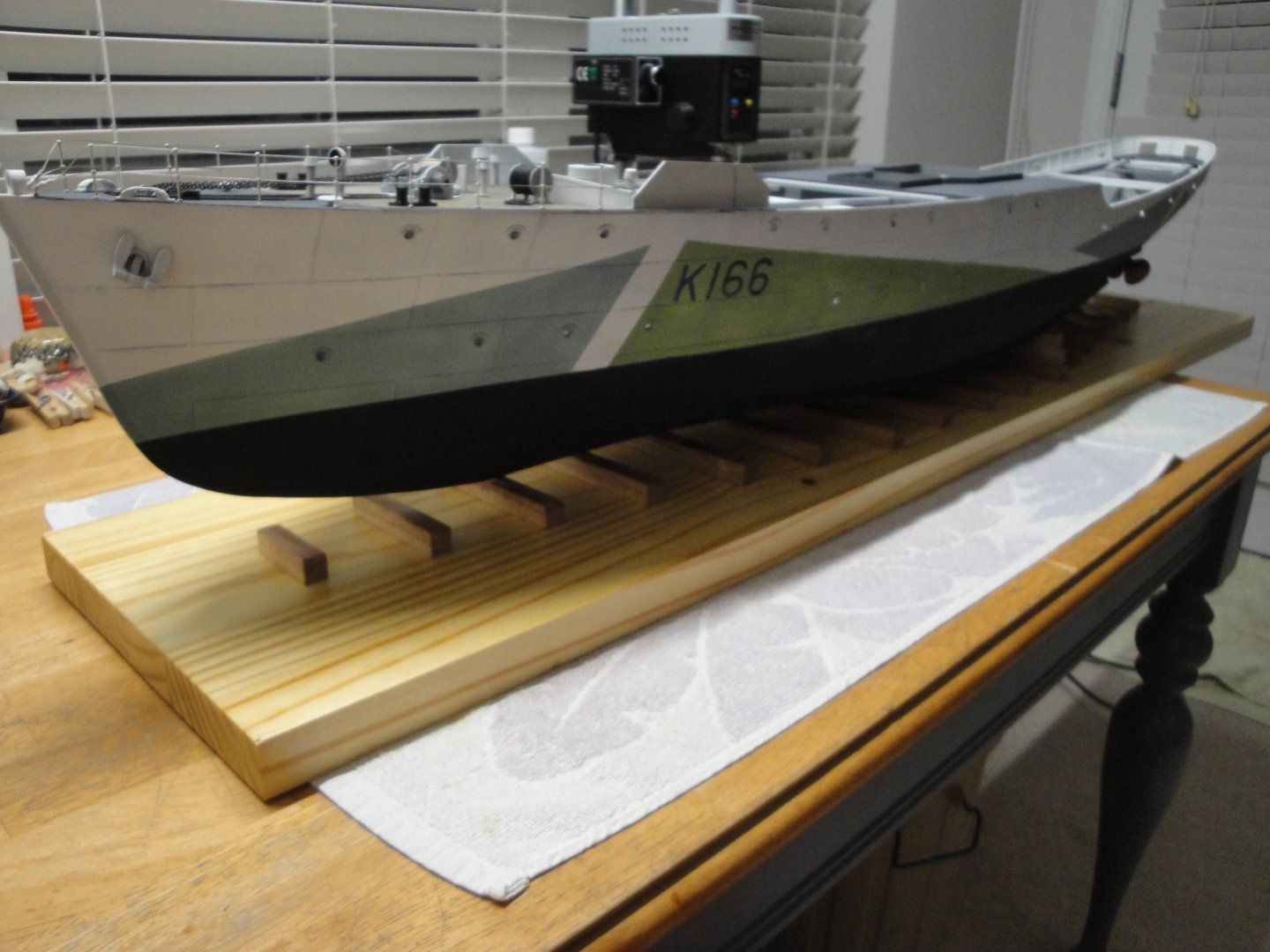
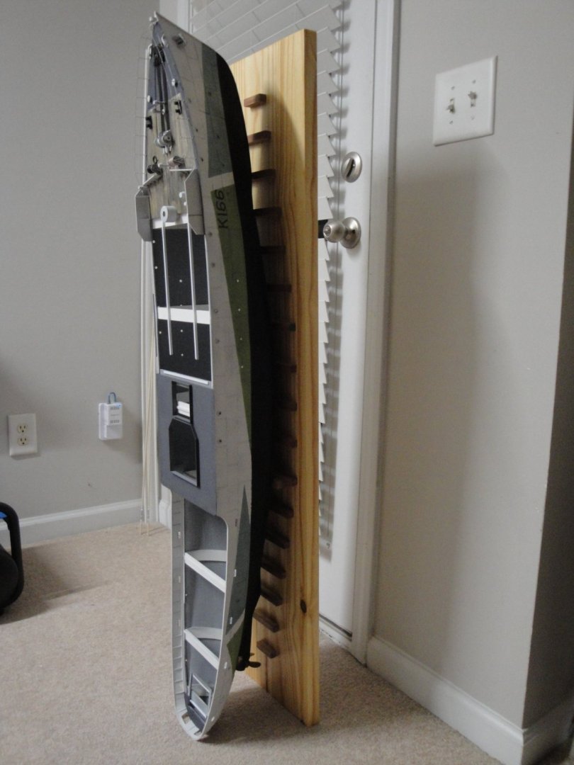
The display stand has been finalized: The ship is secured by two #10 bolts and rests on soft piece of Balsa wood, stained with cherry wood color. It may not be the prettiest display stand, but it it is sturdy and allows me to store the project vertically: It even holds by itself..... I will keep using the Kit provided stand to work on the model. It is a lot lighter and more maneuverable: Yves


- 321 replies
-
- 16
-
-
- Finished
- Flower-class
- (and 1 more)
-
Another beautiful ship from a renowned designer. Cannot go wrong.... Yves
- 36 replies
-
- 4
-
-
- vanguard models
- Erycina
- (and 2 more)
-
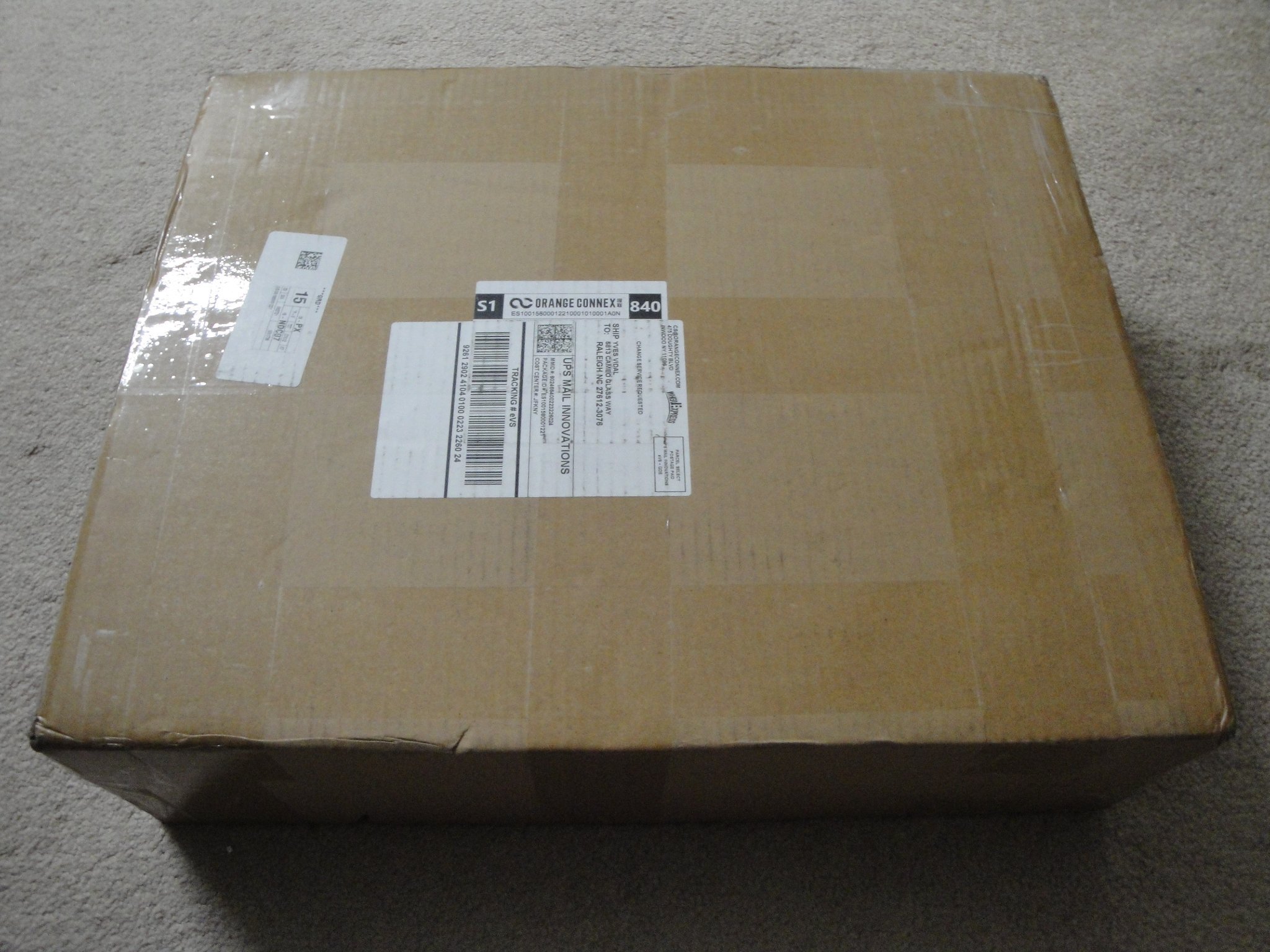
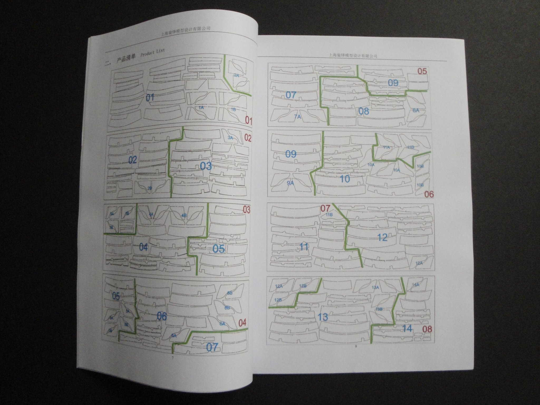
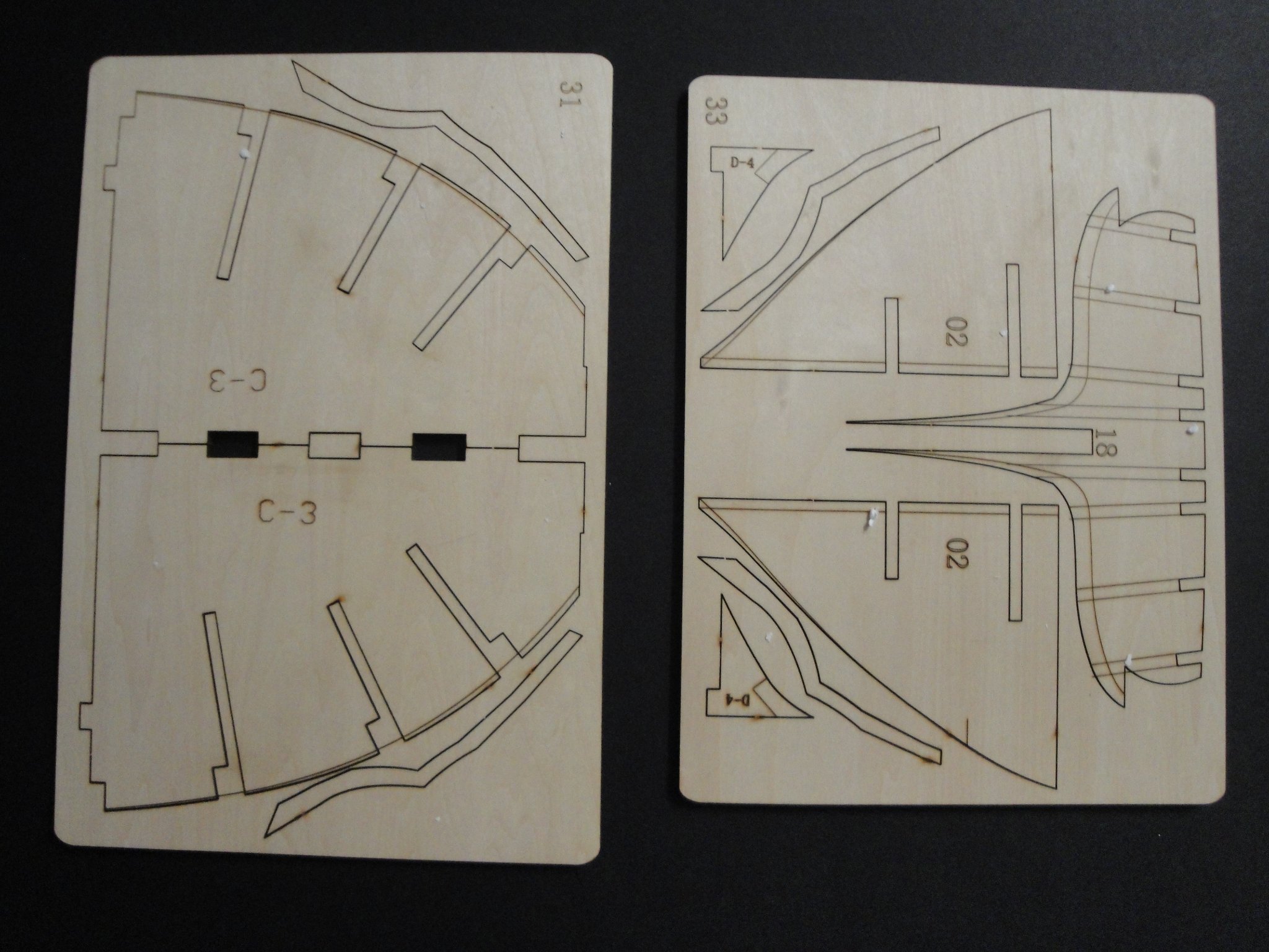
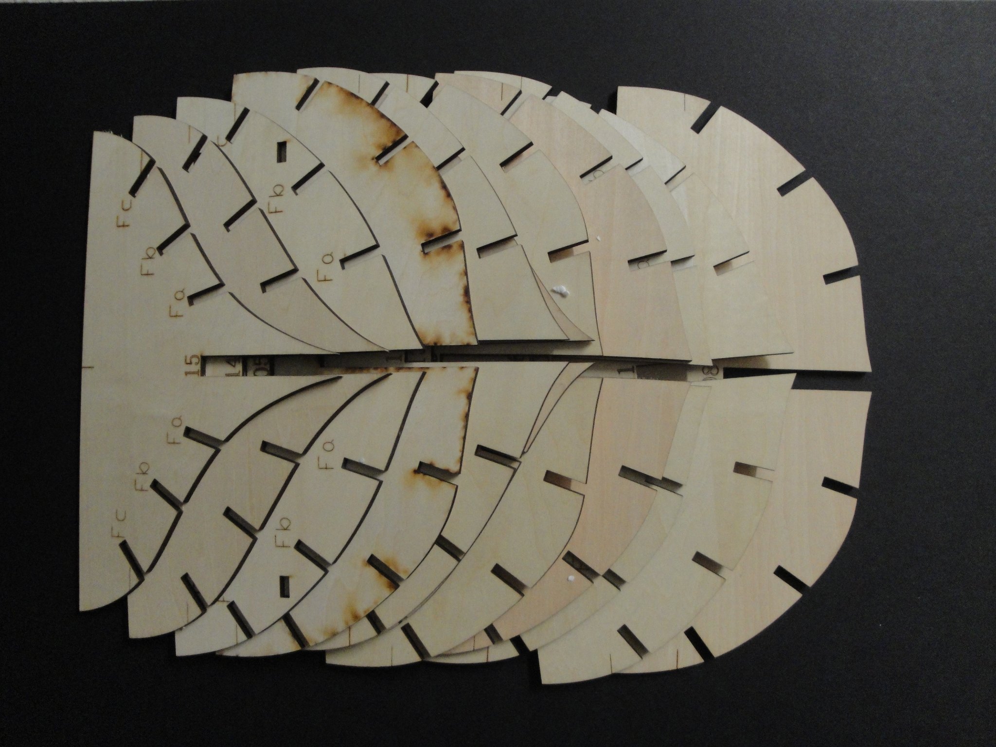
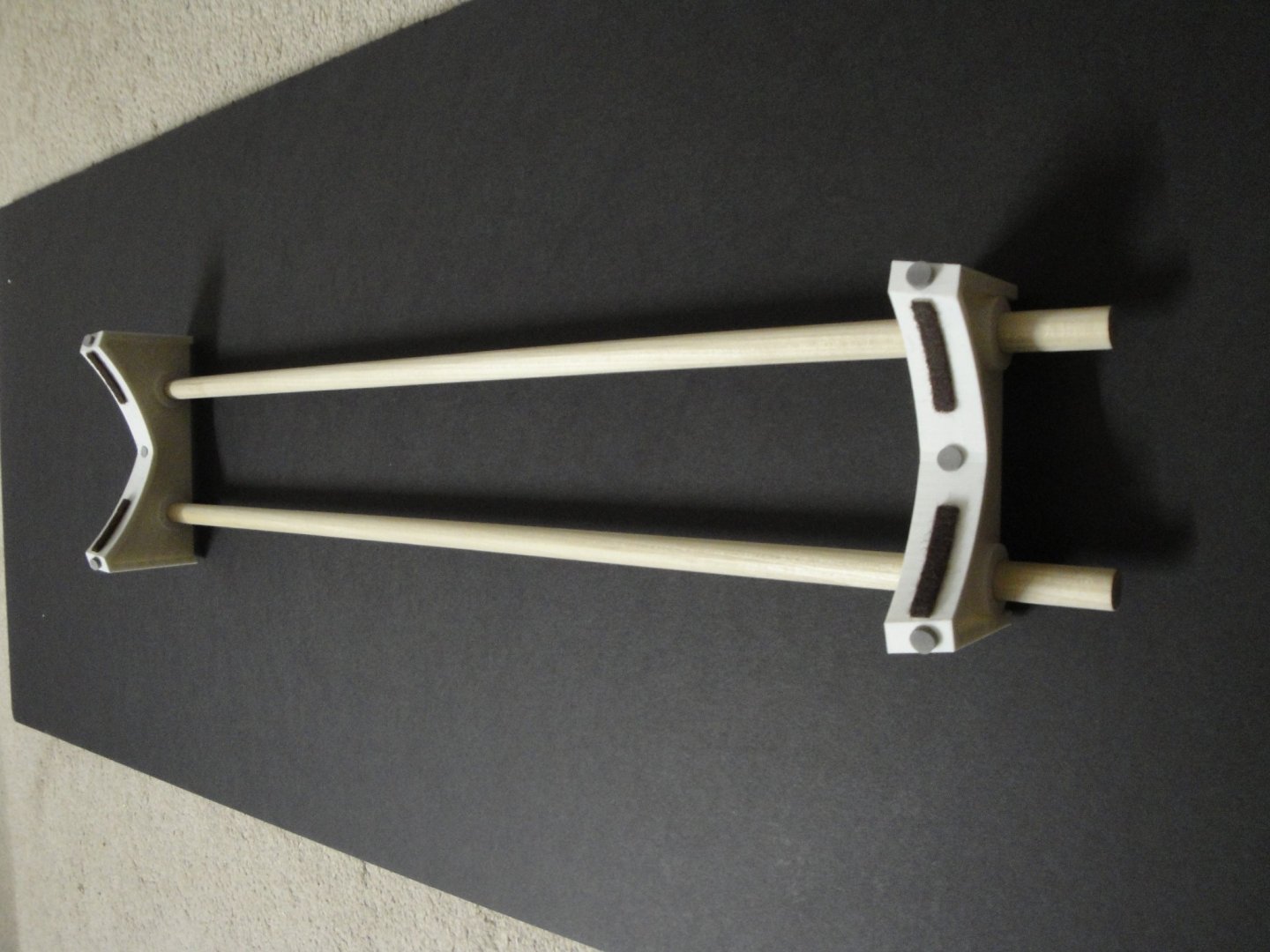
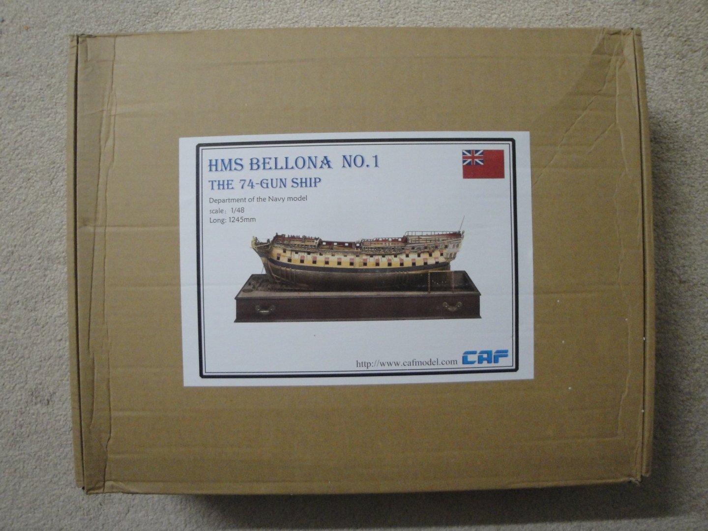
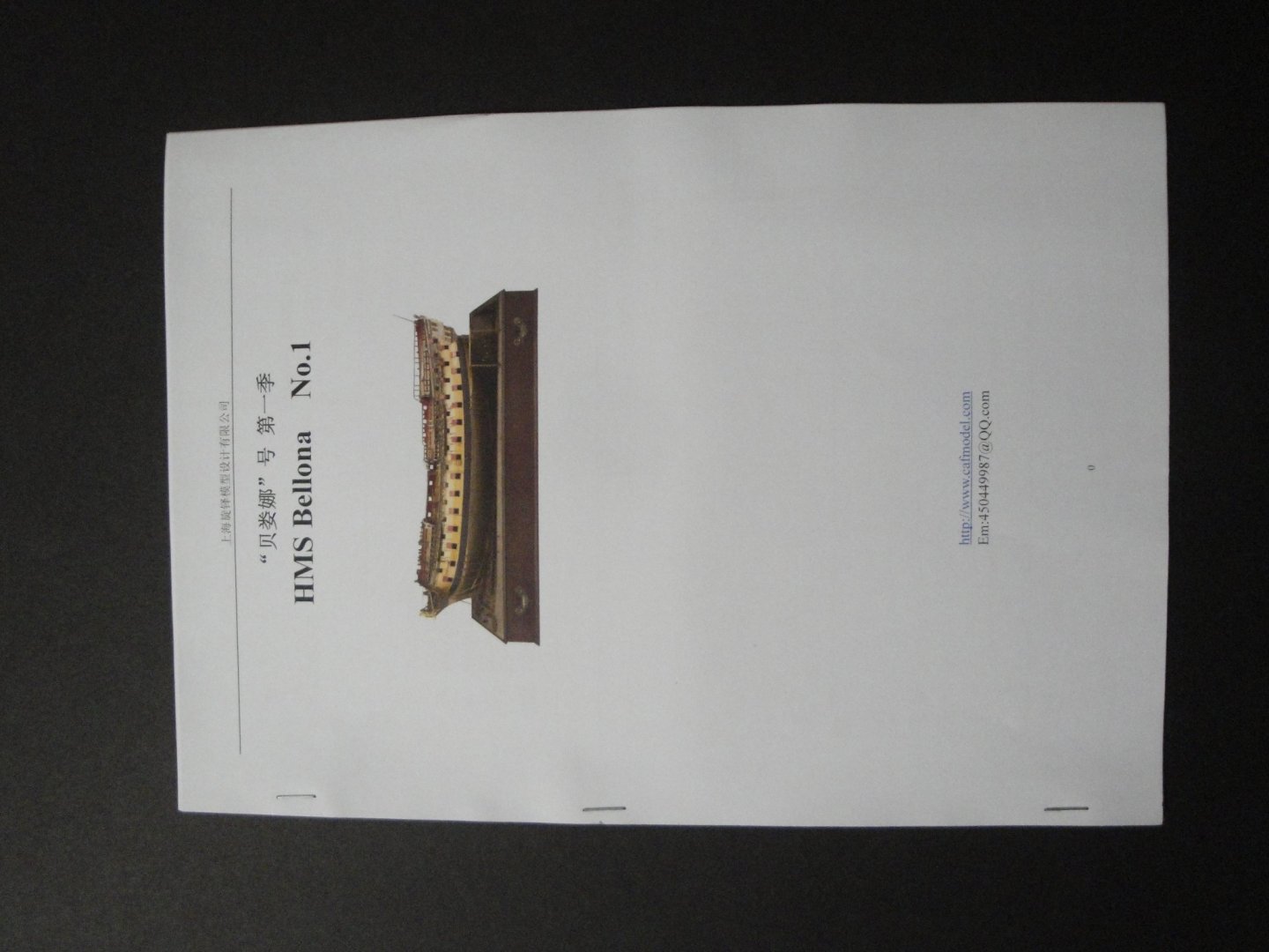
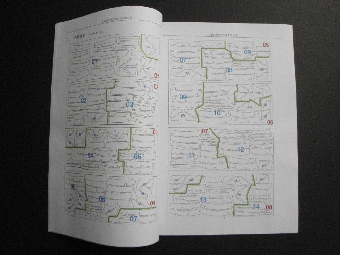
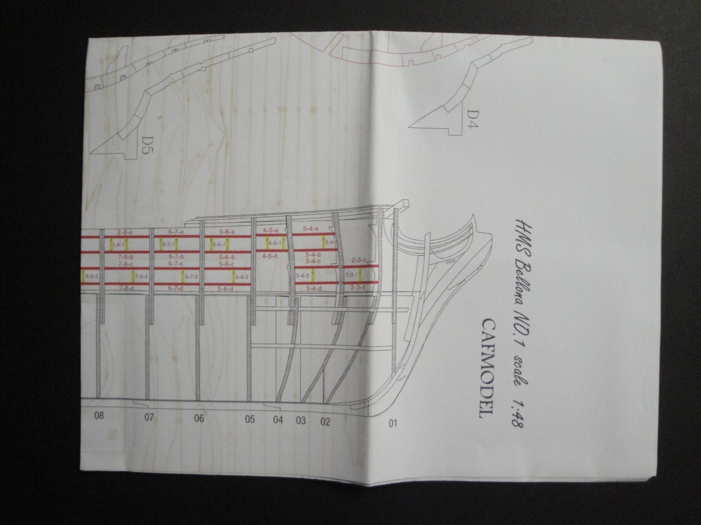
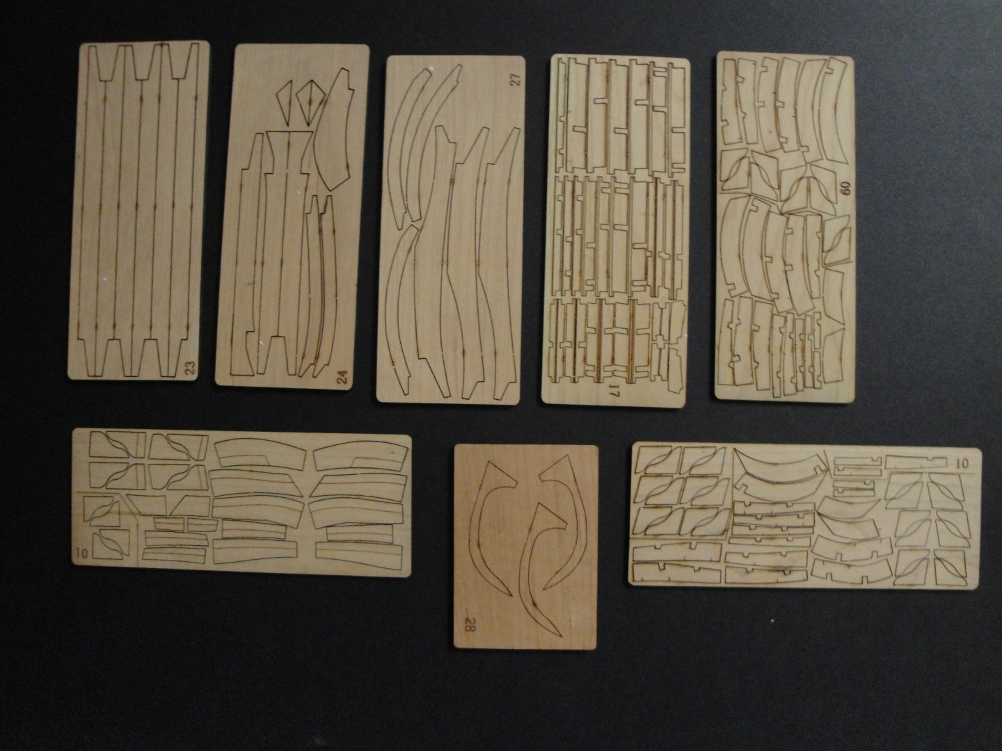
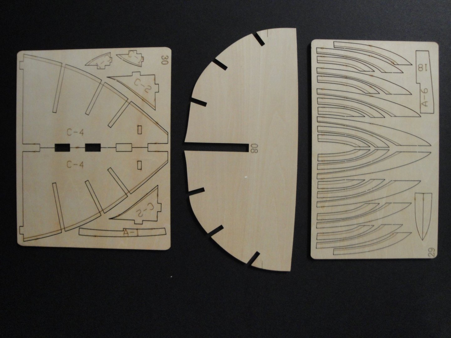
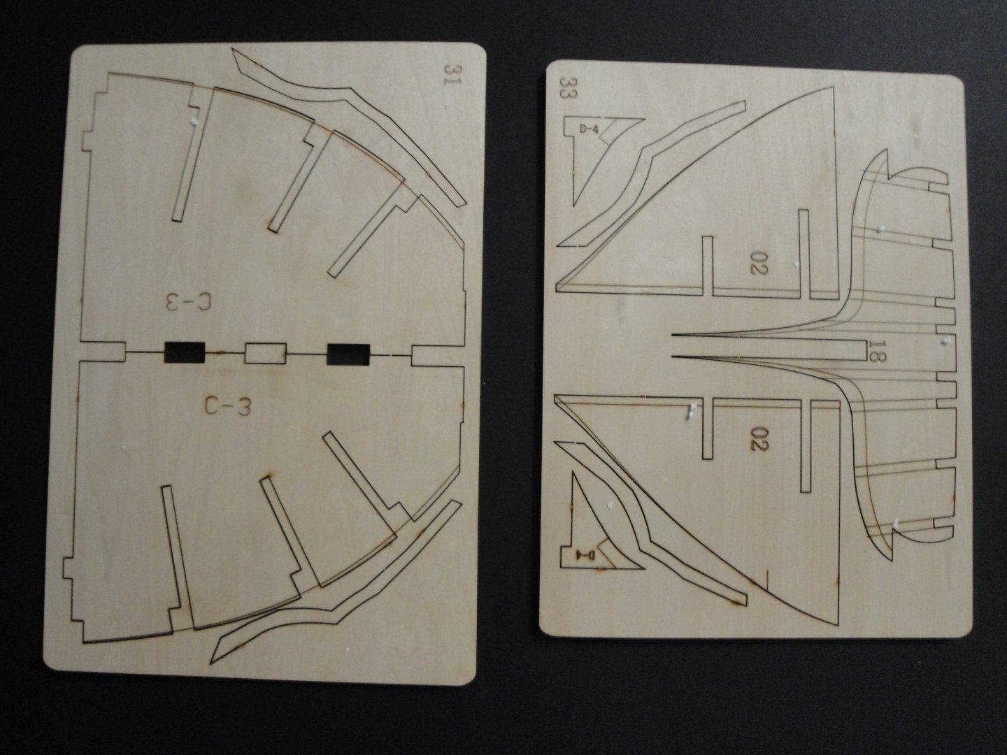
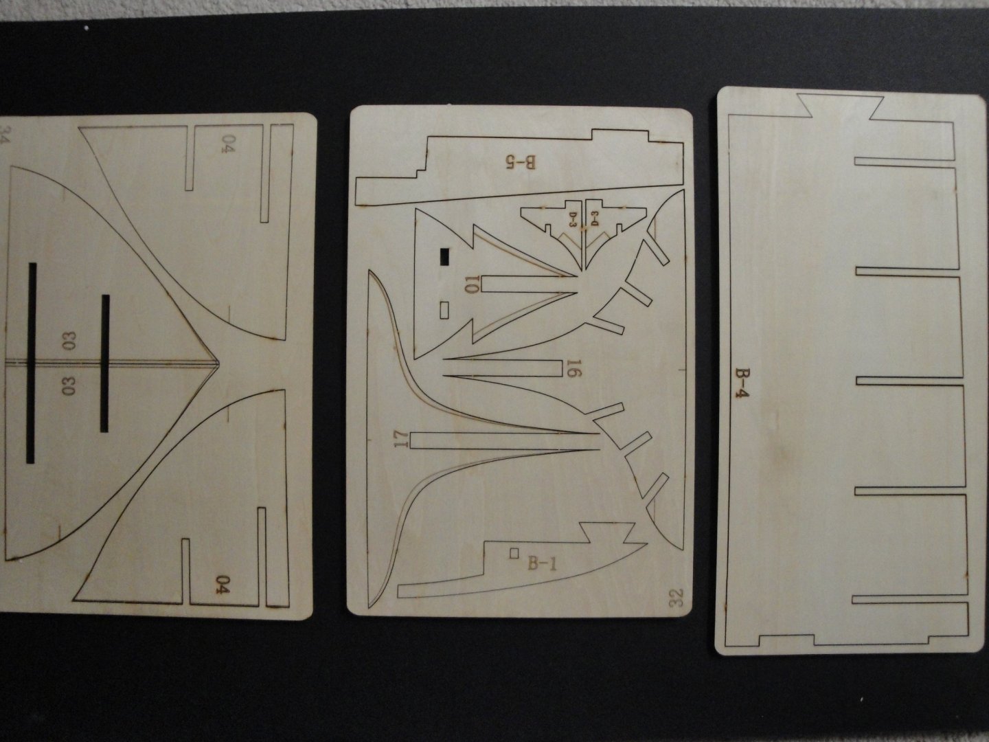
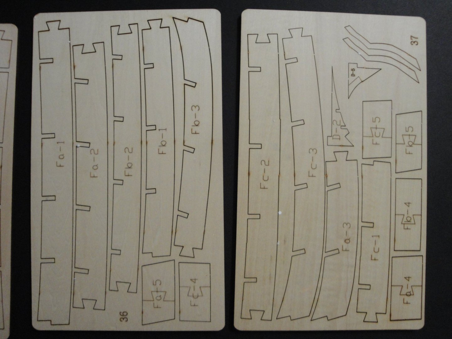
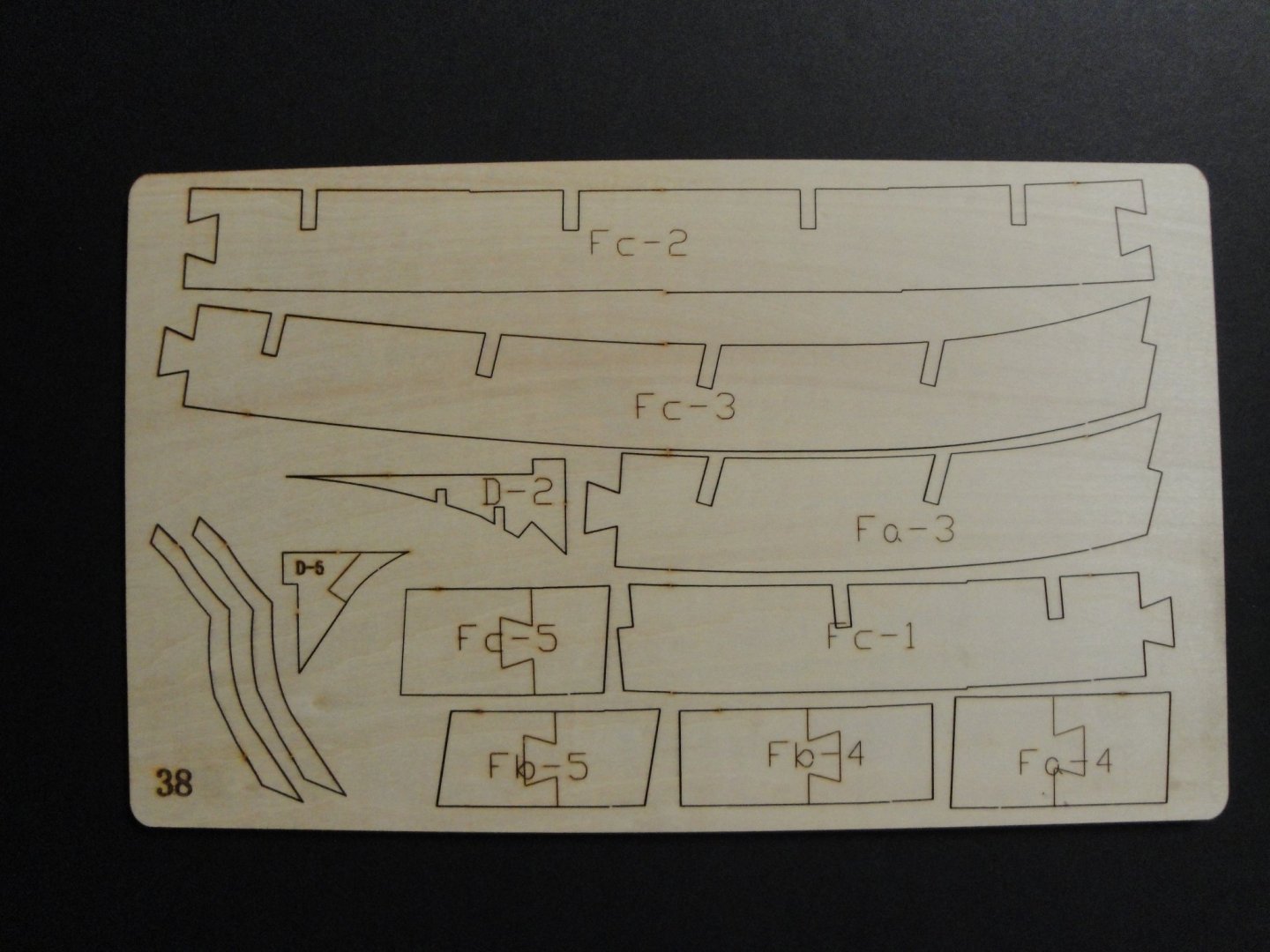
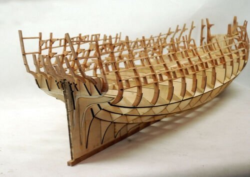
SESSION #1 Well, after breathing plastic and PLA dust for a few months, I needed to go back to the original material, the wood created by our mother Earth. A while back (10 years ago), Chris Watton realized and displayed on our forum an exquisite piece of naval beauty: the HMS Bellona in the scale of 1/72nd. When I saw his model, I felt in love with it and knew that I had to at least give it a try. Fast forward in time.....and CAF Models announced an HMS Bellona in five sessions in my favorite scale: 1/48th. Of course, I am not a fool and know that I will not get even close to the perfection of Chris's model of the Bellona. The Name of that vessel, its prestige and specific missions (Gibraltar, the Tropical and Caribbean Islands) appealed to me immensely. Although I am busy with multiple projects, it felt like it would be nice to try the Session #1 of that model. If I manage to complete it with success, I may order Session #2. I have to say that I like this approach, that allows you to build a large and detailed vessel without investing your 401K in the process. You can attack a model of your choice progressively, without disbursing upfront $2,000 or more. The kit was purchased on E-Bay (milia_3) for $370 including shipping. At first I realized I had made a mistake with the shipping (Free shipping - included in the price of the kit in fact usually means SLOW shipping....), but E-Bay SPEEDPAK did a wonderful job and I got my model in less than three weeks: Ordered August 07, received 08/31. Packaging was excellent with double boxing on top of the CAF box and plastic corners for protection. The parcel flew (thanks God) and did not spent its time in a container stuck in a harbor somewhere. I would recommend that Milia_3 vendor and my experience has been really good with them. So, without more delays, let's discover this great and heavy kit. Inside the box, we find some instructions, a complete list and drawings of all the parts and a full size plan: A lot of wood is provided, with bulkheads of 5 mm thickness and some sherry wood parts: About 44 wooden "sprues" are provided with the kit. It will take a large board to build this monster (1.25 meter long, 30 cm wide) and it should be interesting. Session #1 is basically the skeleton of the hull and nothing more..... I am trying to moderate the enthusiasm of certain readers, here.... Below is what I am shooting for: I still have to make progress on the Flower Class Corvette, and thus the Bellona will not be started immediately. Yves


- 507 replies
-
- 21
-
-

-
-
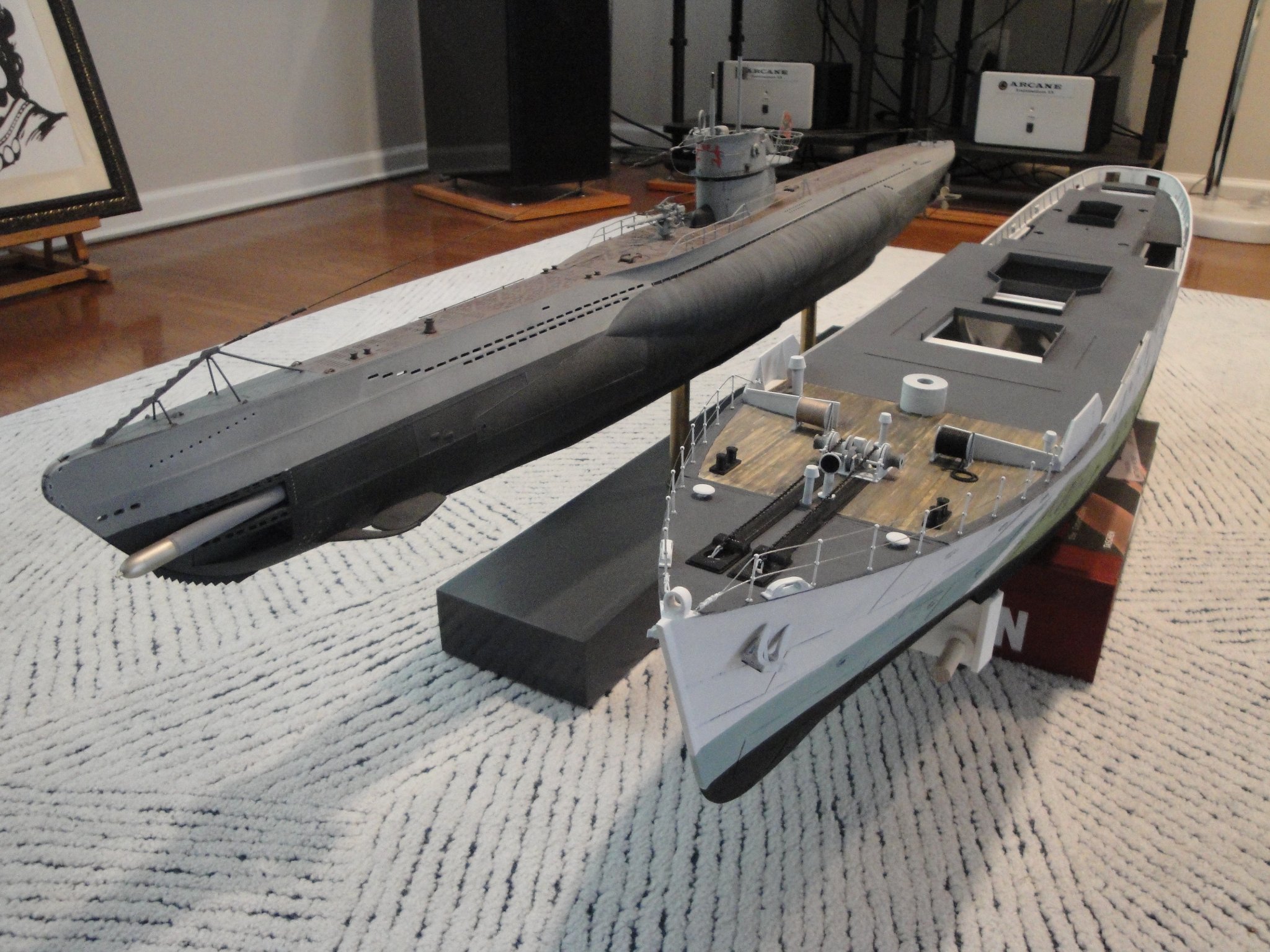
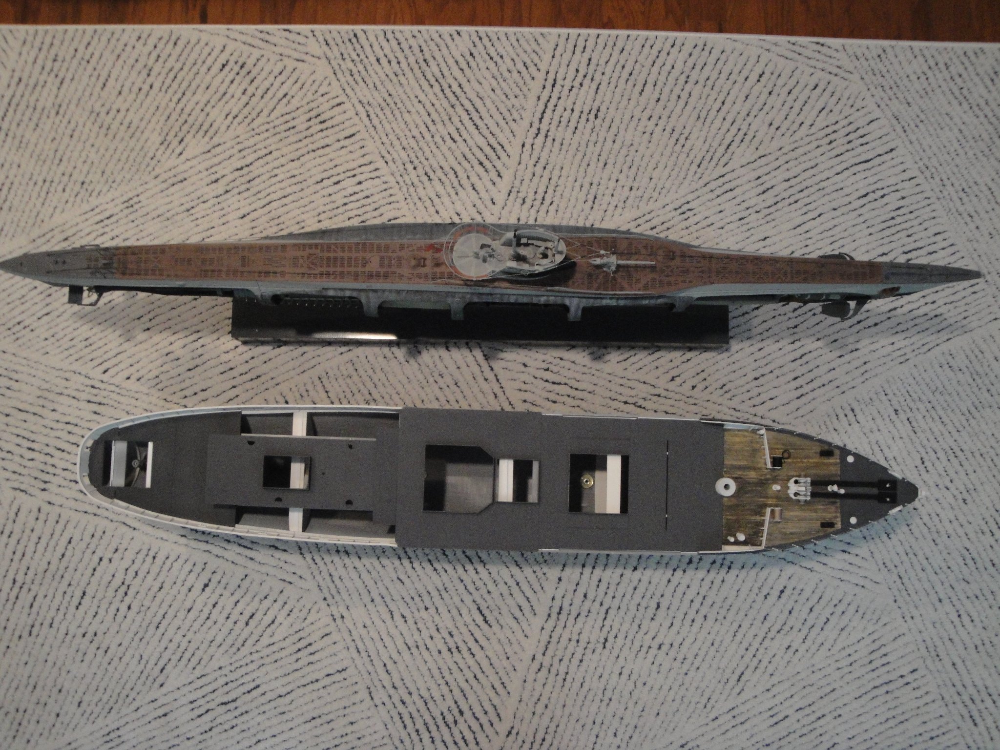
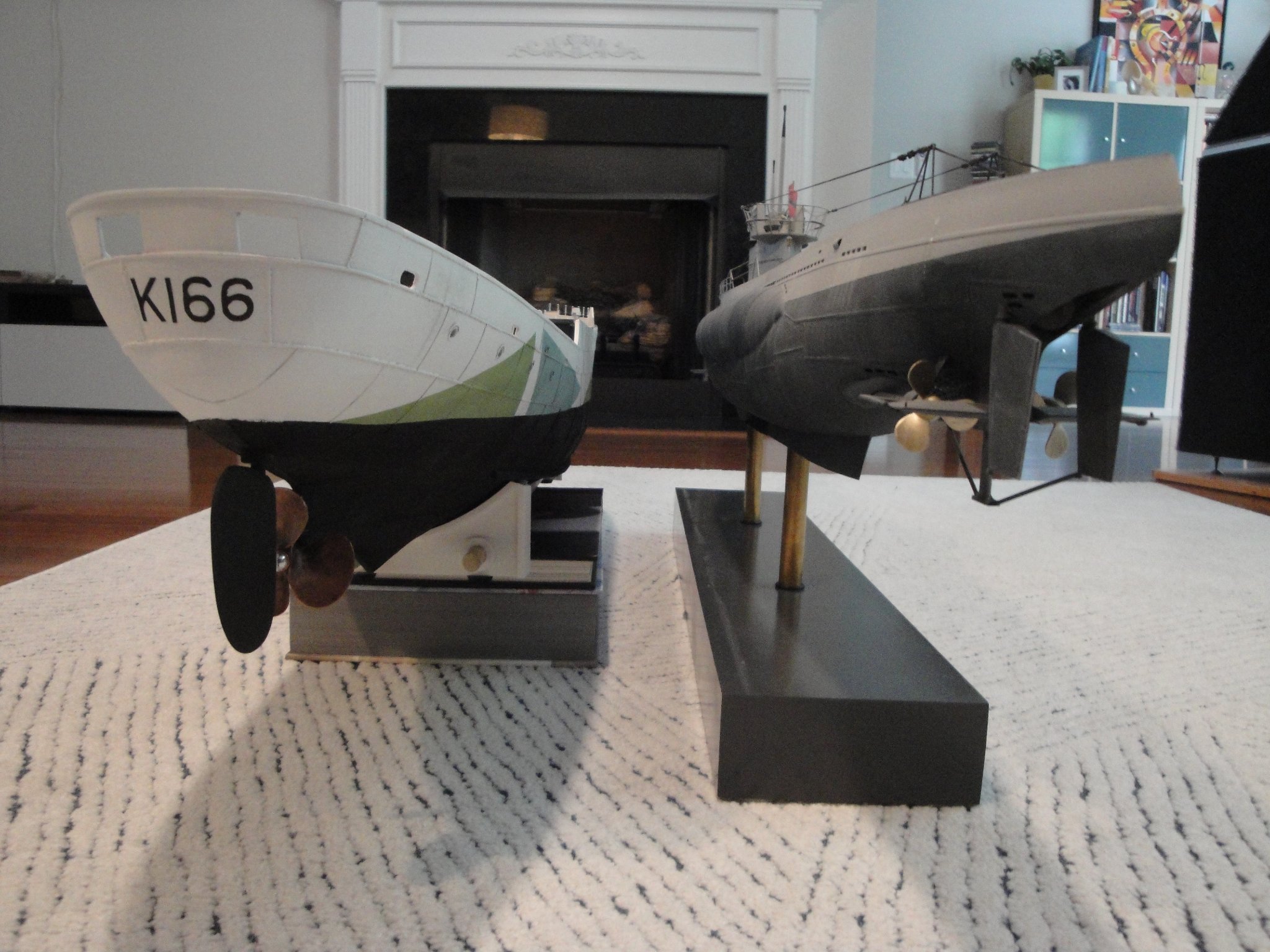
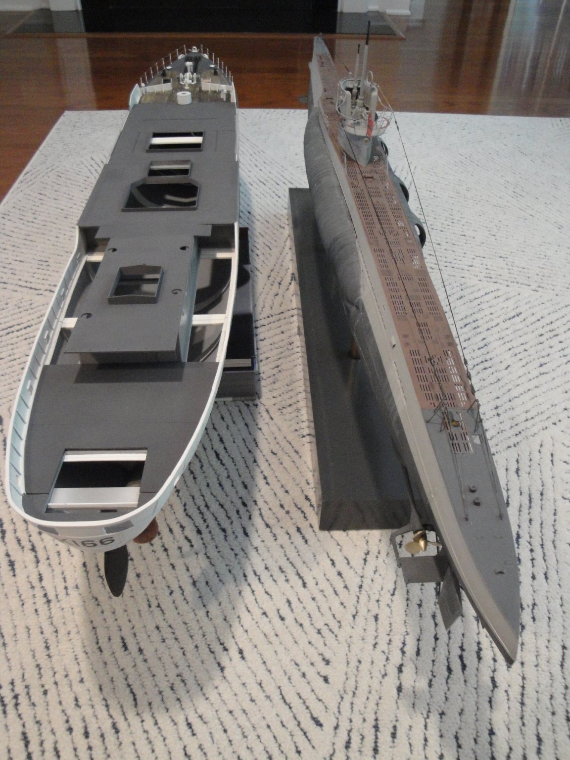
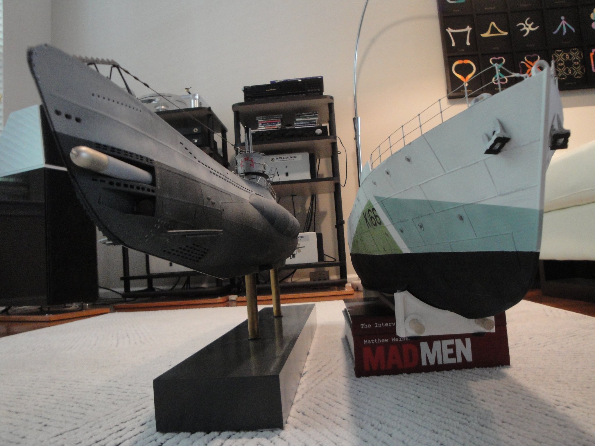
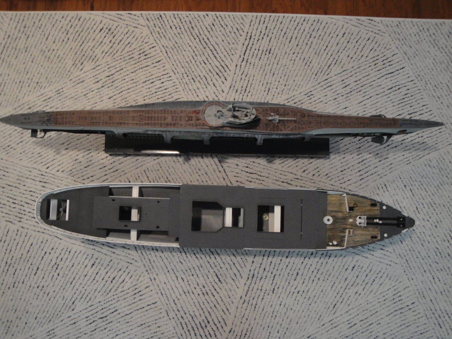
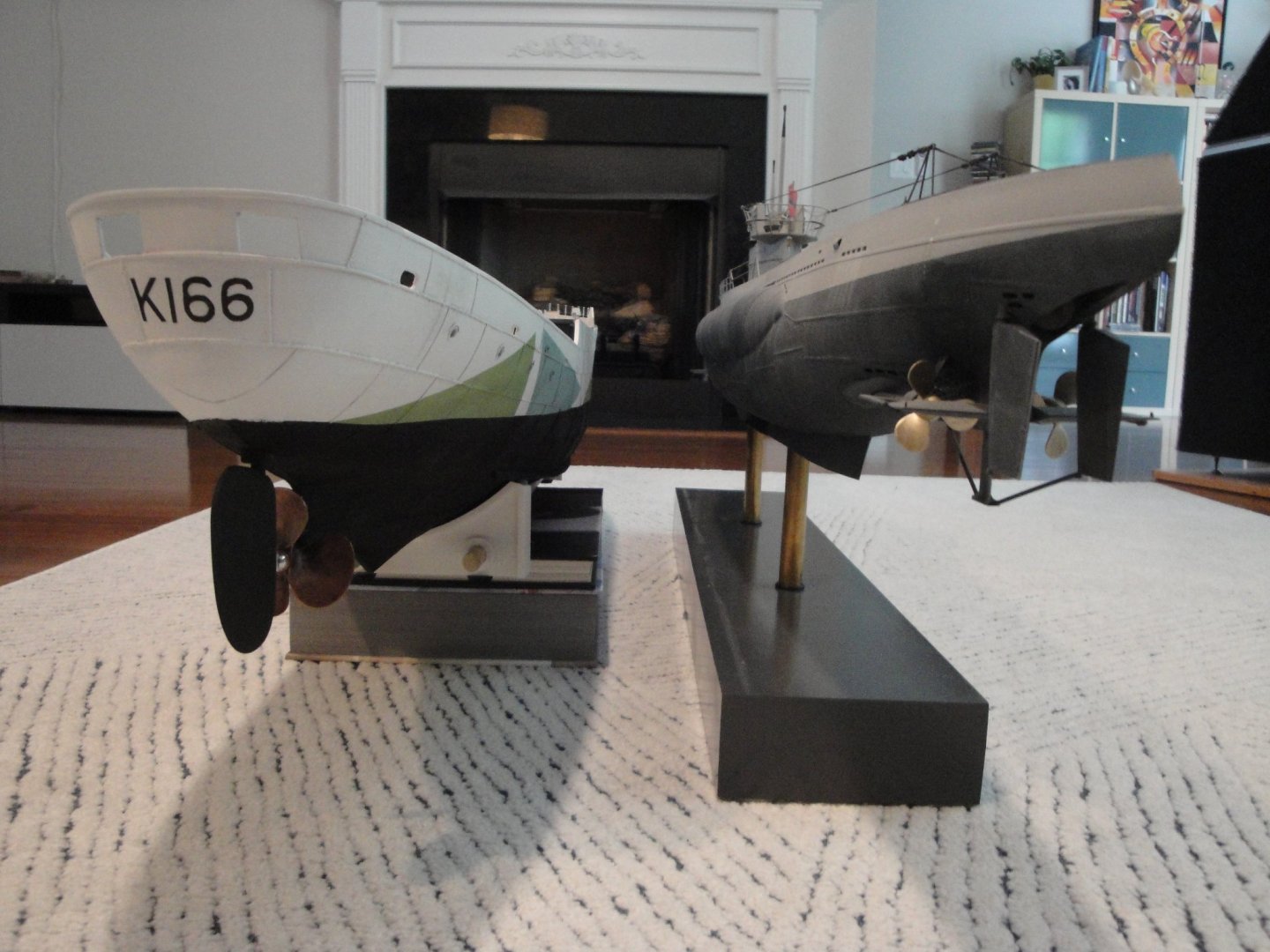
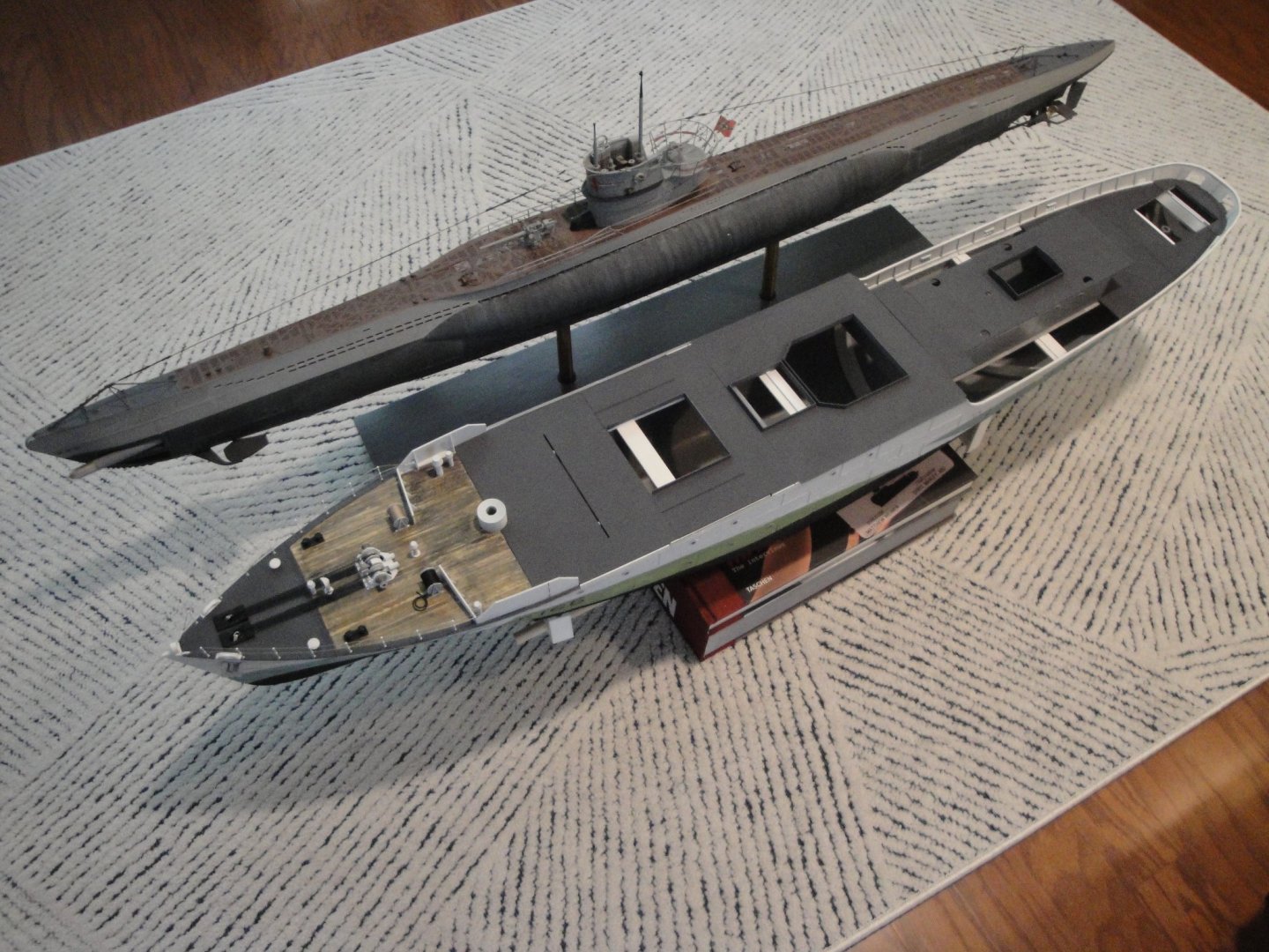
I wanted to publish these pictures which are showing some interesting perspectives. Both vessels are at the same scale 1/48th, and have been the epitome of nemesis: It makes for an interesting comparison. Yves


- 321 replies
-
- 19
-
-
-
- Finished
- Flower-class
- (and 1 more)
-
What a beautiful boat. Nice choice of colors. Yves
- 70 replies
-
- 1
-
-
- Lowell Grand Banks Dory
- Finished
- (and 1 more)
-
Beautiful little boat. Yves
-
Mike, Nothing wrong about asking a question. Yes the virtual kit has all the parts that you see on my log. Every time I add something, it is mentioned. So far,only the stanchions and wood + styrene strips have been added to the parts produced by the 3D printer. I am a newbie in that technology and the only thing I know to do is to modify the size of parts before printing. Yves
- 321 replies
-
- 5
-
-
-
- Finished
- Flower-class
- (and 1 more)
-
I brought them back from France. Wolfcraft is the brand.... I am sure you can find them on this side of the pond...it is all Chinese stuff anyway. Yves
- 321 replies
-
- 6
-
-
-
- Finished
- Flower-class
- (and 1 more)
-
Mike, instead of doing everything with Styrene (which you could do....), why don't you get a 3D printer, purchase the $50 kit, and print all decks, superstructures and fittings? It may cost you less than buying all this styrene material... (not really) and you will learn new skills that may come handy. Parts can be printed to fit your hull: you can play on the width, length and thickness of the decks. It is very easy. Yves
- 321 replies
-
- 5
-
-
- Finished
- Flower-class
- (and 1 more)
-
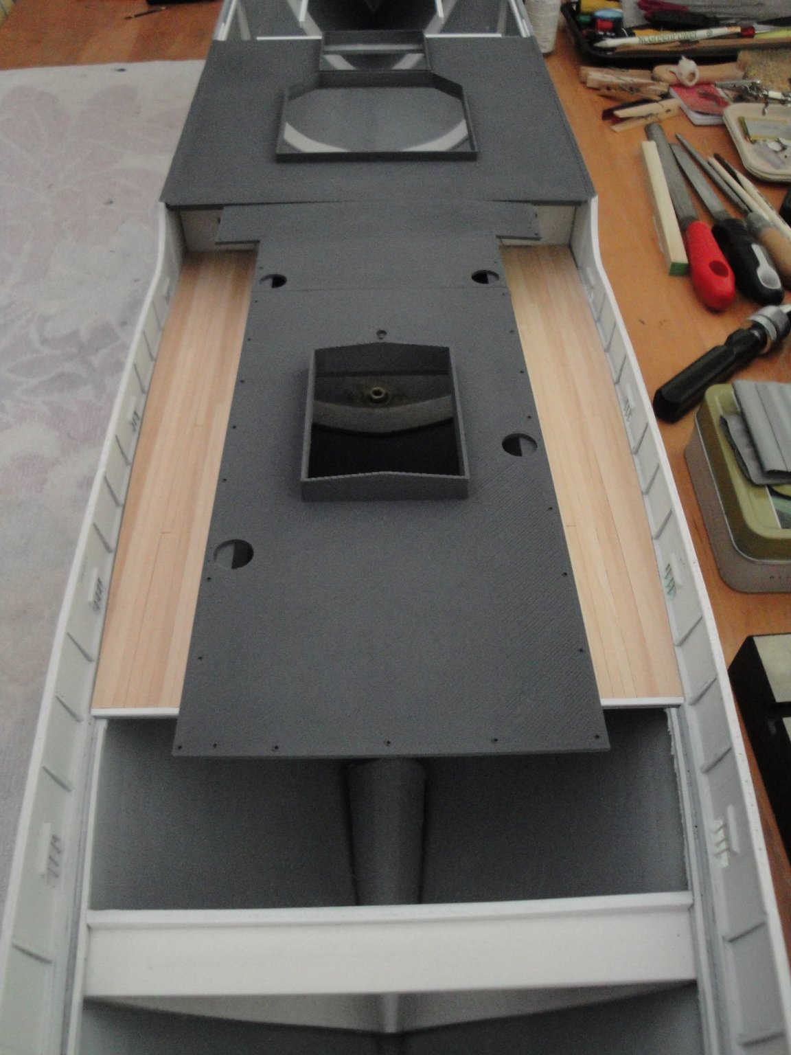
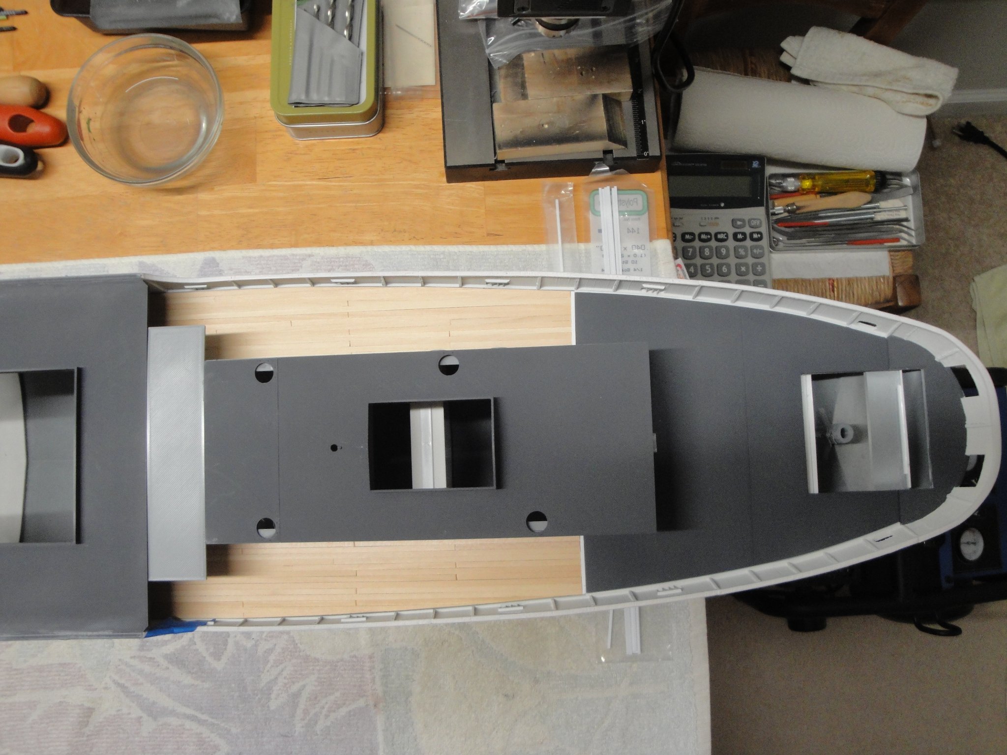
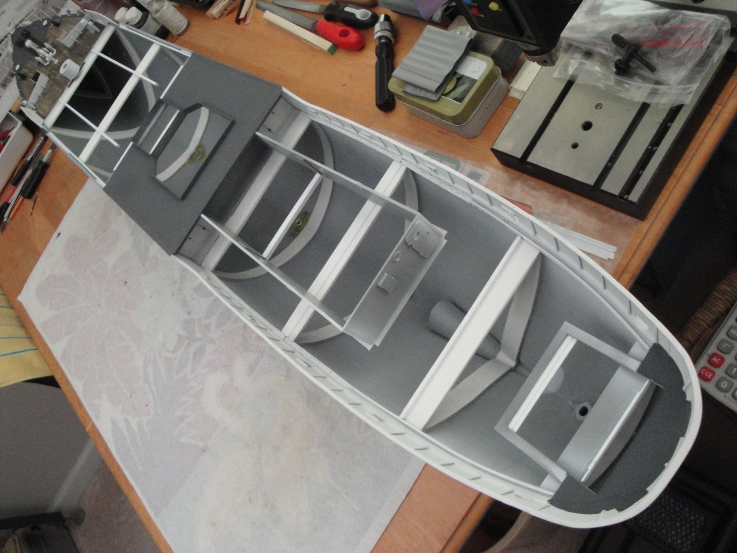
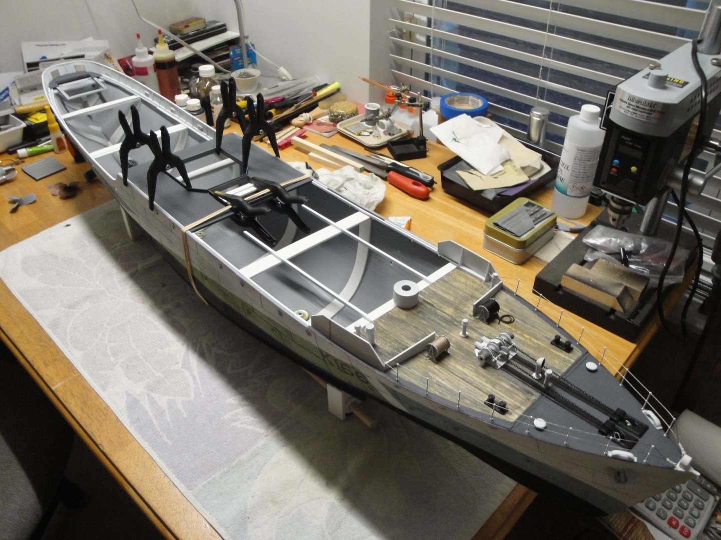
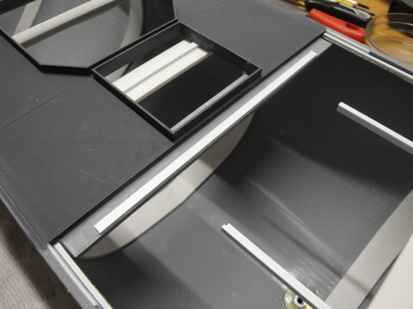
Major milestone today, with the permanent gluing of the floor (Deck #4) of Module 4 on the hull: This piece of deck is very stiff and thick: 3 mm! It brings an additional stiffness to the hull (not that it would need it...). It is glued after careful placement of the forward sections of decks (#2 and #3). Deck #4 holds the tall funnel but more importantly the mast. As such it must be strong and resilient. Note that Deck #4 also rests and is glued to the large white couplings, used to connect the hull sections. The Deck section #3 holds the wheel house and the very top heavy deck. It is made of PLA of only 1.5 mm and may sag a little bit, under the load. To prevent this problem and make sure that the decks #3 and #4 sit perfectly flush, I have added some support in the front of Deck #4. This is made using the "Deck_D_Lip" part with a 1.5 mm strip of styrene on top: With this approach, the deck #3 sits perfectly flat and flush with deck #4. You could glue all the decks at once and be done with them. But then, working on each independent section becomes a challenge as this hull is large. I'd rather work on a small section at a time and then place it on the hull, once it is finished. Yves

- 321 replies
-
- 10
-
-
- Finished
- Flower-class
- (and 1 more)