SJSoane
-
Posts
1,655 -
Joined
-
Last visited
Content Type
Profiles
Forums
Gallery
Events
Everything posted by SJSoane
-
 Thanks, druxey and Mark P, I think we have resolved how this complex junction is managed. The Bellona sheer drawing shows a larger radius curve at the lower, aft corner of the wale, and from the way things are lining up on the hull, I think it is because of the natural curve of the plank immediately below the wale. At least that is how it seems to be emerging as I try to fair these pieces. druxey, I see your wale does tuck under at the lowest, aft corner; this is reassuring, because mine really looks like it wants to tuck under. Mark P's image shows a wale more straight up and down. I am sure this has entirely to do with the particular geometries of the under body for each ship. The famous architect Lou Kahn once asked, "what do you want, brick?", to determine how to use it according to its own inherent nature. I would apply this to wales at this point: "wale, how do you want to follow the natural lines of your hull?" Apologies for weird thinking... And by the way, beautiful model of the Resolution, druxey! Mark
-
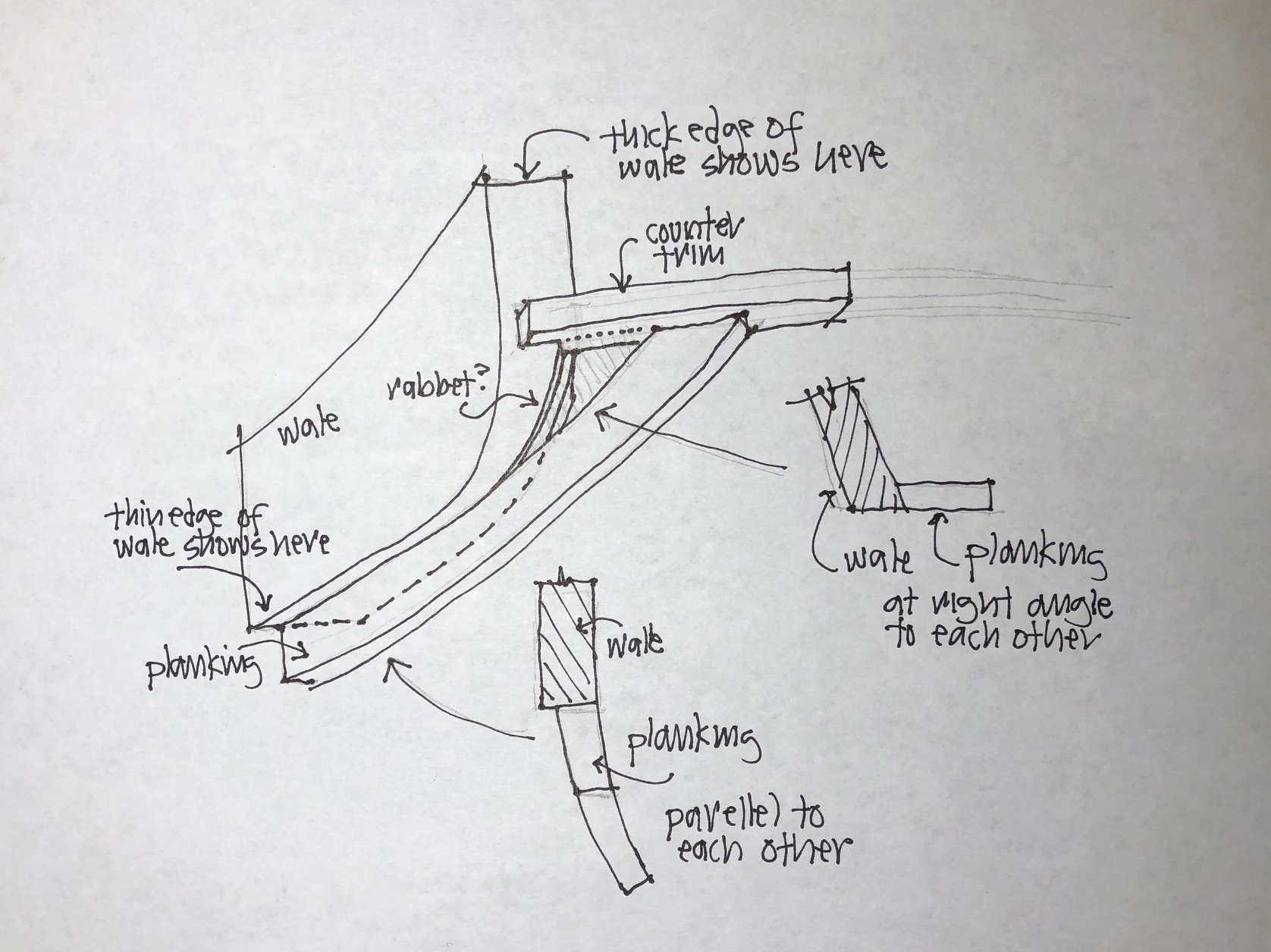
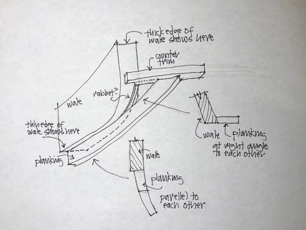
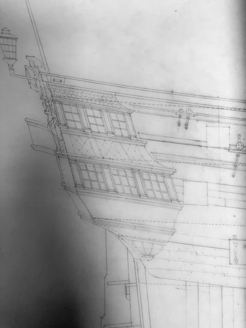
Thanks, Mark, this is a very helpful view. I think it confirms where my hull seems to be taking me. The wale is revealed at full thickness at the aftmost end where it is vertical and hits the lower counter, but shows only 3-4" along its lower edge where the lower planking is parallel to the wale and abutting against it. The triangular plank we have been discussing looks like a transition piece, itself standing at right angles to the wale at the top, but allowing the lower planking to come from parallel to right angles to the wale as it bends around the corner. The attached drawing shows how perhaps a rabbet would provide a landing for the small triangular piece, where the rabbet would be narrow at the top and increasingly wide at the bottom. This is a difficult drawing to visualize; it tries to line up with the perspective of Mark P's image above. This would be a fairly elegant solution to reconciling all of these at this corner, as best as one might expect given the complexities. Mark
-
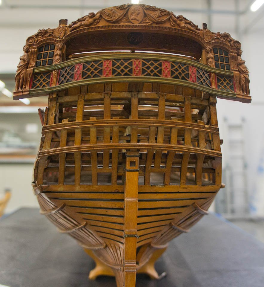
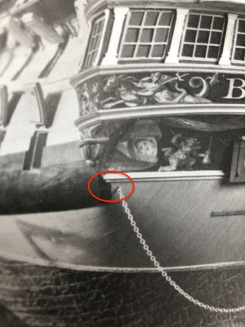
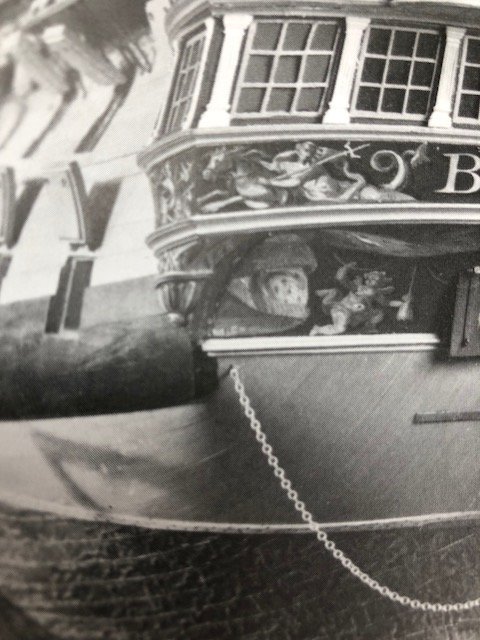
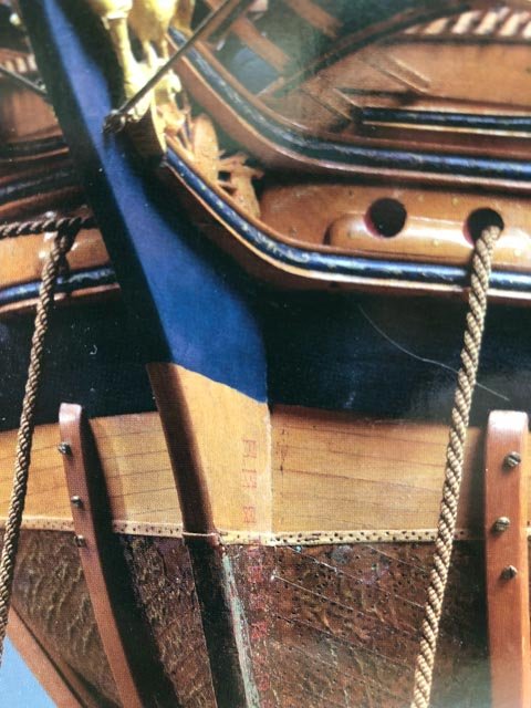
hi druxey, Well spotted, I never noticed that. Could it be the little corner of planking just above the chain circled in red below? If so, the wale in the first model has wrapped much further around the corner than in the second model. In the second model below, the triangular plank hits the inner side of a much thicker wale at an obtuse angle, and could not be confused for a smooth continuation of the wale plank as in the first model. Mark
-
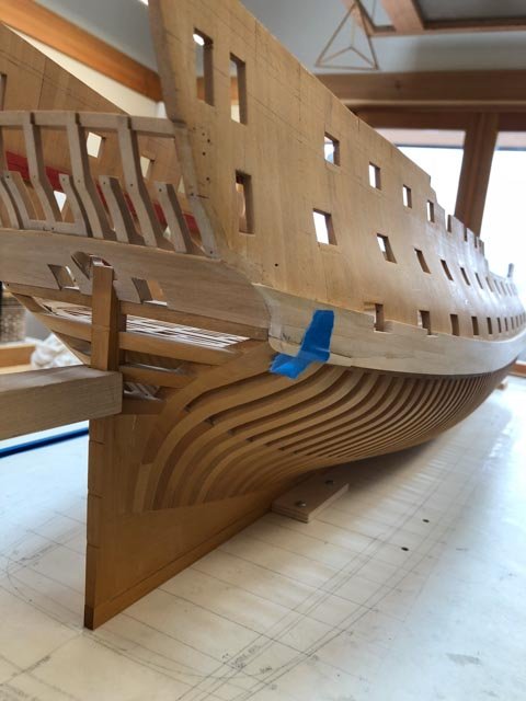
Just for fun, I looked again at the photos I took of the 1st Bellona model. It shows the lowest, aftmost plank of the wales curving around under the stern, like the planking presumably would do below it. This is not consistent with the original Admiralty sheer plan, nor with the 2nd Bellona model with the copper sheathing. I will have to assume that this was a modeler's convenience, dealing with the reality of skeletal planking in this portrayal of the ship. Unless anyone has seen a wale curve under the counter like this. Mark

-
Amalio, Outstanding project, some of the very best craftsmanship I have seen. You are a source of inspiration! Mark
-
Thanks, druxey, that confirms for me that I am on the right track. This is definitely a spot that is less than gracefully worked out, in the big scheme of design. I think a lot of fiddling had to go into reconciling the various parts that intersect here. I have noticed that on some other ships, the lower edge of the wales align exactly with the trim across the lower end of the counter, making the junctions below this easier to reconcile. Look at Siggi's nice junction at this spot, for example, on the 1745 Establishment ship. But for some reason, the Bellona drops the wales partly below this, causing them to run partly into the counter, and partly into the very complex compound curves below. This has to be the point where the construction crew asks "what the [insert favorite explicative here] was the shipwright thinking here?" Mark
-
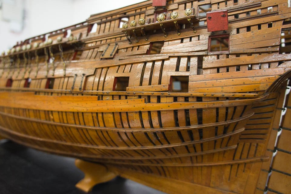
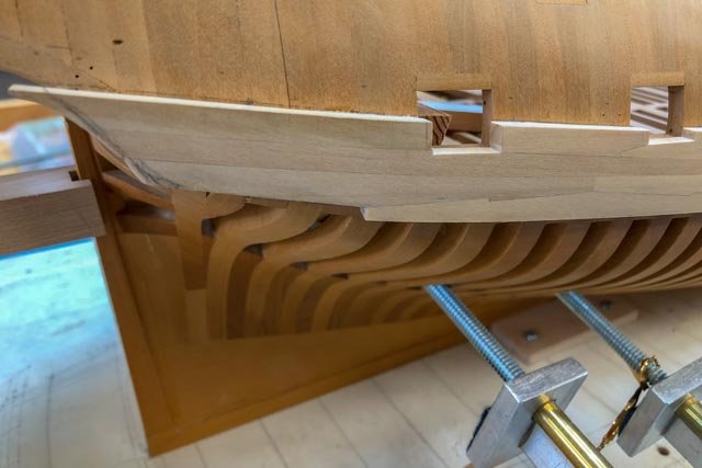
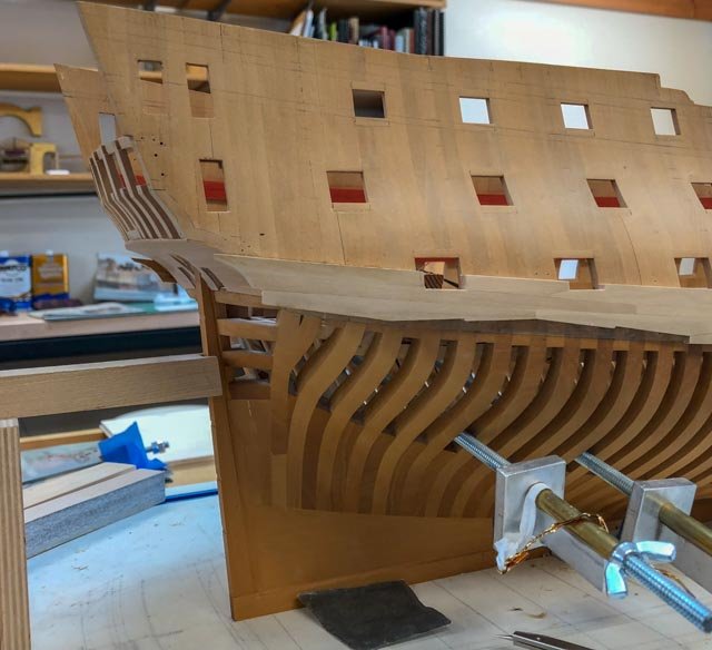
I spent a happy day carving the last plank. However, in trying to make everything fair together, I noticed that a gap appeared to be forming between the curved end of the wale (see the curve in the drawing below), and the hull framing itself. I thought I had messed up my framing somehow. But then I looked at the photo of the second Bellona model below, and noticed that the wale shows its full thickness along the counter and along that lower curve, but not on the lower edge. The planks are clearly coming around that curve, and then tucking in behind the wale at the curve itself. If this were not the case, the short little planks at the curve would be covering up 4 inches of the wale, which it does not appear to do. So, I am assuming for now, until someone tells me otherwise, the wale does indeed stand away from the hull at that curve, enough for the lower hull planking to die into it. I have had a devil of a time visualizing what is going on at this junction... Mark


-
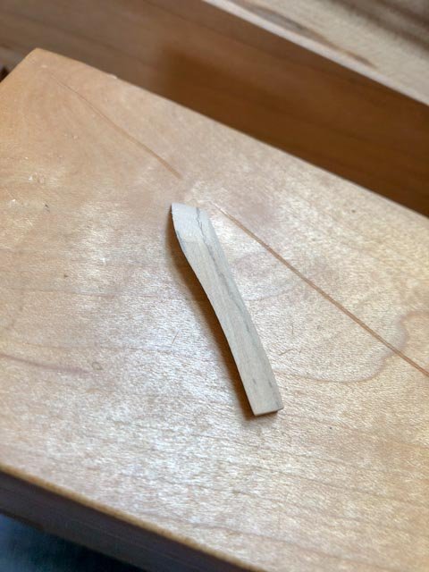
Thanks, Gary, for the comments. It is kind of hard to realize now, but I learned to draw before CAD was invented or at least used in architecture offices. I am a dinosaur! Gaetan, I haven't checked my family tree lately....🙂 It took pretty much all day, but I got the second to last plank in on the wales. It has a very sharp twist athwartships, and a good bend aft. I could not get a clamp on the end for love or money to steam it to shape. And I could not imagine a former that would deal with the springback accurately. So I fayed a double wedge shaped piece onto the inner surface, fitted it to the hull surface, and sanded down the outer surface to parallel. The join is on the under surface of the wale, where hopefully no one will ever look and the black stain will cover it (as long as none of you give away the secret). The final piece is even worse, and I can't visualize yet exactly how it lands and what its aft edge looks like. The second Bellona model shows a sharp corner at the lower, aftmost edge (see photo), but the sheer drawing shows it gracefully rounded. I will put a big block against the location tomorrow and start carving until it looks right. Mark
-
I will add to the other comments the same compliment: those sculptures are beautifully done! Mark
- 1,035 replies
-
- 8
-

-
- royal katherine
- ship of the line
- (and 1 more)
-
Hi Gaetan, I see online that the $180,000 for the Canon 1200mm lens is for a used lens. I wonder what kind of a sailboat we could get for $180,000... I agree on the exceptional value of a batten for aligning planking. I got the idea from Gary shipwright after looking at his successful wales installation. And I can see now from him and from you the value of the batten for important pieces like the mouldings and the channel wales. Mark
-
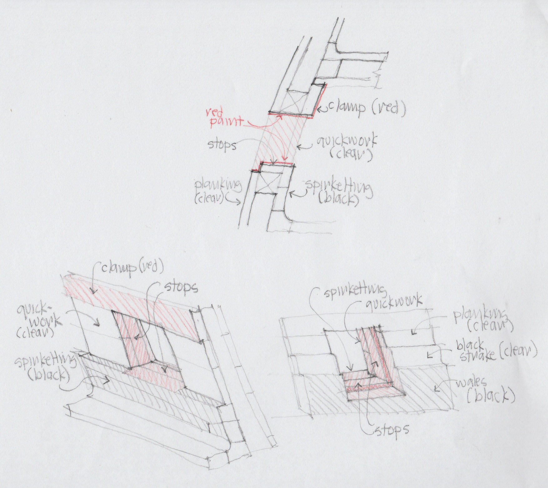
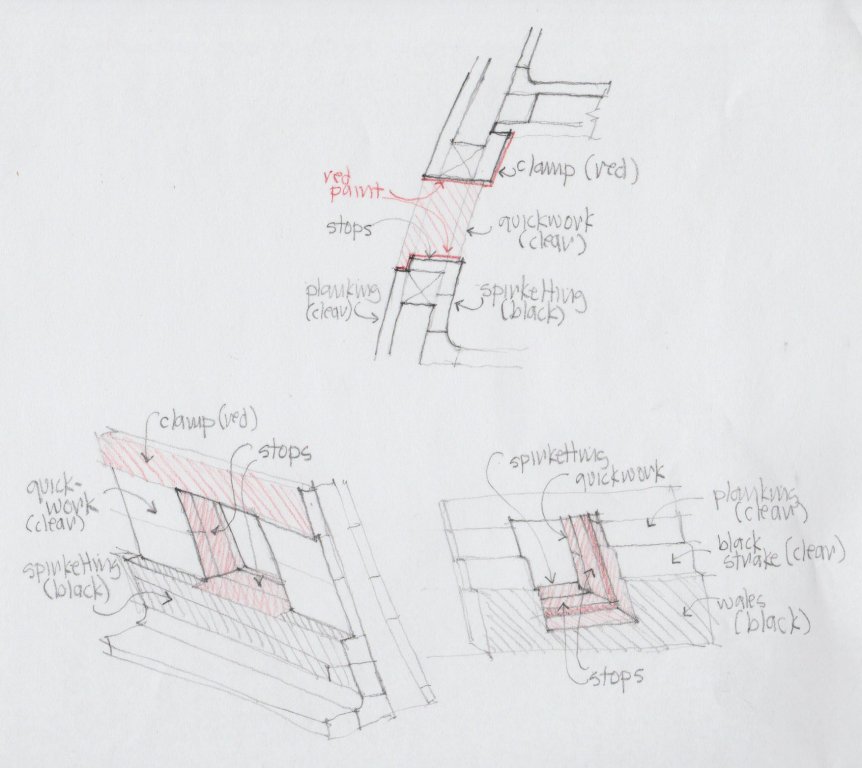
Thank you, Amalio, for your kind thoughts. I have mostly learned from books and especially from the great modellers on this site. And a lot of mistakes! I am having to carve/shape the last two planks, and while taking a break from this, I looked more carefully at where paint/stain will meet edges and surfaces around the gunports. I have drawn a little sketch to think this through. I was surprised to see that the red paint comes over the top of the spirketting, meeting the black of the spirketting on a scribed line; and where the wales cross the last two gunports, I will have the black of the wales meeting the red of the gunport on the edge between the two, on the same piece of wood. And, the edges of the clear outboard planking will meet red paint on their outside corners at the edge of the port. These are the real test points of whether stain will work, or whether I need to edge these points with paint matched to the red stain elsewhere. Now I know what my test pieces need to look like. Mark
-
Hi Gaetan, That is quite impressive a range. It is hard to see if the extenders degraded the image in comparison to the lens by itself, or compared to a greater telephoto lens. Do you have a recommendation on the best quality? Mark
-
Hi druxey, Yes, that is my anxiety about the ports. I have really liked the red dye on already installed parts (like in my member picture), and I wonder if I can color match an acrylic paint just for the gun ports? I will track down Humbrol matt 25, and also pick up a few samples of red paint to see how they might match to my existing red dye. I long ago bought a range of Floquil reds and blues, but alas not enough of any one to complete the project. That is what I get for taking so long on this project! Mark
-
Ed, what an incredible essay into masting and rigging. The craftsmanship could not be better. Small question, the lashing for the studdingsail booms seems quite fiddly when one thinks of someone up there trying to unfasten the knot at short notice. I would have thought they would have developed a quick release device, or a cleat allowing an easier tying or untying process. I am sure you have done your historical research, so this is just an idle reflection on their design thinking. Mark
- 3,618 replies
-
- 5
-
-
- young america
- clipper
- (and 1 more)
-
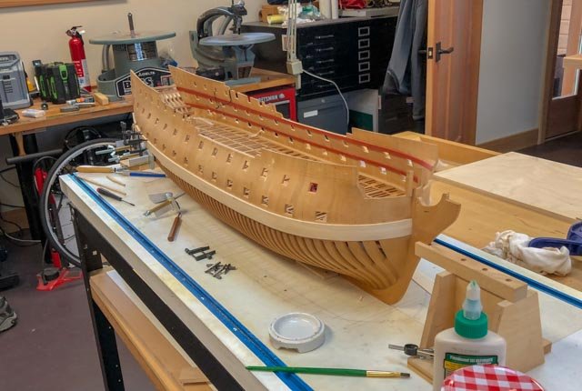
Work proceeds on the starboard wales, with only three planks--the most twisty of all--to go. While the uppermost one is steamed and clamped against the hull waiting to dry, here is an update. I have decided to mock up a single gunport and adjacent wales, to see how I am going to manage controlling the red stain around the port, against the plain external planking and the black wales. Like the black wales, I am concerned about the red stain around the gunports running into the grain of the adjacent planks, and only a test will tell me. I did have a little more success using the Transtint black dye mixed into the urethane clear finish. Rather than dealing with a watery liquid like shoe dye or ink, this allows me to pad on a tinted gel. And it has the same level of matt as the uncolored finish. I will also experiment with airbrushing the blue acrylic paint onto the stem, and also onto the upper works where the friezes will go. That should help me keep a clean line. I am thinking about ordering the Caldercraft Admiralty paint "French Blue", unless someone has had a bad experience with this paint, or thinks it is not the right color. They are supposed to match the colors around Nelson's time, which is almost a half century after the Bellona; I can only assume the blue color would not have changed, for lack of any further evidence. I have only the second Bellona model to go on, for a match. Mark

-
Thanks, Joe, for your kind thoughts. Having just recently retired, I am enthusiastic about having more time in the shop, and yet I have an increasing awareness of more years behind me than in front of me. It helps keep me focused on making stuff as long as I can! Mark
-
Thanks, Mike, this is very helpful, and a very beautiful model. This is a good reason to visit the Hamburg museum, which I have not yet had the opportunity to do. Mark
-
Thanks, Jason. I have looked at those photos for years, and I always assumed the stem was the same as the wales, and the bluish tint was just a different light falling on the black vertical surface. It does appear now to be the same blue as is seen behind the friezes.
-
Last night I was looking at various images I have of the Bellona's bow, and suddenly realized that the paint on the stem is dark blue, not the black of the wales. This changes everything! I will need to paint the blue with opaque acrylic paint for the friezes, and I can do the same for the stem. So I can cut in a clean line with paint, rather than staining black and worrying about the stain running. It never hurts to look at the sources again...

-
Sherline mill and lathe questions
SJSoane replied to Landlubber Mike's topic in Modeling tools and Workshop Equipment
I mounted my lathe and mill on laminate MDF as Doug just showed; nice surface for cleaning up. And after previously experimenting with tools in drawers, I more recently tried mounting them all on the wall, where I could see them all. I prefer this method now. Mark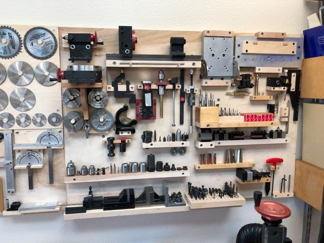
- 24 replies
-
- 13
-
-
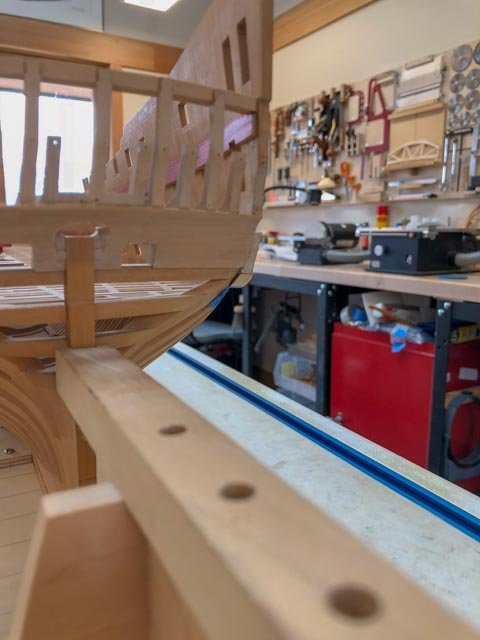
ah, hah! So forget the tape, which I was finding difficult to match up to the scored line anyway. I'll try it.
-
Hi Gary, Nice! I have always been fascinated by the shuttle. I have an airbrush, and I think it is time to dust it off and try it with stains. Do you remember what you painted your wales with? They look great. Mark
-
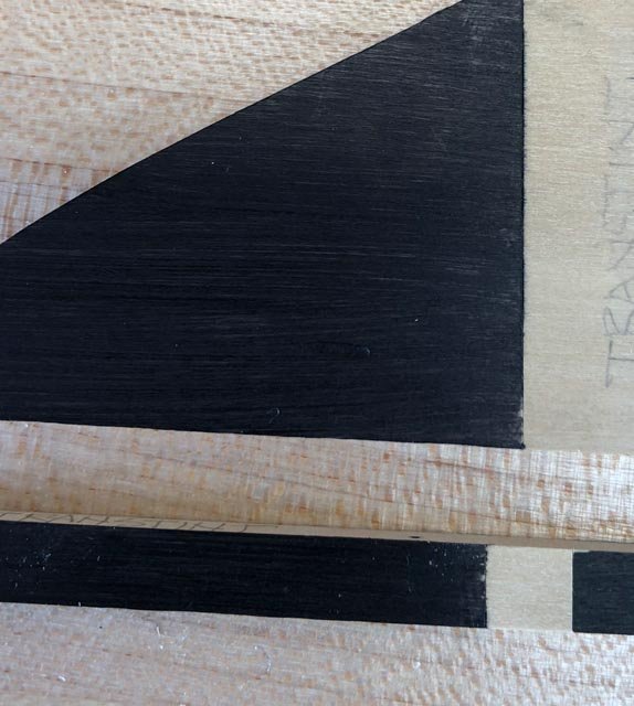
Hubac'sHistorian, that is worth trying; I will experiment with that, including the idea of using an airbrush. With good masking and the hull turned upside down, an airbrush might do the trick. Meanwhile, I tried two other finishes, that are getting closer, but not quite yet. I scribed very deep lines with a scalpel, which seemed to help. Then I taped with Tamiya tape burnished down. The one on the upper left and lower left are both Transtint black dye mixed into General Finishes gel topcoat wipe on urethane, which is my main finish for the natural wood. This was put on with a rag. The one on the lower right is the Speedball black ink used by Ed Tosti for his Naiad project. I used a paint brush. In another test, the Speedball also ran, so I am not sure why I got such a clean line on this experiment. Before risking the entire hull, I will play with these a little more until I get reliable results every time. Best wishes, Mark
-
HMS Naiad 1797 by albert - FINISHED - 1/48
SJSoane replied to albert's topic in - Build logs for subjects built 1751 - 1800
I echo Ed's comment. Beautiful project. Mark -
Thanks for the likes, and thank you Paul and Albert for your kind comments. Thanks Greg and druxey, for thoughts on the staining/painting issue. I don't think I will have problems on the wales on the upper side, because I can paint/stain before installing the black strake, so I can get a clean line there. And the lower side I think I can cut in with masking tape and an incision, because the wales are physically a separate piece from the hull. I take your point, Greg, about errant stain; I will probably turn the hull upside down and mask the entire thing except the wales before commencing. The challenge is on the stem itself, where the paint edge simply stops on the same surface as seen in the Bellona photo above. I looked back at Alex M.'s terrific Sphinx project, reminded again what an outstanding project that was. He reported that he used acrylic paint for the wales, which would make sense for the predicament I find myself in. Undiluted paint would sit on the surface, and allow a sharp edge to be cut in, whereas diluted paint and stains soak in and run along the grains past the tape. The problem with paint is that it will cover up the wood grain. The Bellona model looked painted, not stained, and perhaps I need to get used to this idea for my model. Or maybe I can work a way to cut in an edge with paint, and then stain up to the paint. I think I will have the same challenge when it comes to painting the gun port stops in red; I had been hoping to use my red stain, and may have to consider paint. I will try a few more experiments and see what I can come up with. Best wishes, Mark