flyer
-
Posts
1,016 -
Joined
-
Last visited
Content Type
Profiles
Forums
Gallery
Events
Everything posted by flyer
-
 Congratulations on a beautiful model, a fast and yet very accurate build. Thanks for sharing. A year ago I built the same kit with a rather different result. You are right about the quality (or lack thereof) but still the kit is a very interesting one to work with - but a difficult one for beginners. Those Marisstella kits seem to be quite interesting and I'm looking forward to your build log. Cheers Peter
 -
A pessimist, huh? Would a real pessimist start a project which takes years to finish? Imagine all the disasters which could happen to stop it - then why start it? No, you still have far to go, to become a real pessimist. I'm quite optimistic about that. Found those clamps. when you google 'planking clamps', they show up as: https://www.micromark.com/Planking-Clamps-10 Shipped to Europe they would cost me about 30$. Cheers Peter
- 421 replies
-
- 3
-

-
- caldercraft
- granado
- (and 1 more)
-
Hi Bob I'm eagerly looking forward to follow you on your Granado adventure. I still think it's a great kit but then I didn't have any problems with the wood quality. However with the Pickle kit from the same manufacturer I had some. It seems that the quality may differ but it's wood after all and never perfect. Cheers Peter
- 421 replies
-
- 3
-
-
- caldercraft
- granado
- (and 1 more)
-
Hi Andy Sorry for being quiet that long, but I mislaid your log somehow. And I'm very sorry to hear about your 'grounding'. I was in your shoes twice - once a hearing problem where a very helpful doctor finally found a way to get an special concession from our FAA to permit continuation of flying and then the financial grounding of our company where after a few weeks a new one could be restarted with government help. Twice I was in limbo for weeks and twice a solution was found. I'm positive, that for you, as a dedicated craftsman, a similar outcome will happen. Good luck, merry Christmas and a very happy new year. Peter
- 382 replies
-
- 4
-
-
- stadacona
- sylvan scale models
- (and 1 more)
-
Hi B.E., welcome to the party. Oh yes, it's a beast - sometimes even one who is kicking. So far I suffered a few splinters (a common injury when fighting (on) wooden ships, I read), a few cuts and a 0,5mm hole, drilled through one finger nail. Or perhaps it was a shot from a scale 1/72 2pounder into my left thumb. I have the same problem with dummy guns, but building in an additional deck and arming it with 28 guns was too much for me - work wise and moneywise. Besides that I didn't find any 1/72 32pounder models. As mentioned earlier, I stole the idea for the dummy carriages from Michael (md1400cs) - thanks again. Cheers Peter
- 366 replies
-
- 2
-
-
- bellerophon
- victory models
- (and 2 more)
-
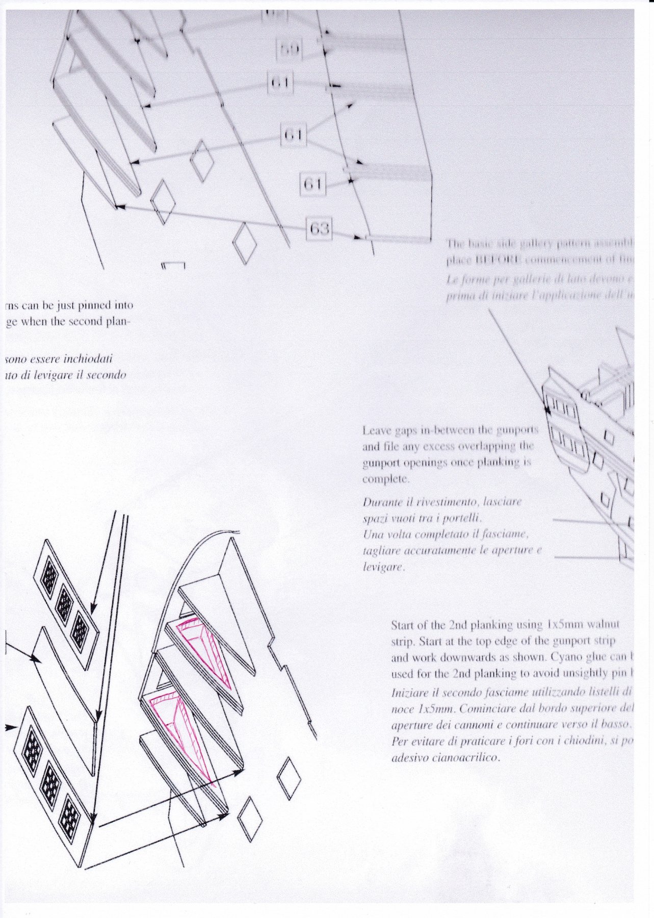
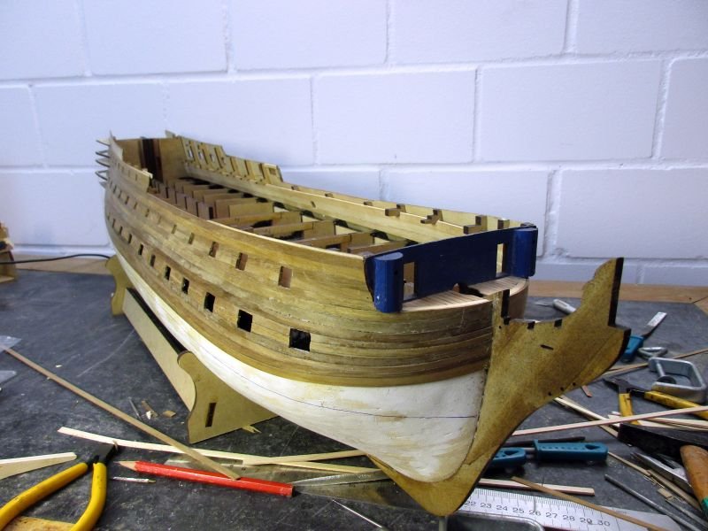
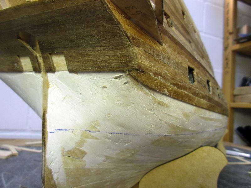
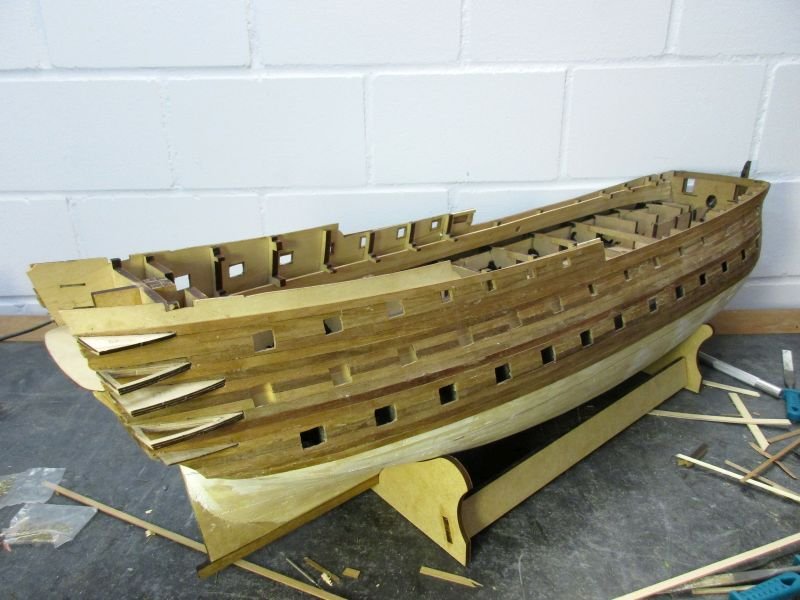
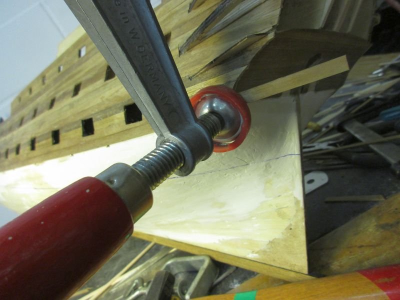
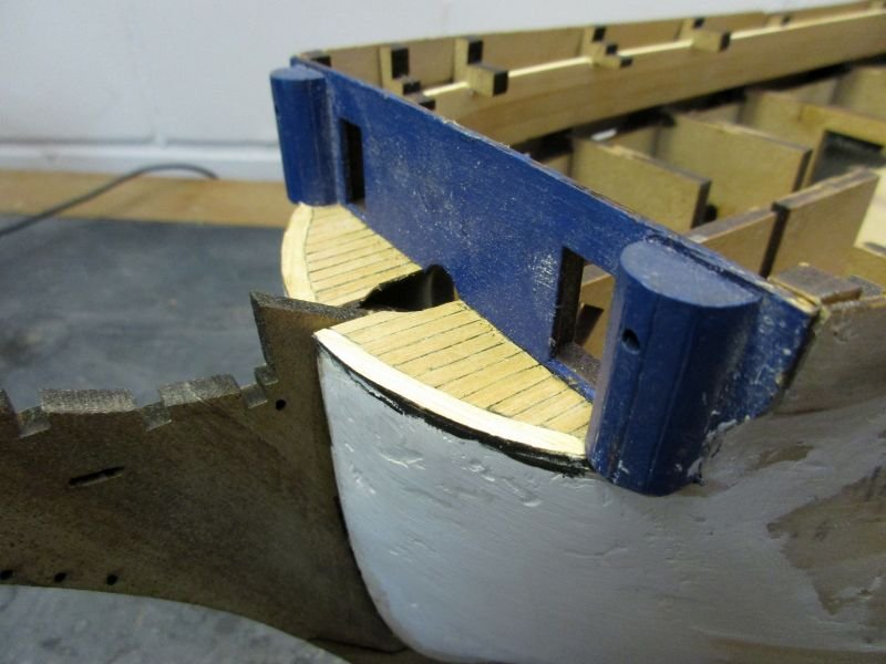
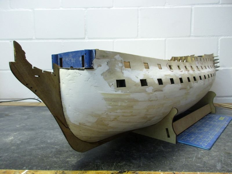
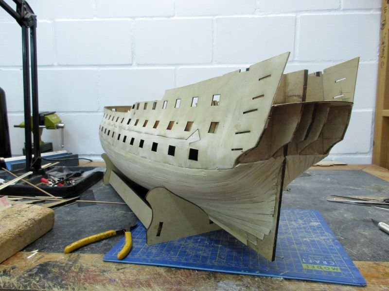
Second planking The first plank on each side, which determines the general run of the planks, was carefully put on with white glue. Thus I had enough time to correct. Then I tried to glue the next (soaked) planks with CA as I did on the last 2 projects. However it was messy work, did hold too early or not good enough and used a lot of rather expensive stuff. When cutting away the part over the gun ports the planks sometimes fell off again. Therefore I reverted to PVA and rather tedious fixing with clamps. However the clamps reach only down to the lower gun ports and below I had to fix the new planks with nails - mostly just below the lower side, in order not to leave holes, and a large vice. When one plank holds, I lay the next one in its natural run along and over the previous and mark the edge with a pencil. The superfluous part of the fixed plank is cut away with a sharp scalpel and the edge smoothed with a file. While gluing on plank by plank I started to cut open the gun ports. The blue line is a provisional waterline. Once below it I can freely use nails to fix the planks. The holes will be covered by the coppering. Still looking quite good...but the side galleries will be tricky work, I think. the lower corners of the lower counter are difficult terrain... The lower planks are fixed with nails below and the end with a big vice. So far, it worked 3 times.
- 366 replies
-
- 12
-
-
- bellerophon
- victory models
- (and 2 more)
-
Hi Bob After seeing your new gun carriages I had to compare them with those on my Granado. I'm sure that the difference will still be visible even in the mace of details on the finished model and the new things will be well worth the extra effort. Good idea! Cheers Peter
-
Hi Bob Me, I would very much like to follow a Granado log of yours. Seeing what you made of the Vanguard, your Granado should become something well worth her own diary. Not only might your followers learn some new tricks or new views, sometimes it's also nice to see somebody else struggling with the same problems I had and hopefully come to good and perhaps different solutions. And besides that it would be a nice place to chat a bit. Cheers Peter
-
Hi Bob Once again I must congratulate you on a superb and very clean build. I'm wondering where you would let evolution attach the third arm. For ship modelling purposes a good place would probably be on top of the head to be able to hold your piece of ship in a triangular grip... While stowing that anchor on my Pegasus I simply put a line around the base of one of the lower deadeyes. BTW why don't you like Granado's gun carriages? Cheers Peter
-
Hi Martin Bellerophon is a ship of the Arrogant class which was designed as a development of the Bellona class, sharing the same basic dimensions. All were based on the lines of Sir Thomas Slade's designs. As he was also the designer of the Victory I use her plans for confirmation of his general ways. The Bellona's plan - in the book you mentioned - is very similar to the plan of the arrogant class ship Edgar, published in 'The Billy Ruffian', but shows more details. The convex, smooth form of the taffrail, for example, is visible in both and differs from the kits rather flat one. I think that the kit is a great one but some simplifications, mistakes or misunderstandings may occur as well as financially motivated shortcuts. Therefore, if I am in doubt about the correctness of the kits instructions, I try to alter the model coinciding with my other sources. If in doubt I work towards what I think to be more pleasing to the eye because very often efficient war machines look quite elegant - a contradiction which is a little disturbing but nevertheless exists. So far this is the theory behind my building attempts. What I then manage to tinker together is the practise... Cheers peter
- 366 replies
-
- 4
-
-
- bellerophon
- victory models
- (and 2 more)
-
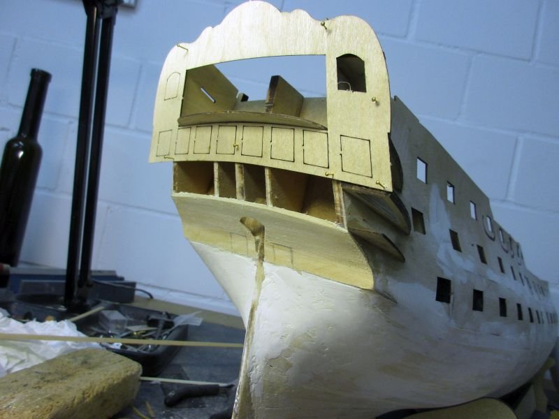
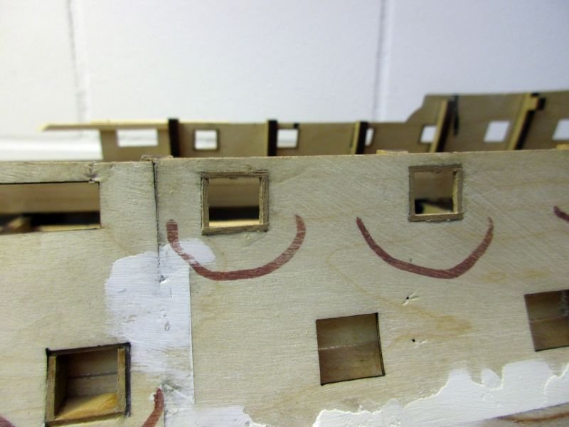
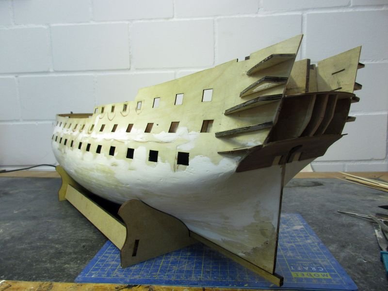
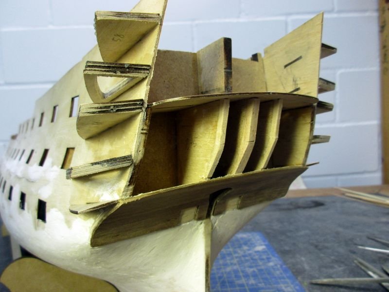
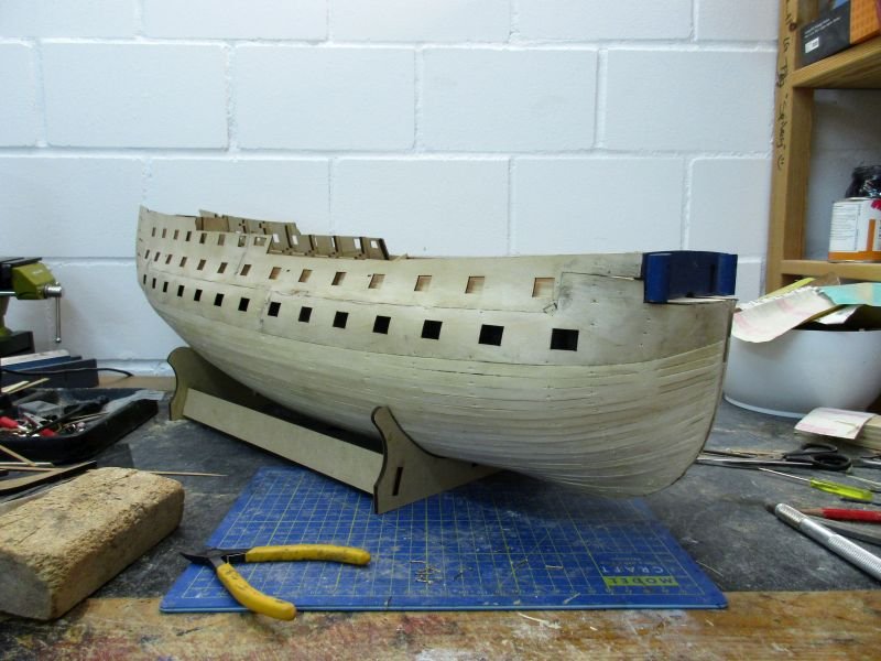
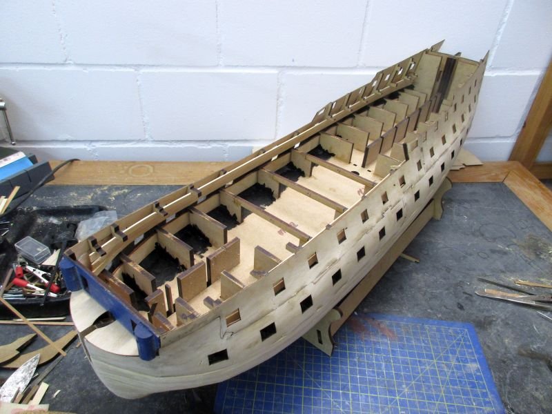
Preparations for the second planking The raw hull was now treated repeatedly with filler and sanding to create smooth lines. To check those lines I relied on the plans of Bellona with cross references to Victory using plans from the two books of the 'Anatomy of the ship' - series. The platform in front of the beak head bulkhead was planked. The plywood piece intended to cover the lower counter broke in two while I tried to fit it into the required concave form - despite the previous soaking in water. I then rebuilt the counter with some leftover planks and covered it with a second planking, leaving space for the two missing stern ports. Those were placed according to the Bellona plans. While building the skeleton for the side galleries I made some alterations. First I decided to plank the hull fully and thus set the side galleries onto the second planking contrary to the manual. This follows the method used on the prototype and will need some adjustments of the side gallery parts. Those two side gallery frames which are directly below the windows were hollowed out into open frames in order to (hopefully) give some additional depth to the side galleries (and some space for the officers using them). I also doubled up the rips which will later determine the form of the gallery windows of the officers wardroom. The kits lower gallery is almost flat and I try to get a more convex form as seen on the Bellona. Similar adjustments will be necessary for the poop deck to form the upper part of the transom. Some problems will arise with the decorations, for the Bellerophon as they are made as three white metal pieces, which I will have to bend somehow... All the gun ports without lids were framed because the second planking will run over the frames, finishing flush with the openings. Some of those frames were made up to three times because trials showed not enough headroom for the guns when placing the frames perpendicular to the planking. The frames were cut to give horizontal upper and lower sills. Finally the keel and the stem where glued in place, leaving the sternpost off. It will be added after sanding the second planking. first deck planking lower counter first planking with marked stern ports second planking on lower counter - altered side gallery frames also visible as well as the 3 lengthened rips which will determine the convex form of the transom rough gun port frames in place The wood strip was a bit too small even when setting it onto the inside planking. As the opening will later be painted I can use some filler to cover the gaps. her nice lines are starting to show
- 366 replies
-
- 13
-
-
- bellerophon
- victory models
- (and 2 more)
-
Hi Michael and Mobbsy Good to see you, welcome to the log.
- 366 replies
-
- 1
-
-
- bellerophon
- victory models
- (and 2 more)
-
Hi Bob But, that flag looks quite good. You could soak it with watered glue before folding to make the crinkles last. A few years ago I built Caldercrafts Granado which, I believe, is almost identical to the Amati kit. Perhaps CC provides the better manuals and certainly the better guns. The kit lets you build a great model with a lot of interesting details. There is also a book available in the Anatomy of the Ship series. Altogether Granado would be a very rewarding project and with the experience you have, you would be able to build a gem. Cheers Peter
-
Hi Bob As far as I can make out, the second pins from the front on both aftermost pin rails are free for the flag line. Or: Sometimes, when I run out of belaying points I use the same point to belay two different lines. I'm not sure about the real ships, but if you consider all those additional lines necessary for the sails (including buntlines, reef lines etc.) I guess they run sometimes out of belaying points too. If you don't like the flag coming with the kit, you could hand paint one on thin cotton and even choose the squadron you want to attach your Vanguard to. At the battle of the Nile Nelson was a rear admiral of the blue and she probably showed a blue ensign (as did the Titanic btw. either because Cpt Smith was a honorary CMD in the RNR or she was a Royal Naval Reserved Merchant Cruiser). Cheers Peter
-
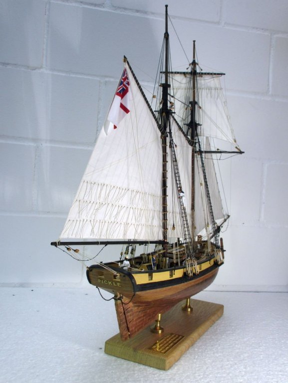
"... then have figure out what to do with the damn thing." Hi Bob In real live usually the admiralty decides where the ships have to go... Ensign halyard: Usually a single block (suggest 3mm) is mounted at the end on the main gaff. A flag line (0.1mm natural thread) passes through the block with both ends running. Both ends are belayed at the same cleat on the inner bulwark (or a similar belaying point) just about abeam of the block. That means that you belay the line on the cleat, the opposite end leads up through the block and back down to be belayed at the same cleat. The ensign is fixed to one of the ends. Similar cleats should be provided on both sides, port and starboard, to enable the ensign to be set on either side of the gaff sail. This description follows the manual of Caldercrafts 'Pickle'. I find CC's manuals usually very well researched and accurate. Below you find a picture of my Pickles Ensign and its halyard. Cheers Peter
-
Hi Bob Thank you very much. I will follow the manual then, and paint the inside of the gallery a light grey as on victory and the 'floor' dark grey to black. You just saved me a lot of unnecessary, fiddly work. Thanks Peter
-
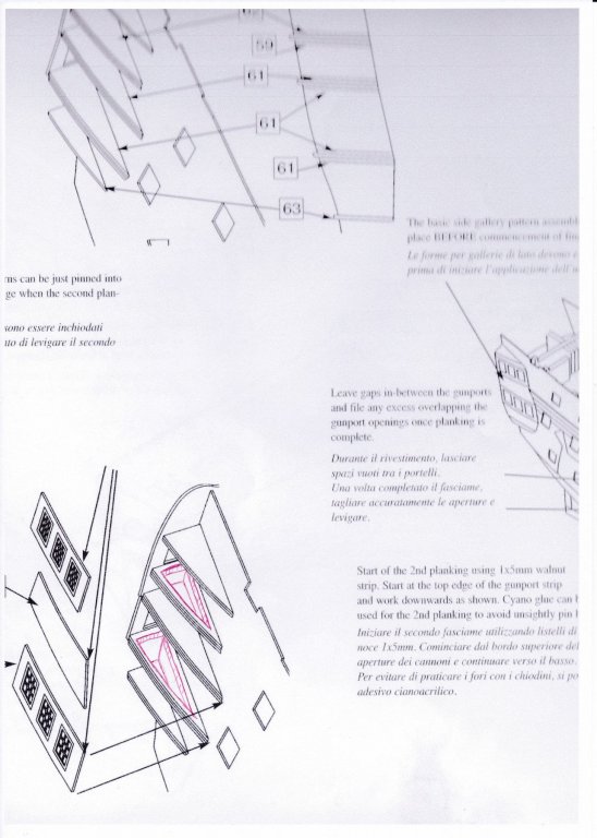
Hi Bob Thank you for the prompt answer. We are talking nearly about the same, only I was thinking of the inside of the side galleries. In the draft below You see the sections within the red marked areas on parts 58 (upper) resp. 60 (lower) which I would take out in order to create a side gallery which also has some depth below the windows. The question is now if you think you would see a difference -looked on from the outside of the finished stern- to your version where the 'floor' of the side gallery lies directly below the windows. Instead of nibbling those two closed triangles into frames with a high risk of braking them during or after the process, I think the surface could also just be painted black to suggest some depth. What do you think? Thanks Peter
-
Hi Bob You are making great progress on your wonderful build. To successfully correct a little mistake now and then is part of the fun - or so, I've been told... Watching your Vanguard coming to live is always a motivation boost for my Bellerophon build. A question, if I may: I'm actually pondering about those triangular side gallery patterns. I had the idea to work those two, on each side, directly below the windows into frames instead of the closed triangle. That way I hoped to create an impression of an real side gallery with some depth. The whole construction would however lose some stability and it would be fidgety work. Do you think the difference between your way of building, according the manual, and a side gallery with some depth below the windows would be noticeable at all from the outside? Happy modelling Peter
-
Hi Nils If you allow I'll be standing timidly in a back row to watch a master at work. I love the chebec - another very elegant ship! Cheers Peter
- 692 replies
-
- 5
-
-
- eagle of algier
- chebec
- (and 2 more)
-
Hallo Nils You are a true artist. Congratulations to finishing a great project. Peter
- 2,625 replies
-
- 5
-
-
- kaiser wilhelm der grosse
- passenger steamer
- (and 1 more)
-
Hi Martin After soaking them in water for 1hour it went quite well. The correct placing of the gun ports in regard of decks and frames is a bit tricky and if I really was successful will show only when trying to place the gun port frames and the guns. However the necessary bending in two directions of the stripes produced some of those mentioned bumps and dents (visible in the third picture where the plywood joins the planked part). Thank you, Mike Hi Jason Yes, 1/64 would be great but huuge! And 1/72 is almost the same - just imagine the original ship being only a bit farther away from you. Thanks for the information about the rail. So the Trafalgar configuration was probably as per kit. However as there is no definite information I will take the liberty to build as the plan in the book or those from Bellona show and pretend that the bulkheads were never heightened. Cheers Peter
- 366 replies
-
- 3
-
-
- bellerophon
- victory models
- (and 2 more)
-
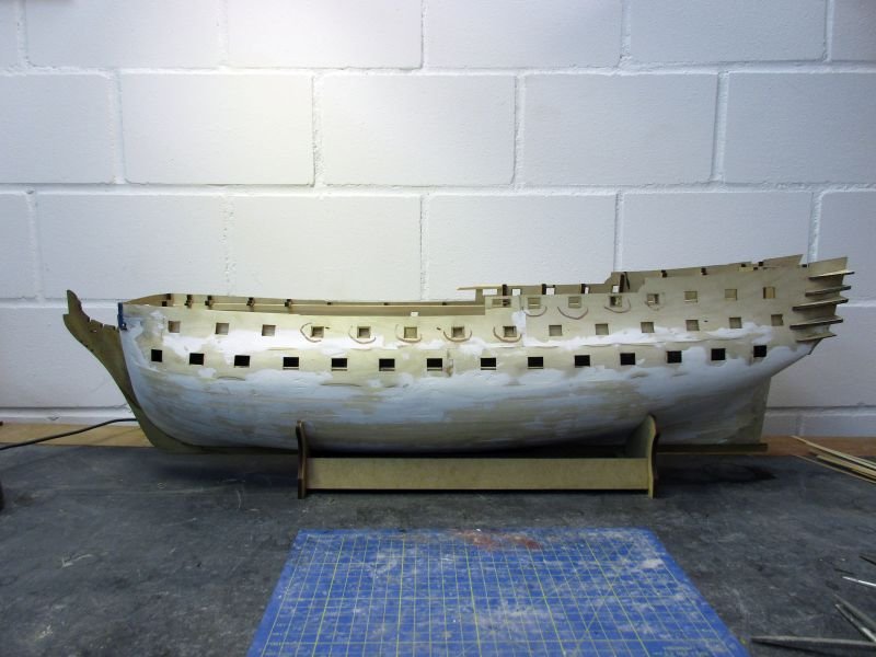
Despite some distractions the first planking is now finished. Some dents and humps are showing and sanding, filling and sanding again will now start in earnest to get that hull shape which was intended by Sir Thomas Slade.
- 366 replies
-
- 14
-
-
- bellerophon
- victory models
- (and 2 more)
-
Hi Mark and Mort Didn't' spend enough time in the yard lately - I had to read that book. While there is just some additional information in regard of building the model, the story is catching, interesting and a great motivation for the build and very well written - a page turner. Thanks again for the hint. Cheers Peter
- 366 replies
-
- 2
-
-
- bellerophon
- victory models
- (and 2 more)
-
Hi Martin. Especially the shot depicting a birds view shows how wonderfully those steps fit your Pegasus. Great work. Cheers Peter