


flyer
-
Posts
1,016 -
Joined
-
Last visited
Content Type
Profiles
Forums
Gallery
Events
Everything posted by flyer
-

To add sails or not? What is your preference?
flyer replied to Bill97's topic in Masting, rigging and sails
I do agree with RussR. A sailing ship must have sails. My 3rd model was the first with (furled) sails. As I didn't know better I used pre-sawn sails and learned a lot. The main points are already mentioned in other posts here: Never use them and when sails are furled reduce the height by 1/3. The next try -Granado- was with furled sails made on order by a professional seamstress. I just sawed the boltropes on. As pointed out here the seams are much to coarse and also the boltropes still seemed too prominent. Then I made the sails myself, just pencilled the seams onto the fabric and glued the boltropes into the seams. Furled they looked good enough for me to try full sails on the next two models - both schooners. Now I'm coming to the point: There is a further possibility - you have partly set sails. For example leave the topgallant sails furled, set topsails as in medium wind and perhaps have the mainsail furled as well. Just choose a scenario, such as e.g. ready for battle in moderate wind, and set the sails accordingly. A benefit of full or partly set sails is the fact that you can brace the yards as sharp as you like and the rigging allows which gives a more dynamic look and reduces the space needed for the finished model (by about 15% for yards braced 30°). I'm building a 74 now and will add sails, do however not know yet how exactly. They will most probably be partly set because I want to brace the yards.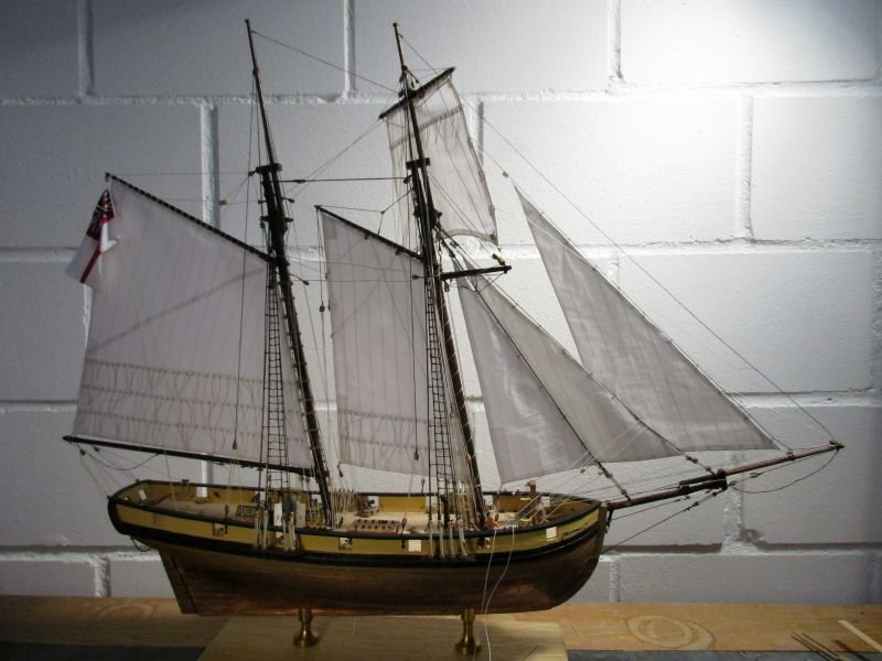
-
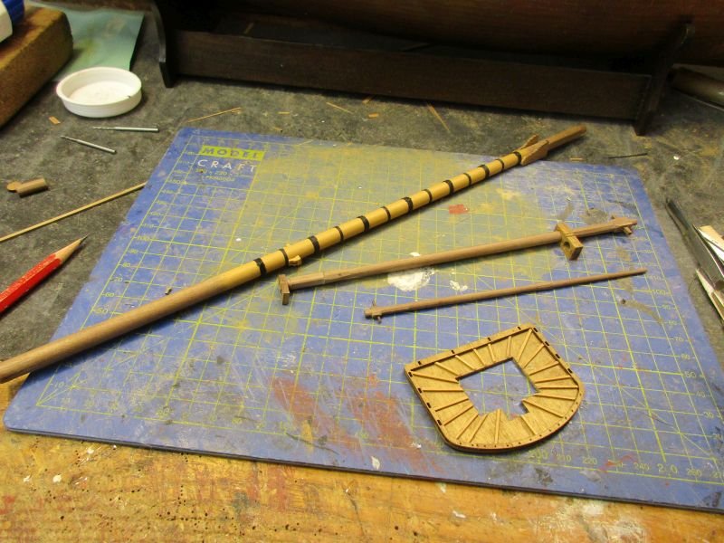
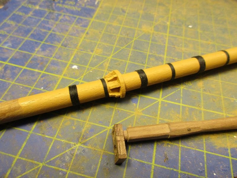
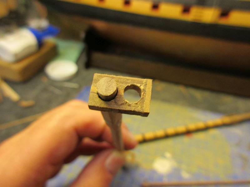
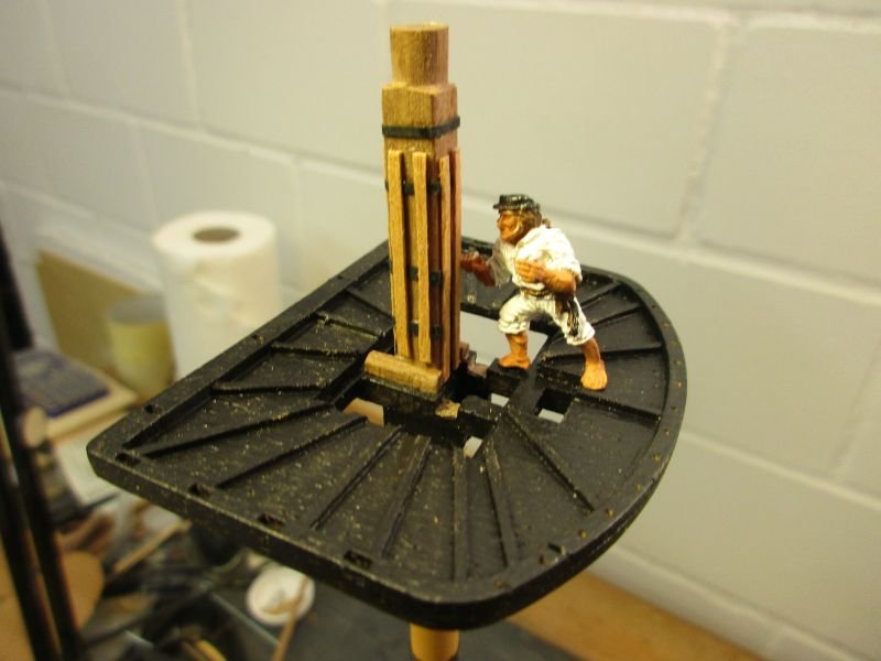
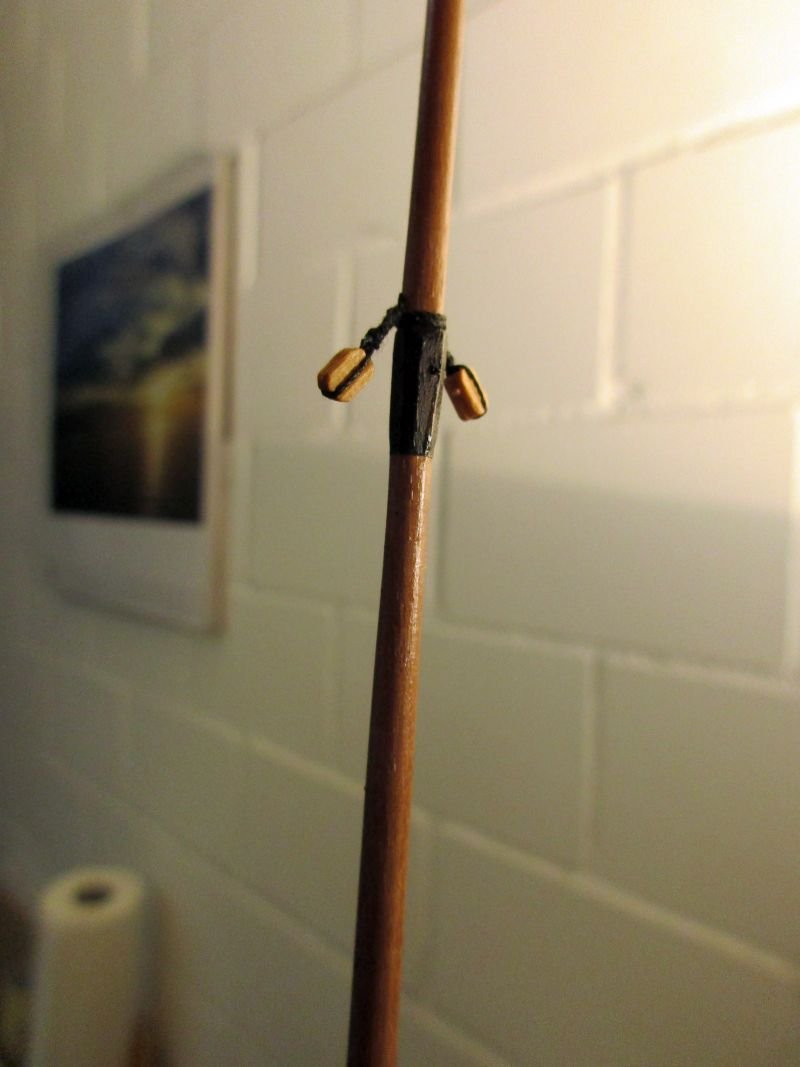
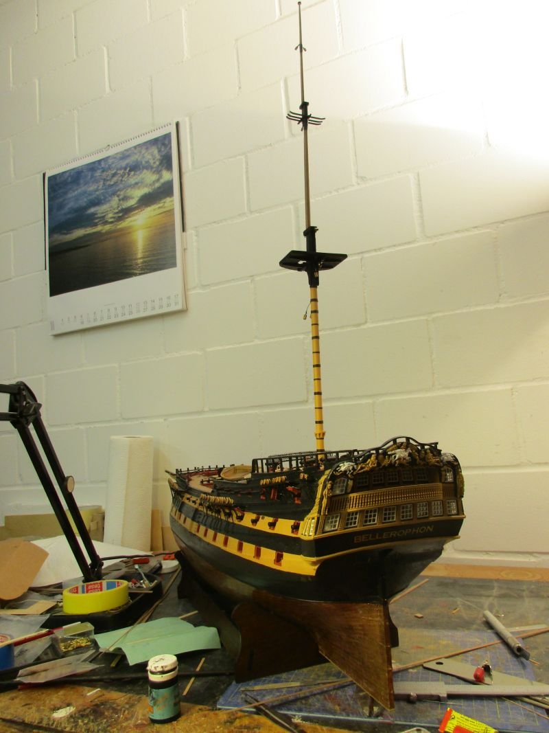
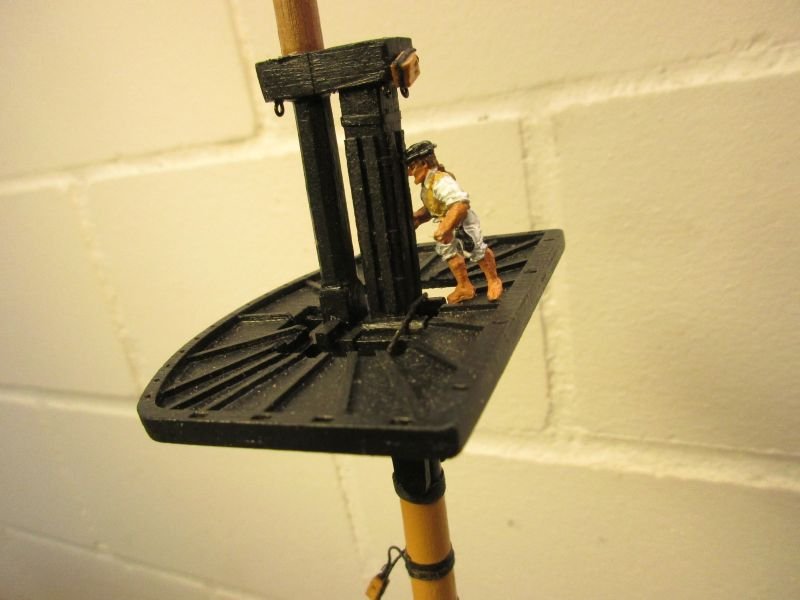
Mizzen mast In order to make the following work more varied I decided to alternate between building a boat and a mast. As the mizzen mast is the smallest I started with that. Still having no lathe I had to file the dowels first square, then octagonal. Then they were put in a drilling machine and worked round with increasingly fine sanding paper. So far I made all my lasts and yards that way and it seems to work. The mizzen presented some minor difficulties. The lower mast was quite straightforward to build, only a saddle for the boom was added. Several books, e.g. 'Victory' in the AOTS series show such a device but not my main reference of the Bellona. But she still shows the lateen mizzen yard. The foots of the topmast and topgallant mast were doubled up to a rectangular form, not square. This was necessary to fit them in the right distance to the lower mast heads into the tops. The topmast cap was also too small to fit and had to be doubled up by 1mm in length and width and the holes were slightly adjusted to get the right distance. I don't quite understand why the caps are presented lengthwise cut in two and quite imprecisely so. A cap in the right size in one piece as in other kits would be easier to work with and more precise. The fact that the head of each mast and its hole in the cap should be square and not round was not corrected - black paint will hide that flaw. The mizzen top got also some vertical battens glued on, on top of the iron rings which strengthen the mast head. A rather minor but important change was made to the top of the topgallant mast. The plan shows a 1mm hole front to aft just below the top for the tie of the topgallant yard. It is rather unwise to weaken the mast in its thinnest position that way. I remember at least one model where I broke a topgallant mast in exactly this position twice when I got caught during rigging work. According to Lees the tie was led anyhow through sheaves in the masthead so I drilled that hole about 1 third from the top through the head. As always I finished the mast off the ship and glued all parts together. That way I have a mast with all parts truly in line. The shrouds may be attached without problems to the finished mast. lower mast, topmast, topgallant mast and top - fids already inserted saddle on lower mast and reworked topmast cap topmast cap being reworked - the left hole and the head of the lower mast should actually be square mizzen top. iron rings, bolsters and battens added topgallant top with hole for the tie finished mast top with blocks attached the first mast stands provisionally - this model really takes up a lot of space
- 366 replies
-
- 11
-

-
- bellerophon
- victory models
- (and 2 more)
-
Hi Martin A search in the web revealed that that belt was a gift and it was dyed purple. I guess that was an expensive colour then. However nothing about its construction - some fabric perhaps. Anyhow, I'll think about adding a purple belt to my Bellerophon. So, you are close to moving. Might I ask where to? Someplace which is cooler, with more wine and less tornadoes and cows perhaps? Cheers Peter
- 366 replies
-
- 1
-
-
- bellerophon
- victory models
- (and 2 more)
-
Hi Bob It definitely looks much better. Don't worry, be happy. Perhaps even when building - or repairing - the prototype they didn't always have the right strength of rope available either. And of course they would take the next stronger one. Anyway, I keep telling myself, that all the snags and imperfections on my models make them to look more realistic, because working conditions back in the 18th and 19th century weren't perfect either. Cheers Peter
- 421 replies
-
- 1
-
-
- caldercraft
- granado
- (and 1 more)
-
Hi Snowy Yes, the same stripes for 1st and 2nd planking and yes again I tried to stagger it by starting the 2nd planking a bit too high and then sanding off the top 1mm of the 2nd planking. (With some foresight I would however have done this to the 1st planking because it would be less obvious.) Anyhow I still had a few areas where the seams of both layers met - and split during sanding. Reinforcement with liquid CA glue helped. Btw I used CA glue for the whole 2nd planking and epoxy glue to fix the rails. Hi Sailor1234567890 Well I think you could start with the boats. Me, I was impatient to see the real dimensions of the ship and started with the big one. I don't know if you could use the boats as training pieces, if that is on your mind, because they are fiddly work and you have less room for corrections with those thin planks. I had to check where that place Shubenacadie is. I hope you forgive me that I had never heard of it. Well, that looks like a nice location, quite close to Halifax and therefore much closer to the sea and the navy than my place. Cheers all Peter
- 366 replies
-
- 2
-
-
- bellerophon
- victory models
- (and 2 more)
-
Hi Martin A bit belated I rise an answering glass towards the west - one of my last Corona beers. It's too hot for red wine. About Bellerophon's belt: Was it perhaps mentioned in some writing or seen on a statue? I only remember Orion's belt and would know how this one looks... Take care Peter
-
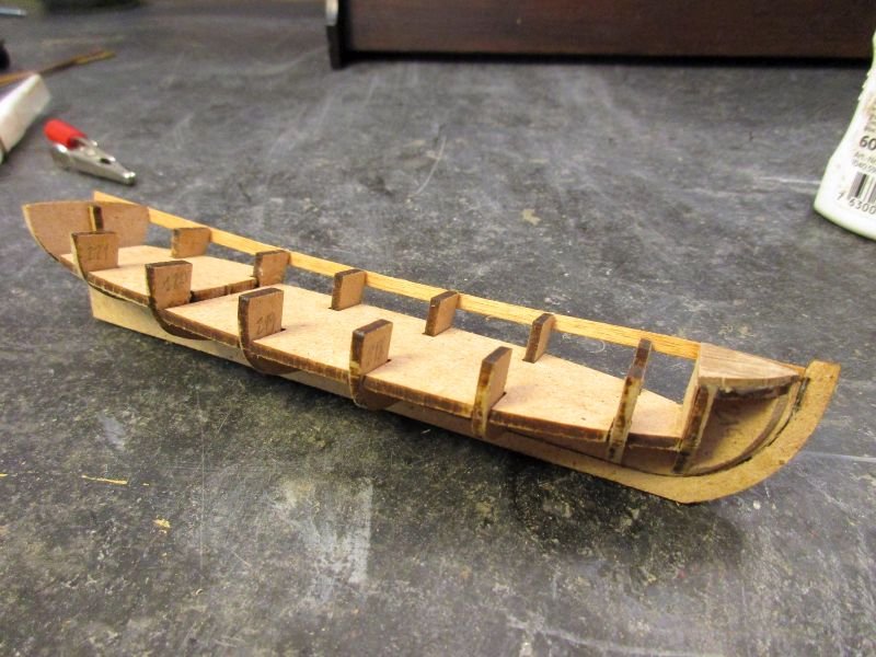
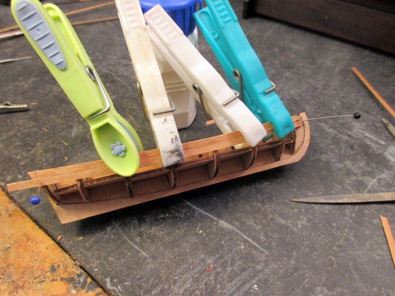
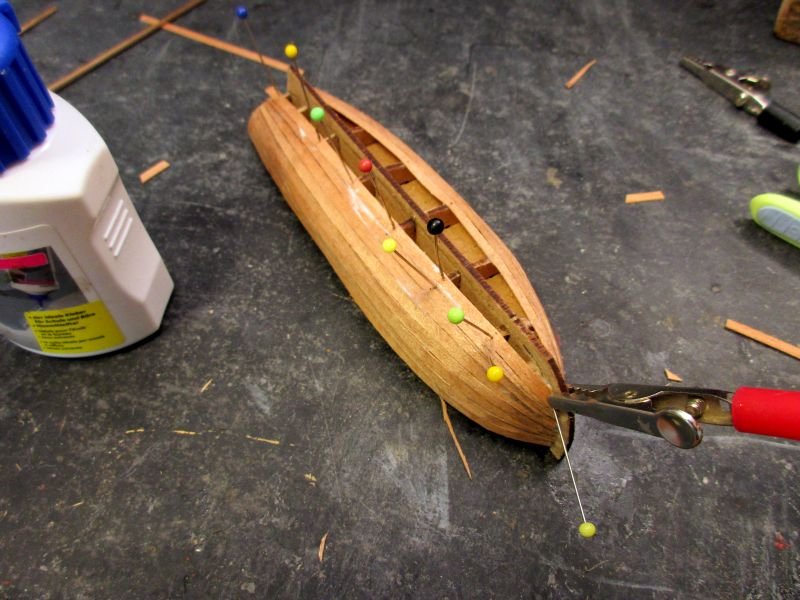
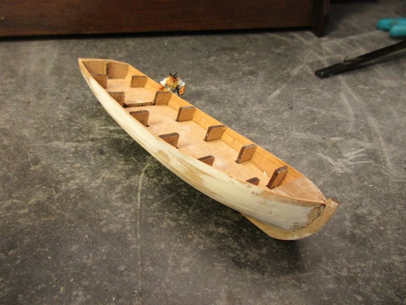
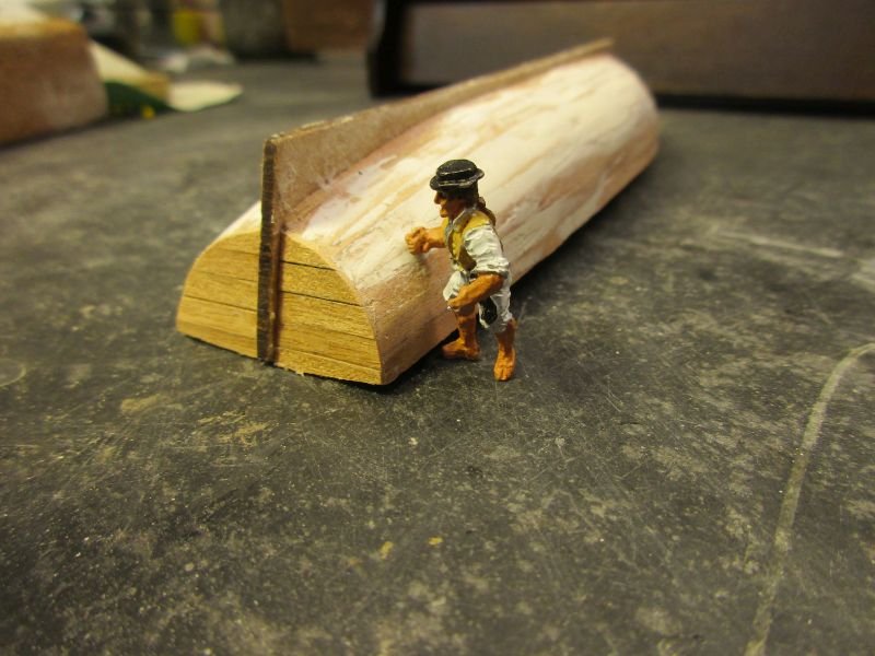
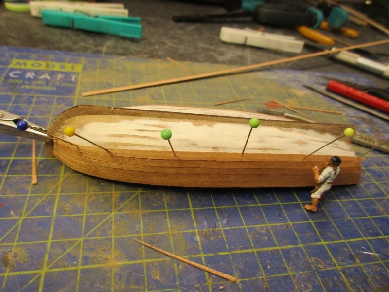
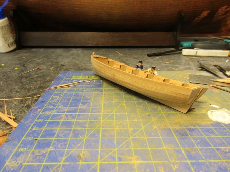
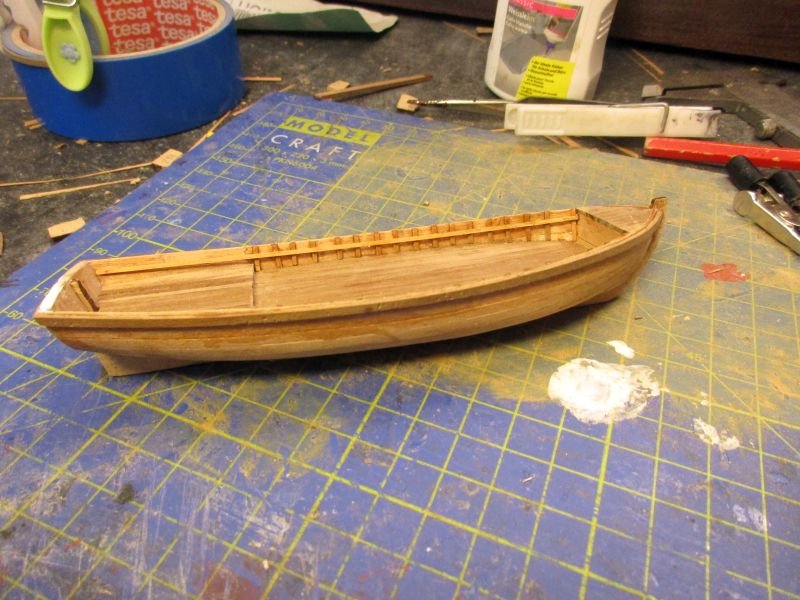
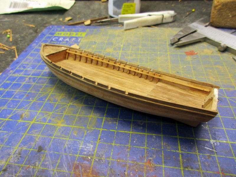
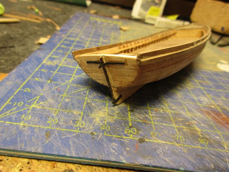
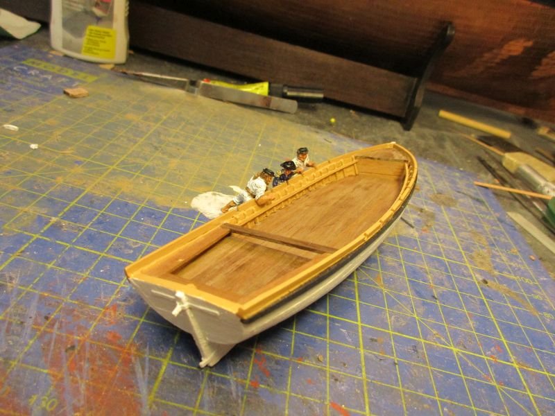
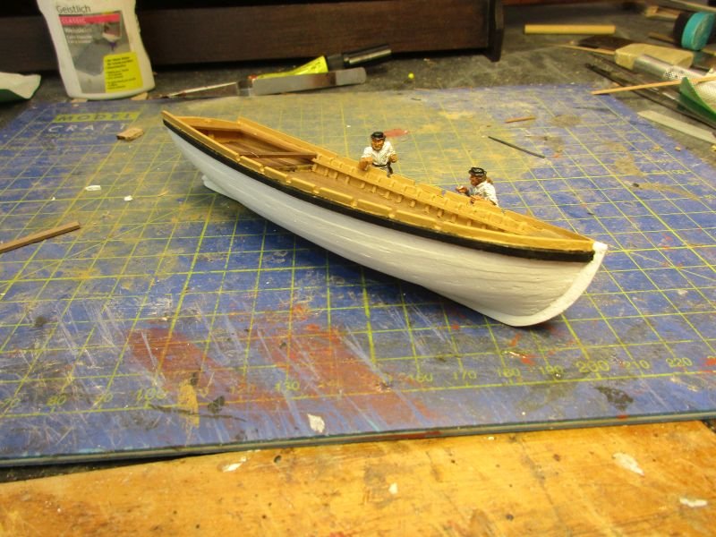
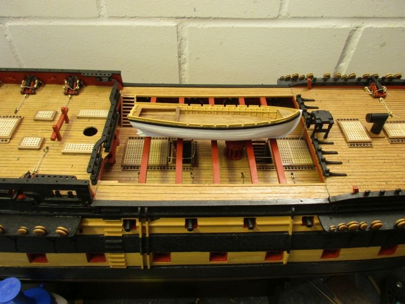
34 foot launch Next I wanted to try the first boat. According to the manual I started with the big launch. Up to now I used resin shells with additional built in details to make boats. This was the first plank on frame built. It went quite well albeit much slower than the 3 weeks the manual mentions for all 4 boats. Also not everything went as intended. When putting in the ribs, the base of the floor boards in the aft part proved to be mounted askew. I hope to disguise this mistake with the benches and perhaps some of the boats equipment stowed inside. The inside was painted yellow with floorboards and benches only varnished. Most of the outside is painted white with black wales and a yellow rail. After about two weeks of occasional work the launch is finished. No thwarts are put into the launch because the 18 foot cutter will later be placed inside. She is quite large compared to other boats I made so far. But I can see the usefulness of such a craft for a variety of tasks. I don't remember seeing much about building these boats in other logs. Therefore I put some additional pictures into this one. Skeleton with first plank. First planking in progress... ...and finished. Some filler was necessary to get smooth lines. The transom was planked horizontally - contrary to the manuals vertical planks. 2nd planking under way ... and finished. Now the bulkheads were removed. floor boards in place The rail was preformed and added in one piece and then the rowlocks filed into it. 2 stripes of cartridge paper serve as gudgeons for the rudder. The finished and painted launch is checked by the crew. Provisionally put in place on the beams of a 74 the launch looks huge.
- 366 replies
-
- 11
-
-
- bellerophon
- victory models
- (and 2 more)
-
Hi Bob Now I see that the 3mm blocks in fact also look a bit thin - especially compared to your wonderfully detailed bowsprit shrouds. I'm afraid that from now on you will always look at that tackle in a sceptical light and if you ever want to be happy again you'll have to install something like a tackle with 5mm blocks and 0.25mm thread. Sorry for that trouble. Cheers Peter
- 421 replies
-
- 1
-
-
- caldercraft
- granado
- (and 1 more)
-
Hi Bob Your rope works look excellent - the Syren thread is a tremendous improvement. However as an engineer something chafes me: That stay on the starboard side of the bowsprit (main top stay?) has to take a certain load. The whole load has to be transmitted via the tackle to the belaying points. Each of the 3 legs of the tackle takes 1/3 of the load which means the thread of the tackle should in this case be at least 1/3 of the strength of the stay. Yours seems to be quite thinner and will either break when the stay takes the full load or the stay is oversized. It just doesn't look balanced. May I suggest to use the next stronger thread as tackle? Take care Peter
- 421 replies
-
- 1
-
-
- caldercraft
- granado
- (and 1 more)
-
HMS Victory by Helli - Caldercraft
flyer replied to Helli's topic in - Kit build logs for subjects built from 1751 - 1800
Hi Helli Thank you for sharing that amazing build with us. That's a very clever trick for attaching the breaching rope rings to the guns. And your work looks great, clean and precise. Cheers Peter -
Hi B.E. Another great build where you improved an already excellent kit by adding your personal touch. Congratulations on a masterpiece. The unavoidable question: And now? Cheers Peter
- 335 replies
-
- 1
-
-
- alert
- vanguard models
- (and 1 more)
-
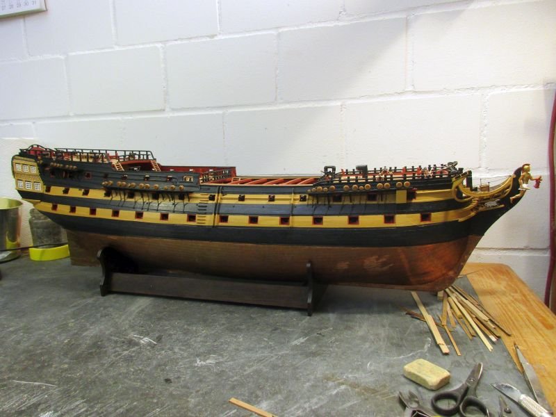
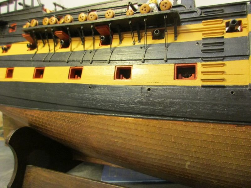
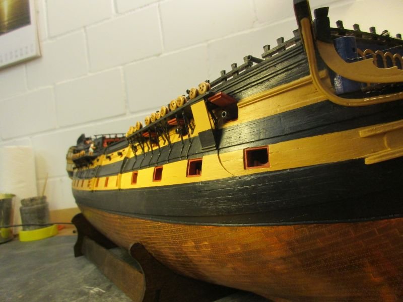
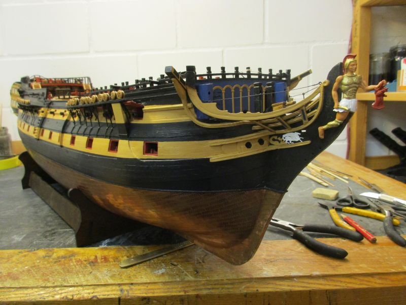
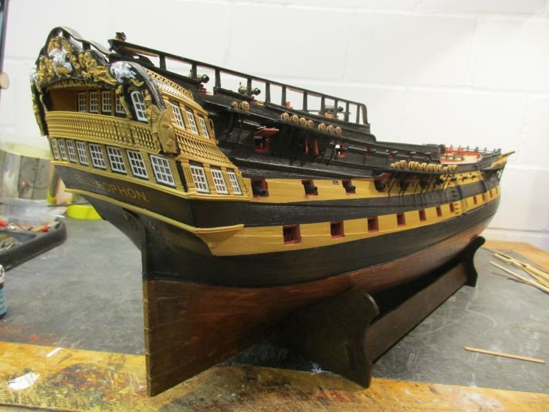
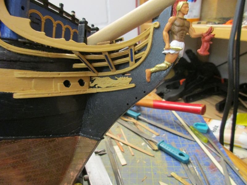
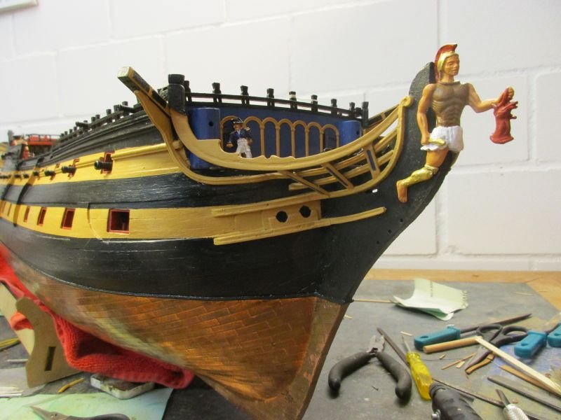
All the channels are in place as well as those gun port lids which are between the chains. To improve the stability of the chains I tried to close the middle link with some tin-solder. It doesn't look perfect but seems more stable. While constantly turning the hull for and back I came across our hero's sculpture every time and was more and more irritated by his brown breast armour. As higher Greek ratings anyway were entitled to a metal protection I replaced his leather by metal and even offered a heroic gold plating - means I painted his breast golden. It looks now more in line with the other colours, simpler and better. mizzen channel fore channel our hero looks good in his new, shining armour scuppers Perhaps it's just another one of my obsessions but I try to install scuppers on all my models. They should show that ship's hulls are just fragile and leaking eggshells and the water which comes in has to go out again. Learning where to install scuppers was difficult. Finally I found a note in 'Bellona' from the AOTS series saying that there are 6 per side on the gun deck and 7 per side on the upper deck. However no plans where to install them were included. I think that those on the gun deck could be installed similar to those on frigates where I found some information and for the upper deck I will try to find logical positions. It seems that scuppers: - are about evenly spaced in the central part of the deck - are not below a gun port and therefore covered by a gun - may be in the form of a slightly bigger pump dale near the mainmast Scuppers on the upper deck should additionally not be above a gun port or a scupper of the gun deck. The locations were chosen accordingly and the one near the mainmast on the gun deck is a pump dale and therefore slightly bigger. I used again ferrules from the electric compartment with a diameter of 1,5mm respective 2mm for the pump dales . As they are all placed within the black wales I painted them black as well. all scuppers except the foremost on each deck main channel with scuppers the second scupper from the left on the (lower) gun deck is a slightly larger pump dale stand Originally I planed to step Bellerophon onto 3 pilars mounted on an oak base, similar to Pegasus, Pickle and America. I like those stands because the model almost seems to float on them. But while handling that rather heavy hull and thinking of the rather sof MDF which should hold the 3 screws which in turn would take all the strain I started to have doubts. Some destruction tests with leftover MDF slid into the pilars' slot did nothing to dispel those doubts. Reluctanly I accepted the kit's craddle as final support for the model. Painted with palisander stain it achieved a colour slightly darker than the aged copper but lighter and more elegant than the dull black shown on the kit's box. Most of the still missing, fragile details on the hull will have to wait until the rigging is completed. I think the fuselage could be delared completed and it's time to start on the wings. Also this is the time for a celebration beer - I'll check if there's still some Corona brew in the cellar. ready to launch...
- 366 replies
-
- 21
-
-
- bellerophon
- victory models
- (and 2 more)
-
Hi Mark Great work again. Good start on the copper plates although they aren't yet fully on the quality standard of the rest of the build. Just an idea: Didn't somebody in MSW use a stamp to make all rivets on one plate together? This would mean you would have to fabricate a stamp made of a piece of plastic (wood would be too splintery) with about 30 to 50 tiny nails or perhaps better pin-tips in it, protruding all the same length. This would be tricky work but if it is possible I think the making of the 2000 or so plates would go faster and you would have a regular pattern. For info: My Amati plates are 17 by 5 mm and have 2 rows of 9 rivets after 1 and 2 thirds of the width and a row of 18 rivets at the edge. This makes a distance of about 1,7 mm between the rivets, but only 0,9 mm distance along the edge. Good luck! Peter
-
Some 40 years ago I started with Corel and Mamoli kits. Among the shortcomings of those kits were the manuals. However, if I remember correctly, they also had the original Italian text included. Sometimes I was able to find some sense there, using sketchy French, translating some key words and by eliminating the impossible. Your model BTW seems to be pure Corel fantasy. The original Valiant of 1759 was a 74 gun ship of the line - quite different. Therefore you can't do wrong and are free to build it as you please. You're the skipper, look for the most simple and logical solution. I also wondered what kind of sloop could have been the pattern for this Valiant. Perhaps the sloop Speedwell 1752 was a close cousin. You'll find some pictures of her in the web (there is a model in the NMM) which could help to answer questions and ultimately perhaps even to modify your kit a bit to resemble a real ship. Your build looks fine so far. Go on! Peter
-
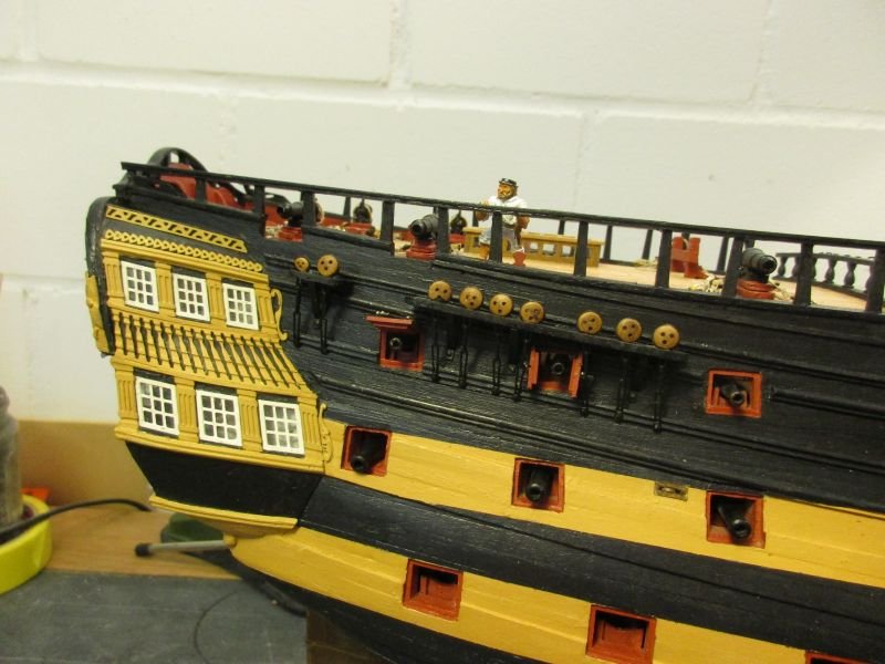
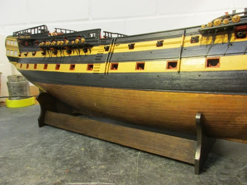
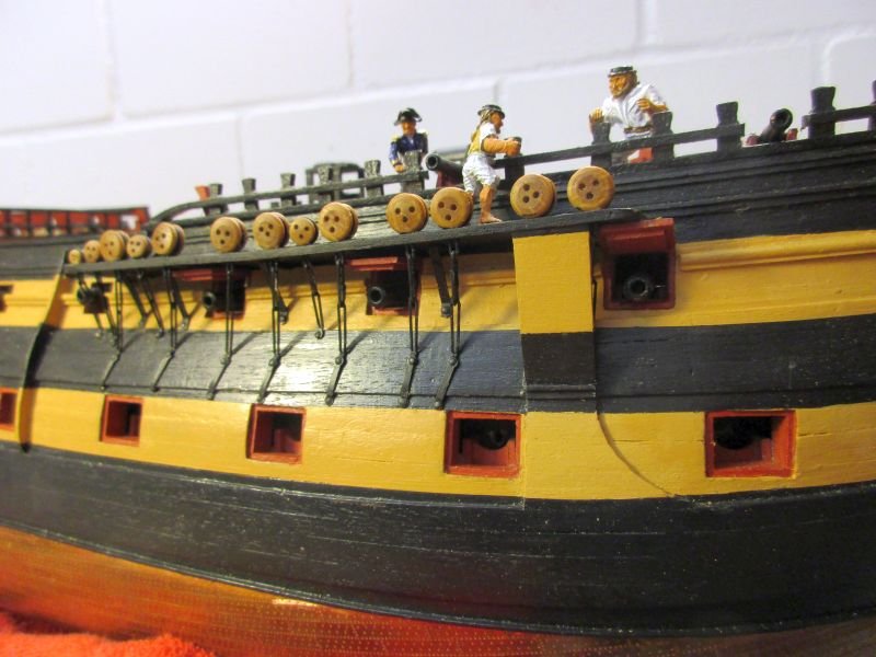
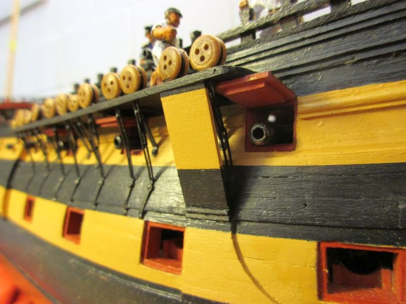
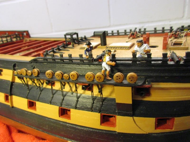
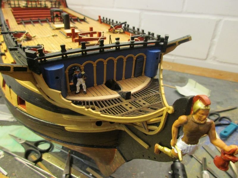
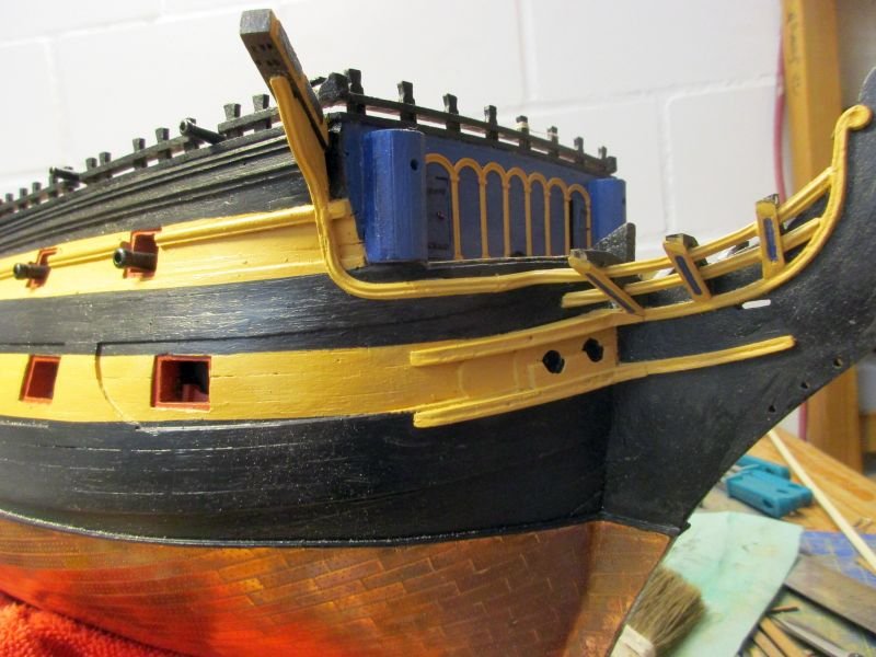
Finishing the hull Next was the starboard fore channel. Instead of wooden knees on top, the kit contains iron supports below to stabilize it. I'm not sure if this is historically correct but the Victory in the AOTS series book shows similar features. And they are in the same positions as the knees would be. So I followed the easy way and did as the manual told me. Fortunately I found RMC's note about attaching the associated gun port lids together with the channel and could avoid later difficulties. A feature I wanted to add was the anchor lining or bolster. In the AOTS books Bellona and Pandora I found drawings to show some information about the form but there was still some guesswork needed to build them as historically correct as possible. Finally I tried to keep it simple while offering maximal protection for the chains without blocking the foremost gun too much. It looks OK. The skipper came to enquire about the argument between the carpenter and his mate. anchor lining
- 366 replies
-
- 9
-
-
- bellerophon
- victory models
- (and 2 more)
-
Thanks Michael Had a discussion with a bank clerk about passwords. Even she uses the same for all her accounts and credit cards - it isn't "1234". So I feel justified to use the same few passwords for the accounts without safety risk. Don't ask me however, which one I use for MSW. Never been on one of those plastic aircraft. But it seems an interesting concept, also when you consider all those fume events (extremely harmful oil residues from the engine lubrication system entering the cabin via traditional aircraft air conditioning systems) which happen again and again on other aircraft. But I don't thrust those composite hulls regarding ageing and especially small ground collisions (e.g. ramp vehicles overnight) because you probably won't see a trace of them in the morning although the damage will be there, within the layers of the material. But as long as they are new and the batteries don't have a thermal runaway - they are certainly great birds. Cheers Peter
- 366 replies
-
- 3
-
-
- bellerophon
- victory models
- (and 2 more)
-
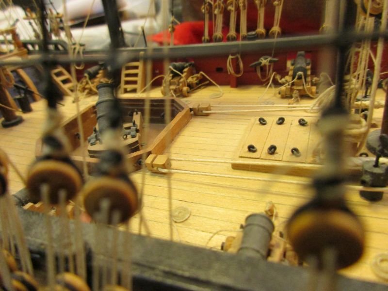
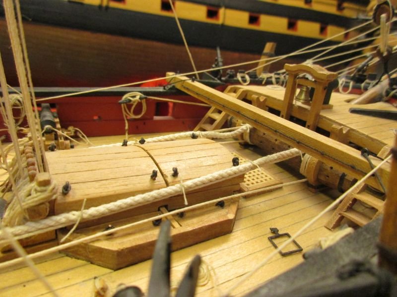
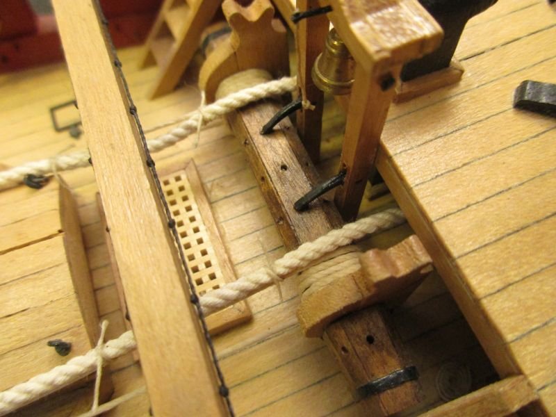
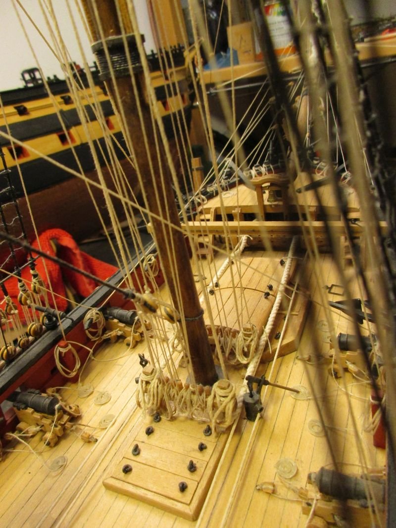
First of all, I think the two messengers should be spliced end on and thus forming endless slings with a few turns around the windlass (to create enough friction), leading aft trough those blocks at the aft mortar bed and back onto itself. In operation the windlass moved the messengers continuously round and round while the anchor cable(s) were temporary bound to the messengers to be pulled by them. The aftmost attachment was always taken off, brought forward to fix the newly inboard brought part of the cable to the messenger again. The cable aft of the messenger was lead below to be stowed there. Taking photos of the finished model wasn't easy but I hope you find some useful information there. Cheers Peter
- 421 replies
-
- 6
-
-
- caldercraft
- granado
- (and 1 more)
-
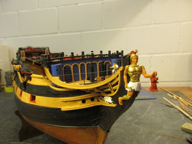
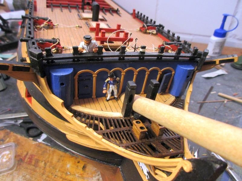
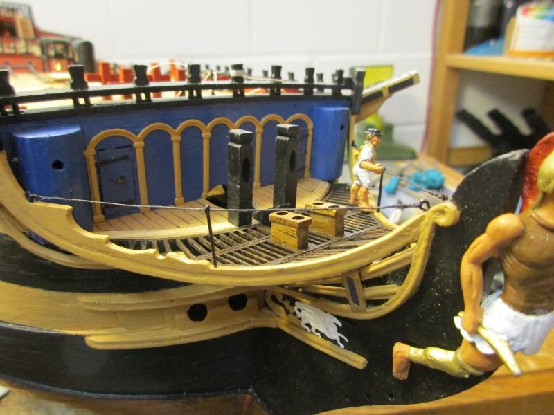
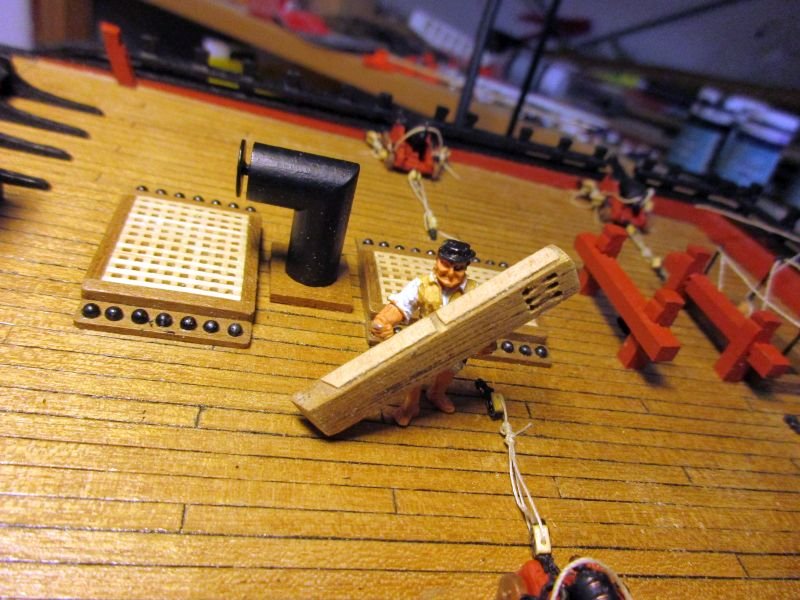
The next problem was how to place the ornamental Pegasus between the bow cheeks - it was more than 1mm too high. After cutting away the laurels and bending the horses legs a bit it fit but looked very meagre. As an alternative I reworked the Vanguards respective element to fit, thinking with its serpent head it could represent the chimeras carcass with its snake tail. Then I took the snake Elephant's elephant was trampling and combined it, with the same idea in mind, with the slimmed Pegasus - this looked to be the best version. The carpenter in the meantime had repaired the grating, installed the latrines or seats of ease and fixed the two knight heads on both sides of the provisional bowsprit. Finally the skipper - always with the welfare of his crew in mind - wanted a rope rail installed above the head rail to prevent them falling overboard while being at ease. a reworked element from Vanguard the final version with a part of Elephant and Bellerophons Pegasus the skipper examines the finished bow and criticizes the inadequate protection rope rails added with some leftover stanchions
- 366 replies
-
- 11
-
-
- bellerophon
- victory models
- (and 2 more)
-
Just checked my old plans sheet4: The mizzen yard is the crossjack yard, has a length of 190mm and is made from 4mm dowel. The centre part is 46mm in length and is 4mm round (should probably be octagonal). The two, 72mm long, outer parts taper from 4mm to 2mm. Cheers Peter
-
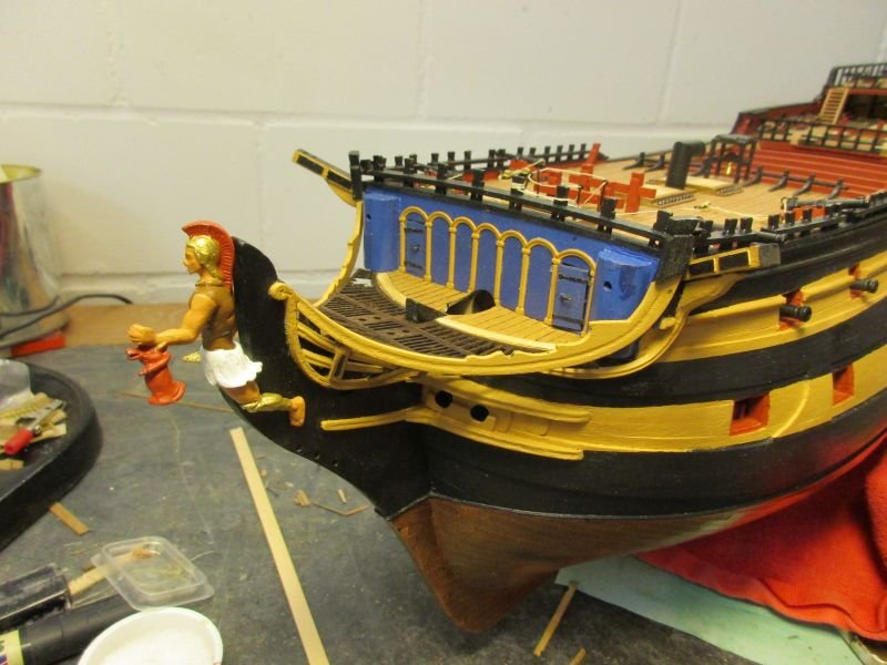
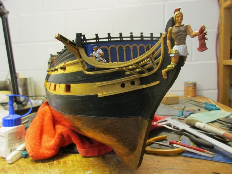
While working on the port side I tried to give the upper rail a more elegant run up to the cathead. Unfortunately I succeeded and knew I had to redo the starboard upper rail. Before I put the port head rail in place I glued the head gratings in. I used walnut stain on them and added a 1x1 mm strip across the foremost part to cover the foremost bow rail frame entirely. Then the starboard rail came off again and - because Mr Murphy had time to pay a short visit - 3 bars of the grating with it. The new rail however looks much better now. The figurehead got another layer of paint and a short search in the web revealed that Greek soldiers had metal greaves as a shin protection. They were available in metal for the elite and anatomically formed and reached around to cover also the calves. In case of our hero they are not only metal but I offered also gilding which means I painted the entire lower legs golden. the port side upper rail looks more elegant with the head rail added, the bow is almost complete the gratings in place the new starboard rail looks definitely better the skipper ponders about how to repair that grating

- 366 replies
-
- 11
-
-
- bellerophon
- victory models
- (and 2 more)
-
Hi Snowy A very clever idea and an equally successful sword transplantation - and the patient even is alive! He probably used a sword to cut off the head, while he used a spear (with a lump of lead on the tip) to kill the beast. I'll think about a spear in his hand while trying to find out what he actually holds. Stay cool! Peter
- 366 replies
-
- 1
-
-
- bellerophon
- victory models
- (and 2 more)
-
Hi Martin Despite any shortcomings you may see, the new figure head is a great improvement. If you really are looking for a cooler region to live, could I perhaps propose this?: Hope this is cool enough. Ok, the lake isn't even fully frozen but it's still a few weeks to go until you reach the lowest temperatures. Every February there are horse races on the lake - no Pegasuses or seahorses allowed, so the lake must be frozen. (Over the holydays I was going to hike a bit in the snowy mountains but got a severe cold the first day and was reduced to stroll among the tourists at St Moritz.) A very happy new year to you (and everybody here)! Peter

- 467 replies
-
- 1
-
-
- fly
- victory models
- (and 1 more)
-
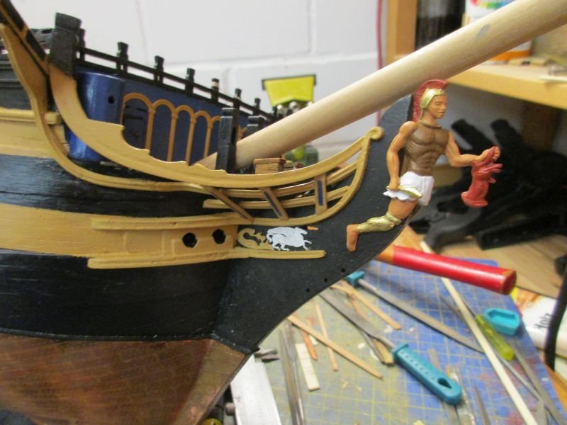
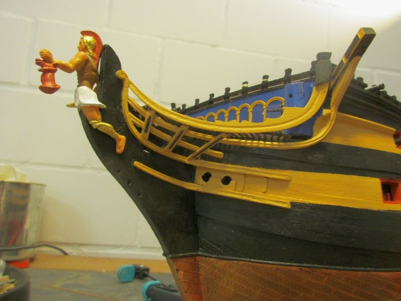
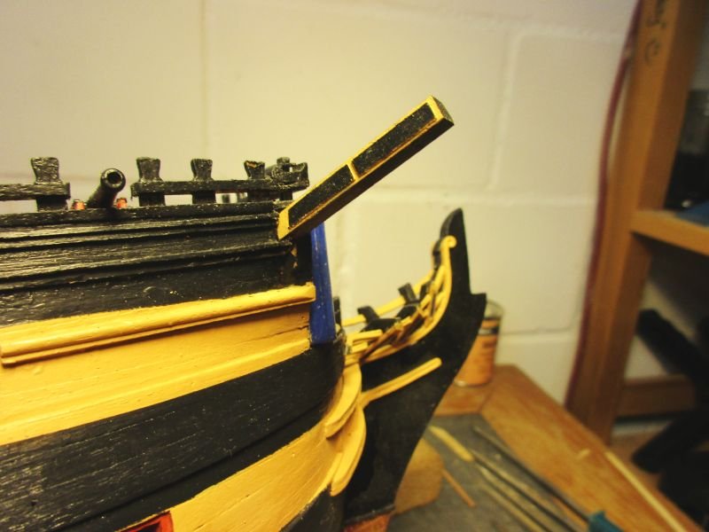
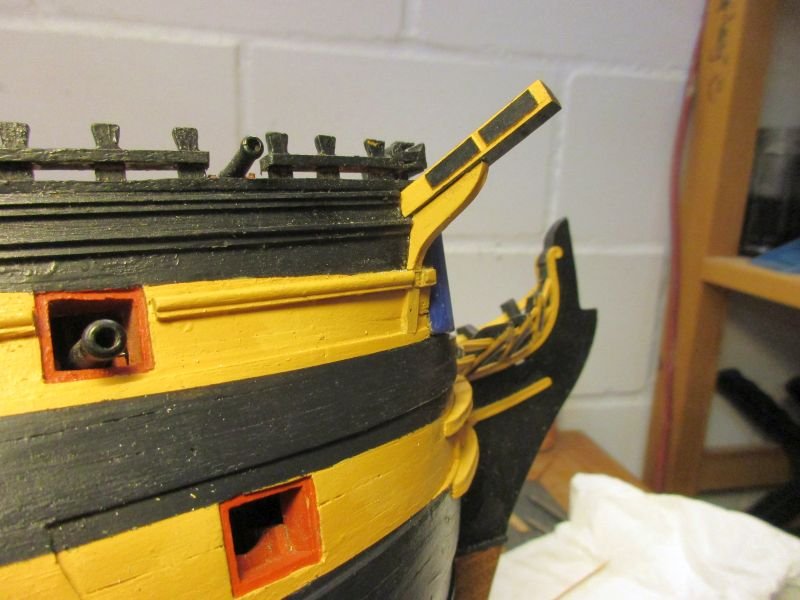
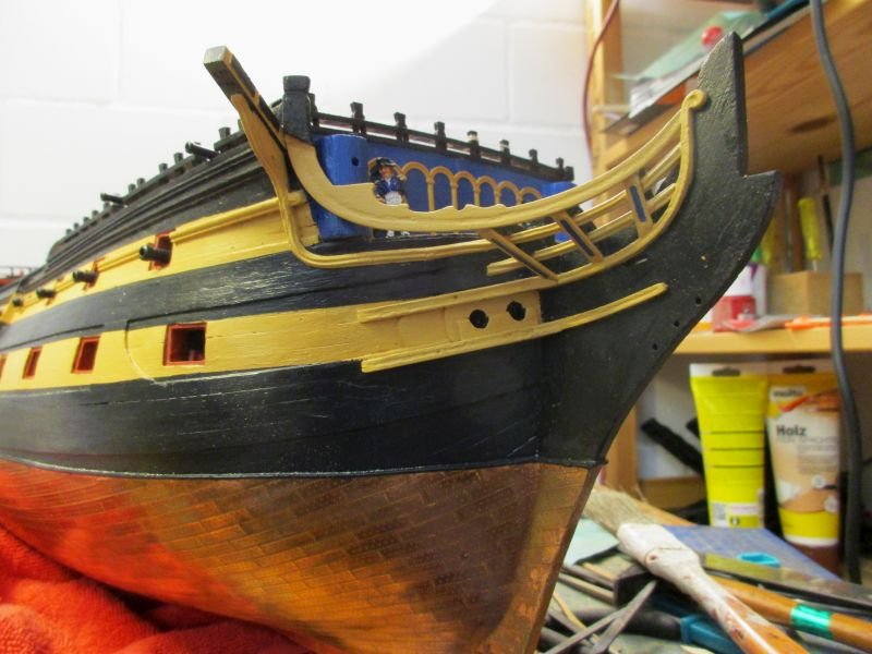
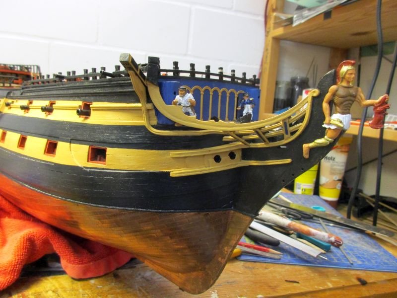
The hawse holes got additional bolsters to give more protection to the lower bow cheeks. Then I tried to attach the cathead. Some corrections were necessary to achieve the required angles forward and upward. Short pieces of leftover deck planks were glued onto the sides to help to create a yellow- black pattern. After painting the starboard cathead, it was glued on. However after installation it seemed much too long, protruding too far. I can only assume that the length is calculated to install it through the bulkhead. So I took it off again and shortened it by about 10 mm and redecorated and painted it. Now it looked more to scale and I could attach the support which had to be reworked first as well, to match the angles of the hull side and the cathead. Then pieces of the white metal profile were bent and put in place to finish the upper railing. Contrary to the instructions I continued the profile over the support and to the underside of the cathead. Several sources show a continuous decoration in this manner. The head rail was shortened a bit to fit behind the upper check rail, painted and glued on. The starboard side was now finished but awaits some rework to smoothen the various bumps. I painted the figurehead, puzzling over the instructions. Finally I decided to provide the hero with a golden helm instead of the bronze as instructed - he deserves it. Also the shin protection is golden, however I'm still unsure about their form and what parts to paint golden. The cast seems to indicate that also the calves were covered and that's strange. The breast was painted brown as instructed. Perhaps he had a light leather armour. The goat's head of the chimera is red, as seen on some illustrations. The still removable hero completes the impression of the starboard bow. a rather strong seaman holds the first variant of the unpainted cathead this looks disproportionate cathead 2.0 with support upper railing finished head rail added the successful hero holds the chimera's goat head - I still don't know, why he didn't take the lion head and what kind of strange weapon he holds in his right hand...
- 366 replies
-
- 11
-
-
- bellerophon
- victory models
- (and 2 more)
-
Admiralty, water based yellow ochre with 15% white. I use the same paint trying to cover my built in flaws - not always successfully, alas. 😳 😊
- 366 replies
-
- 1
-
-
- bellerophon
- victory models
- (and 2 more)
-
Hi Martin Nice to hear from you and thanks for the compliments. Those rails are a white metal profiles, very soft, like tin-solder. And the same is used on the lower transom and side galleries. Cheers Peter
- 366 replies
-
- 1
-
-
- bellerophon
- victory models
- (and 2 more)