flyer
-
Posts
1,016 -
Joined
-
Last visited
Content Type
Profiles
Forums
Gallery
Events
Everything posted by flyer
-
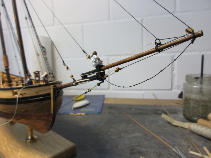
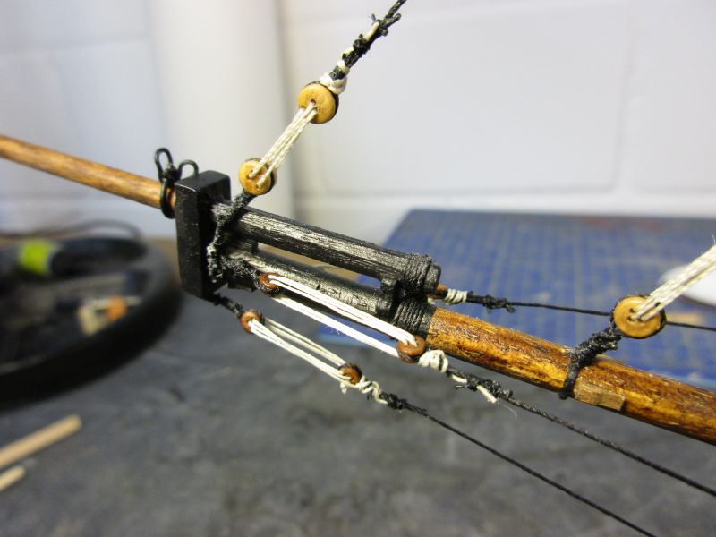
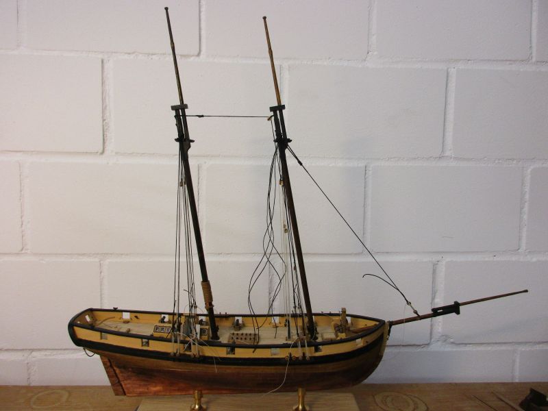
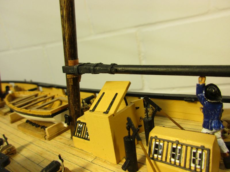
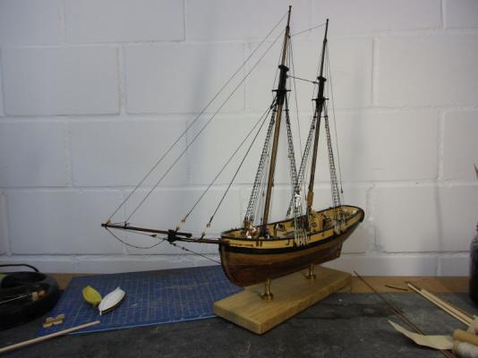
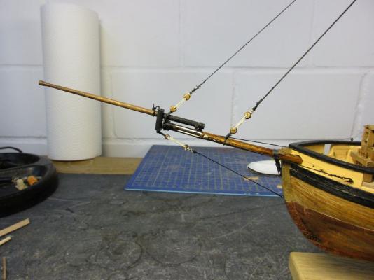
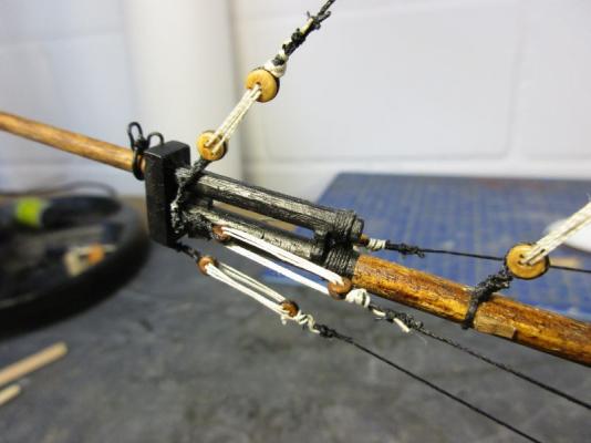
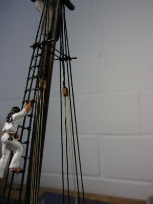
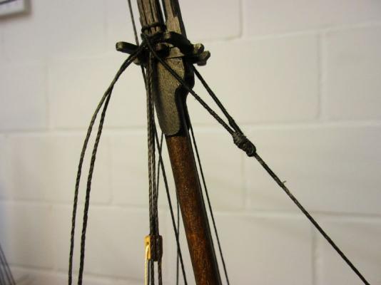
 From now on it was rather plain sailing to finish the standing rigging. One difference to the kits manual are the topmast backstays. They should have about the same strength as the shrouds and I took 0.5 mm black thread to set them up. The jib boom got a footrope for the safety of the sailors working there. And of course the outer jib stay was set up via the traveller. Trials showed than the traveller definitely needed an in-hauler. To keep it simple, I put a 0.1 line in position and belayed it below the belfry. I'm still unsure , if I should replace it by a stronger thread or even add a tackle. Any ideas? Generally I'm very happy with the changes I made. With the standing rigging finished Pickle now shows quite some nice proportions and elegant lines. jib boom with outer jib stay via traveller and its in-hauler the footrope hangs perhaps a bit too loose outer jib stay tackle and in-hauler provisionally belayed The standing rigging is finished - now comes the hard part.
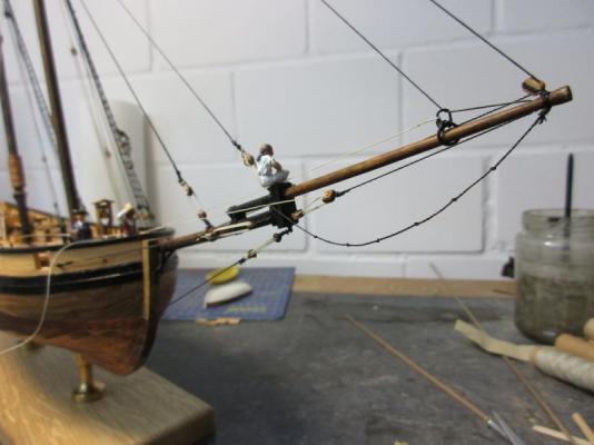
- 293 replies
-
- 8
-

-
- pickle
- caldercraft
- (and 1 more)
-
deadeye strops again Another strop came apart and this time it was beyond repair. I tried but it looked awful and I had to take it out - including that backstay collar which was fixed to that strop. (Oh, I can hear you sniggering there, Mr. Murphy!) One of the spare strops was prepared. This time I soldered it after the deadeye was inserted and glued the whole thing into the slit of the channel with a healthy dose of epoxy. It's probably now the strongest part of the whole vessel - and if I know something about Murphy's law therefore certainly the next one to break. beyond hope and repair... new strop soldered and installed it was worth the effort
- 293 replies
-
- 6
-
-
- pickle
- caldercraft
- (and 1 more)
-
Hi John Badger or Granado? The way your skills are improving, you could do any (or both). I don't know if there is a natural progression. I went from LaGloire (frigate) to Granado (2masted bomb vessel) to Pegasus (3masted, ship rigged sloop) and to Pickle (tiny schooner) - whereof Pegasus was the most complicated also because Pegasus' manual didn't have the same standard as manuals from Caldercraft. The kit itself was excellent. Usually I take the decision for a new kit according to which finished model I would really like to have. And I always ask my wife for her opinion. She isn't particularly interested in ship building but she agrees to live with some the models (we agreed on a maximum of 2 of them in the living room) and has a very good eye for good design. Granado sure is a bit more complicated than Badger but Badger is quite close to Pickle - play it again, John? I also have my doubts about the masting of Badger. She seems a bit top-heavy with those very high masts. A plus for Granado is the available information. There is a book about her in the 'anatomy of the ship' series (ISBN:1 84486 005 1) and there is a original plan available (http://collections.rmg.co.uk/collections/objects/85419.html). Have fun with the decision! Cheers peter
- 293 replies
-
- 1
-
-
- pickle
- caldercraft
- (and 1 more)
-
Spy, I forgot about the replica as an information source. Although the authenticity of the rig is doubtful you can be sure that it works. They fixed a dolphin striker, which I won't, but provides something to stand on below the jib boom. That means for me no bowsprit horses and a single one below the jib boom. Problem solved. Thanks.
- 293 replies
-
- 1
-
-
- pickle
- caldercraft
- (and 1 more)
-
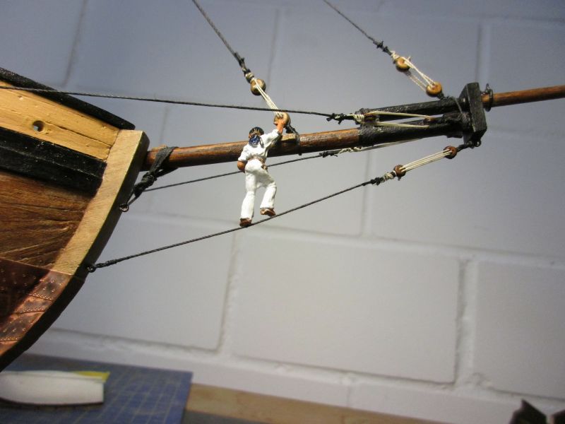
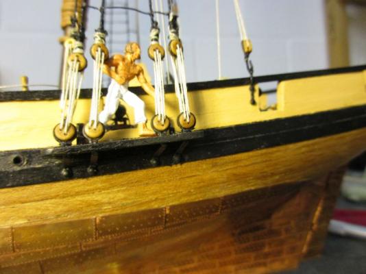
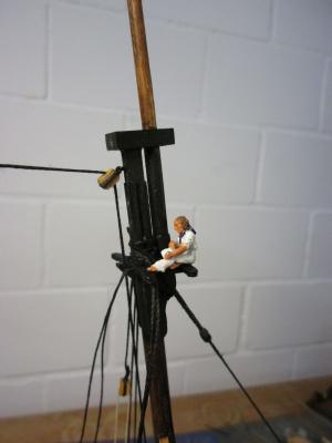
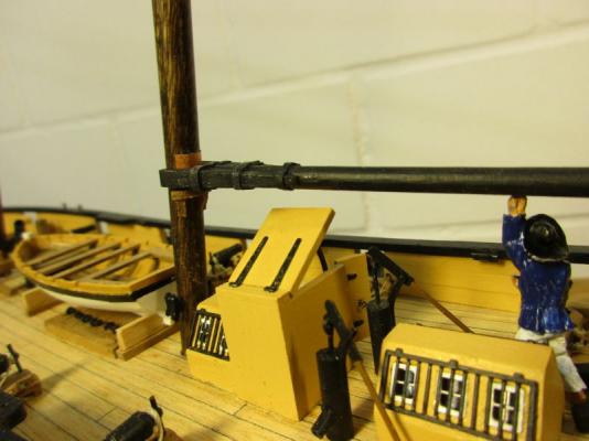
Hi Jason 'less is more' is one of my favourite quotes as well. (If you look at the top of my head it might even be genetically built in.) However sometimes it gets complicated in model ship building. It is not always clear to me if omissions in the kit or plans are because of kit costs, keeping plans simple by omitting self-evident details or because it really wasn't there. One example was the belfry I added on Pickle. I assume any vessel of Pickles size would have a ships bell. But where? And would the addition of a bell be in line with the overall level of detail? The same question arises for the binnacle. Another question are horses on bowsprit and jib boom. I'm quite sure that the jib boom should have at least a single horse. But does the bowsprit need one? You could work standing on the bobstay as one able seaman demonstrates. But if I rig a double horse above the bowsprit (as on my Pegasus) I could also add a netting to stow the jib sail. Or would this be too much for such a small vessel? After my experience with the bees I tend to a simple solution with just a single horse below the jib boom. able seaman Kilmister checking the need for a bowsprit horse (today without hat because of the wind) Cheers peter

- 293 replies
-
- 6
-
-
- pickle
- caldercraft
- (and 1 more)
-
Hi Spy '...and a dog.' reminds me of the famous question: What will be the standard cockpit crew composition in 10 Years? (It came up after eliminating navigator, wireless operator, flight engineer and second officer by increasing automation and duty time.) Answer: One pilot and a dog. The pilot is there to feed the dog. And the dog is there to bite the pilot if he tries to touch anything in the automated cockpit. Now, what might the duty of the dog have been in this cutter? Cheers peter
- 293 replies
-
- 1
-
-
- pickle
- caldercraft
- (and 1 more)
-
Thank you again Spy. Never came across a self acting sail. So far I had to handle them myself. Does it mean that they just let it swing unattended to the other side when tacking? Thanks Nils Hi Martin O'Brians Steven Maturin is a great comfort to landlubber me. And being lazy helps to crafty solutions. Redoing the whole shroud was too much work for me. Thank you Jason. I did put a blob of CA into each slit but it seems that I wasn't generous enough and epoxy holds better. Anyway, CC uses better strops in other kits (Granado for example).
- 293 replies
-
- 2
-
-
- pickle
- caldercraft
- (and 1 more)
-
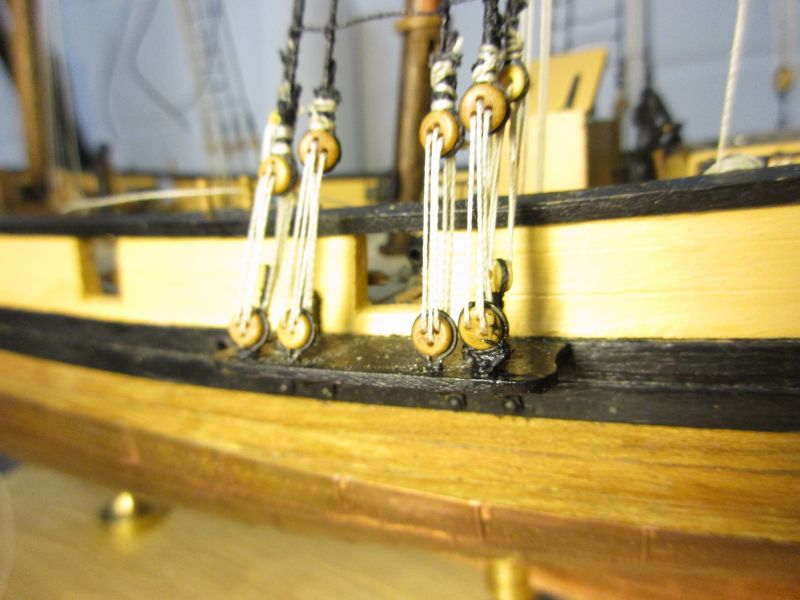
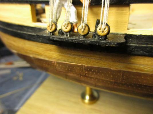
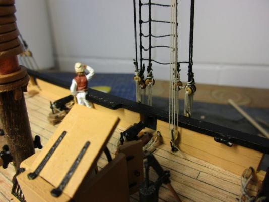
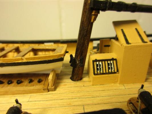
The first of that unique deadeye strops finally came apart and one leg slipped out of the channels' slit. I pulled the strops legs together with a sling of some 0.25 line. Fortunately the problem arose at an outermost deadeye and the botched strop should be sufficiently masked by the topmast shroud's collar at exactly this position. the skipper inspects the broken strop Repaired strop. On this picture I discovered a second one about to brake. This particular construction of the deadeye strops really is unusable and should be changed! The main topmast shrouds were now rigged. They were set up with thimbles according to Marquardt's book. While cross checking with Lees rigging instructions I found that a schooner seems to resemble a ship without a main mast. Lees rigging details suit the most if I take the fore mast as such but Pickle's main mast matches more the description of the mizzen on a three masted ship. shrouds set up with thimbles bees on a schooner While trying to find out how to set up the bowsprit rigging and the jib stay, I slowly came to the conclusion that bees are quite at sea on a schooner. I wouldn't go as far as Jack Aubrey who called them bloodthirsty reptiles and resented them completely when Steven Maturin let his bees fly free in the cabin of HMS Lively but I had to admit that they should go. A little work with knife, file, sanding paper and paint reduced the bowsprit to the simpler appearance favoured in Marquardt's book and the kit's instructions. Now the stay and the bowsprit rigging could be set up according to the manual. reworked bowsprit (bees gone) better without bees

- 293 replies
-
- 9
-
-
- pickle
- caldercraft
- (and 1 more)
-
Copyright - beware
flyer replied to dvm27's topic in Using the MSW forum - **NO MODELING CONTENT IN THIS SUB-FORUM**
How about using scanned cut-outs from books? Occasionally I used in a discussion here such parts of books illustrations to emphasize one point or another. Although I always wrote what book the illustration came from I never had explicit permission from the author. I always thought that I was doing free promotion for those books but I believe now, that I may also have violated copyrights. How do you see that? peter -
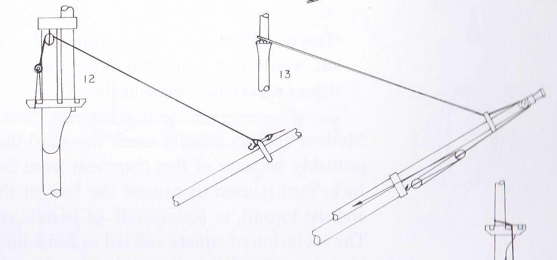
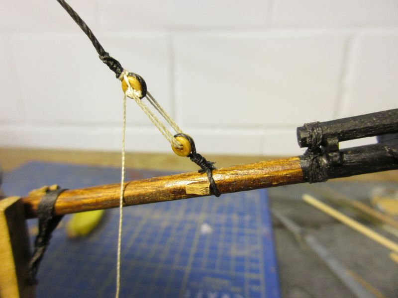
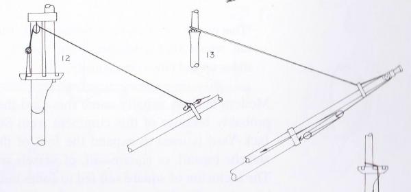
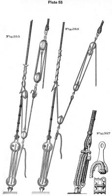
Hi Spy Thanks for the generous information. Strange, setting the jib with a boom. To streamline the discussion a bit, I try to summarize (summarise for those who have the happyness to be one of Her Majesties subject) what I have so far: According to Marquardt there were mainly two traveller forms in use. In the older (12 in the picture) the stay was lashed to the traveller and adjusted with a tackle in the top. An outhauler was led from the traveller to the pulley in the jib boom end and back to the bowsprit cap or bow. The visible hook is for the sail. In the newer version (13) the stay itself was taken through the traveller, the pulley and back inboard and was adjusted with a tackle. This stay was attached in the masttop with an eye splice. Now I assume that the traveller used to travel occasionally or frequently, I don't know. The reason could be a fine tuning of the balance of those fore and aft sails in order to minimise the use of the rudder (to avoid friction, turbulence and slowing down the ship). Especially in the newer traveller version you would need an in hauler because I think just pulling on the jib sail wouldn't do the trick properly and leave the newer traveller constantly trying to move outboard. Spy, on your topmost picture I see two lines leading backward from the traveller, the right (sorry starboard) one perhaps not originating on the traveller but being probably a jib boom horse. Then the line on the port side could be my in hauler. Of course this are just assumptions of a mainly armchair, sailor trying to think logically, mixed with some aerodynamics. (However, I think that hydro- and aerodynamics are quite close cousins, sometimes even tempted to marry each other.) Cheers peter
- 293 replies
-
- 2
-
-
- pickle
- caldercraft
- (and 1 more)
-
Hi Michael Wonderful work! But shouldn't the fiddle blocks hang the other way around? Then the line through the upper pulley could run free of the one through the lower. Cheers peter
-
Hi John Thanks for the further information about the book. But your drawing is fine. Only the run of the stay is not shown. But I think here it was lashed to the traveller and the line we see was the out hauler. This would mean, that we are talking about the older of my two traveller variants. (By the way I understand the traveller is the whole thing including the ring around the bowsprit.). Only in the my drawings the traveller always sits a few meters behind the pulley (which is in the end of the jib boom). Your picture would show the situation with the traveller in the extreme forward position. And this rises again the question how often and how far the traveller travelled. Nils (Mirabell61) thought that it was perhaps shifted to move the balance point of the jib sail in order to balance the whole longitudinal sail trim. This sounds logical but again I have no further information. Your drawing also shows that you could move the traveller inboard by just pulling on the sheet of the jib sail but you would need to prevent it from moving out again with each slackening of the sail. Cheers peter
- 293 replies
-
- 1
-
-
- pickle
- caldercraft
- (and 1 more)
-
Hi John Thank you for the again marvellous pics. I didn't know Petersson's book but from what I see on Amazon it could be helpful. Your description seems to match an older form of traveller where the end of the stay is lashed to the traveller and a separate out hauler is fixed to the traveller and goes around that pulley in the jib boom. I put such a traveller onto my Pegasus and simply ignored the question how the traveller would move inboard. I think that also there the pull goes in the wrong direction if you just pull on the stay because the force would mainly go upward. But on the Pickle version where the stay itself follows the way of the out hauler (through the pulley in the jib boom and with a tackle back to the bowsprit cap) any pull on that tackle would definitely move the traveller outboard. I think I have to rig an separate in hauler. peter
- 293 replies
-
- 1
-
-
- pickle
- caldercraft
- (and 1 more)
-
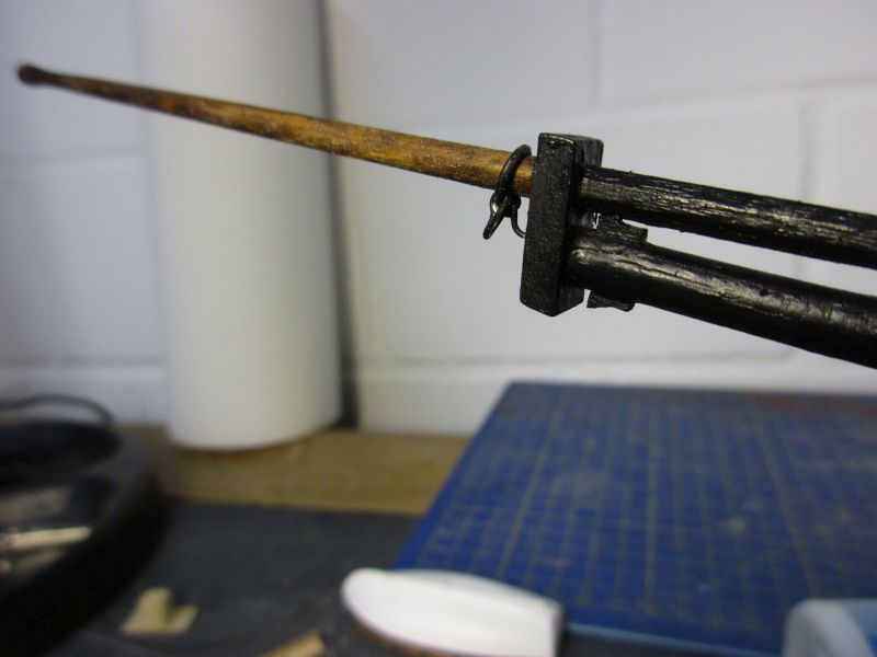
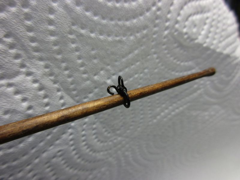
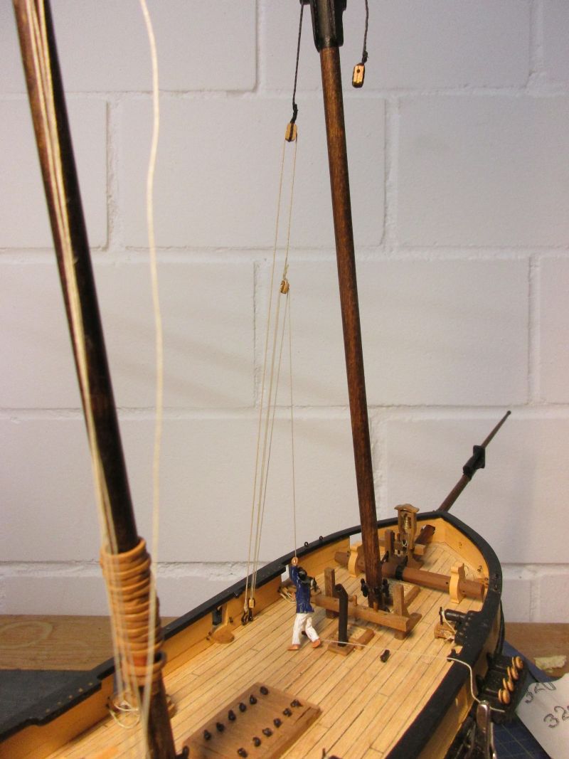
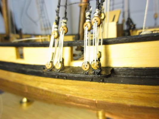
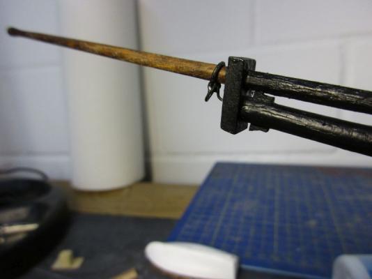
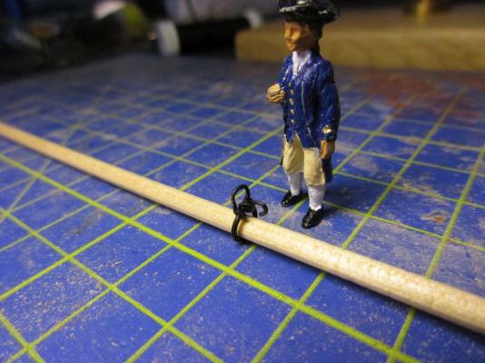
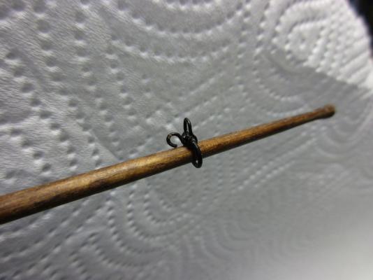
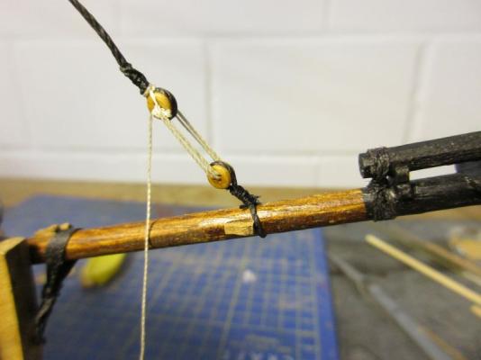
To take a break from knotting ratlines (fortunately there are not so many on this little ship) I turned to the outer jib stay. I distrust the setup according to the kit via that eyebolt near the end of the jib boom and think this is only an approximation of a traveller. A better traveller was made from some 0.7 and 0.5 mm brass wire and painted black. The stay will run under the travellers reel and the hook will be used for the forward corner of the sail. ????? There remains a problem however: I think that the traveller needs an 'inhauler' to fix it in position and to move it inboard when desired. Moving outboard should be possible by tightening the stay itself. But I don't find any information about that. Unless somebody knows more, I will have to make up an 'inhauler' with a short tackle and will fix its standing end with a ringbolt on the bowsprit cap, similar to the stay itself. ????? The future skipper inspects the new traveller Provisionally placed on the jib boom
- 293 replies
-
- 4
-
-
- pickle
- caldercraft
- (and 1 more)
-
Super, super, super Nils! :stunned: :im Not Worthy: :im Not Worthy: :stunned: (By the way - do you already save money for a forklift? In astonishingly short time , I'm sure, you will have finished your KWdG and most probably will need one then to move around that model and it's case.)
-
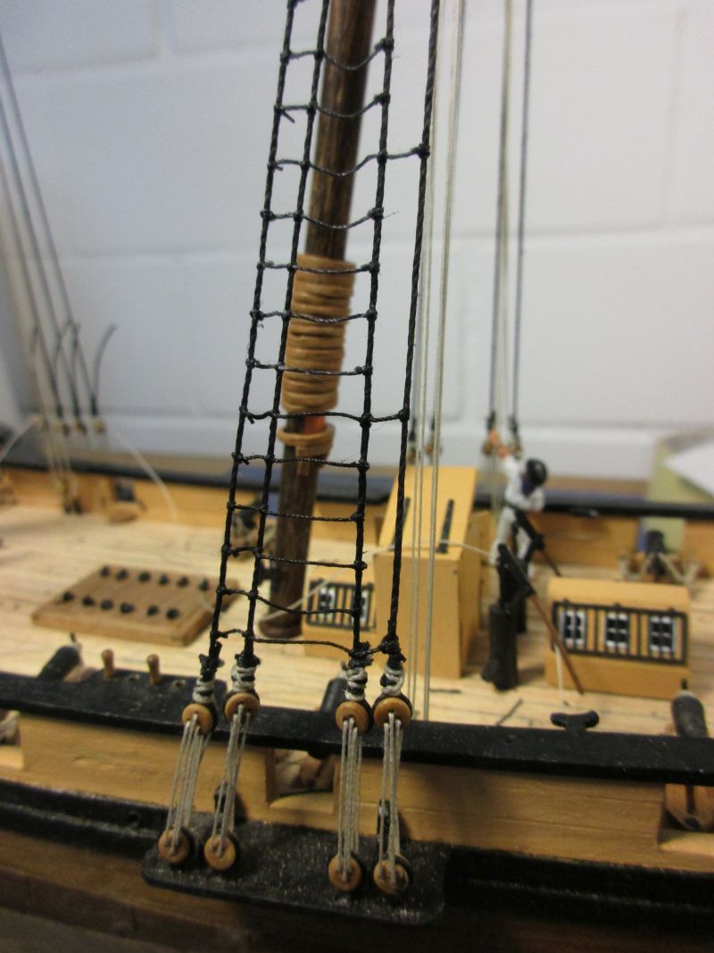
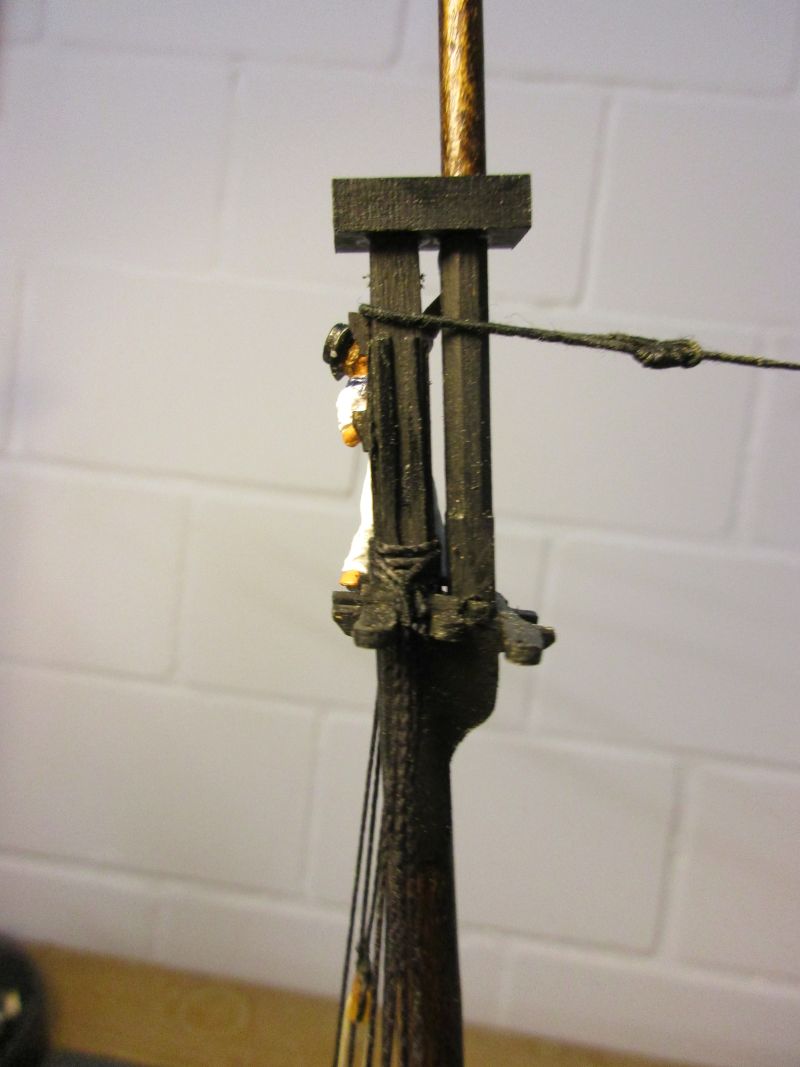
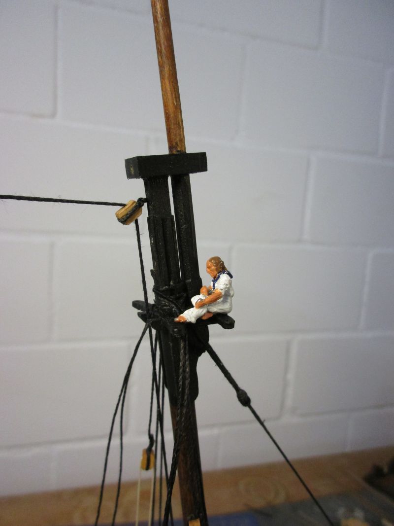
After putting the futtock staves in place they were connected by catharpins. Those are made from 0.5 mm line and two per mast. B.E. did some reflections about how far the ratlines should extend over the shrouds. After considering this and doing some thinking of my own, I decided to rig them in a similar fashion to the Pegasus. Basicaly only the forward 3 shrouds were connected but every fifth ratline was also taken to the forth shroud which is in fact a backstay. Sending an able seaman aloft to test the arrangement showed satisfying results. ratlines The futtock staves will be shortened to the required length after the installation of the topmast shrouds. Upper catharpins are visible.

- 293 replies
-
- 6
-
-
- pickle
- caldercraft
- (and 1 more)
-
Popeye is right about the mast tackles. I tried to find out if there and what was the difference between burton pendants with tackles and mast tackles. In the web (babylon online dictionary) you find the following definition: Burton pendants Definition from Sports Dictionaries & Glossaries Boating & Sailing Dictionaries maritime&shipping™ The first piece of rigging which goes over the topmast head, to which is hooked a tackle, to set up the topmast shrouds. Going through Lees 'The masting and rigging of English ships of war 1625 - 1860' again I see that: - Mast tackles were two a side on lower masts for ships of more than 50 guns, one per side for smaller ships. They were installed on main and fore mast - Burton pendants and tackles were installed, one per side on fore and main topmasts, sometimes on lower mizzen masts and very seldom on mizzen topmasts (only up to 1650). What is shown on your rigging plan are therefore not burton pendants but regular mast tackle pendants. If you want to rig the complete tackle with runners and falls you find the necessary information e.g. in Lees book. Phew, Cheers peter
-
Hi Michael According to my clever books and the web the burton pendants were a tackle which was mainly used to set up the shrouds. I believe they were set on masts or topmasts(!) probably only where no mast tackle was rigged. Lees states: Burton pendants were fitted one on each side of the mast. A single block was spliced in the end up to 1780, after then a thimble was used. They were about the same length as the pendants on the lower mast. Burton falls prior to 1780 had the standing part spliced round the pendant at the head of the pendant block. The hauling part rove through a single hook block and back through the pendant block; it was usually made fast to a deadeye or shroud. When a thimble was used on the pendant, the fall was only hooked to the pendant when required; at other times the pendant was seized to the shrouds. This concerns the topmast burton pendants but I think you could use the information also for lower masts. However the question remains if the version with the thimble in the end of the pendant is the correct one for the construction year of the Vasa. On the other hand you have to consider that Lees mainly writhes about English man of war. And it seems that never more than one burton pendant on each side per mast was rigged. This picture from the web shows the use of the burton pendant. Cheers peter
-
Hi Nils No objections from my side either... I think the asymmetry was built in during the planking and sanding of the lower hull and that up to now I was just lucky because much work is usually done just by visual judgement. Hi Frank Thank you. I really like to work with those Amati copper plates. Hi Spy Ingenious. Thank you very much. Hi Martin The more she takes shape, the more I like her. And I like to think that my alterations also improve the look a bit. Hi Mobbsie You are right. And even rattling down the ratlines is fun in the beginning... Cheers peter
- 293 replies
-
- 2
-
-
- pickle
- caldercraft
- (and 1 more)
-
Hi Hamilton That's a very interesting build you have there and it's coming along nicely. A bit of modification seems necessary but I think that investing some extra wood and some brain power should pay off well for that graceful vessel. I built Mamoli's La Gloire and found it to be the best kit before I started with CC and Victory kits. Presently I'm working on CC's Pickle but for my next build I'm considering Mamoli's America because I'm starting to like schooners, America is almost in scale 1/64 where a lot of extra fittings are available and I like those elegant, elegant lines. Perhaps you would care for some suggestions: To build up the inner bulwark planking you could treat the inner surface of the planks with varnish before gluing them with white glue onto the bulkhead extensions. You should then be able to brake off the extensions after finishing the bulwarks nevertheless and thanks to the varnish the glue shouldn't have penetrated into the wood. Some little sanding should then clean the inner bulwarks again. If this doesn't work it would perhaps be possible to add an extra inner layer of 0,5 or 1 mm bulwark planking to bring its overall thickness to 2 to 3 mm depending on the other layers. This could work if you have a capping rail with a width of about 5mm which covers all that and still would have an sufficient overhang in- and outboard. For the coppering of the lower hull I would recommend Amati's copper hull plates which are available in 1/64 scale, look excellent and are a pleasure to work with. Cheers Peter
-
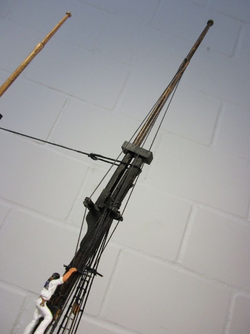
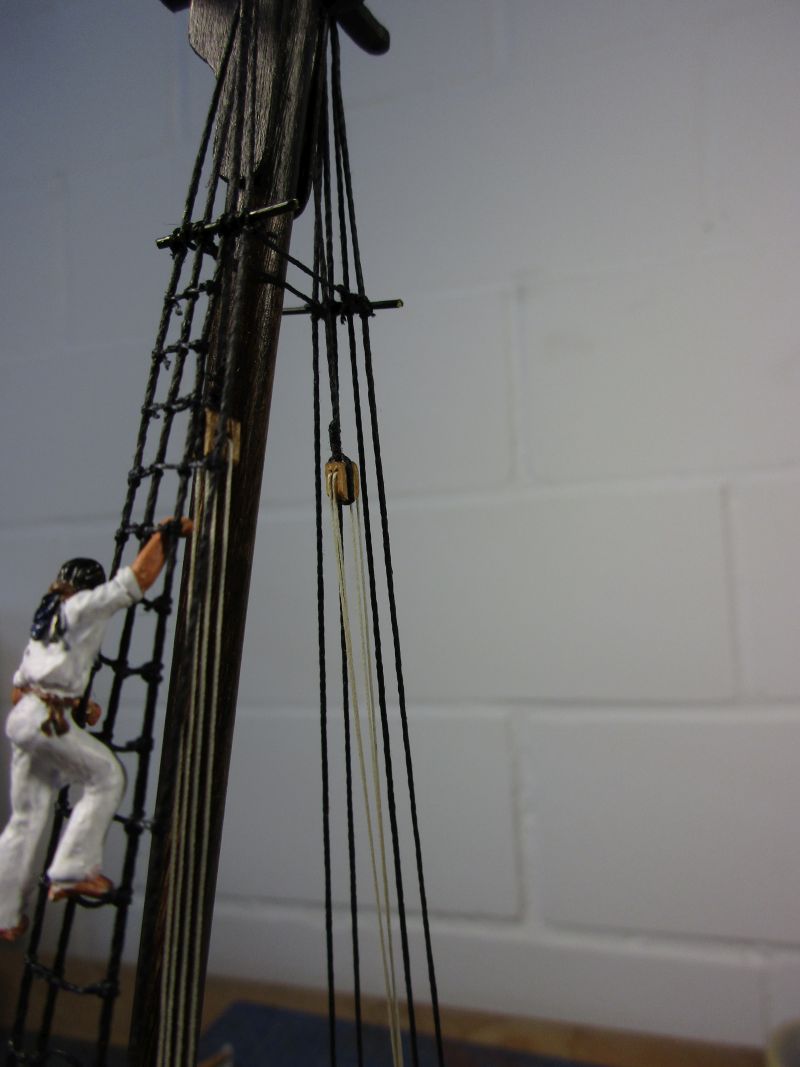
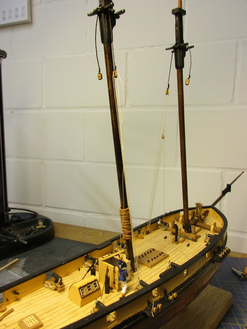
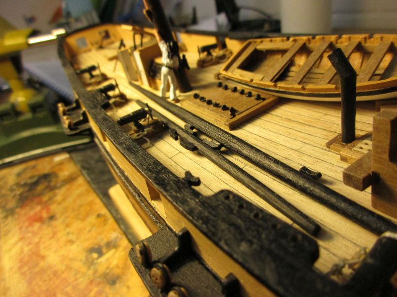
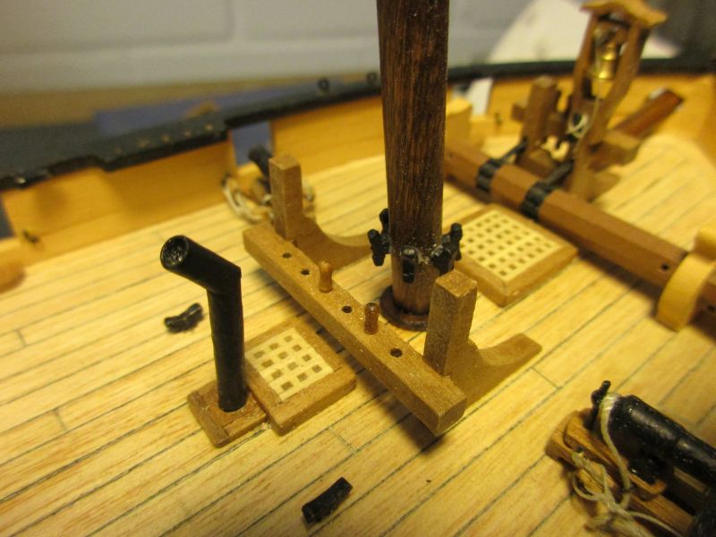
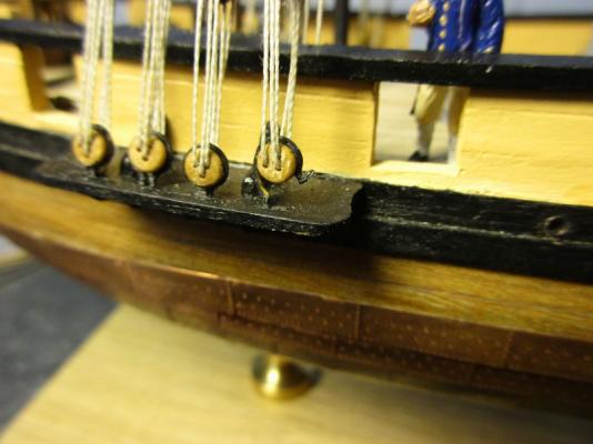
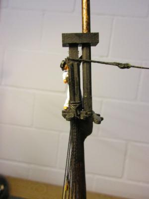
The first parts of the rigging to install, after the bowsprit lashing, were the mast tackles. In the manual I found only the tackle itself but no information about how to set it up. In my clever books different possibilities are shown. On the main mast I opted for a simplified tackle without runner which is appropriate for smaller vessels. On the fore mast however I installed a full tackle with runner because I think this was also used as fish tackle for the anchor and needed more capabilities. the two different mast tackles tackle on the fore mast - runner and tackle block are hooked into ringbolts in the waterway Now I started with the shrouds. As usual I work from aft to forward. The completed mast were stepped in one piece contrary to the way of other builders in this forum which set them up level by level. So far I never had problems to set up the shrouds around the already installed topmasts. After setting up the first two shrouds I usually set up the associated stay to have balanced forces on the mastheads. Because of the changed mast heights the schooner stay now runs almost horizontally between the masts but I find this still looks fine. The mouse is just a asymmetrical figure of 8 knot doubled up on the upper end with a stopper knot. Its easily done and of the right size. The stay, including eye and mouse was seized down to 1cm below the mouse. The fore stay was set up with deadheads according to the manual although probably heart blocks would have been more true to the original. The collar on the bowsprit is held in position with two stop cleats. main top taking shape fore top with schooner stay fore stay collar of fore stay the nearly horizontal schooner stay seems to look ok


- 293 replies
-
- 7
-
-
- pickle
- caldercraft
- (and 1 more)
-
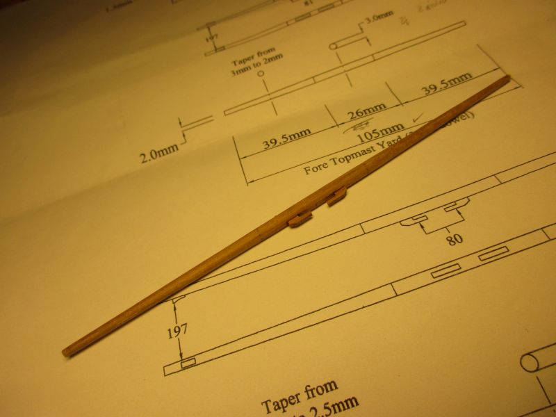
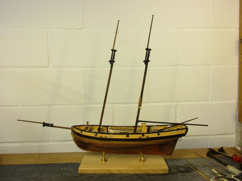
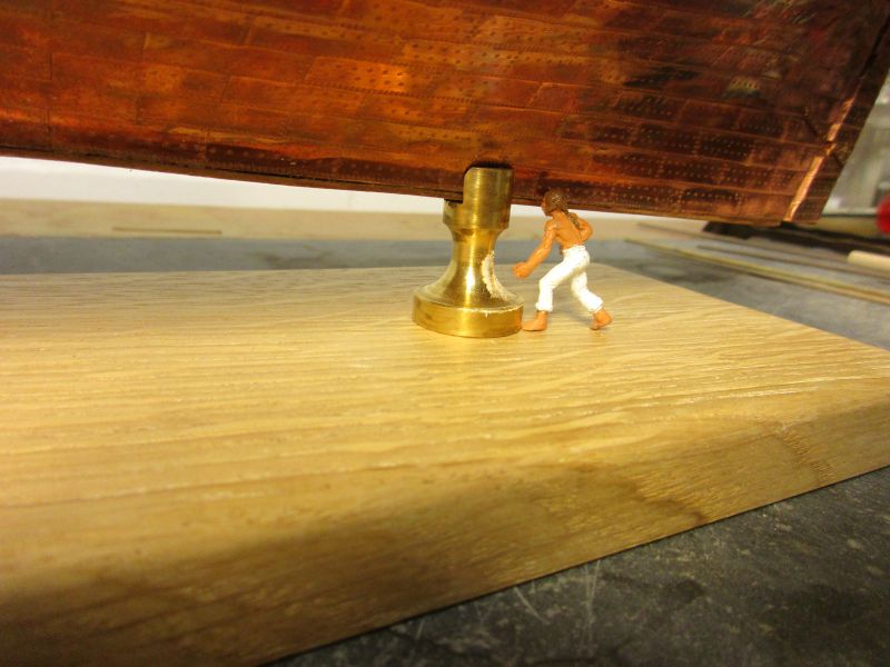
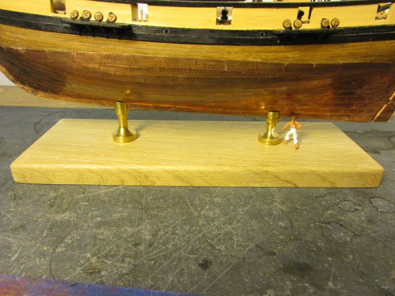
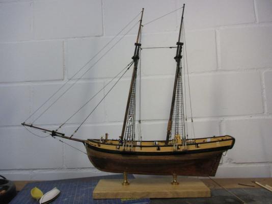
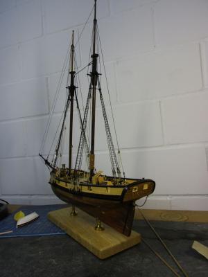
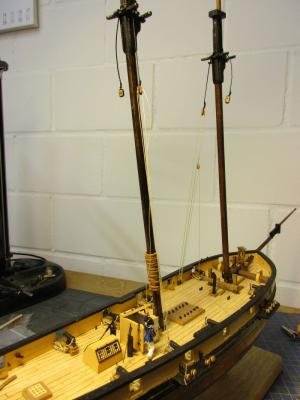
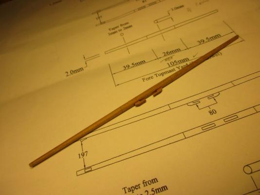
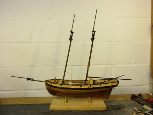
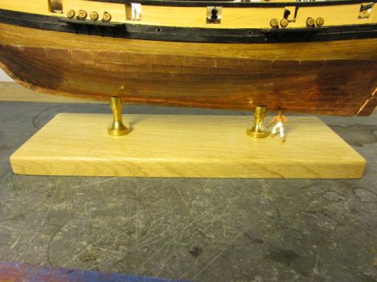
The two yards were now each made with an octagonal mid section. I had to use thicker dowel respective a square strip to make this possible. fore yard in the raw both yards on deck - the stopper cleats on the ends are still missing Recently the future skipper of Pickle was visiting the wharf and asked for a better progress in finishing his vessel because of some urgency (he probably was just impatient). He also cited the old saying that 'Planning is just the replacement of coincidences by errors' and mentioned that he had a moderately experienced bosun available for the installation of the rigging as well as a reliable carpenter for possible modifications. I took a deep breath, plunged into deep water, stopped planning all that belaying points and stepped the masts. foot of main mast foot of fore mast After setting up the masts perpendicular to the deck I found that Pickle was listing visibly to starboard. That impression was confirmed by the admiral and other bystanders. First I thought that a vessel hardly ever lies on an even keel and the listing could be in accordance with the set sails and the apparent wind. But this would just have been a (too) easy way out. I had to correct it. Sigh. After about 7 tries which included remounting Pickle the other way on the stand, reworking the holes in the stand, changing the screws and drilling new holes into the keel I found that the a slightly asymmetrical lower hull was pushed into a listing position by the symmetrical brass columns on the stand. Reworking the brass finally did the trick. (It seems that if you want to put things straight you have to cut some of the top brass.) there was the crux of the matter...


- 293 replies
-
- 8
-
-
- pickle
- caldercraft
- (and 1 more)
-
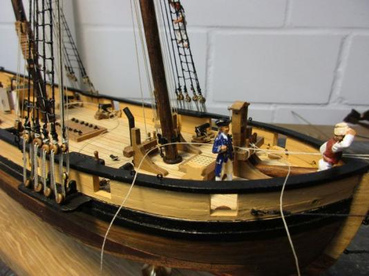
Hi Nils Yes, this 'dry dock view suddenly makes the little Pickle quite impressive - I was surprised myself. Hi Mobbsie The credit for those bars goes to Caldercraft - they are included in the kit. It's a good example for the mixture of excellent details, strange solutions (the deadeye strops) and little shortcuts (like the missing octagonal section on the yards) in that kit. But it is still a great one. Hi John My launch is still here, I checked. But it couldn't be mine anyway because I don't have such portly gentlemen in my crew (because all the food goes to myself). I tried to find out what uniform he wears. Could it be a lieutenant's? But those are great pictures, full of details like the shroud plates or the way the swivel gun is mounted. Hi B.E. You are right. I will have to improve those boat chocks. Once again the picture shows clearly what you try to overlook with the bare eye. Sigh. Cheers peter
- 293 replies
-
- 2
-
-
- pickle
- caldercraft
- (and 1 more)
-
Wonderful pictures, John. In this case I was wrongly blaming the kit designers for just skipping some belaying points. But I think I spotted a free pin in one of the shots! peter
- 293 replies
-
- 1
-
-
- pickle
- caldercraft
- (and 1 more)
-
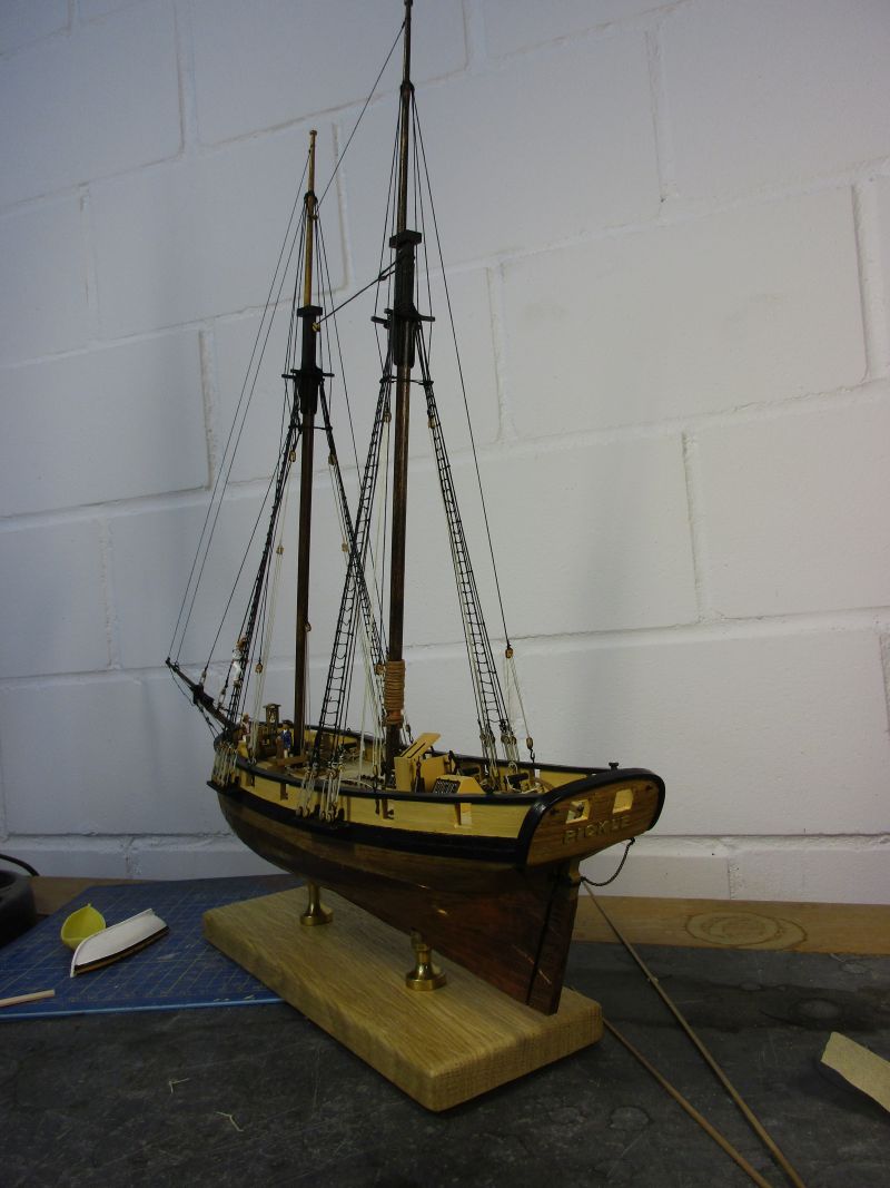
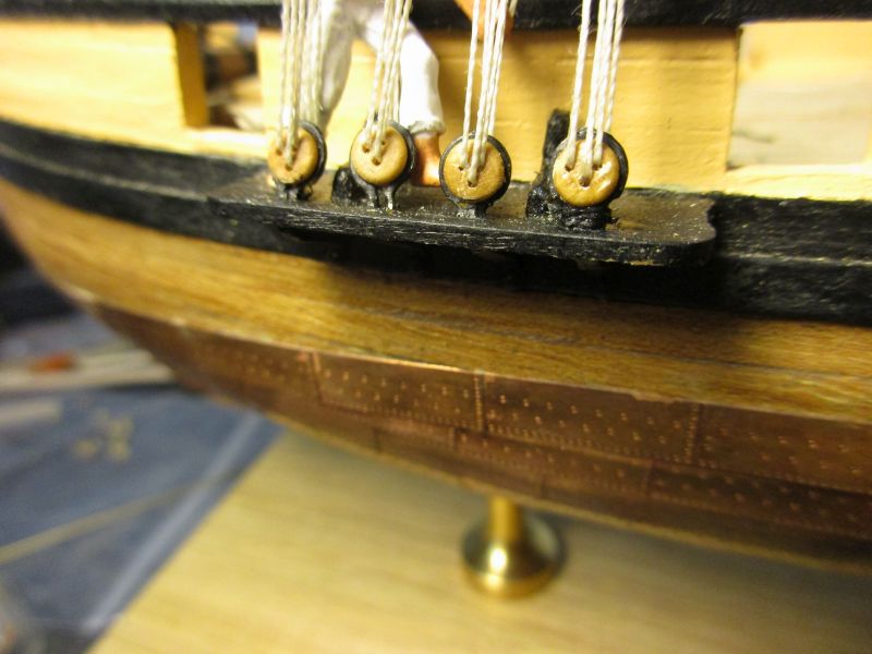
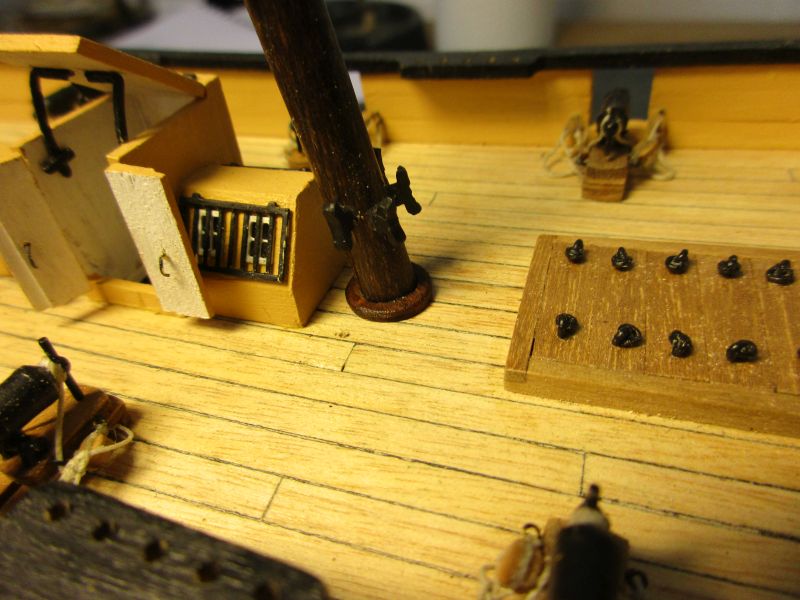
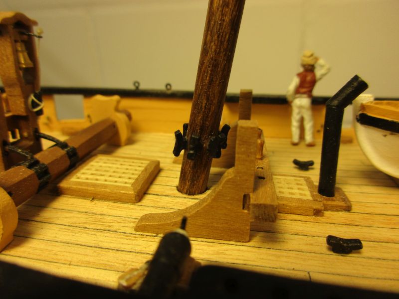
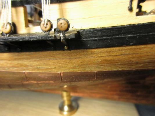
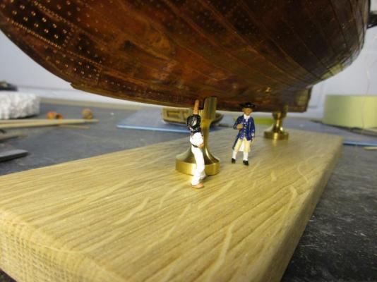
While working on the remaining spars I also continue preparing the masts by adding blocks, cleats and ringbolts. The boom saddle on the mainmast is in place and some copper sheathing to protect the mast is also attached. I haven't yet completed the belaying plan but experience says that you never have enough belaying points in those kits and therefore I put 2 additional cleats onto each mast foot. Pickle is fixed on her stand. I used an oak plank from the local wood shop and two Amati brass columns of different heights. Those needed reworking a bit with a file. I opened up the slits to 5mm and adapted the top to the angle of the hull side. All is held together with 2 long screws through base, columns and into holes drilled up through the keel. boom saddle with copper sheathing additional cleats on mast feet that brass column needs some polish... stand She swims! (Not actually but somehow virtually - I like the lightness of that stand.)


- 293 replies
-
- 6
-
-
- pickle
- caldercraft
- (and 1 more)