


flyer
-
Posts
1,016 -
Joined
-
Last visited
Content Type
Profiles
Forums
Gallery
Events
Everything posted by flyer
-
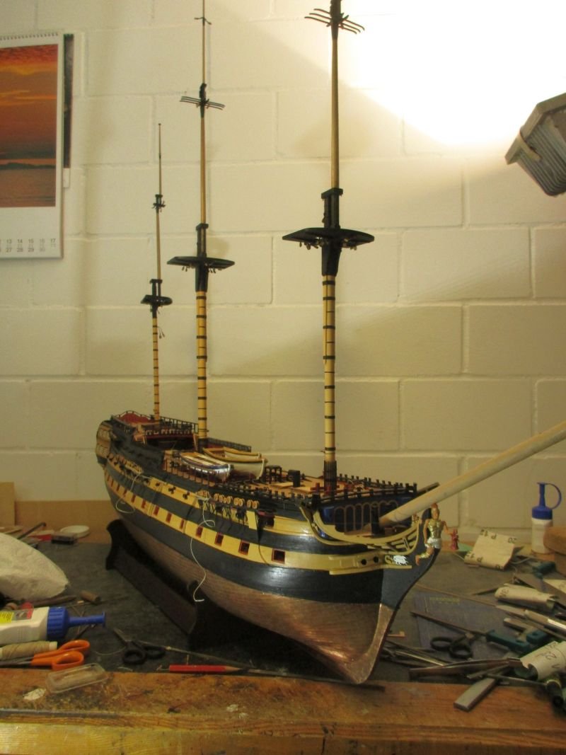
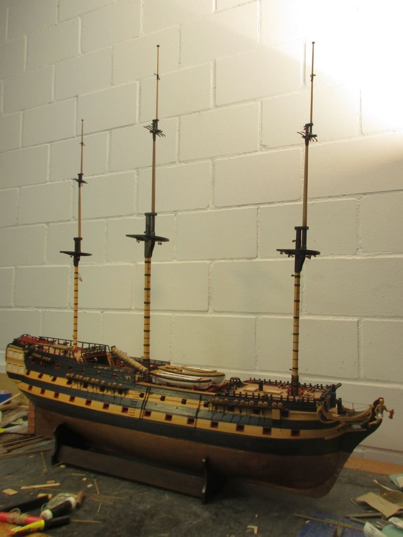
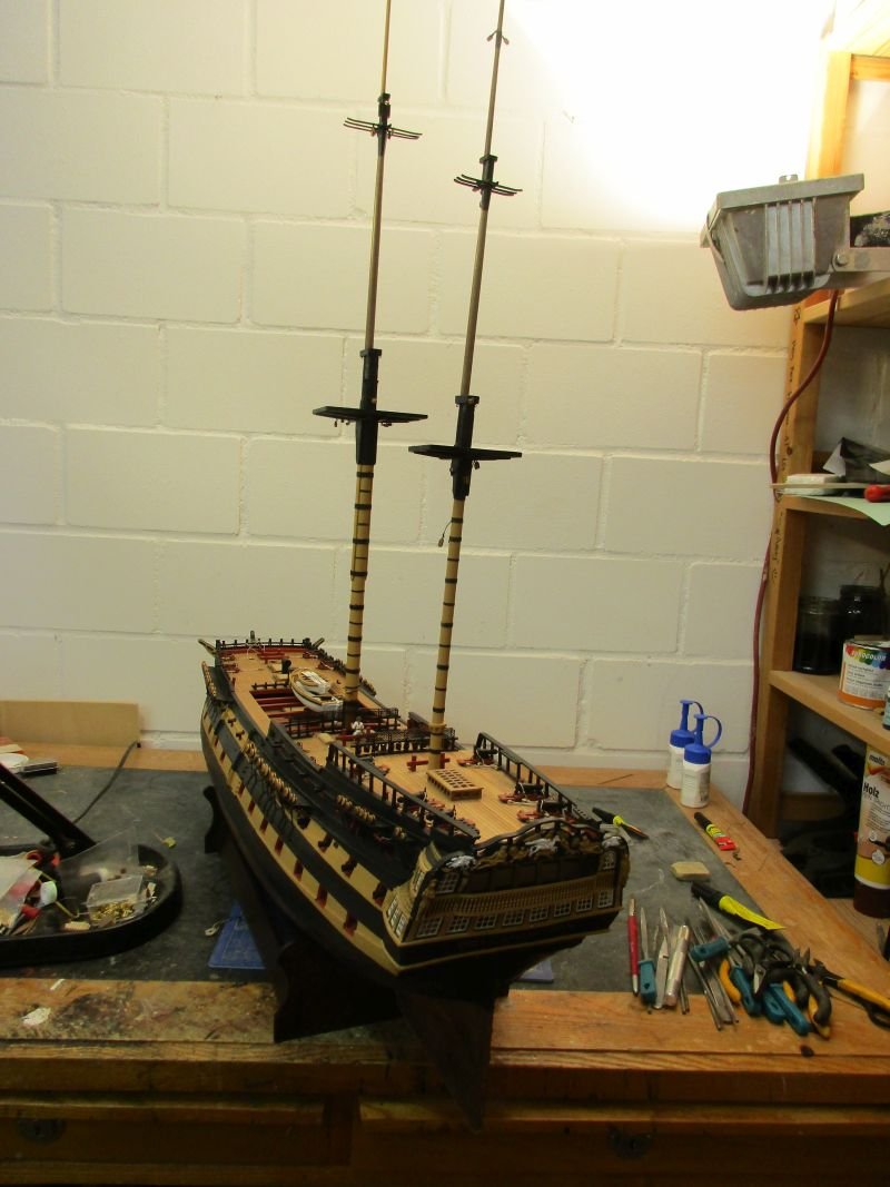
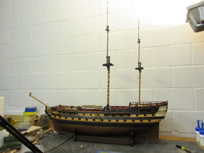
 Fore mast The fore mast and its yards were made similar to mizzen and main. While working on them I realized that about now it was time to put in those sheets which led through the sheave blocks and are belayed below the gangways. Anyhow I have to think about how to fix the boats on the beams. It seem advisable that they should be easily removable during setup of the rigging and perhaps even on the finished model to facilitate cleaning or repair work in the waist. sheets belayed below gangway the 3 fore yards all 3 masts provisionally stepped I'm having problems to place the whole model into one picture - still clueless where and how I shall place it when finished...
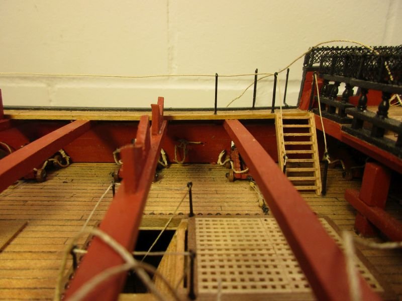
- 366 replies
-
- 10
-

-
- bellerophon
- victory models
- (and 2 more)
-
Hi Michael After silently admiring your build for a while I have to say how much I like it. Not only your unique realistic style shows but the added details depict again a masterpiece in the making. The arrangement of the (too many?) guns below the fore castle left some doubts but I think EJ_L not only shares them but also shows a good solution. Not every gun port was always filled with a gun and leaving one pair off seems good to me. In post #86 I see some scuppers. Did you drill them through to the outside? Great work! Cheers Peter
-
Ships vs Boats
flyer replied to Mike from Aus's topic in Using the MSW forum - **NO MODELING CONTENT IN THIS SUB-FORUM**
Keith, here is a question for the expert: When Sully made his virtuoso landing on the Hudson, did he convert his aircraft into an airboat or an airship? 😉 Peter -
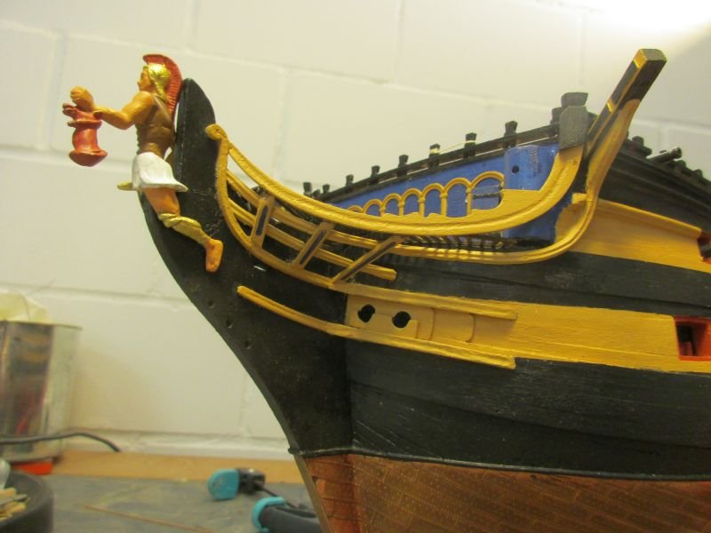
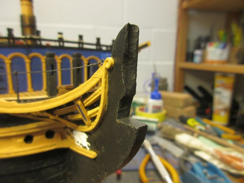
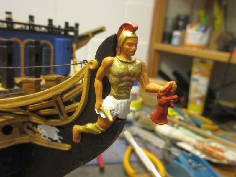
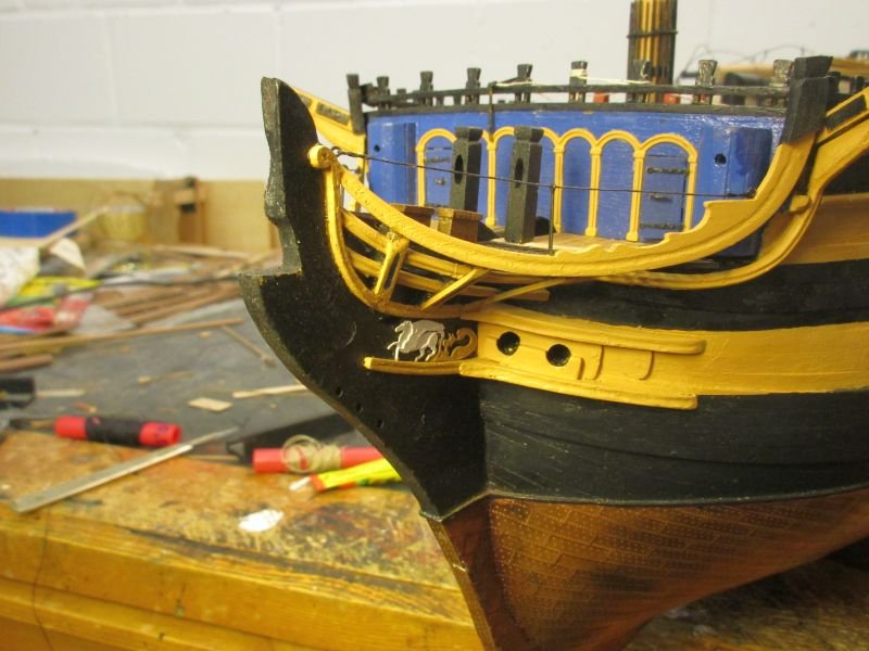
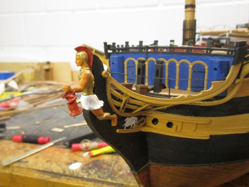
Bow and figure head While working on the foremast and yards I frequently came across the figure head and realized that some additional work was required to 'marry' Bellerophon properly with the bow. Sitting on the simple step it looked more like a randomly placed passenger than a quite important part of the ship. I started to gnaw at the bow with various instruments (file, Dremel, knife etc.) to make a snug seat which allowed back and head to be in contact with the bow. I'm sure those figures needed a tight sit as they were exposed to quite some weather. Bellerophon is still provisionally attached. With the final fixing I will see that no light will pass between bow and figure, making it more an integrated part of the bow than just an addition. Bellerophon sitting rather exposed on the unmodified step modified step better fit much better foremast is ready, still working on the yards
- 366 replies
-
- 8
-
-
- bellerophon
- victory models
- (and 2 more)
-
Hi Mark She's looking great. The damaged grating at the bow... well, welcome to the club! (I somehow fiddled some 1x1mm strips into the place of the broken parts.) Cheers Peter
-
Hi Martin It's great to see you back in the wharf. Maybe you could still use those supporting columns with longer screws, reaching well up into the (as I hope) plywood keel. Nice co-worker. He looks quite intelligent but he might perhaps be not too handy with delicate work. Cheers Peter
- 467 replies
-
- 1
-
-
- fly
- victory models
- (and 1 more)
-
Now, I'm a bit confused. I believe Spy has a lot of experience with actual sailing more modern craft but... As far as I can see in my various sources, the lower mast was usually held back sufficiently by the shrouds while backstays were used to stabilize topmasts or topgallant masts. Setting up backstays to the lower mast would unnecessary complicate the rigging and the handling of the vessel while adding e.g. an additional pair of shrouds would be a much simpler solution. I'm just a landlubber but Dr PR's diagrams in his excellent link seem to confirm my doubts. Spy, could you dispel those doubts? Cheers Peter
-
Hi Mark Wonderful clean work. Regarding Franks question: I did put a simple chimney into the opening of the binnacle but when I just tried to see it below the overhang of the poop It was just barely visible and only because the rigging is not yet in place... Cheers Peter
-
Hi Tom Fix the finished yard horizontally, soak the footropes with diluted PVAC glue, hang clips in regular distances onto the footrope to create a natural hang and let dry. I could include a picture when building the next yard. Cheers Peter
- 366 replies
-
- 1
-
-
- bellerophon
- victory models
- (and 2 more)
-
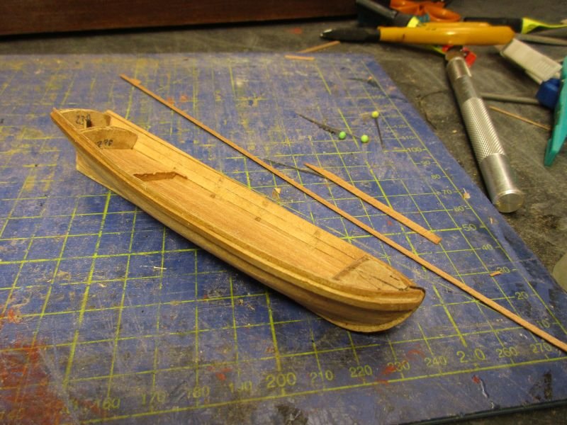
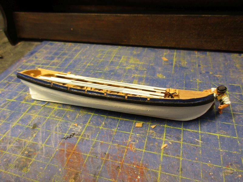
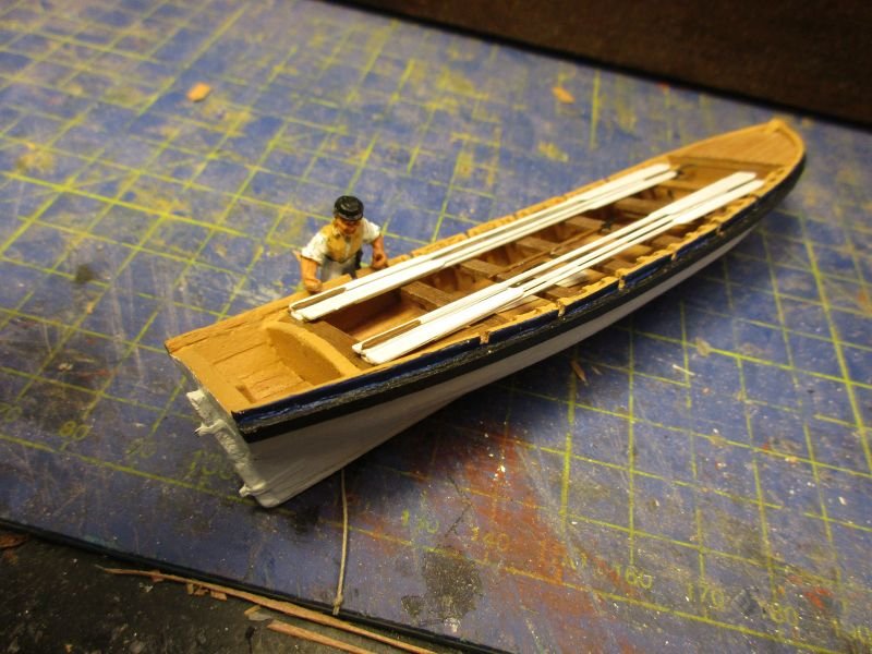
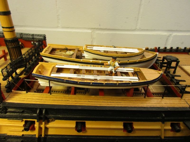
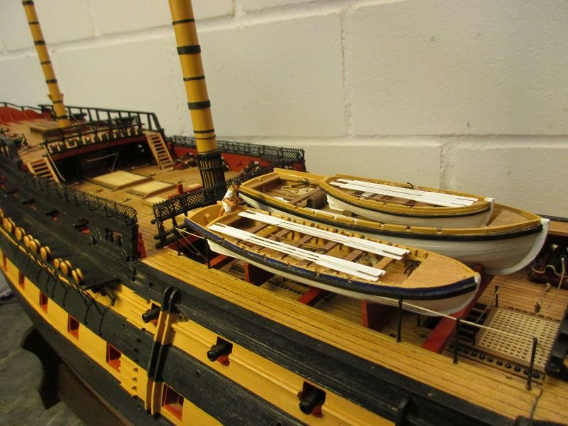
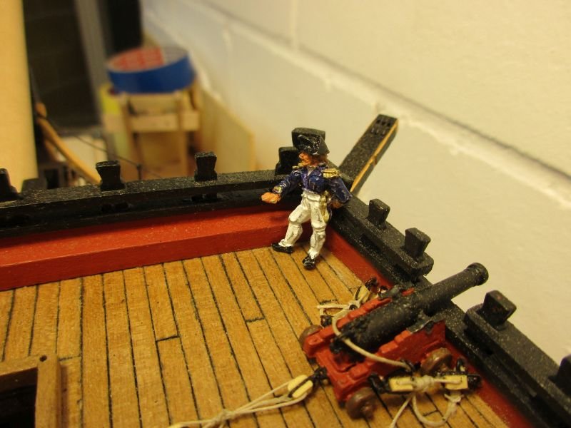
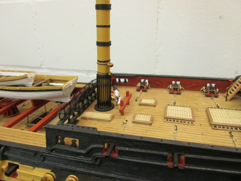
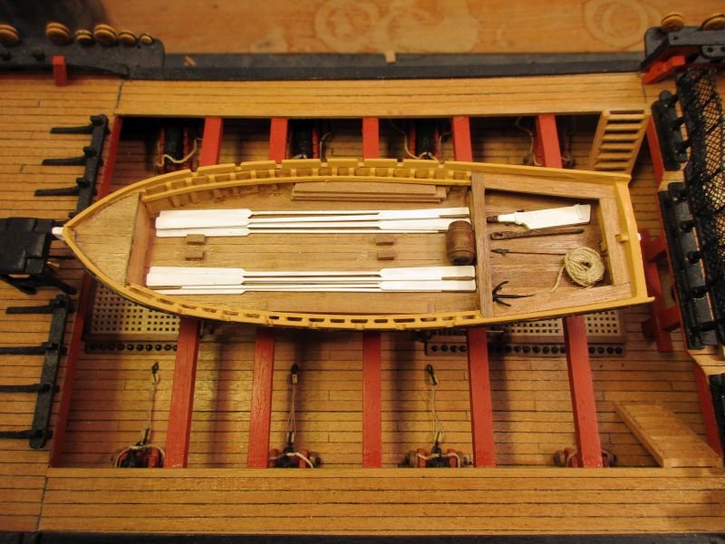
32 foot barge Alternating between building one mast and one boat was a good idea. That way I generally look forward to building the next mast or boat and enjoy the change. And building that many boats actually is fun. It's fascinating how one can form all those different small hulls with relative simple means. One of the problems of those boats - the floor set too high - was overcome this time by reworking the bulkheads to set the floor lower and then thinning the floor itself. For floor planks I used again 0.5mm planks cut to a width of 2mm. On the third try the inner depth of the boat now looks acceptable. The barge was finished again with an additional rudder (placed inside) and its gudgeons. When placing the barge on the beams I found not enough room between the launch and the rail on the inner side of the gangway. It seems that the skipper ordered slightly too large boats. Leaving off some of the stanchions was a solution which could work on the prototype as well. barge with planked floor finished and equipped barge barge on the beams - the rail should be sufficient, despite the partly missing stanchions the coxswain is checking his work place
- 366 replies
-
- 8
-
-
- bellerophon
- victory models
- (and 2 more)
-
Hi Pete Welcome to MSW. Pickle is a wonderful subject. The prototype is not really well documented, so you have a certain liberty how to finish the model. Bruce's suggestion is a good one. Don't forget to start a build log. That way you will get a lot of help and motivation to carry you on. Have fun! Cheers Peter
-
Hi B.E. Two fantastic builds and a very well earned glass of wine. Cheers! Happy new Year and stay healthy. Peter
- 261 replies
-
- 4
-
-
- muirneag
- vanguard models
- (and 2 more)
-
Hi Michael Thank you, but it's just the ingenuity of the kit. The yard end cap with its two arms is one etched part. You just bend the arms at 90°. The end ring (which should be broader, but is an usable approximation) is a second part together with its arm. There you bend the arm and stick its end into the hole in the middle of the end plate of the first part - after deepening that hole carefully into the Yard. The two iron bands are strips of cartridge paper glued on. Then paint all black and voilà. The inner ring is similarly constructed, also of two parts. I know a bit of soldering. That would be quite easy especially if you don't have to worry about cold junctions. However such brass parts should better be brazed for stability and that's a bit trickier. Anyhow I think you don't need to worry about stun sail boom irons for now. I believe they came into use in the middle of the 18th century. Cheers Peter
- 366 replies
-
- 2
-
-
- bellerophon
- victory models
- (and 2 more)
-
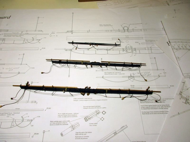
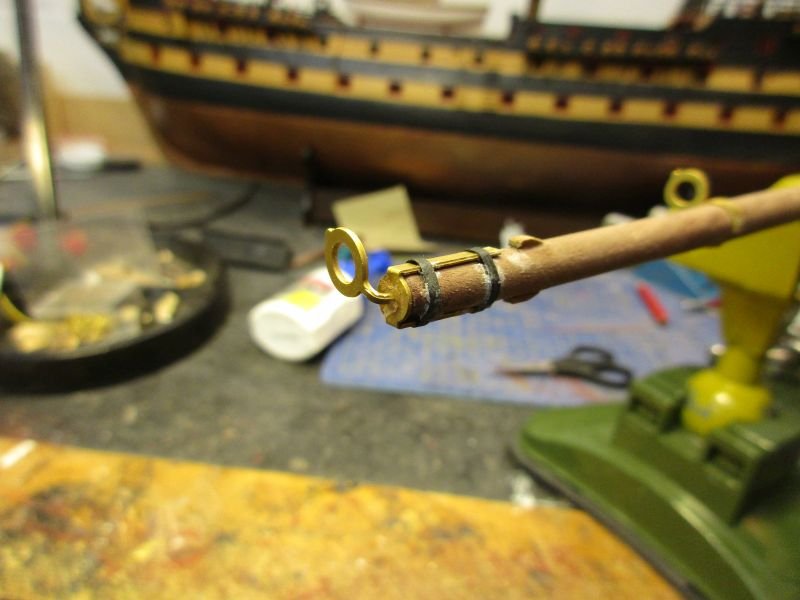
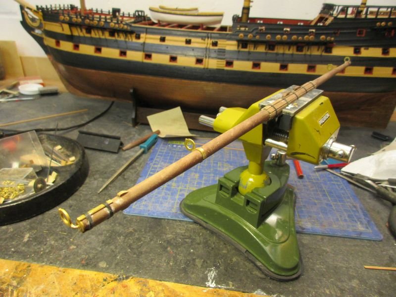
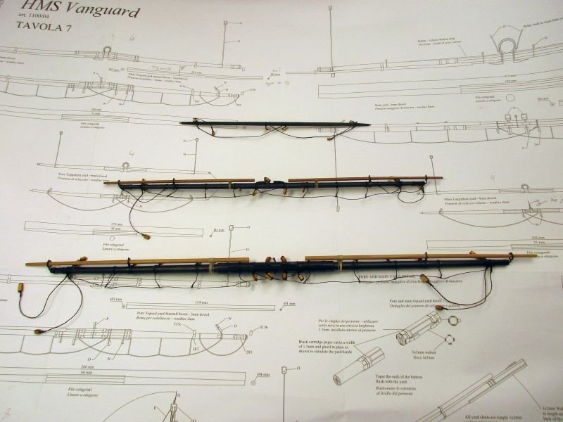
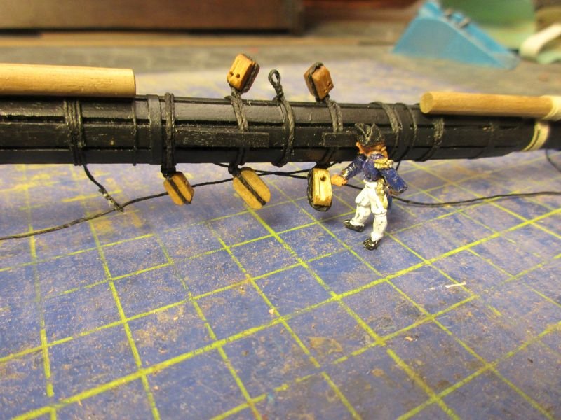
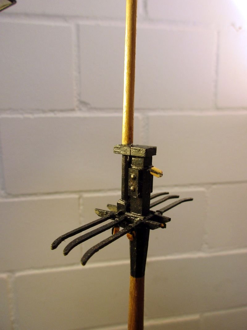
Making the three yards was time consuming. The main yard is huge - it's as long as the lower main mast. According to Lees, the prototype yards are made of one piece of wood, if possible. If no suitable wood was available, e.g. the yard was just too large, then it was made of two parts, joined in the middle. That joint was strengthened with battens. Obviously for the original ship it would have been difficult to find such a single piece of wood to make a main yard. So I simulated a yard made of two parts with battens strengthening the centre. But I put on eight battens contrary to the arrangement with only 4 according to the plans. As I understand Lees, only spars which were made of two parts did have battens, but then eight of them (or 16 in case of the crossjack). The topsail yard and the topgallant yard are supposed to be made from one piece of wood each, so no battens were added. Attaching all the blocks, footropes and stun sail booms was done according to the plans. yardarm of the main yard with stun sail boom irons main yard finished main yard compared to the mizzen mast center of the main yard main topsail yard main topgallant yard all three main mast yards
- 366 replies
-
- 5
-
-
- bellerophon
- victory models
- (and 2 more)
-
Hi Martin What trigonometry is for one, is a Language for another. Although I love the French, I never mastered their language. It consists only of irregularities! On the other hand trigonometry seems quite straightforward once you found somewhere a right angle. So whenever I have a problem, I start to look for right angles - but never found one in French. Good luck with your new shipyard! Cheers Peter
- 366 replies
-
- 2
-
-
- bellerophon
- victory models
- (and 2 more)
-
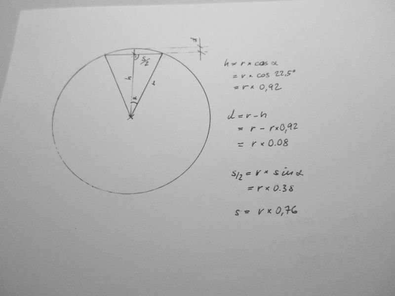
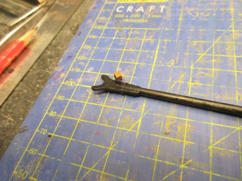
Forming the octagonal centre section of a yard Nearly all yards have an octagonal centre section. Especially where no battens are used to strengthen the center section (according to Lees' Masting and Rigging of English Ships of War all yards which were made of just one single piece of wood) I wanted to make the largest possible octagon out of the given round dowel. To find how, I used some half forgotten trigonometry: Starting with filing the first plane which would form the first face of the octagon I had to find out how much to reduce the dowels diameter and what width I could expect. (α is half the centre angle of one face of the octagon. That is 360° : 8 = 45°. Thus α = 22,5°.) On a 4mm dowel for the main topsail yard I had to reduce the dowel by 0,16mm. The face width is about 1,5mm. After filing that face I turned the dowel by 90°, filed a further face an so on, until I had a square with four very round corners. Then I turned it by 45° and repeated the process. Fortunately my vice has a convenient opening to hold a square with its edges upmost. After finishing the centre section I had of course to rework the ends to get the necessary tapering. A tapered octagon was filed and with the yard put into a simple drilling machine the outer parts were worked round with sanding paper. That way I got a topsail yard with a width of about 3,7 mm over two opposite octagon faces out of a 4mm dowel. It's not as complicated as it sounds and you could use the same principle to form the centre section with a milling machine (and the ends with a lathe).
- 366 replies
-
- 5
-
-

-
- bellerophon
- victory models
- (and 2 more)
-
Hi Michael Have just found your newest masterpiece being built. I love it. She's already looking great and definitely bearing your trademark. Those dummy carriages are again a tremendous improvement. Cheers Peter
-
Hi Bob Fantastic work and excellent looking rope work on your Granado! Checking on my Granado I think that most of the ropes belayed to the breast rail do need some extra length to be properly usable e.g. braces when yards are braced up. These ends I did somehow coil around the rope itself which may not be correct but was what I could think of at the time. the lower part of that picture shows the breast rail Cheers Peter
- 421 replies
-
- 4
-
-
- caldercraft
- granado
- (and 1 more)
-
Hi NotsoObviousNewby You're doing really tremendous work on your build. Regarding your questions I would say: - Option B - The feature with a beam across the deck linking the catheads is something I find only on ships of the line where that beam also forms part of the forward bulwark of the fore deck. I'm not quite sure if its main use is strengthening the catheads or just stabilizing the forward end of the deck or both. That beam - painted red - is shown by the skipper on my Bellerophon. It is level with the catheads. However I didn't find such a construction on frigates and smaller vessels, where the catheads usually lay diagonally to the deck beams and lead trough the deck perhaps to be fixed below the deck beams. I'm not sure about the exact construction as all my clever books are somewhat vague about it. OCCRE perhaps isn't always true to the original and may have something mixed up here. - If you allow me to criticise something which irritates me quite strongly and will also irritate you as you improve your knowledge and skills fast and steadily: In my opinion there is a grave mistake in the lay of your second planking of the bow. You should never allow planks to terminate against the side of other planks - do not hesitate to taper your planks and to use stealers and drop planks. The planking tutorials here on MSW are clear about that. This rather ugly mistake is seen occasionally on these pages. Perhaps it seems easier and quicker to plank that way and perhaps some less scrupulous manufacturers even recommend it, but I find doing it the right way means hardly more work but is much more satisfying and pleasing to the eye. Please excuse me for that rather harsh criticism but perhaps you still could correct it and your very promising build would certainly deserve a correct planking. Regards from an SlightlyAdvancedNewby Peter
-
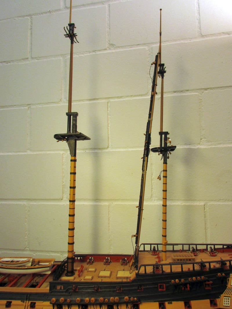
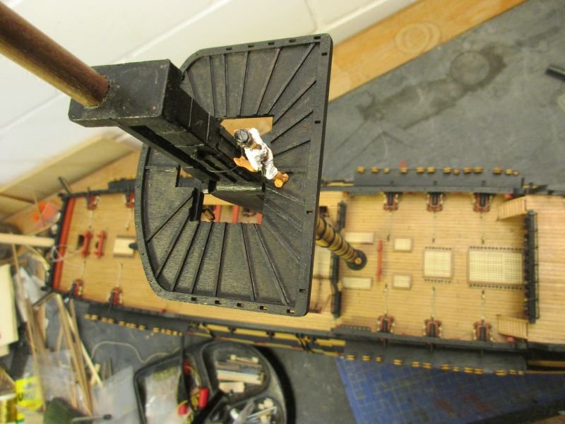
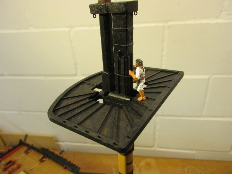
Main Mast It was built similar to the mizzen with the same small changes to topmast- and topgallant mast-feet. I've got the impression that the width of one mast top and the foot of the next upper mast should be the same, in order to fit both cleanly between the trestletrees. So again I had to double up the mast feet. The upper crosstrees are rather delicate parts and I successfully broke a couple of ends off before strengthening them with some epoxy glue. Perhaps it would be better to provide them as photo etched metal parts. Also installing the rack with the boarding pikes was some fiddling work. Finally I had to drill out the holes of the metal rings to fit the pikes properly. Details of the main top without platform yet. The topmast even has a correct octagonal (instead of round) lower end. Of course nobody will ever notice it on the finished model. the nearly finished main top... ...is quite impressively high above the deck. topmast top foot with boarding pikes the masts are only provisionally stepped
- 366 replies
-
- 10
-
-
- bellerophon
- victory models
- (and 2 more)
-
Great progress despite all that plagues. I like your supports for the foot ropes. Ehm.. I hate to be the bearer of unfortunate news but there should be at least one more after the locusts - depending on if you are looking for Armageddon(1) or just want to leave Egypt(4). Let's hope it's not a plague of woodworms. Take care Peter
- 421 replies
-
- 1
-
-
- caldercraft
- granado
- (and 1 more)
-
Hi Martin Yes, I do hope to cover all sorts of mistakes with rigging and sails - and hope to make no new ones there... And you are of course right with the x. The c doesn't make any sense in any language including mathematics. Despite the boatyard being still under construction I hope you feel already a bit at home at your new location. It's probably easier to relocate far away but still in the US than moving the same distance over here - I would have to start living in Casablanca or Moscow to travel as many miles as you and this would be a completely different world. Cheers Peter
- 366 replies
-
- 1
-
-
- bellerophon
- victory models
- (and 2 more)
-
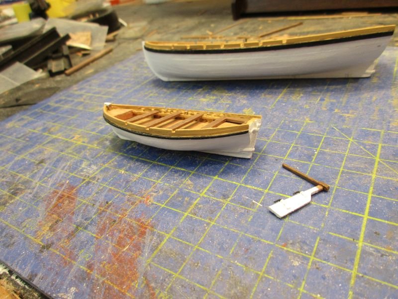
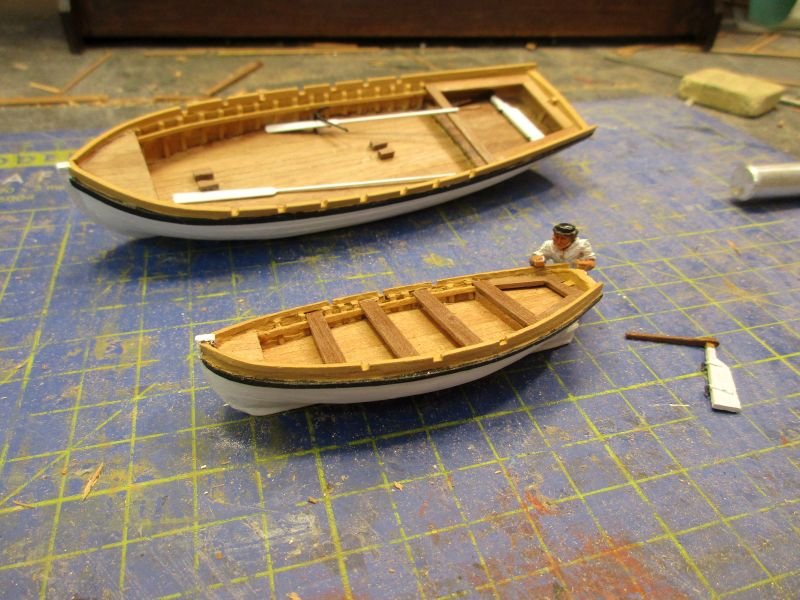
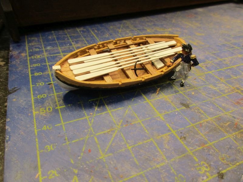
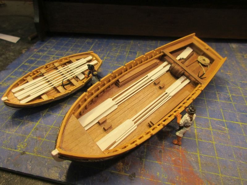
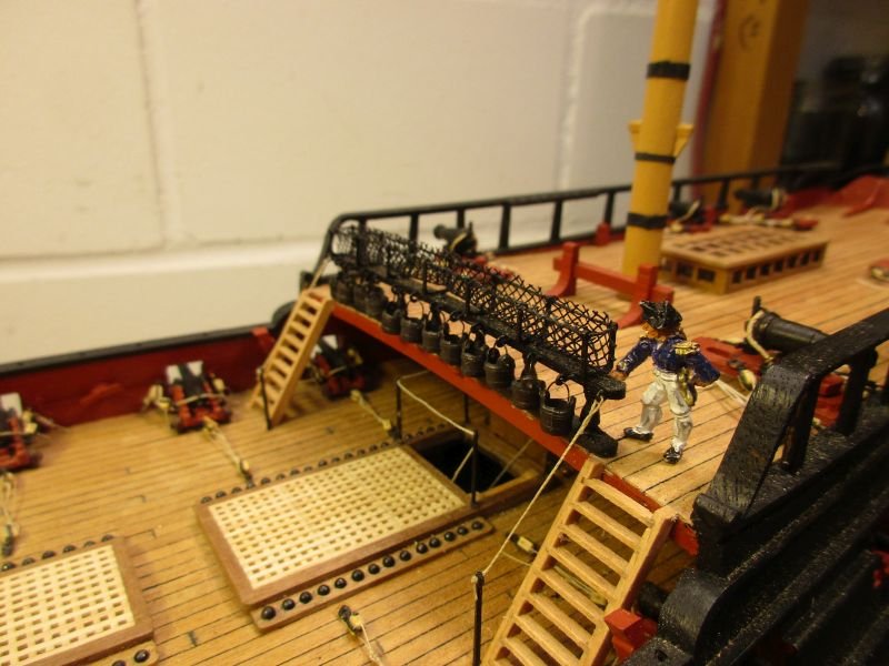
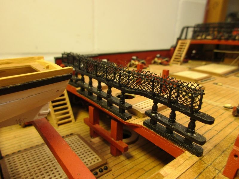
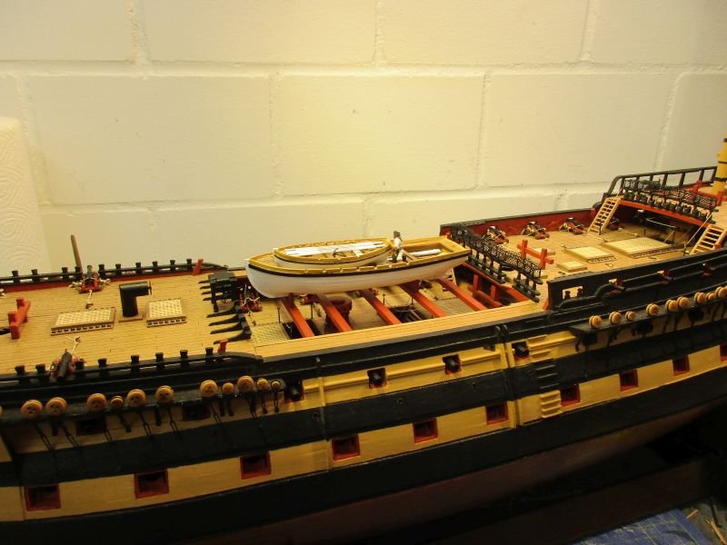
18 foot cutter One special feature - and probable inaccuracy - which was disturbing me with the launch made even more problems with this small cutter: The false floor is too high above the keel. With the 1mm thick floorboards the launch's floor is quite high up. With the cutter that problem is severely aggravated. To gain some space below the thwarts they were placed as high up as possible. I also used 0,5 mm thick deck planks, cut to a width of 2mm to plank the floor which gained me another half mm (I was really desperately looking for some space). Even so the cutter looks somehow flattened. By filling much of it with equipment I hope to mask the missing depth. For the wales and the cappings of the sides I took only 1x1mm strips instead of 2x1. That way the proportions seemed more harmonious for such a small boat. The cutter was placed in the launch and both boats equipped with the kit's oars, boathooks and grapnels. Additionally both got a rudder with a tiller and also the removed thwarts and a water barrel were placed within the launch. While working on the boat also finished the poop and quarterdeck barricades with hammock nettings and the sand buckets. the small cutter with its rudder the skipper checks the completeness of the equipment the launch with equipment poop deck barricade quarter deck barricade (I see that the top of the hammock nettings need some reworking.) the launch on the beams an overview of the work done in this chapter
- 366 replies
-
- 13
-
-
- bellerophon
- victory models
- (and 2 more)
-
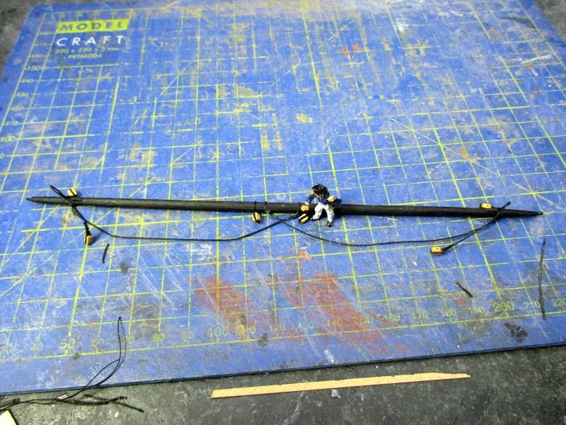
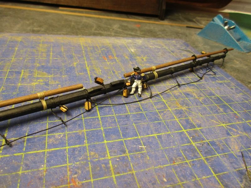
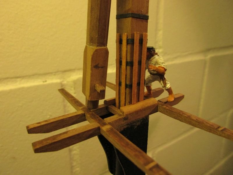
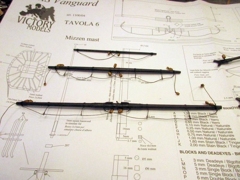
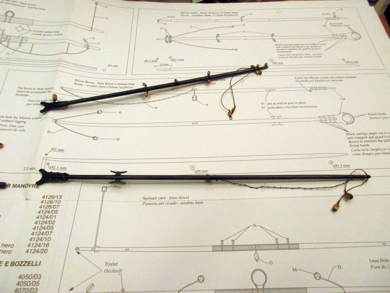
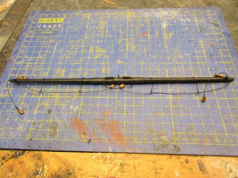
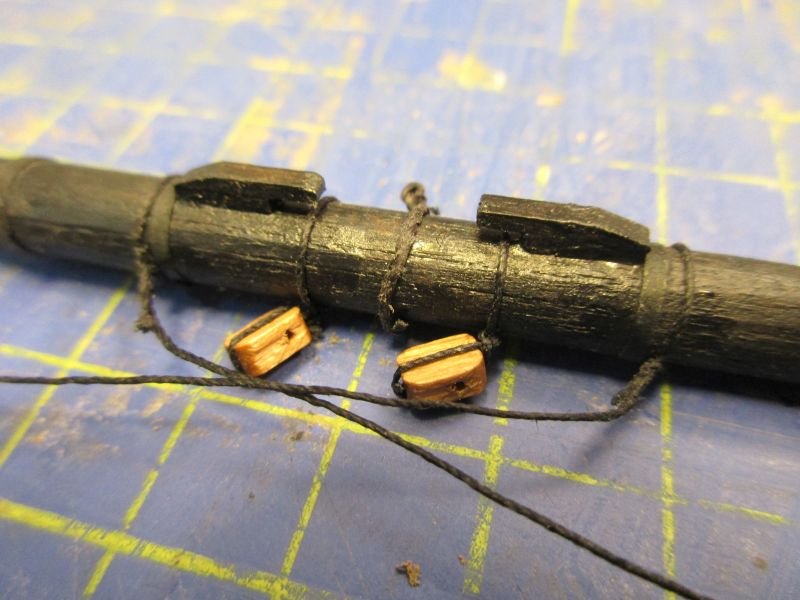
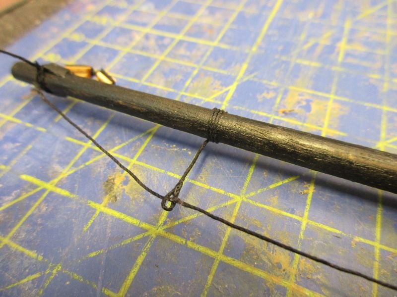
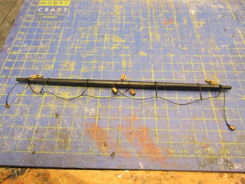
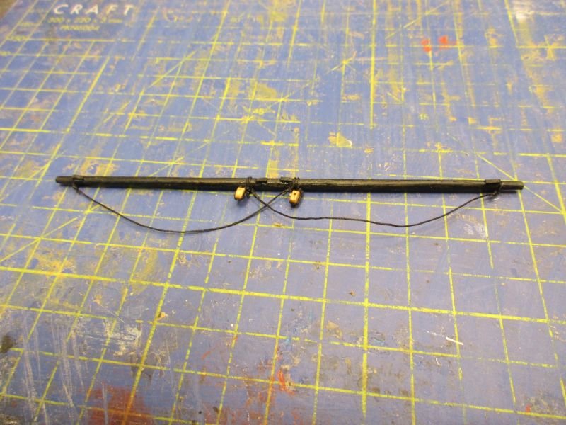
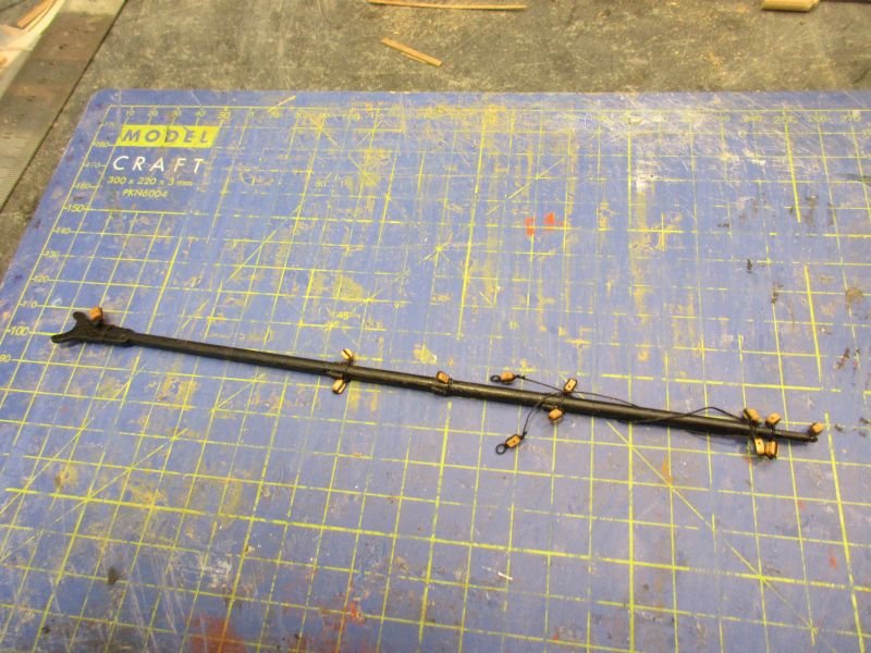
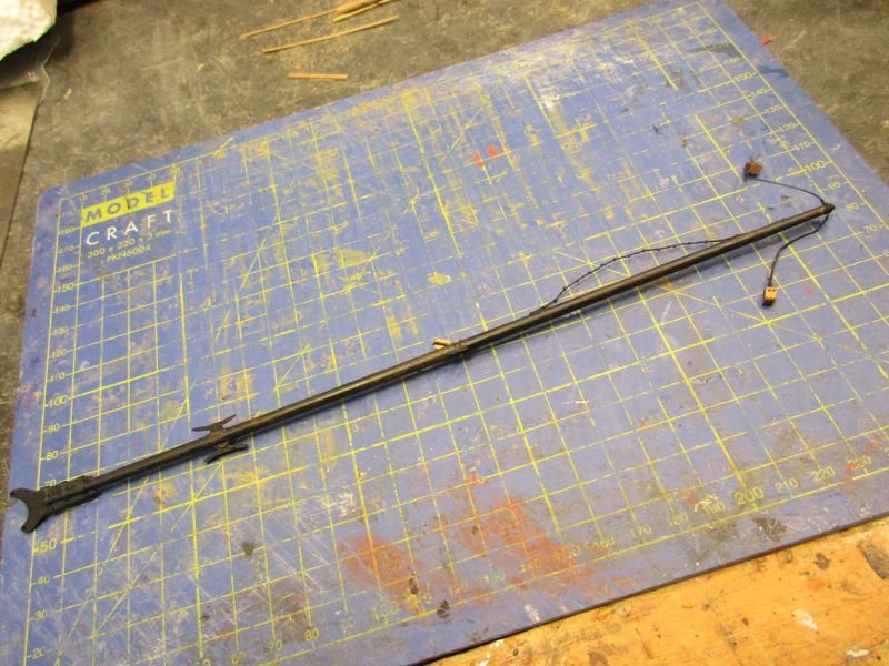
Surprisingly (but I should've known by now) the making of the 3 yards, boom and gaff was more time demanding than the mast itself. I did deviate from the kit instructions a few times, mostly when making the crossjack. First of all making the crossjack with a 8mm dowel was grossly out of proportion. I tock a 6mm one. Making the centre part 16 squared turned out to be rather difficult. Finally I made 16 battens with a cross section of 0,5x1,1mm from leftover deck planks and glued them on. Battens were usually held with iron rings. Those were simulated with stripes of cartridge paper. After all that work the centre section looked more round than hexadecagonal. (I'm not sure if that word really exists in English - I'll have to ask Sheldon Cooper or another authority on complicated words.) The spritsail yard, which is even smaller and also should be 16 squared in the centre, will probably have to be content with a round centre. Another change I made, was to replace all stirrups for the footropes by 0,5mm black thread. A eye splice was simulated at the end by threading the rope back through itself twice and hardening that small sling with glue to keep it stable. The upper end was glued onto the yard with three round turns. This looks less orderly than the usual etched metal stirrups on models but I like it and think it's a bit closer to the prototype. The rest of the work was done according to plans and instructions except that I left off those strange 4 battens on the topsail yard. If ever it should have 8 and only when the yard is made from 2 pieces. Mine is one straight piece of wood with the usual octagonal centre part. the 3 yards boom and gaff crossjack centre part of crossjack- supposed to be 16-sided stirrup topsail yard topgallant yard boom gaff
- 366 replies
-
- 2
-
-
- bellerophon
- victory models
- (and 2 more)
-
Hi Martin When checking on CT, I noticed that you will not get completely rid of the cows but you will have some decent vineyards nearby. Being in a nice rural landscape but only 2 hours from NY and BOS looks just great. I wish you save travel and a very happy landing at your new home. Peter
- 467 replies
-
- 1
-
-
- fly
- victory models
- (and 1 more)
