HOLIDAY DONATION DRIVE - SUPPORT MSW - DO YOUR PART TO KEEP THIS GREAT FORUM GOING! (Only 51 donations so far out of 49,000 members - C'mon guys!)
×


captainbob
-
Posts
3,498 -
Joined
-
Last visited
Content Type
Profiles
Forums
Gallery
Events
Everything posted by captainbob
-
You're moving right along. At this rate you'll have it finished by new years. Bob
-
Michael, I like the last drawing (#18). Since the peak of the gaff is farther back than on the Marconi, you may have to move the mast forward to keep the centers aligned. Bob
-
Don't be fooled. What you see in the pictures are the pieces of wood that have been tortured into shape. It is rare that a piece fits perfectly the first time. Bob
-
I like the idea of laminated frames. Fine start. Bob
-
New mini-mill... CNC and impressive
captainbob replied to mtaylor's topic in Modeling tools and Workshop Equipment
$4.000 and it doesn't even change it's own tools. I'll wait for the up-grade. lol Bob -
The number of boilers had to do with the size of the boat. The Shawnee at 100 feet long had only two boilers, where as the Sultana was 260 feet long and had four. The Bertrand was 161 feet long. On the other hand a lot of the riverboat builders installed salvaged boilers, engines and pumps. So nothing was absolutely defined. Bob
-
What a great thread this is. Being a riverboat buff myself I'm really enjoying it. My first model so long ago was the Shawnee, a pool boat working the locks at Pittsburg. From what I have learned here I may have to rebuild her. Bob
-
Shaping up nicely. All those little things that need to be done before the decks and seating go in. Bob
- 258 replies
-
- 4
-

-
- buzzards bay
- herreshoff
- (and 1 more)
-
As everyone has said your metal work is beautiful. But the mounting of the metal parts on the wood is also fantastic. Just like the real boat. Bob
-
We are here waiting for you. As Michael says, "You know you want to." Bob
- 258 replies
-
- 4
-
-
- buzzards bay
- herreshoff
- (and 1 more)
-
She's coming along nicely. You said, "I make my straps from mild steel wire that I run though a bead roller to flatten it out." I've been looking for model sized roller to flatten wire. What one are you using? Bob
- 208 replies
-
- 2
-
-
- john cudahy
- finished
- (and 1 more)
-
Thanks. I'll have to fine the resin based paint. Is that the Mr.Base White 1000 you mentioned in your build? Bob
- 348 replies
-
- 5
-
-
- pequot
- cable ship
- (and 1 more)
-
Popeye, it's an aluminum foil tape used for ductwork. It's .005 thick and has a waxed paper backing. I usually use acrylic paint so I dabbed some on a scrap of tape and let it dry two days. The paint came off easily with my fingernail. Bob
- 348 replies
-
- 4
-
-
- pequot
- cable ship
- (and 1 more)
-
Thanks to all oh you for your good and encouraging words. I need to paint the bulwarks but I'm afraid to paint too soon because I know the foil does not take pain well. Bob
- 348 replies
-
- 7
-
-
- pequot
- cable ship
- (and 1 more)
-
She's looking great, Patrick. I'd have to do four or five mockups just to come close. Bob
-
You're doing a beautiful job. I read in Alan Bate's book that the thickness of the walls got thinner on each higher deck so that on some boats the pilot house walls were only 1/4" thick. Bob
-
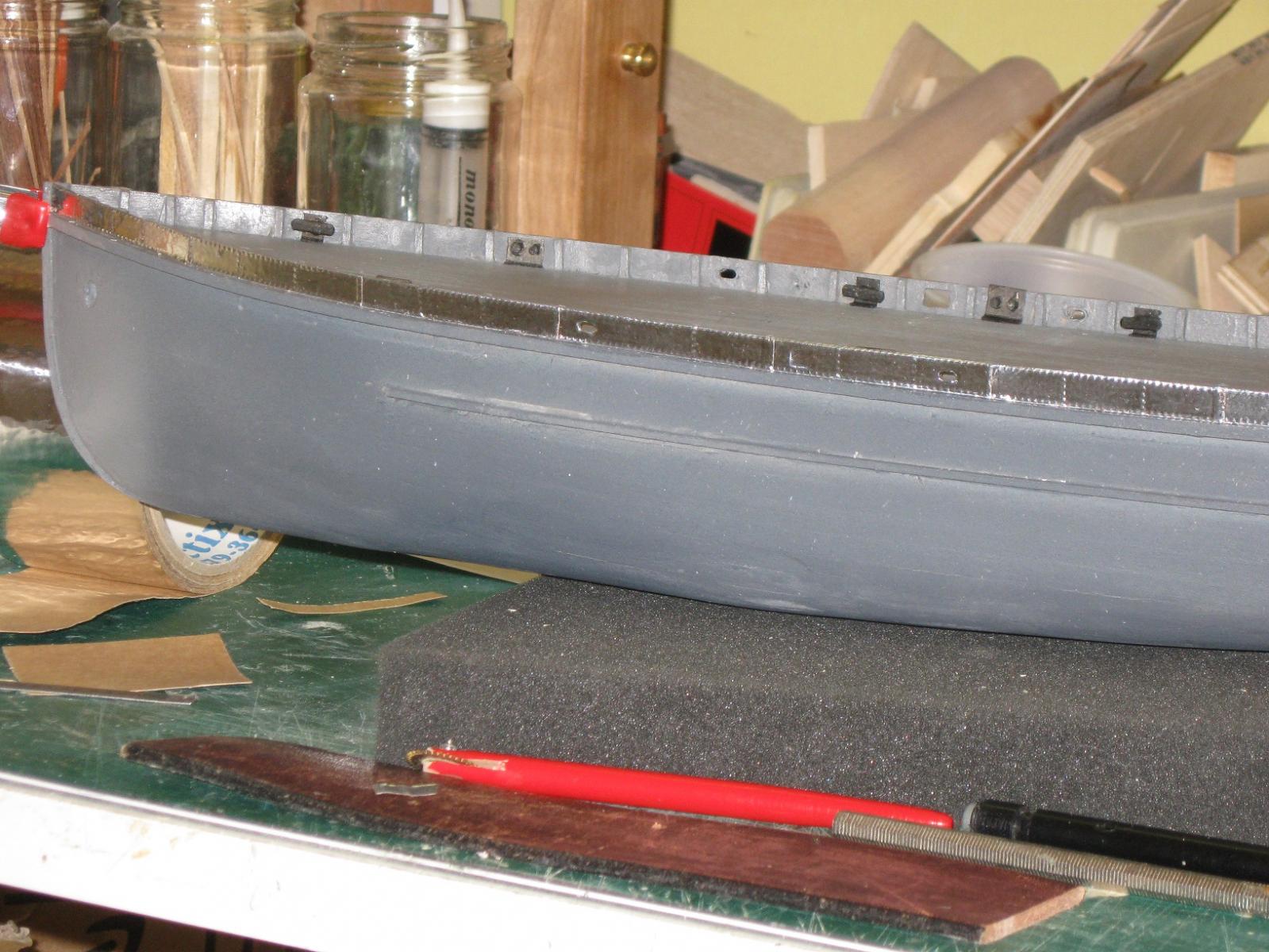
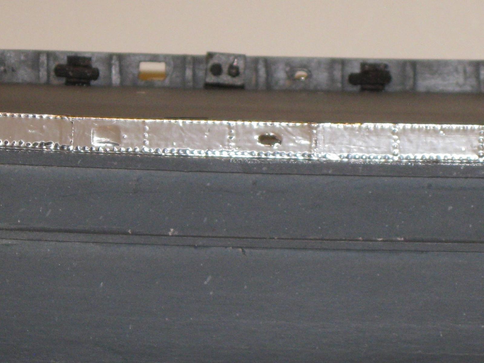
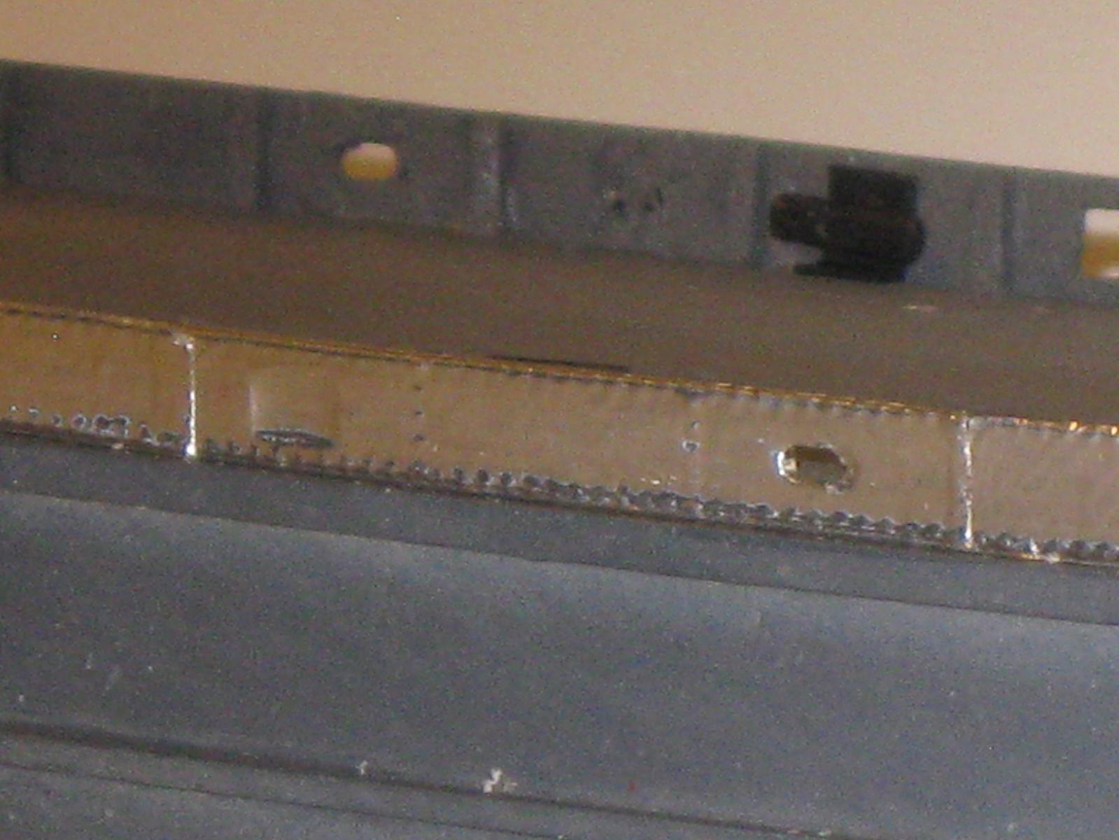
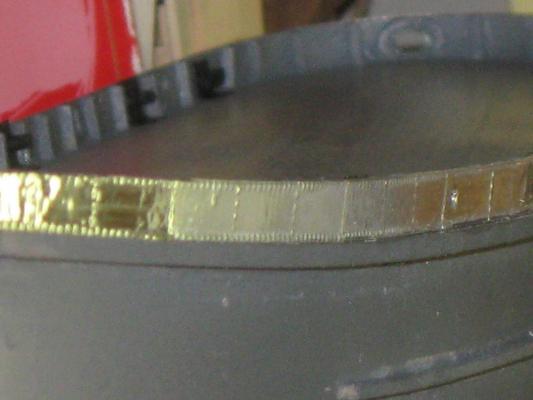
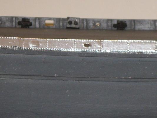
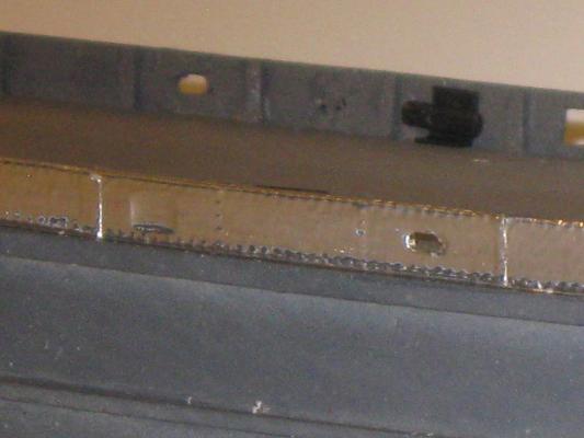
As I said before, the hull was welded but the bulwarks were riveted. I was going to show some welded seams on the hull but realized that at this scale the welds would not be seen. On the other hand, thanks to Nils (Mirabell61), I am showing the rivets. Bob You can see here how the cleats and Bollards are mounted. The rest show the riveting of the bulwarks. They and the hull will be painted black which was standard during WWII.

- 348 replies
-
- 17
-
-
- pequot
- cable ship
- (and 1 more)
-
Thanks, Popeye. I'm learning a lot on this build. So I'm not surprised you are, "interested in seeing how you do the metal hull look" I am too. Bob
- 348 replies
-
- 3
-
-
- pequot
- cable ship
- (and 1 more)
-
Reading Boat Drawings
captainbob replied to Julie Mo's topic in CAD and 3D Modelling/Drafting Plans with Software
In that case, I'm glad you found us. There are a lot of good books on boat design. The one I bought first, many years ago, and still refer to is, "Skeen's Elements of Yacht Design" by Kinney. Boat design is very challenging, but it is also a lot of fun. Bob -
Reading Boat Drawings
captainbob replied to Julie Mo's topic in CAD and 3D Modelling/Drafting Plans with Software
Frequently I find that although the height (draft) of the sections match the height of the profile, the width (beam) of the sections do not match the plan view. In this case you need to find the proper ratio of LOA to beam to draft. Then you know which to change. Sometimes the keel point on some sections do not meat the keel in profile. I measure from the base line to the keel point on the sections and transfer that dimension to the station lines in the profile. Draw a line through these lines. If the new line is not fair you know it is wrong and the sections need to be changed. If both lines are good you need to do more research to determine which is correct. When a designer starts a new boat, the ratio of LOA to beam is set. If it is a racing boat, as you are drawing, it will be narrow for the length. If it is a pleasure boat it may be fat. The grid lines are laid down. He then draws the keel and shear in the profile, the deck line in the plan, and the widest section. He makes sure the points on all the lines as the cross the grid lines match. This is done for every curved line that is drawn. This goes on and on until the plans are finished. But mainly the designer wants every curved line to be smooth and fair. The main tool of the drafting board designer is the eraser. All this being said, if you find only one or two lines that do not fit with the rest, change it, by eye, to be a smooth fit with all the rest. That's my lesson for today. lol. Bob -
Reading Boat Drawings
captainbob replied to Julie Mo's topic in CAD and 3D Modelling/Drafting Plans with Software
I find it rare to find accurate lines drawings. (If you have offsets they are usually better.) That's why I redraw them and make the necessary corrections. Bob