-
Posts
6,419 -
Joined
-
Last visited
Content Type
Profiles
Forums
Gallery
Events
Posts posted by wefalck
-
-
-
-
-
I beiieve artisanal pen-makers use such duplicators to produce small series of identical pens.
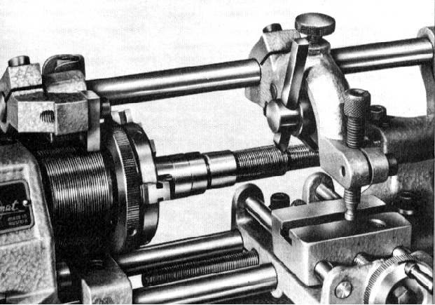
I don't know the article referred to, but there used to be a thread-'chasing' system using followers for the Unimat lathes that probably could be converted into a duplicator.

From http://www.lathes.co.uk/unimat/page2.html
- Landlubber Mike and mtaylor
-
 2
2
-
A nice piece of engineering, Pat ! It works on a similar principle as the cone-turning devices that used to be available for many quality engineering lathes.
I would agree that for columns and such things with curved surfaces it would be a good implement. If one creates a reference face to set the tool against, there is also the possibility to finish off sharp corners etc. using the cross-slide, or doing it the other way around, depending on the part.
-
Normally, a 'duplicator' only works properly, when you can disconnect the cross-slide feed-screw and pull it against the work/template with a weight on a string. Cutting sharp corners/edges (e.g. bands on canon) with a duplicator is difficult to impossible, as the tracer on the template has to have a slightly rounded nose in order follow the template and you would need to work with a pointed tool, rather than a side tool. The whole arrangement also has to be very rigid and without any backlash on the x-feedscrew.
Personally, I would not bother with duplicators, but rather make myself a sketch of the object with a precise 'turning schedule'. This means that you decide on a zero point from which to take measurement in both, x- and y-direction. You write down the various carriage movements required to turn up to particular points of your object. You will also have to think about a strategy in order to minimise carriage movements and to support thin parts - for instance, very thin parts with various diameters are not reduced to the major diameter in the first machining step, but you work on the diameters from the tailstock end towards the spindle in order to preserve as much 'meat' as long as possible in order to keep your part rigid.
You may need several set-ups to finish parts. For canon, for instance, you may need to off-set the top-slide for taper turning at some stage. Therefore, you decide on the reference surface (the zero point from above), against which you can zero your handwheels after changing the set-up.
I am usually working with a small tool that is cut like a grooving tool, i.e. it has a cutting edge left and right, so that I do not need to change tools, when turning up to sharp corners, say the left- and the righ-hand side for a band on a canon. I know the exact width of the tool and consider this in the measurements for my 'turning-schedule'.
This sounds complicated, but in fact is only structured working. It is much more precise than any duplicator on the amateur market. It is probably also faster, as you do not need to roughen out the part first in a different set-up, before you work with the duplicator.
- Bob Cleek, Canute, Landlubber Mike and 1 other
-
 4
4
-
-
This is off-topic, of course: I spent the last 25+ years helping governments and intergovernment organisations to sort out such mining legacies and to prevent them in the future ...
Back to the shipping lane dredges (which can be also environmentally problematic ...)
- hexnut, thibaultron, Canute and 2 others
-
 5
5
-
I like the high-tech roller ..,
- Keith Black, druxey and mtaylor
-
 3
3
-
As a geologist and environmental scientist, I am well aware of them. There is a sort of reality TV series on Discovery Channel on artisanal mining operations with such dredges. It makes me shudder, when I see the environmental havvoc they are causing ... 🤯
- FriedClams, hexnut, Canute and 4 others
-
 7
7
-
I have been collecting plans for dredgers for many years. I was particularly interestedin the chain-bucket dredgers, as there would be lots of visible mechanical parts to make on the lathe and mill.
The subject dredger is rather curious in the sense that the suction/cutting head could only move up and down. Normally, there would be a sort of ball-joint that would allow the head to swing in arc. Here the whole barge is pivotted on the ‚leg‘ in the rear and swung around. I suppose it would be moored off the business end and pulled to the left and right and forward too. However, I don’t see the usual winches.
will keep an eye on the progress.
- mtaylor, hexnut, FriedClams and 2 others
-
 5
5
-
Missed the start of another ‚Baron‘ ... difficult to keep up with the pace. 😉
Here are pictures of a couple of bragozzi in the Museo Storico Navale in Venice:
http://www.maritima-et-mechanika.org/maritime/venezia/museonavalevenezia-3.html
- mtaylor, FriedClams and druxey
-
 3
3
-
-
-
On 9/17/2019 at 6:53 AM, Bob Cleek said:
Actually, what we really need is some GMO (Genetically Modified Organism) boxwood, modified to grow ten times as fast and in the worst of conditions.
If wood grows fast, it means low density - just a question of metabolism and thermodynamics, regardless of species ...
- druxey, Bob Cleek, paulsutcliffe and 4 others
-
 7
7
-
Imagna, I am not at the painting stage yet. I tend to complete most of the parts, before painting anything in order not to damage any painting while fitting and handling parts.
For painting, I use high-quality acrylics readily diluted for air-brushing. Apart from ensuring that there is no grease on the surfaces, e.g. from one's hands, by wiping with aceton (if this can be done safely - not on parts cemented together with lacquer, obviously) I do not make any special surface preparations. Acrylics usually stick very well to the surfaces of the materials I use, when air-brushed.
Once painted, the parts are handled as little as possible to avoid any damage to the paint coat and not to leave finger prints that may alter the sheen (if matte paint is used).
-
Thanks all.
Well, I just put the ladder in for the photograph - have to pay attention not to mess things up, when the pieces finally come together after painting.
- paulsutcliffe and mtaylor
-
 2
2
-
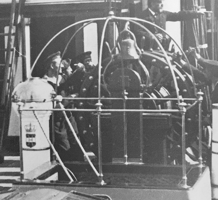
After many trials and tribulations I completed the awnings over the hatch that leads down into the the deckshouse. Such hatches were protected by railings made from polished brass tubes with connectors cast in brass. The railings had sockets into which arched awning stanchions could be fitted. The hole arrangement could be dismantled in order to be able to cover the hatches in very bad weather. The old photograph shows a similar arrangement on an austro-hungarian warship of the same period. The contemporary drawings of SMS WESPE show such quite complex hatch-cover.

Hatch and its cover on board of an austro-hungarian warship of about the same period
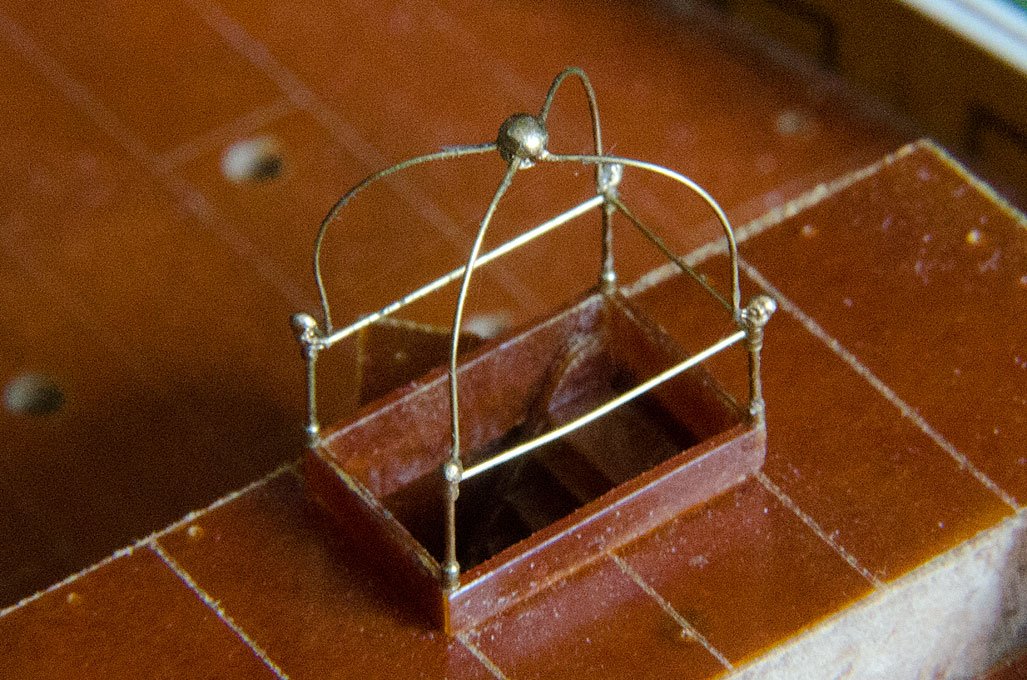
I first attempted to turn the stanchions from brass wire or small brass nails, but both materials turned out to be too soft given that they are 5 mm long with a diameter of only 0.3 mm. Even my sophisticated steadies didn’t work. In the end I had to fabricate them from 0.3 mm with 0,5 mm sections of 0.5 diameter brass tube slipped over them. The upper connectors were cross-drilled in the dividing head on my micro-mill for the 0.2 mm horizontals. I also attempted to turn 0.7 mm diameter knobs to fit onto the stanchions using a specially made cutting bit. While they turned out reasonably well, it proved impossible to fit them – I lost them faster than I could make new ones ... the knobs are simulated by tiny blobs of of white glue, painted in brass. Acceptable at normal viewing distance, but pretty awful in close-up photography.Attempts to provide the stanchions with sockets for the awning-stanchions failed and I simplified the construction by just making a wire-loop at the end, that slips over the stanchions before the knobs were made. The knob in the centre was turned and cross-drilled.
The hatch-coaming was fabricated from two layers of bakelite so that it would rest on the deck. The corners were drilled 0.3 mm for the stanchions.
Assembly proved a major challenge for my patience and took me several evenings. Luckily, SMS WESPE has only one such hatch cover. The whole structure was assembled using lacquer. It would have been better to solder it, but I wanted to keep the polished brass appearance – nothing looks more like metal, well, then metal ! Nevertheless, I have some very good metallic paint made by a Czech company (http://www.agama-color.cz/en/products/colours) that was used on the knobs.

The model representation. The hatch is 7 mm x 11 mm – close-up photographs are unforgiving
To be continued soon(?) ...
- tmj, GrandpaPhil, archjofo and 16 others
-
 19
19
-
Yes, I will try to reproduce the finish of old museum models, say with visible brass nails in the planks etc., but probably no sails. I have to deal with the somewhat rustique appearance of the planking.
Saw the UTRECHT once moored in front of the museum in Amsterdam (and have your book).
-
Yes, Artitec makes good stuff. I have had the 'statenjacht' sitting on my shelf for 10+ years. My knowledge of 18th century shipbuilding is rather limited, but I find the type aesthetically pleasing and of manageable complexity. I plan to complete it one day as a 'model of a model', rather than a realistic depiction of an actual ship.
-
On 9/5/2019 at 12:59 PM, Ab Hoving said:
I missed this post, because it was way before I joined this forum, but it really is great. You succeeded in getting the atmosphere right.
Chapeau!
Ab
Sometimes I felt (and still feel) guilty to have started from a kit, rather than from 'scratch', particularly after I had amassed probably most of the literature that is available, plus numerous pictures from preserved specimens. On the other hand, it depends on the purpose of a model, whether you want to demonstrate your craftsmanship or, whether you want to create a true to the prototype miniature as possible, based on research. I gather in the latter case, it is not so important what is 'underneath', if the appearance and details are as correct, as possible.
- pythagoras and Keith Black
-
 2
2
-
Actually, with due diligence one should have noted down all the details at the moment the deal was concluded. I would just wait a week and see, whether the item arrives.
Still, it makes me wonder, why someone sells a (new?) MF70 at 45US$, while the normal price is ten times that. Looks a bit suspicious.
-
Going to look 'ship-shape Bristol-fashion' in the words of Dana ...
- mtaylor, Keith Black, KeithAug and 1 other
-
 4
4
-
As a frequent user of ebay, I don't quite understand the problem. Did you get your mill or not ? The seller should have your address, so he can mail the mill, once he has received your money.
Personally, these days I avoid any other method of payment, but PayPal. Even though, it does not fully protect you or the seller.
There is a glitch, however, in the ebay-system: there is no formal way for the buyer to acknowledge the receipt of an item in a way other by leaving feedback. I recently had the situation that I bought an item, paid for it, the item was marked as 'shipped' and then the seller cancelled his account. The situation was aggravated by the fact that the seller was actually not located in Germany (as stated in his ebay account), but in one of the Baltic states. Hence, I had two uneasy weeks (I expected the parcel to arrive from Germany in France in two to three days, as usual), but finally the item arrived. There was no way to check on the seller, as he had closed his account. Ebay should not permit to close accounts, until the last buyer has confirmed the receipt of the item ...


Pin vice recommendations?
in Modeling tools and Workshop Equipment
Posted · Edited by wefalck
The Starret ones are toolmaker pin-vices, meant to hold reamers or files and such things. Eclipse for instance would be European product of comparable quality.
The pin-vices or needle-holders I showed originate in biology and horology respectively, I believe. I like the slender brass ones for working in tight spaces, such as rigging. You are less likely to get hooked with the tightening screw. Also, the pencil-size diameter makes for comfortable handling.
For bigger jobs I also have toolmaker-style ones.