


wefalck
-
Posts
6,664 -
Joined
-
Last visited
Content Type
Profiles
Forums
Gallery
Events
Everything posted by wefalck
-
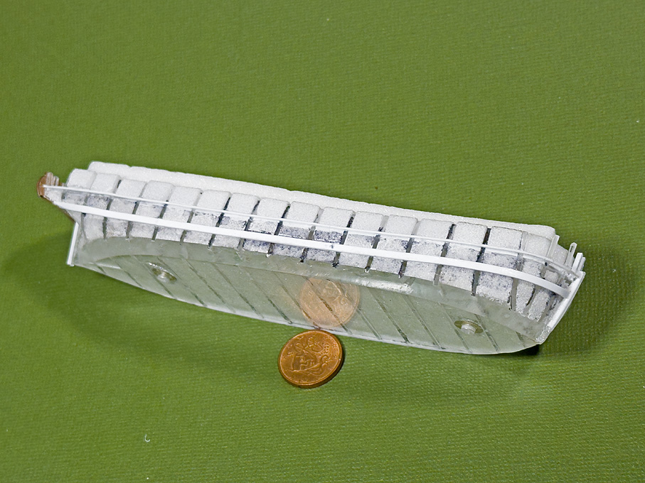
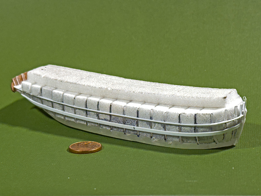
 Thanks for the 'thumbs up' ! ***************************** Installing the wales It was fortunate that the upper edge of the wale was marked in the original drawings. I had transferred this to the bulkheads and cut appropriate notches. Somehow, however, these notches turned out to be not very useful as I would have to score the whole core of the hull accordingly, which would have been messy. In the end, I ignored them, though used their upper edge as guidance for placing the wales. I have no information on their dimension, but thought that a width of 240 mm = 1.5 mm looked about right on the hull. They would have been probably composed of two thick planks. For the thickness I choose 0.75 mm, as the hull-planking will be 0.5 mm thick. Contemporary pictures and naval construction books show both options, smooth hulls, where the thicker wales are not visible and step-changes in thickness. I think smooth hulls became fashionable around the middle of the 19th century, but in the Baltic they were always lagging a bit behind, so I went for the stepped design. Perhaps this is a problem of building up the planking around a solid core, but the way how the wales run against the gilling at the stern caused me some head-scratching. The point where the upper edge of the wale touches the gilling is marked in the original drawings, but it is not clear, where the lower edge touches it. While the wales have an easy run all along the ship, at this point some twisting is needed. I had not done any planking with styrene before. It turned out to be quite simple: unlike wood, it does not have grain of course and strips can be easily bent and twisted even across the long sides. Pulling the strips around a round piece of e.g. steel causes the strips to curl and one can thus achieve a nice pre-bending without the need of much clamping force, when cementing them on. Nevertheless, the wales were attached with the recently discovered artificial nail cement, that is a mixture of light-curing acrylic cement and cyanoacrylate. It sets fast, but not so fast that no adjustment would be possible. I let it seep under the wales attached to the hull with Sellotape. Hereby I worked from the more complicated stern forward in more or less long sections, depending on the curvature. Final clean-up will be done, once the rest of the planking has gone onto the full, with the view to blend everything nicely together. To be continued ...

-
I thought this was a fairly common tactic at the time (and probably still is, using modern boat-types and propulstion systems) to attack anchored ships off-shore. Such small boats at that time wouldn't have been able to keep up with moving warships. With today's speedboats the situation is different, as the pirate-attacks in various waters show.
-
Never seen before such low bollards. I gather only a single loop/eye of wire-rope goes onto them, right?
-
So no condenser fitted? Or a boiler feedwater pre-heater? Do the steam-pipes get some insulation? I could imagine, that in winter one would get a lot of loss of pressure and condensation.
- 732 replies
-
- 6
-

-
- Lula
- sternwheeler
- (and 1 more)
-
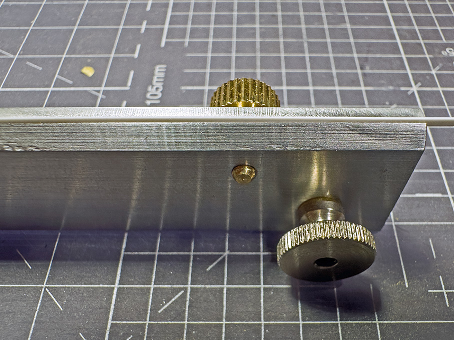
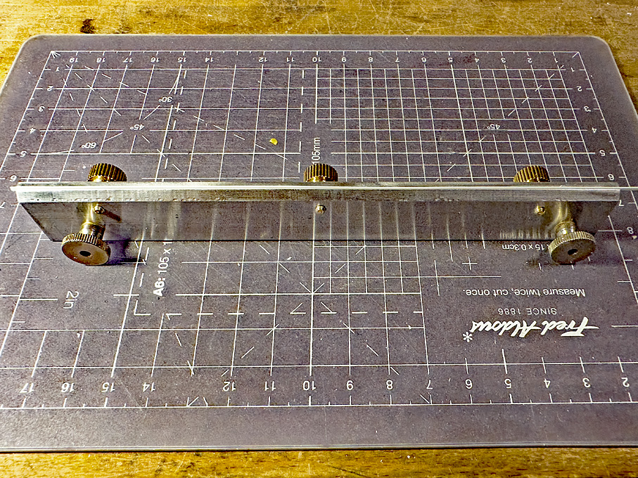
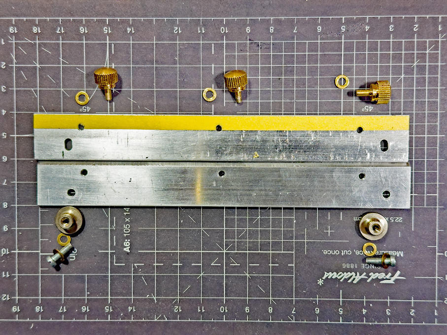
Thank you very much for the kind comments and the 'likes' ! ************************************************************* Digression 3 As the start of the planking is imminent, I had to think about a way to shape thin, narrow and long strips of styrene. A clamp is needed that can hold strips down to 1 mm width, 0.25 mm thickness and 150 mm length securely. In addition, the strips have to be held in a way that allows to slightly bevel the edges, if needed. The idea was to clamp the material between to flat metal bars of sufficient stiffness. I happened to have to matching aluminium bars of 20 mm width and 3 mm thickness that once formed part of a jig and could be repurposed. The two bars were tightly clamped together and milled flat on the top so that they abut with sharp edges. Then, one edge was bevelled to 45° to give clearance for bevelling the styrene (or wood for that matter) strips. Unfortunately, the table travel of my mill is not long enough to do the milling in one set-up and I could not clamp the whole length of the bars in the vice, which resulted in some chatter marks. Not beautiful, but still functional. The clamping action is exerted by three thumb-screws for which holes were drilled and tapped. I stuck a strip of Tamiya masking-tape at about 0.5 mm distance from the top edge in order provide a stop for very thin and narrow material. Now the clamp has to be tested in anger, to see, whether it really proves useful – not all of my home-made tools that felt like a good idea, really turned out to be that practical 🫢 Building log to be resumed soon …
-
... it also a good idea to draw onto the template the shrouds as they should be. This shows you immediately, whether you are pulling them together by accident. Leave securing the knots until you are sure that everything is adjusted to be 'ship-shape, Bristol-fashion', unless you use some organic-solvent based varnish or shellac, which can be re-dissolved, should further adjustment be needed.
-
Absolutely ! This is what the engineer would call cumulative errors. For the outhermost shrouds, I would use a 'cow-hitch' (https://en.wikipedia.org/wiki/Cow_hitch), where the loose end returns on itself. This is the same amount of work as a clove-hitch, but looks more like 'real' thing.
-
Nice clean work! How did you do the profiling of the roof, with a router, or by scraping with drawplate?
-
BR-18 Locomotive by Greg Davis - OcCre - 1/32
wefalck replied to Greg Davis's topic in Non-ship/categorised builds
Actually, nothing was welded at that time. Welding in sheet-metal construction was not common until after WW2. Contrary to what I said earlier, I think the boiler-cladding was probably screwed on in some way. It had to be removed without becoming damaged during the in-depth boiler revisions that had to take place every few years. -
BR-18 Locomotive by Greg Davis - OcCre - 1/32
wefalck replied to Greg Davis's topic in Non-ship/categorised builds
I did not examine the photographs of the original, but wondered whether they actually used such prominent 'rivets' on the boiler-cladding (this is thin layer of sheet metal over an insulating layer, but I don't know what was used on these locomotives, perhaps asbestos sheet). They took great pride in their appearance then. I seem to vaguely remember from the catalogue description when Arnold Rapido produced a N-scale model back in the early 1970s that the painted surfaces where puttied and sanded down several times, then several coats of paint with sanding in between, and finally several coats of gloss varnish. That applies to the green livery, not the later black livery. So they probably would also have used sunk rivets and puttied over them. Hence, the rivets would not interfer with any 'coach-lining'. -
Nice work on replicating this 'granulation' or 'filligree' as jewelers would call it. There is also a little-known tool called a millgrain-wheel that can be used to create decorative beaded wire. It's kind of a concave punch-wheel and sold for different bead-sizes and spacings.
-
You could make yourself a little jig for making the shackles: just to pins in a piece of wood around which you wind the wire for the shackels. Make sure that you pinch the eyes in a way the connection between them is right in the middle, i.e. are symmetrical to the loop of the shackle. Another method that works for really small shackles is to flatten the wire at both ends a bit with a punch or flat pliers, then drill the holes for the bolt and finally file the ends round. These guys most probably did not have much access to sophisticated hardware, but then as they found turnbuckles, they may have also found shackles. The turnbuckles, however, do not seem to the marine version.
- 312 replies
-
- 7
-
-
- Chile
- Latin America
- (and 6 more)
-
Pin vise recommendations
wefalck replied to kgstakes's topic in Modeling tools and Workshop Equipment
On the original question: the question is always what one wants to do with a tool. One may need different sizes and different types for different jobs. I have a whole range of sizes and types. There is also a short version used by tool-makers to hold small files or reamers, which I find quite useful for certain applications. I got them in a second-hand lot by chance, but one could also shorten commercial ones, of course. For drilling, there are also miniature archimedean drills. I got one from a watchmaking supplier nearly 40 years ago that virtually clamps down to zero. The advantage is that they have free-spinning head, which allows you to put pressure on the drill, while moving the dolly up and down. There are also spring-loaded 'single-action' models. Don't go for the cheap small archimedean drills that have appeared on ebay & Co. a few years ago, buy quality. -
Possible Planking Clamp?
wefalck replied to Thunder's topic in Modeling tools and Workshop Equipment
The idea is to pull up the edges of grown-in toe-nails. Bought one of thosen years ago to be used indeed as gear-puller and for similar tasks. -
I must admit that I don't know next to nothing about the shipping around the Pacific coast of the USA. I am always amazed that at the beginning of the 20th wood was still used as constructional material for quite substantial steam-ships, but then wood must have been a comparatively abundant resource in that part of the world. Why did you settle on the odd scale of 1/71 (if I understood correctly) and did not go for the common scale of 1/72 ?
-
A marine dictionary, such as Paasch's 'From Keel to Truck', that in it's 4th edition of 1908 not only covered English, French and German, but also Spanish and Italian, might help sorting out questionable machine translations. I think it is available as PDF.
- 139 replies
-
- 2
-
-

-
- ancre
- Bateau de Lanveoc
- (and 2 more)
-
BR-18 Locomotive by Greg Davis - OcCre - 1/32
wefalck replied to Greg Davis's topic in Non-ship/categorised builds
Yep, but Bavarian locomotives were not painted in 'any' colour. The standard livery was green before the state railways were unified into a national railway in 1925. The 'livery' of the 'Reichsbahn' was black with red frames, wheels and inlays in works. At some stage the S2/6 also was painted in yellow-ochre for an exhibition or something. I think the lining then was red, but one would need to check. -
Same for me ... posted too early or too late. I think there is a lot of tradition involved in Europe. You N-Americans seem to have been much less inhibited by traditions. Push-barges didn't came into use on European rivers (mainly the Rhine) until the 1970s or so. Before it was side-wheel or propeller tugs with a tow of a maximum of four to six dumb barges. On Eastern European rivers, that were less well-regulated, wheels seem to have persisted longer, though quite a bit of research had been going on to improve screw populsion in shallow waters through putting the screws into tunnels. One river on which sternwheels have been used for quite some time was the Rhone, but not for tugs, but for fast packets. No idea what reasons where, why they kept for so much longer 'towing' than pushing.
- 732 replies
-
- 5
-
-
- Lula
- sternwheeler
- (and 1 more)
-
I was thinking of parallel towing in harbours etc. However, it seems that in N-America the rivers tend to be more violent than even the unregulated rivers here in Europe.
- 732 replies
-
- 6
-
-
- Lula
- sternwheeler
- (and 1 more)
-
scissors, shears, cutters for rigging
wefalck replied to palmerit's topic in Modeling tools and Workshop Equipment
I wouldn't really know, as the description does not mention the solvent. I know what kind of varnish is used for, but wouldn't know the viscosity or drying time of this particular product. Another option used by some people here would be a shellac solution. The solvent is alcohol, which dries fast, but not as fast as other types of organic solvents. The advantage is that from shellac flakes and alcohol you can mix up solutions to any viscosity you find useful. -
scissors, shears, cutters for rigging
wefalck replied to palmerit's topic in Modeling tools and Workshop Equipment
Objectively, there is no reason not to use it in the house. We use only tiny quantities and would not keep the container open for long times. Of course, if I were to treat a silver chandelier or something like that, I would like to have good ventilation ... However, the law is the law. You would need to find a fast-drying varnish based on an organic solvent. The point is relatively low viscosity, good penetration because of low surface tension, good wetting properties (particularly when working with man-made fibre ropes), and easy reversibility of the bond. These are all properties that do not really apply to acrylics or PVA glue. I have never used the latter two for this purpose for those reasons. -
I gather this would be a colour often referred to as 'duck egg blue'. Adding a wash of ochre could get you there or mixing it up for another coat. Adding orange possible makes it too dark. I would assume that the owner's would put on any colour they could lay their hands on (like the famous houses in the La Boca area of Buenos Aires) and that took their fancy. Black hulls with white trims has been the fashion since the middle of the 19th century. Black and white are also among the cheapest colours you can get. It was only after WW2, when synthetic pigments made it possible to have the same price for all colours.
- 312 replies
-
- 4
-
-
-
- Chile
- Latin America
- (and 6 more)
-
scissors, shears, cutters for rigging
wefalck replied to palmerit's topic in Modeling tools and Workshop Equipment
I am using so-called zapon varnish, which is fast-drying and remain a bit elastic. It is basically invisible and does not add volume to knots etc. Old-time nail-varnish, not the modern acrylic version, is/was essentially the same. The main use of zapon varnish is to coat silver- or brass-ware to prevent it from tarnishing. As the USA seems to have overtight regulations on organic solvents in some states, it may be difficult to find. Unlike white glue or acrylic varnishes, this varnish can be easily redissolved with a drop of acetone, if you need to adjust the knot. Not sure, why you want to cut close to a knot. Normally, when a rope is tied to something with a knot, there is a 'tail', the length of which depends on the situation. The only situation I can think of for cutting close would be when belaying to a pin and you want to prepare the coil separately. Another situation for making close cuts would be after splicing. Here, the varnish prevents the strands from slipping out after being cut back closely. -
Interesting feature, these push-knees. That is something rarely seen in Europe on tugs until a few decades ago. I would have thought that the driver would have been tied up alongside for manoeuvering it around and then tied up to the shore and two anchors laid out at the rear to keep it in position and to move it along for the next pile.
- 732 replies
-
- 4
-
-
- Lula
- sternwheeler
- (and 1 more)