


wefalck
-
Posts
5,565 -
Joined
-
Last visited
Content Type
Profiles
Forums
Gallery
Events
Everything posted by wefalck
-
 Ahh, that's not a 'primer' in the technical sense. In art it would be called under-paint and was indeed used by the Old Masters, say green under areas of skin to provide depth. Now I understand your point. I also use 'under-paints' or base-coats, when a model is made up of different materials to have a common starting point for the actual paint, if it is with a pigment that may not be covering very well, say red for example.
 -
Yes, acrylic primers may not adhere very well to 'non-polar' surfaces, such as metals or most plastics (with the exception of acrylics/Plexiglas/Perspex). Solvent-base primers do better here. We have over in Europe also pure acrylic-solutions, without anything added, that are supposed to be good primers for metals. I rarely prime, as it is not really needed for static models, so I don't know, wether is any advantage in those pure acrylic solutions.
-
But the primer is the thing that normally provides the 'grip'. I don't understand why you want a 'sealer' and a 'primer'. If you use the acrylics as a primer, you can go on painting on these straightaway.
-
Holding small parts for soldering
wefalck replied to BETAQDAVE's topic in Metal Work, Soldering and Metal Fittings
Learned that in my teens -
Holding small parts for soldering
wefalck replied to BETAQDAVE's topic in Metal Work, Soldering and Metal Fittings
Have to try that - have both Tamiya masking tape and a selection of soldering irons of various sizes and a small (reflow) heat gun for no-touch soldering. -
Why would you apply an acrylic 'sealant' on metal - sealing metal against what ? Normally, metal primers are there to increase the adhesion of paint to metal surfaces, for instance by slightly etching them. I can understand the use of a primer on certain plastics, if you want to continue with organic solvent-based paints, but acrylic 'sealants' are probably based on a polar solvent, such as water, which do not show very good adhesion to non-polar surfaces that most plastics have. So what are the advantages of using acrylic 'sealants' on plastics?
-
Holding small parts for soldering
wefalck replied to BETAQDAVE's topic in Metal Work, Soldering and Metal Fittings
What masking tape are you using? In the past I tried painters' masking tape but the glue on it melts and leaves some residues that are not so easy to remove. -
Wasn't meant to be a challenge, just an observation from various paintings. While in a way counter-intuitive because of the top-weight during the launching, it was probably easier to step the masts early on: you don't have to lift them that high and there fewer things to damage in the process. To lift the masts into the cabins requires some pretty tall sheerlegs as well.
-
Well, what praise can one still add ... 😲
-
One should dive into the files of the military archive of the state archive in order to see, whether any reports of the commanding officers have survived. My understanding is that the commanders had to send report to Berlin after each commission (the boats were not kept permanently in commission). Such reports still exist for instance for the Prussian gunboats of the early 1860s. With the twin-screws the boats may have been able to wiggle themselves out of the mud.
-
In my case, I would only be able to post stamp-sized pictures
-
I think the original idea was to reduce the turning circle following an attack. Torpedoboats and destroyers would approach their target at high speed, fire their torpedos and then turn away quickly to get out of the range of the artillery of their targets. The long narrow hulls would make torpedoboat very slow turners.
-
Thanks, Keith .... Well, while it would have been possible to fire gun something like 30° to either side, training the gun was not a very fast and precise. In fact, there were a number of men cranking away under the barbette, while the gun-captain could engage through some sort of reversing gear the lower carriage with this cranking sytem. In this way he could train the gun left or right with the help of a lever. However, I think the normal tactics would have been to keep the gun steady and then approach the target in a shallow arc - when the target went through the sights, the gun was fired. This would have been also the tactics for the Rendell-gunboats of the RN. In addition, the WESPE-Class was twin-screwed with two independent engines, so using the engine-room telegraphs, the boat could also be turned slowly by going forward with one engine and backward with the other, again waiting for the target passing through the sights, rather than training the whole ship onto the target. I think the reason, why Middendorf (who later went on to design the five-mast ship PREUSSEN) opted for the central pivot carriage was, that another tactical concept was to allow the ship to fall dry on the tidal flats of the German Wadden Sea and be used as a sort of detached fort, keeping the enemy out of range from the coastal towns and fortifications.
-
What kind of 'stainless' steel then and what kind of blacking?
-
One can blacken carbon steel, that's what gun-smiths and toolmakers do all the time, but per definition, you cannot blacken stainless steel (blackening after all is a metal 'stain').
-
Some 43 years ago I published and article (in German, sorry) inter alia on this subject: https://www.maritima-et-mechanika.org/maritime/tips/FALCK-SM-5-80.pdf. I cut out the sail from the silkspan (in this case the fabric) with a 2 cm margin or so and suspended it from four pins over a board. Then the paint was put on with caution. The process was repeated from the other side, once the paint was dry. Today, I am actually building up the sails from individual panels that are stuck together with varnish. It's easy to avoid any creases that you cannot iron out.
-
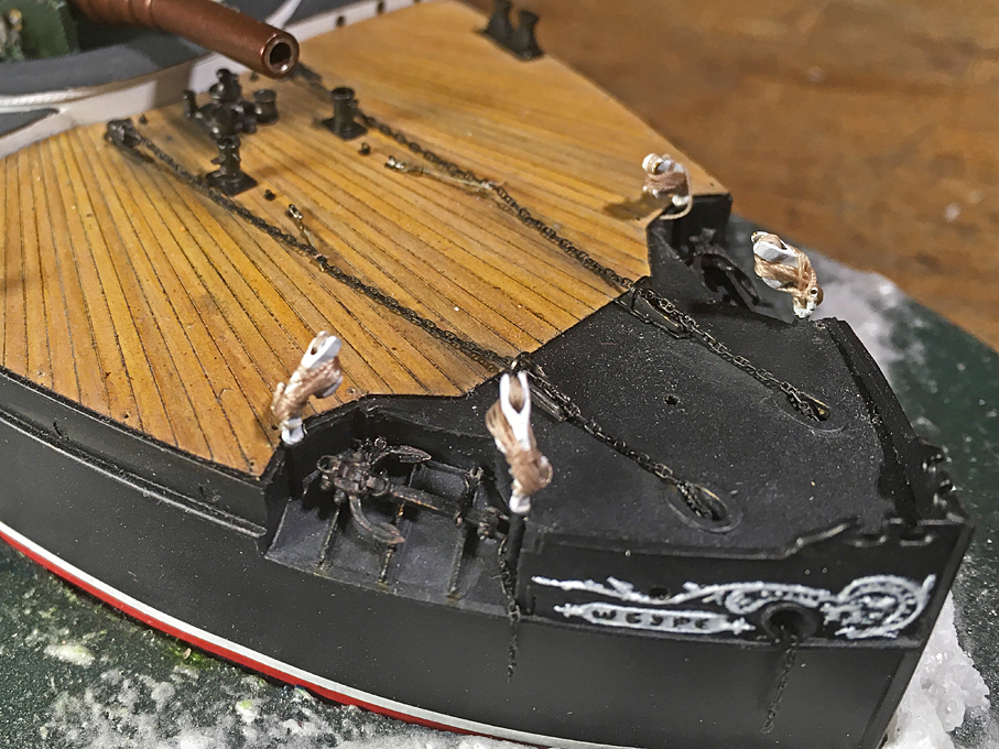
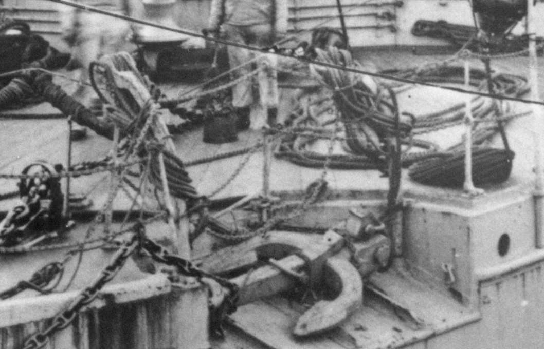
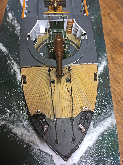
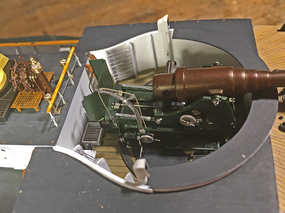
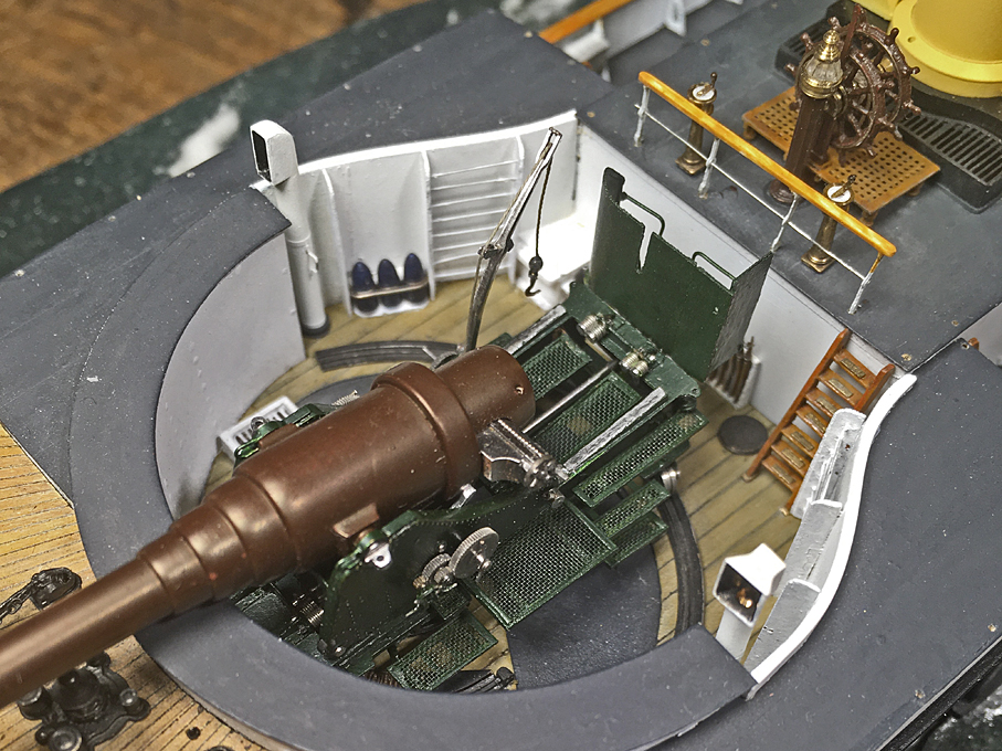
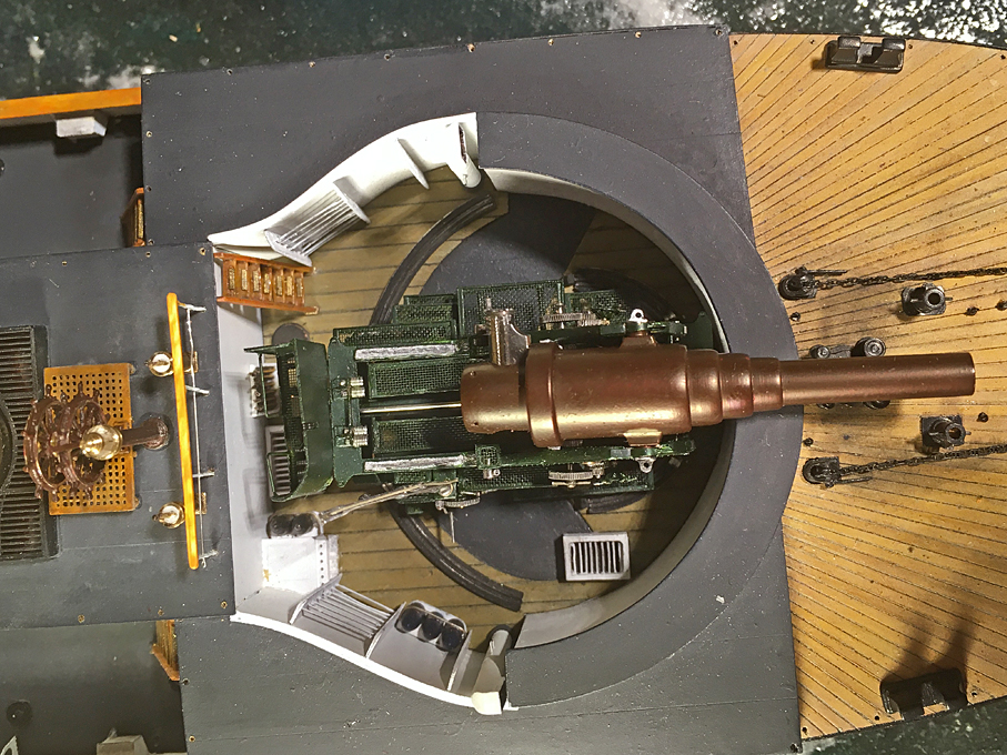
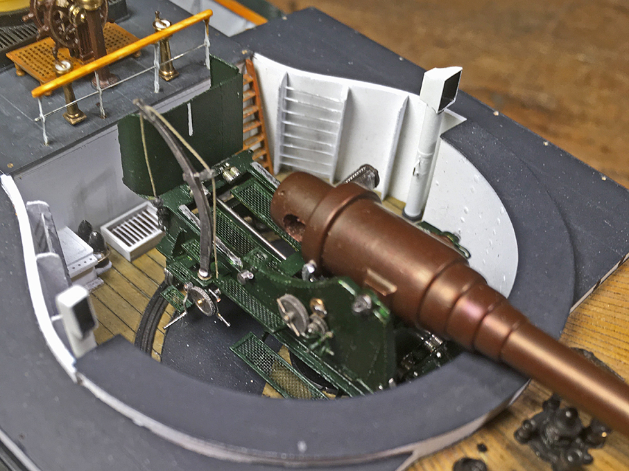
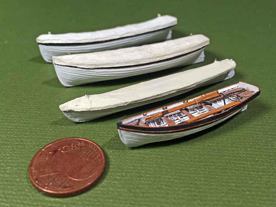
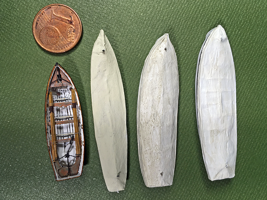
Well, the master-miniaturist speaks - Thank You ! ************************************************ Small bits and pieces Here are a couple of ‘family pictures’ that show all boats together and with a 1 €-Cent coin for size reference. The jolly-boat also got a bow- and a stern-lanyard added that I had forgot earlier. From top to down: 1st cutter, 2nd cutter, gig, and jolly-boat Now that with the boats the major ‘sub-models’ have been completed. The process of putting everything together continues. Thus, I have put the gun onto the tracks of the lower carriage. It was just glued in place – something I am not entirely happy with considering the top-weight of the barrel, but hopefully I have added enough white glue at hidden places. The original had clamps that go under the tracks, but this was difficult to reproduce at this scale. The gun in its emplacement in the barbette The two engine-room telegraphs were installed on the bridge. Engine-room telegraphs on the bridge I am not sure that these were rigged like that, as the existing photographs are either not taken from the right angle or the resolutions is not good enough for the forecastle is too messy. Anyway, two cable stoppers fashioned from ‘rope’ were attached to eyebolts (which were drawn in the plans) and provide additional security against the anchor-chain flying about on the forecastle Cable stopper to secure the anchor-chains. The four anchor cranes were completed with the tackle and temporarily installed. There would have been quite a few metres of the running part to stow securely while on sea. Judging by the photograph of S.M.S. CROCODILL below, it was slung around the cranes in a perhaps not quite so ‘ship-shape and Bristol-fashion’. Anyway, I emulated this on the model. Anchor cranes on S.M.S. CROCODILL later in her life The anchor cranes on the model Next up is the most dreaded part of the model, the installation of the various chain rails. Because of these I hesitated for a long time to tackle this project. To be continued ....
- 882 replies
-
- 20
-

-

-
Ah, these photographs are alway terrible and so true and honest to all the mistakes and imperfections one commits ☹️
-
One day I would love to see some images of your workshop
-
Back on board too! I admire your tenacy and optimism in these difficult times. Why did you opt for the somewhat odd scale of 1:45? OK, it's model railway scale, but awkward to calculate (in the head). You already made quite good progress on the hull. How long did it take you for that?
-
Looking very convincing! I wonder, why they didn't cast on a spigot right away. They could have used it for the casting process as riser or something. I don't know much about such constructions, but wondered whether there shouldn't be some sort of sleeve or a sheet of metal around the sheet-metal stove-pipes to prevent the shingles from catching fire?
-
I think your original question was about a difference of rake between masts, top-masts and topgallant-masts ? The answer is probably that there shouldn't be a difference. If there was, somehow the tops and the caps are not properly matched. However, a slight difference is not really consequential from a sailing point of view, only perhaps from an aethetic one. The actual rake was very much subject to fashion and tradition. For instance, it became fasionable to have extremely raked masts around the 1840s, but by the end of the century the became basically vertical. The tradition is that the rake increases from front to back. On the other hand, there are many vernacular craft that had extreme rakes in both directions and often on the same craft - think of certain Portuguese or Chines boats. For a given sailplan the actual rake of the mast will move its centre of gravity slightly, but taking in or setting sails probably has a more profound effect on a square-rigged ship. The situation is somewhat different on sloop-rigged yachts, which carry most of the time the fore and the main - there, changing the rake changes the tendency to turn leeward or otherwise, giving more or less pressure on the rudder/helm, and changes the turning behaviour when going through the wind.
-
Using the real wood species for a model usually does not work, because the grain patterns are too coarse. For a model some wood without visible grain is more realistic.
-
US 6” gun by RGL - FINISHED - Panzer Concepts
wefalck replied to RGL's topic in Non-ship/categorised builds
Wow, that is a lot of money to sink into a kit ... -
Wow, this is serious competition in the field of micro-machining ...
