


wefalck
-
Posts
5,568 -
Joined
-
Last visited
Content Type
Profiles
Forums
Gallery
Events
Everything posted by wefalck
-
 Does not exist. The closest is 1:60, but commercially there are only the classical flat tin-soldiers as far as I am aware. I know this, as I built a couple of models in that scale and was never able to crew them - my sculpting capabilities are not that good. Until some 25 years ago there was a Swedish company Rose Miniatures that also made 30 mm 3D-figures. Some of the 'war-gaming' figures might work, but they are nominally 25 mm. I think the figures of Perry Miniatures (https://www.perry-miniatures.com) are nominally 28 mm, which translates to 5" in a 1:54 scale - still a bit on the small side. One has to scan their range to see, whether any figures for conversion into marine civilians would be available. Personally, I am not very fond of the war-gaming figures, as for some reason they are always chubby, almost cartoon-like representations with too big hands and feet.
 -
Well, these tours de force in brass-work are never boring ! Perhaps the horizontal hinge for the fore-boom is to allow it being topped-up ? I admire the resistance of you Brits - with 10°C only my workshop would have closed already for hibernation ... 🥶 ... We whimpish continentals were brought up in heated schools and with long trousers.
-
For a ship at sea there are an awful lot more variables to consider: the constant rolling, heeling and pitching changes the aspect the sail presents to the wind, the wind itself changes direction not only in the horizontal, but also in the vertical, the wind speed constantly changes slightly, due to the ship's movement and the movement of the waves the wetted surface constantly changes, the length of the waves and hence their interaction with the ship-generated waves constantly changes, etc. etc. Some of these variables can be simulated numerically and generated randomly, but that requires a huge amount of computer-power. In principle it is easier for the water part, because water is not compressible. This is why in many cases experiments in wind-tunnels and/or wave-troughs etc. with scale-models are still needed.
-
Painting White/Pot Metal.
wefalck replied to JohnB40's topic in Painting, finishing and weathering products and techniques
As previous contributors already noted, figureheads on real ships were always painted and at some times at rather garish colours - sea-folks were not necessarily aethetically refined For wood effects I begin with a light tan (e.g. Vallejo 'wood') sprayed on. This gives a good key for the following washes applied by brush. These washes depend on the wood species I try to simulate. Colours may include other tans/beiges, burnt umber and sepia/caput mortuum. Vallejo also has mahagony in their range. The Vallejo 'wood' and 'mahagony' also come in 'transparent' versions that facilitate washes. Another useful colour is their 'transparent orange'. I use their 'model air' range a lot because I don't need to bother too much with diluting, but just put a drop onto my glass palette and further dilute with water as needed. These days I prefer acrylics over oils for this as one can work much faster. Building up layers of oil washes can take days or even weeks, as each wash has to properly oxidise ('dry') or you risk to wash it off with your next wash of heavily diluted oil-paint. Acrylics dry within in minutes and after 10 to 15 mins the latest it is safe to apply the next wash. Depending on the effect I try to achieve, I may be using round or flat hair-brushes or bristle brushes for a more streaky appearance to simulate wood-grain. 'Wood-graining' used to be a craft in itself and some artisanal painters used to specialise in it. It was popular from around the middle of the 19th century to the 1920s or so, when many metal artefacts were decorated to look like wood. Sometimes also cheap woods were made to look like more expensive ones. Today, hobbyist still use the technique and there are guidebooks for it on the DIY book market. I myself and I gather other (plastic) modellers learned from such books. -
Where can I buy this tool?
wefalck replied to EricWilliamMarshall's topic in Modeling tools and Workshop Equipment
Be aware, however, that these Archimedes-drills are actually meant for use with so-called spade-drills. Spade-drills are not fluted, but cut in both directions on account of the reciprocating action. For this reason they are also not very suitable for drilling deep holes. They are still quite popular with watchmakers, as they do not 'catch' in soft brass, unlike standard fluted drills. Watchmakers used the make them themselves, but they are also available (as the drills) from watchmakers supply houses (which is where I got mine some 30+ years ago). The sprung version pops up everywhere on ebay and I think some modellers supply houses also carry them. The large wooden version may not be very useful, as their collet is actually machined for bits that are square at the mounting end - at least the one I was given as a kid in my first tool set around 1964 is like set. In fact, I rarely used it and knowing my father's cranked hand- and electric drill considered it already then an antiquity. -
These Saxons ask complex questions Perhaps one should devonvolute them a bit: I gather you already learned that air is a compressible 'fluid', which makes things more complicated and simple static calculations may not be sufficient. A sail is a complex shape, it was not only the outside dimensions, but is curved in two dimensions. I gather there is a formula to calculate the resistance of a hemisphere in laminar flow, but here you are dealing with a surface that has one or more linear edge (where it is attached to e.g. the spar) and three other edges that follow more or less the shape of a catena - that is assuming that the wind hits the sail perpendicular to the main axis, which in fact is rarely the case. Well, I assume that there must be some some sort of engineering handbook for designers of sails for competitive sailing boats ... on the other hand I think a lot of these questions are resolved in wind-tunnel experiments or some high-end fluid dynamics modelling for compressible and turbulent fluids. Turbulence behind the sail (see Karmann) is an important aspect. The breaking strength of rope obviously depends on the material and the way how it is made. For wire-rope one may be able to calculate this from the properties of the individual wires, as these can be manufactured to specified properties. It is different for natural fibres, the strength of which is only roughly known and varies from source to source. These properties are usually determined/verified experimentally. There should be some rough estimates in late 19th/early 20th century rigging textbooks, when materials testing was developed. The third question can only be answered, when you know the exact geometry of the sail. I could imagine that for a given shape this could be answered with modern computational fluid dynamics that take into consideration both, the compressibility of the air and a highly turbulent flow (not many packages can do this, I believe). Otherwise, wind-tunnel experiments still would be the answer. However, as wind-tunnel experiments are expensive, it may be quite possible that the serious competitive yacht-designers now have computational tools that can do the above simulations. Perhaps you should look into this direction. In any case, with simple static calculations you will not get very far and you wouldn't even know, whether you are on the safe side with your results ...
-
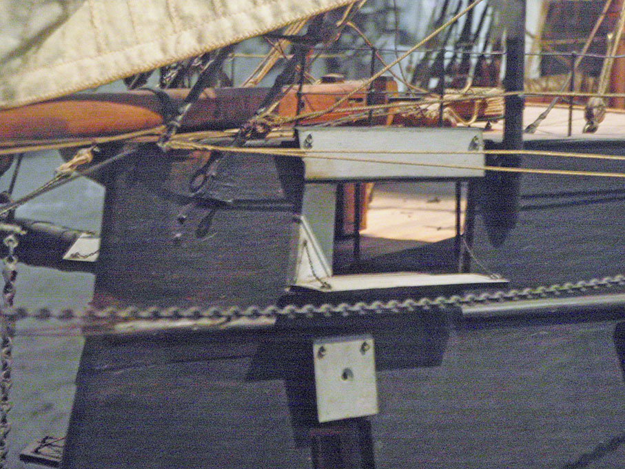
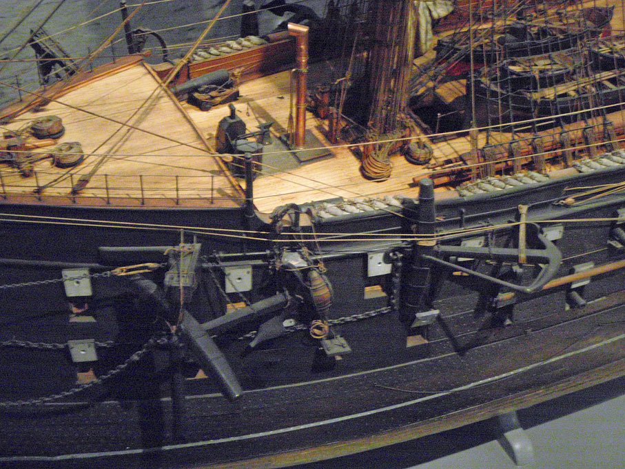
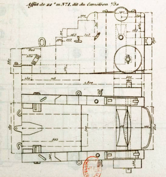
I did a bit more research on what presumably are the chasing guns, namely the 22 cm-guns. The plans from the Atlas de la Genie Maritime indicates some sort of curved low sill or threshold (seuillet) behind the chasing ports, but the model in the Musée de la Marine does not seem to show this. The deck seems to be flush: I would have assumed that somehow the sill would have served to anchor the slide-carriage. On the other hand, the model does not sport any slide carriage at all. What looks like the 22 cm-gun is lashed to the bulwark just behind the quarterdeck: The carriage does not appear to be an ordinary 2-wheeled carriage as pictured in my previous post for the 16 cm-guns. Unfortunately, my photograph is too pixalated to see clearly (even on the full-resolution image). A possible candidate could be this one (from LAFAY, 1850): From LAFAY, J. (1850): Aide-memoire d'artillerie navale.- 721 p., 50 pl., Paris (J. Corréard). It is strange that the 'Aide Memoir' of 1873 do not list any carriage for the 22 cm-gun. It was probably pretty obsolete.
-
Apropos ER-collets: they are designed to hold diametres down to 0.5 mm below their nominal size, which is why they are made in 0.5 mm increments.
-
Actually, I cannot think of too many places, where one would splice a rope directly into an eye-bolt like this on a prototype. When such eye-bolts came into use, at the same time shackles and metal thimbles in eye-splices also came into use. Or hooks were used to connect the eye-splices to the eye-bolts.
-
Planking
wefalck replied to bluenose2's topic in Building, Framing, Planking and plating a ships hull and deck
I gather kit manufacturers are sort of in the artisanal trade and like to give their model this hand-crafted cabinet-maker look with darker and lighter woods, that's why the use e.g. walnut. Walnut also sounds expensive, because it was use in the old days in furniture making etc. At the time of HMS BEAGLE ships would have been painted in pigmented paints everywhere above the water-line. A ship foreseen for waters south of the North Sea would have been coppered - there is a drawing that shows here hauled out on a beach for repairs that shows the copper plating. According to a water-colour by Owen Stanley of 1841 shows BEAGLE black all over with painted gun ports, but I don't know, whether this is correct for the time of Darwin's tour de monde. The lower mast were also black. So the only parts not painted would have been the deck and the spars. Hence, for a realistic model the kind of wood doesn't really matter, as long as it works well. The wood will not be visible. -
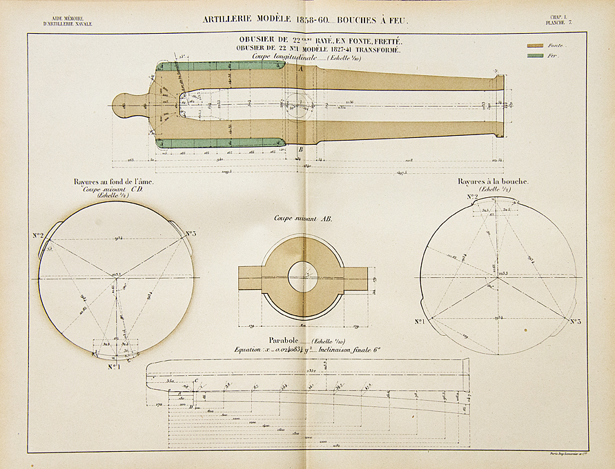
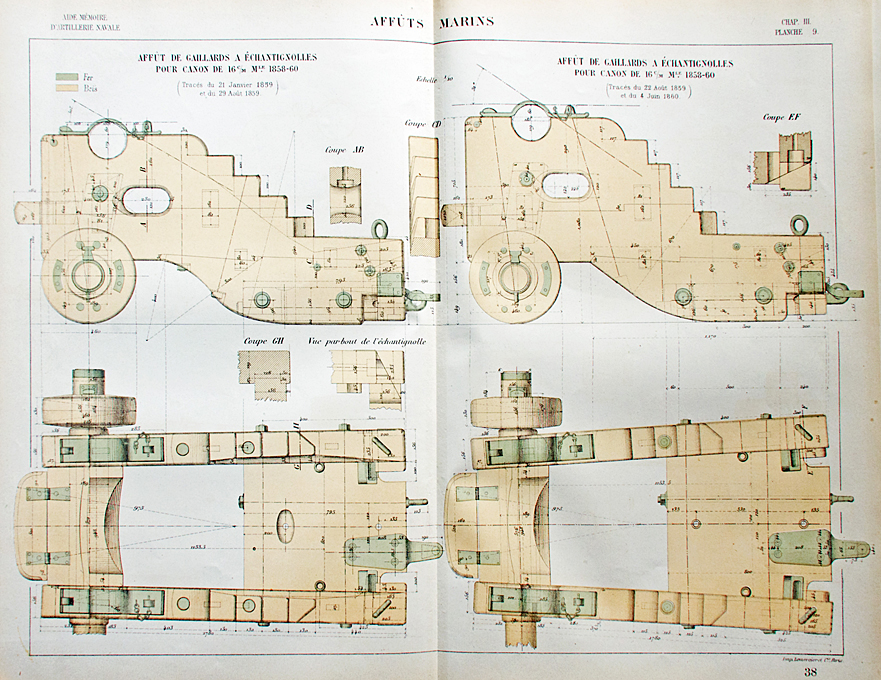
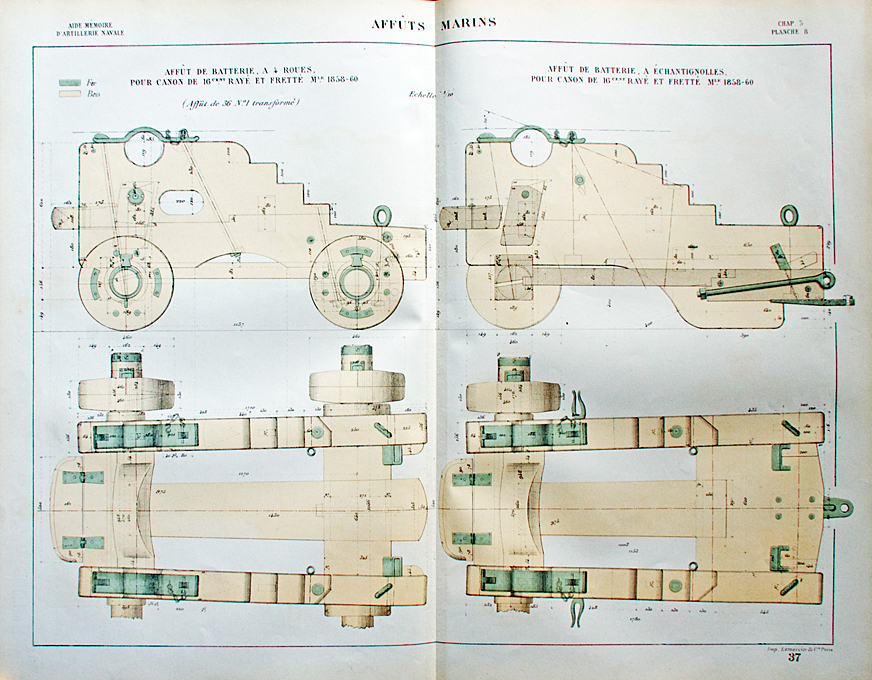
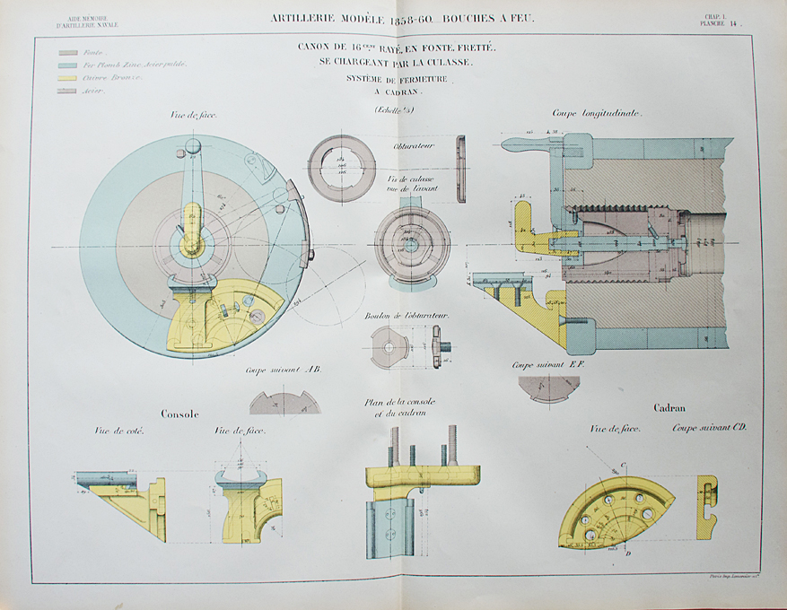
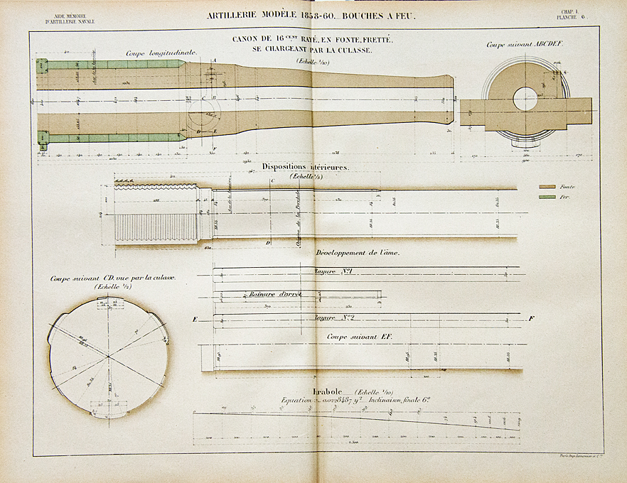
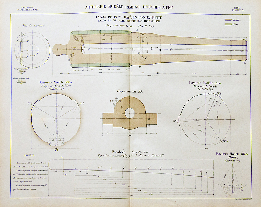
OK, I had a look into MINISTÉRE DE LA MARINE ET DES COLONIES [Ed.] (1873-1876): Aide mémoire de l’artillerie navale. which covers also the legacy guns that may have been still around in 1873. The most likely guns I have identified are: The 16 cm rifled muzzle-loader that was adapted from an earlier 50 lb cast-iron gun by turning down the rear part and shrinking on some steel reenforcing rings. The 16 cm rifled breech-loading gun that was also adapted from an earlier cast-iron gun by cutting off the rear end, and turning it down to receive steel reenforcing rings. Below is the lock for this gun: Depending on where both types of 16 cm-gun were deployed, there were different types of carriages. In the battery this type was used: While on the upper deck this type was used: The 22 cm rifled muzzle-loading gun was converted from an earlier howitzer in the same way as the 16 cm guns: Now for the carriage there are many different options in the literature. Not sure that the two guns were used as chase guns, as their barrel was relatively short. However, I have the feeling that they may have been mounted in pivoted slides. Once I know, where they had been placed on the ships, this will probably narrow down the choices. I have also detail drawings for the various accessories of the guns, such as breech-ropes, wedges, tampons, etc. If you need them, I can provide you with the higher-resolution scans. Just send me a PM with your email address.
-
Well, not really. It is just a jerk forward. I accumulated so many parts over the years, that in some cases I forgot what exactly they were meant for. So I decided to empty the many little boxes and put things together, at least to a stage, where they do not obstruct further work. And in some case parts have to be made fit to other parts in situ, which can be done only when the other part is permanently fixed. So, I am still far away from completion. I still have to make the boats and then comes the most dreaded part of all: rigging the two-chain-rail around the deck-house and the forecastle. That gives plenty of opportunity to screw things up. Also installing the boat-davits with the boats will be a challenge - I definitely will have to work from the middel of the ship to the outside to make sure I do not damage things.
- 888 replies
-
- 10
-

-
Thanks, David ! I think the manufacturer (formerly Röhm GmbH, then Evonik, but I think they have changed hands again) does give recommendations, I think for suitable solvent. Maybe Acetone works, I have to check. They also produce about three dozen similar formulations of 'liquid' Plexiglas with different viscosities and different curing times. The one I have here is a sort of allround one, good for constructing with Plexiglas, but as soon as it is hit by a quantum of light is gels - perhaps because I had the tube for over 20 years albeit it spent most of its time in the fridge. Another issue is that during my process the outside of the brass tubes was smeared, which is something I cannot have. They have slide smoothly into the boreholes. I think I will turn down some 1 mm Plexiglas-rod to 0.8 mm, which is the ID of the tubes, to a sort of press-fit. This was my original idea, but I thought the route via the liquid Plexiglas would be faster. I like Plexiglas because it can be polished flat to a glass-like finish.
-
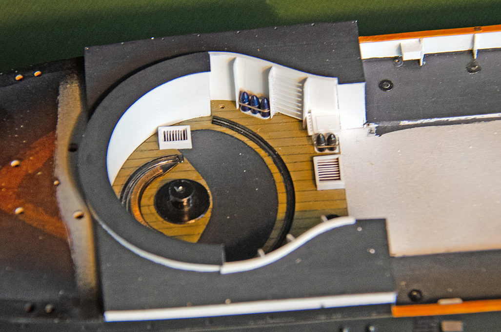
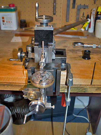
Thanks, gentlemen. These antique small machines are actually a secondary hobby, which justified kind of the expenses ... ********************** Fitting out the barbette As small update: I have further kitted out the barbette with the ladders that allowed the gun-crew to scramble over its sides into it and with the racks for the ready-ammunition. Also installed were the gratings over the stairs down into the crew-accommodation below the barbette (which also housed the cranking mechanisms for turning the gun) and over the hatch through which the shells would be lifted up. These gratings are somewhat conjectural, as the existing drawings could also be interpreted as showing stairs. However, I assume that hatch down to the turning mechanism must have been covered to prevent crew from tumbling down, but also open to allow voice communication with the guys cranking away. For the access to the shell-room, the grating must have been hinged in some way. There was a small gallows-like crane above it to allow the shells being lifted up. Also, there is a box in one corner with a kind of rack attached to it. Their function cannot be deducted from the drawings and the hand-written explanations are not readable in the scans available to me. Barbette with shell-racks, ladders and hatchways installed The next step will be to install the various portholes in the deckhouse and the hull. Their actual look is quite well-known, as one specimen has been recovered some years ago from the wreck of SMS SALAMANDER off a Dutch beach and which is now in private hands and of which I obtained pictures. However, on the model only a narrow brass ring will be visible from the outside. They were actually very small, only about 16 cm in diameter, which translates to 1 mm on the model. My idea was to dip thin-walled pieces of brass tube into Acrifix 192, as was done for the skylights, but this Plexiglas glue is too viscous to penetrate into the 0.8 mm diameter opening of the brass tubes. Have to figure out a different way … To be continued ....
- 888 replies
-
- 20
-
-
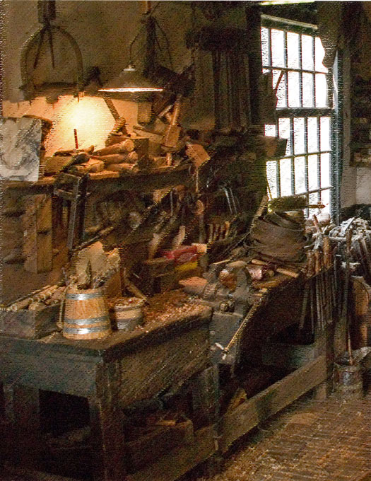
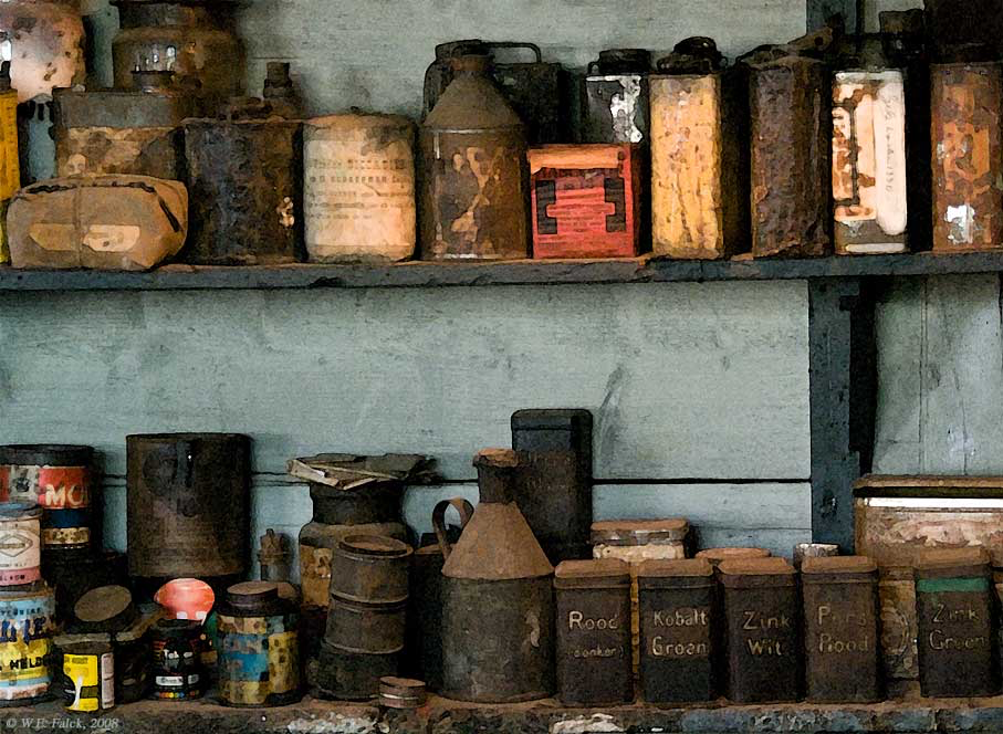
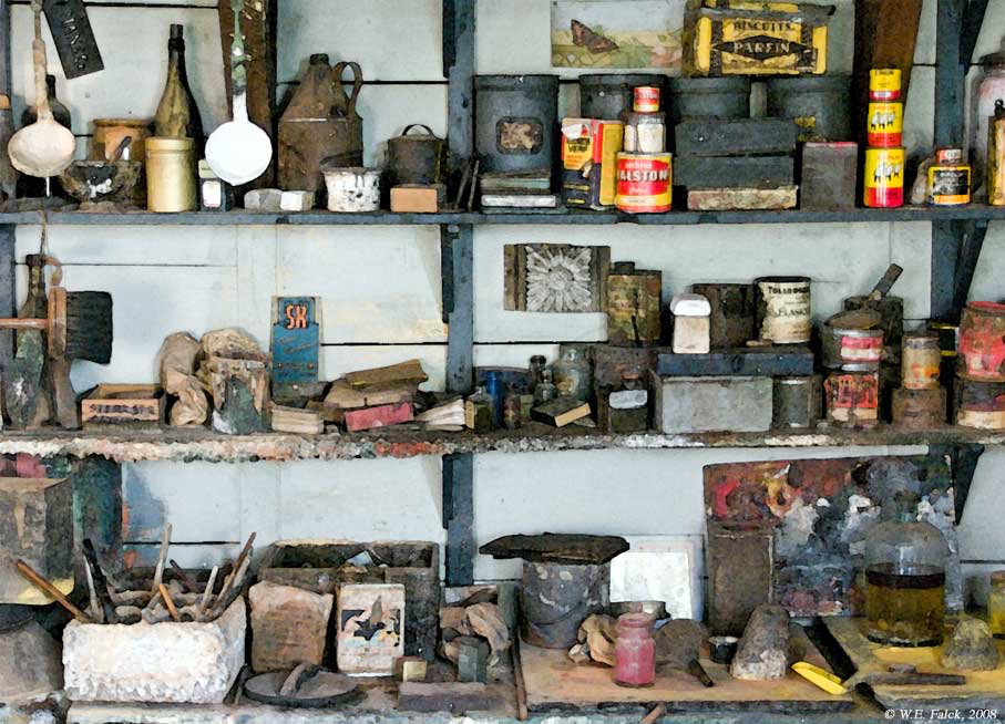
Love those cardboard-boxes, looking very convincing. It this sort of thing that enlivens such dioramas. I like to take pictures of old workshops and the likes in museums, as still-life in themselves, but also as inspiration for such models:
- 189 replies
-
- 15
-
-

-
NiCr-wire is used in heating elements e.g. for toasters, so it is available in a wide variety of diameters, but it is very tough to cut. 0.001" are actually 0.0254 mm - still very thin. McCaffery uses the twisted NiCr-wire for all his rigging, regardless, whether it was hemp or iron/steel. He also seems to paint all the rigging black, regardless, whether it is running or standing rigging. Personally, I don't quite like this idea, as suitable beige paints are available.
-
"Figure 153: Bottles (probably containing Eau de Cologne). They will be hanging on the wall above the sink." From the distance they look like the dispensing bottles for liquid soap. They were made either from glass (so that you could see the level of filling) or porcelaine. At the bottom there was a sprung valve (the sping is in the cylindrical part sticking out from the top). You pushed the knob at top to let soap out. In another variant you pushed the valve up with your hand underneath - the always leaked. Until the 1970s they were ubiquitous in railways, public toilets, hotels etc., when they were replaced by plastic bottles. Nice progress on little details ...
-
McCaffery was/is my bible for miniature ships, but his method of block-making is really only applicable to his rigid twisted metal-wire rigging. He basically punches out oval paper discs with custom-made hollow punches and then sticks these on both sides of the crossing between wires or he builds up tackles by glueing strands of twisted wire to discs. One could think of adapting the method by substituting thread for wire. It would probably work for simple tackles with single-blocks. Not sure how one would do with double blocks. I have tried to go (partially) down that route, but found it difficult to align the discs to each other with sufficient precision. Rather than punching the block cheeks, I cut them with my laser-cutter. So far, I managed to produce blocks down to 1.5 mm with miniaturised traditional methods, but will have to face making 1 mm blocks in the near future.
-
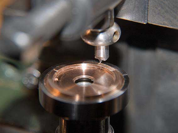
The rack was cut (a looong time ago) on my hand-shaper with a dividing head clamped to it: I ground a special cutting tool for this:
- 888 replies
-
- 20
-
-

-
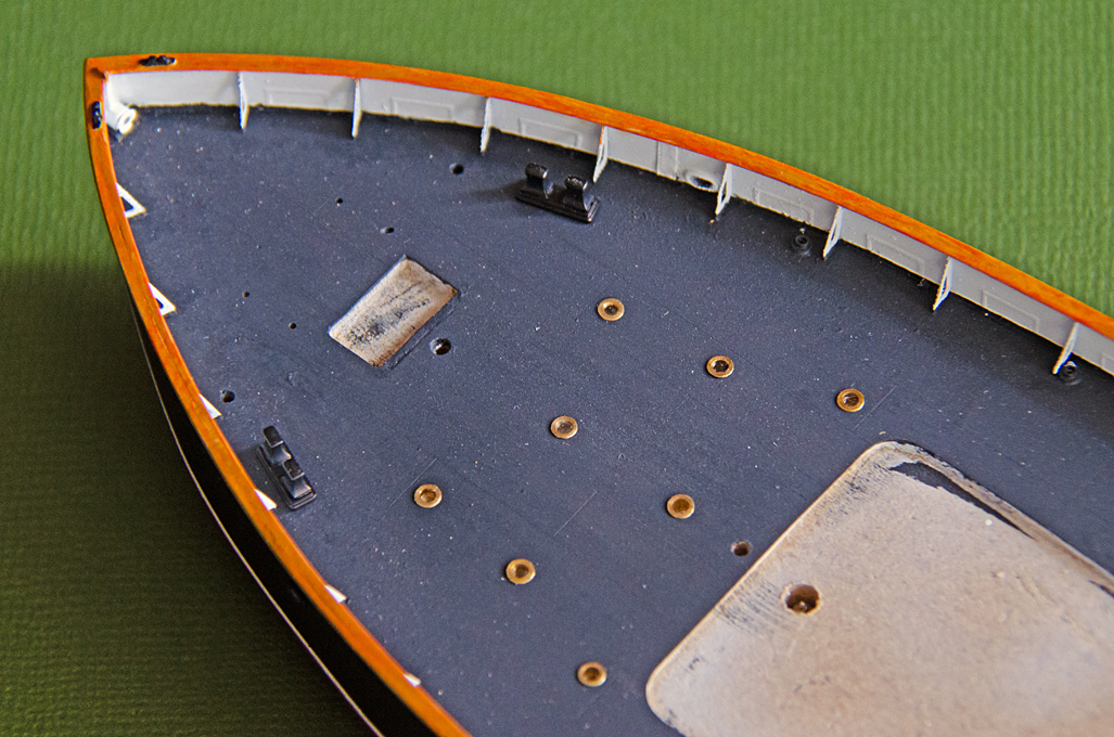
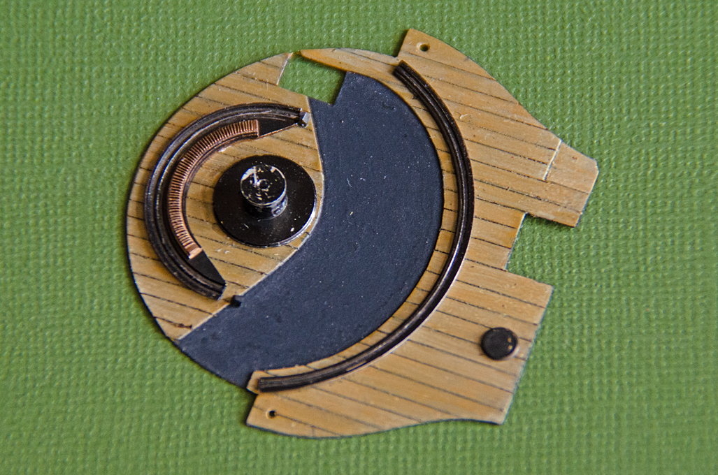
Thanks, gentlemen, for your appreciation ! ************************************* Kitting out the deck Painting the various parts takes quite a bit of time. Some parts can be spray-painted, while other parts need to be brush-painted because either they are difficult to mask for different paints or because the parts are too delicate for this. The deck of the barbette was fitted with the pivot, races for the gun and the rack that is used in training it. These parts were made a long time ago. The races are turned from steel, because I always think nothing looks like metal as real metal. Although, the races were probably rolled iron (like railway tracks), they looked to bright. So they were painted black all over and then the areas that likely show wear from the rollers of the lower carriage were rubbed with a lead pencil. In some areas also the paint come off again. Overall this gives the races a used look. The toothed rack was bronze and hence was made from bronze. There is also the lid of the opening through which the powder-charged was man-handled up from the powder-chamber beneath. Deck for the barbette with pivot and races for the gun installed The rear deck was fitted with the brass skylights that illuminated the quarters of the officers and other rooms. These were like portholes, but not moveable and had thick glass inserts. On the underside the inserts were shaped as multifaceted pyramids to collect and distribute the light from the deck above. The brass insert were turned and the glass simulated by pushing the brass parts into a drop of Acrifix 192 on a piece of smooth aluminium foil. The bright side of the aluminium-foils imparts a glass-like finish to the cured Plexiglas glue disc. I left the brass bright for a bit of contrast and interest to the deck. At the moment it looks to ‘model-like’, but over the years the brass will dull by oxidation to a more realistic colour and sheen – though I have no information on what they really looked like at that time. The glasses presumably dulled with time by the crew walking over them. It might have been better to imitate with a drop of white glue instead. The double bollards and coal-scuttles (not visible on the image) were painted black as per prototype and installed Rear deck with sky-lights and bollards installed To be continued ....
- 888 replies
-
- 18
-
-
... at least they put wedges behind the rear wheel, to keep the car from rolling off.
- 189 replies
-
- 11
-
-
Which first, hull or deck
wefalck replied to ubjs's topic in Building, Framing, Planking and plating a ships hull and deck
Personally, I tend to leave painting to the very end in order to not damage the paintwork during the building process. Other people paint as they go along, which perhaps also has motivational aspects, as you see something that looks like the finished model for a long time. In my case, the model may not look like much for a long time and then suddenly it emerges almost complete. It also depends on the accessibility of areas to be painted and the possibility to mask-off areas to prevent paint (or a different colour) from getting to them. -
Sailing ship often spent weeks or months in port, waiting for cargo or the right winds for their trips. After arriving and in suitable weather, the sails may be 'shaken out', hanging limp from the yards etc., which are not raised - in order to dry. According to old photographs, this was a rather common sight. And this is most difficult way of showing sails, as in this state the thickness of the material becomes really perceptible through the creases and pleats they form - most materials, even silkspan, are too thick to represent this convincingly.