


wefalck
-
Posts
5,562 -
Joined
-
Last visited
Content Type
Profiles
Forums
Gallery
Events
Everything posted by wefalck
-
Presumably for a roasting spit. In the Danish Rigsarkivet they have numerous drawings of galleys, not only Danish ones, and some show mechanisms for a mechanical turning of the spits. The galley is a major fire-hazard on a (wooden) ship and seems to have preoccupied significantly the navy responsibles, judging by the numbers of drawings and contemporary models that have survived.
-
 OK, as I am not going into commercial production, I am staying with my shop-made manual mill - but laser-shaping of the sheave would be nice.
 -
I gather you’ve used some kind of jig that allows you to zero-in each, the mill and the laser, for the consecutive operations. I understood that you index the billets manually in order to mill the four sides, correct? The milling wouldn’t be difficult with a ball-nose mill. Laser-cutting the sheave certainly lets you go down one almost order of magnitude in size.
-
Well, I missed this thread since last summer. Don’t have a suitable laser-cutter, but thought by adding a 4th axis, i.e. an indexer, and modulating the laser power, one could do exactly that … You don’t have to worry about breaking milling cutters and could down to dimensions, where it would difficult to find suitable cutters. I am thinking of 1 to 2 mm blocks …
-
This is going to be a brilliant model and the 'fake' metal looks really good. OK, with hindsight, but I wonder, whether it would have been possible to 'joggle' the vertical joint in the boiler-lagging. In this way, the outside diameter would have not increased due to the extra thickness of the overlapping material. I had to check the imperial thread sizes, but to me they are not actually that small at 1.2 mm and 1.8 mm diameter. Anyway, it may have been a good idea to re-thread the cast parts with an appropriate die to remove any flash or distortions. In theory, one can also use a very fine triangular file to remove flash and burrs, but it is not so easy to find a fine-enough file for these fine pitches. The problem is that you do some sort of pressure-forming, when screwing the nut on and that requires a lot of force to move the material.
-
It's the 5th painting in the list: https://www.invaluable.com/auction-lot/arr-frank-j-h-gardiner-british-b-1942-20-c-c0040f1930 BTW, I just saw that it was auctioned by Charles Miller in London. He is a nice knowleagble and helpful guy (ex-Sotheby's if I remember right), you could send him a picture of yours and ask his opinion.
-
This method certainly results in a quite accurate copy of the curve. However, it appears to be rather elaborate. In effect what you do is, you trace onto a rough-cut template a line that is parallel to your target curve. So, there may simpler methods to do this. Boatbuilders fitting planks use parallel scribers for this: they clamp the new plank into place and then trace the edge of the already fitted plank onto the new one below. Perhaps a compass where the legs can be locked in position could be used: at each frame location you draw an arc onto the template and then connect these arcs with a tangent line, which should be an exact image of the target curve. Or take a short, rectangular piece of wood, put a short piece of dowel as a handle on it, hold this against each frame and draw a short line onto the template on the opposite side. Finally, connect these lines to get the image of your target curve.
-
When you take it out of the frame and look at it at an glancing angle you should be able to see some texture in the paint, particularly in those areas that appear to have been worked over indeed in gouache (e.g. the blue bulkhead panels, the coat of arms, the white heads of the waves, etc.). Gouache form a matt layer on the paper. If you go down this list of paintings in past auctions by the same painter: https://www.invaluable.com/artist/gardiner-frank-joseph-henry-bz4rerv65l/sold-at-auction-prices/, you will see in Lot 20 a very similar landscape in the background. You could also compare the style of the sea and other features. This painter is not be confused with the better known Derek Gardner, who paints similar subjects.
-
The stems / ram-bows of iron ships are quite pointed actually. I would guess that the outer edge was not more than perhaps 4 inches wide, which means that it would be only 1/16" in 1/72 scale. Not sure that this will be stable enough in plywood. I would cut the profile of the stem from aluminium and glue it into a slot cut into the plywood. As matter of fact, it may be worthwhile to make also the stern-post in that way. With such a big model, you have to think about the stability of the 'backbone'. These ram-bows became very fashionable after their use was partially successful in the Battle of Lissa between Austria and Italy and the Italian Re d'Italia was sunk in this way. Until the end of the century virtually every naval ship was given such bow, even small units such as torpedo-boats.
- 104 replies
-
- 10
-

-
As a matter of fact, Penzo discusses several of the boats, not only trabaccoli, moored in the canal of Cesenatico. Unfortunately, I have never been to that part of the italian adriatic coast (yet). I only made it to Chioggia, were they also have a couple of old boats in the harbour.
-
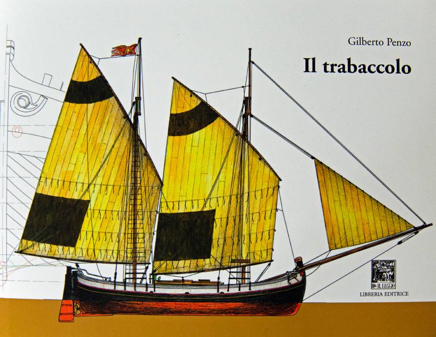
A couple of week ago I happened to be again in Venice. My wife has a good friend there and we try to spend a few days in this wonderful city every two or three years. Whenever I am there, a pelerinage to various maritime spots is obligatory for me, while the ladies are chatting or shopping. This pilgrim's tour include the (work)shop of Gilberto Penzo (www.veniceboats.com), one of the experts on the Venice region boats. This was the opportunity to buy his latest book directly off himself again: PENZO, G. (2020): Il Trabaccolo.- 230 p., Sottomarina (VE) (Il Leggio Libreria Editrice), Price 45€, ISBN 978-88-8320-179-0. The trabaccolo was once one of the most important ship-types that transported goods up and down the Adriatic. Today only a few specimens have survived in a more or less well-preserved condition. Penzo's book is a comprehensive account of this type and its history, based on a systematic evaluation of the available sources. It begins with a critical evaluation of pictorial representations from the early modern period to the drawings in Pâris’ Souvenirs de la Marine. Models of trabaccoli from different eras were also examined. Penzo then deals in detail with the various design methods of the shipbuilders of the time and the instruments used for it. Some still existing trabaccoli, albeit in a modified form, or their remains made it possible to take off their lines and make other measurements using modern methods, such as 3D-laser scanning and generate virtual 3D-models with it. The book contains a number of elaborated lines drawing in A4 format, which are perfectly suitable for building small-scale models. The author also offers large-scale drawings for sale (www.veniceboats.com). A separate section is devoted to the shipbuilders and their building sites. Naturally, this then leads to a discussion of the materials, techniques and tools used in construction. The latter in particular are shown in great detail with photographs. This serves as an introduction to a detailed description of the construction itself, based on structural analyses of still existing trabaccoli and wrecks. Further sections deal with the external appearance, especially the apotropaic elements, such as the ochi (bow eyes) and pelliccioni (the 'fur caps’ on the stem-post). Of course, there is also a large space dedicated to masting and, above all, the sails. The sail-plans have changed significantly over time and the cuts and making of the sails are discussed in detail. Even if the construction sites were simply equipped, as everywhere during the times of wooden shipbuilding, a short section is devoted to them, as well as to the maintenance work that was also carried out there. This then leads on to the last section, that is the restoration of the last remaining specimens. Thanks to the wealth of illustrations and drawings, this well-founded and comprehensive book is also accessible to those who have little or no command of Italian. Drawings with the names of the individual components in Italian are very helpful in this respect.
-
This depends on the circumstances. I would assemble a model (from scratch or kit) as much as possible before painting with two provisa: - when two colours abut to each other, it is better to paint first and then assemble - gives a cleaner colour separation line - that all surfaces that need to be painted must be accessible afterwards If two painted surfaces are glued together, the joint will only be as strong as the paint adhering to the surfaces, this is one reason for assembling first. Small parts are easier to paint when in place. Leaving it on the sprue would solve that problem, but handling during separation and subsequent clean-up may damage the paint again. I rarely prime, as any additional layer of paint tends to obscure surface detail. On the other hand, a primer makes imperfections very visible. Also, when brush-painting plastics and metals without priming it may be difficult to achieve an even first coat. I am mostly spray-painting and here the first thin coat effectively acts as kind of primer.
-
Do you have any machine tools, specifically a lathe ? Here is building log of a colleague of mine, where he shows step by step how he makes a similar windlass: https://forum.arbeitskreis-historischer-schiffbau.de/viewtopic.php?f=16&t=2230#p28040 (not sure, whether this is visible without registering. Apologies in this case).
- 17 replies
-
- 1
-
-
- windlass
- Dutch model
- (and 2 more)
-
Brian, I didn't look over the two logs in detail again, but from what I also remember, Eric used the pastels mainly for weathering or toning, not as body colours. Of course, if you add a binder, e.g. lineseed oil or shellac to pastels, you would use them just as pigment. Below is an example from my own production of weathering over acrylics - salt stains and general grime, done mainly with white pastel:
-
I would make it in five parts or actually three, as two of them will be cut in half to make two: - the larger diameter central sections with the ends sloping towards the thinner section - the smaller diameter outer sections with the pointed ends for the cone bearings of the barrel (it is interesting that the Dutch used cone bearings for the windlasses of their small craft until the beginning of the 20th century) - the ratchet wheel (which may actually be faced by two 'washers' in addition as per your drawing) Mark the centre of your (square) stock and drill for metal pins before you start shaping the pieces. This gives you a reference so that everything is concentric, when assembled. For the thinner part I would initially shape the 6-/8-sided barrel and then cut this into sections. Shaping the square holes for the handles is difficult, so I would cut each side into three sections, file slots with square cross-sections into the end and then glue this together again. The pointed end I also would shape only then.
- 17 replies
-
- 1
-
-
- windlass
- Dutch model
- (and 2 more)
-
I have never seen pastels be used for actual painting, in modelling that is, but only for 'weathering'. Modell building suppliers have created special sets for different areas of model building, but I happen to have a big set of artist's pastels. However, a few basic pigments should be sufficient, namely black, white, red and yellow ochre, and burnt umber for our needs. Pastel sticks can be bought separately. Rub off a small amount on a piece of sandpaper for application by brush A good tool for applying pastels are also these little foam-brushes ladies use to apply make-up - after all powder-based make-up is nothing else but pastels.
-
Was it only soft-soldered ? I gather the wooden jig would go up in flames, if you tried silver-soldering ...
-
Pastels may be a route to go. If you don't like it, you can wipe or wash them off (not so from bare wood though). They can be applied with a bristle brush or cotton swabs and the effect can be build up gradually. Finally, they can be fixed with a light mist of matt varnish.
-
P.S. the decades between 1850 and 1880 have been experimental years, during which the naval ship gradually evolved from sail-carrying wooden walls to something close to the modern steel battle-ships. Nations experimented with hull designs and gun arrangements. The French have been particularly inclined to come up with some rather 'steam-punky' designs looking back. Have you noticed also this interesting building log here: They have been particularly fond of excessive ram-bow designs, as here on the ill-fated aviso LE RENARD (1865): https://fr.wikipedia.org/wiki/Le_Renard_(aviso) Perhaps no accident that Jules Verne was a French, born in Nantes into a family with shipping background and that his main works were written during those decades.
-
I think there are several cottage-industry manufacturers in Germany that offer such bricks made from polymer-clay in model-railway scales. I can't put my finger on the company's name, but I seem to remember that there is also one that sells silicone moulds to make them yourself.
-
There is a German colleague, a retired engineer in Bavaria, who currently builds the BRETAGNE (1855) in 1:75, a massive model nearly 6 feet long. You can see his building log on our German forum (but you may have to register as guest): https://forum.arbeitskreis-historischer-schiffbau.de/viewtopic.php?f=16&t=1548. As an engineer, he uses all sorts of advanced techniques, outsources some parts, and recently mastered 3D-printing with UV-curing resin himself. The latter he uses to make masters for various hardware items that then are professionally cast and sold to others by these guys: https://elde-modellbau.com/epages/bd40fd5d-0ba8-443f-857a-537621b491ae.sf/en_GB/?ViewObjectPath=%2FShops%2Fbd40fd5d-0ba8-443f-857a-537621b491ae. The parts are in 1:75, but some of them you might find useful anyway. Don't know about having them sent to the USA. Before that, he built the NAPOLEON, another massive model at nearly 5 feet overall: https://forum.arbeitskreis-historischer-schiffbau.de/viewtopic.php?f=16&t=1523&p=15013&hilit=NAPOLEON#p15013. How are you planning to present the model, as 'builder's model' or realistic ? I always liked the way how these large models in the Musée de la Marine are done, with the armour in bright steel, the coppered underwater body, while the stern-post etc. is cast in bronze to avoid electrolytic corrosion of the copper-cladding.
-
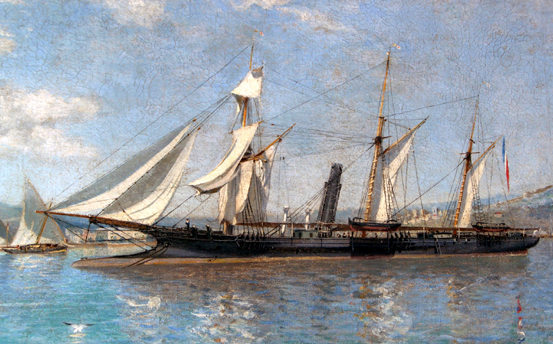
Good choice. I have weak spot for those iron-clads at the transition from sail to steam ... Here is my collection of images from the Musée de la Marine in Paris in its old set-up, plus a few from the models in their Toulon and Rochefort dependances: https://www.maritima-et-mechanika.org/maritime/paris/frenchironclads.html. If you want copies of the original resolution images of SOLFÉRINO, let me know your email-address by PM and I can send them to you via WeTransfer. They will be unprocessed (for the lighting the poor lighting conditions) and you will need to brighten them up etc. They are also rather pixelated for that reason. I also have 'official' drawings of the armament she would have carried. If I know the type of gun, I can look up the drawings for the barrels and the carriages and make scan available to you. However, I have the feeling that not much of the guns will be visible and she carried little on her upper deck, I think. Of course, other navies of that time had also iron-clads and some of them are quite well documented, say the Spanish NUMANTIA, on which there are various books and kits also I believe: https://www.maritima-et-mechanika.org/maritime/madrid/madrid.html I will keep a tap on this project 👍
- 104 replies
-
- 12
-

-
-
Oh, I am constantly looking for inspiration in other areas of model-making and new products also from other areas than modell-making ... Not sure that mould-making for 1 mm-blocks would actually work, at least not with silicone.
-
This problem has been nagging me for decades actually. So mentally at least, I probably have been through most of the ideas: - making a set of dies to shape a block from soldering tin around a wire - inspired by the lead seals you see on electricity meters and the like; could work for larger sizes, but it would be difficult to pull out tiny wires, even when you use tungsten or NiCr. - same idea but using the dies to shape a ball of two-part expoxy (Milliput or similar); same problem with releasing the wire when set or distorting the block, when pulling it out while the epoxy is still soft. - casting in some resin using silicone moulds with wires embedded to keep the hole open; again releasing the wire is the problem. The last two methods would allow to imbed internal strops relatively easily. Somehow, I came to the conclusion, that some rough-machining with good old hand-work in some reasonably hard and dense material (I prefer bakelite) is the solution - unless ... - I have tried to entice a colleague for some time now to design some blocks and print them in his UV-curing resin 3D printer, but he hasn't got around to do it yet. Even if the printing doesn't keep the space above the sheave completely open, re-drilling it is much less work. All the grooves for the rope strops etc. would be formed on already, of course. Making rope-stropped blocks is much less of a problem than internally stropped ones. However, one could 3D-print them, then add the wire-strops as per Wingrove's method and fill/seal the grooves with a tiny blob of UV-curing cement.
-
Again, excellent paint-job !