


wefalck
-
Posts
6,526 -
Joined
-
Last visited
Content Type
Profiles
Forums
Gallery
Events
Everything posted by wefalck
-
It indeed evokes the feeling that the crews on these little ships crossing the oceans were all on their own ...
-
 How were they launched in the US those days? I know of several European paintings of the same period, where the ships were launched fully rigged with sails on etc., I mean new ships, not ships hauled out for repair. May look unusual to the modern eye, but would allow one to show the rig too.
 -
Oh yes, I forgot about her wheel. That makes perfect sense to show it with a mirror underneath ...
-
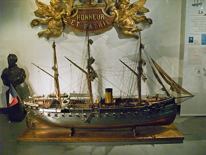
The museum's model is barque-rigged. Shown below in the old setting, before the museum was closed for refurbishment.
-
The AAMM plans for LA GLOIRE are based on the large-scale model in the museum's collection and various contemporary plans.
-
Looking very impressive indeed 👍 I actually thought that she would be sitting directly on the board, evoking muddy waters around her, as someone was hinting at above.
-
I suppose in your area the local softwood, such as pine or cedar would have been used, as it was abundant and easy to cut into planks.
-
Ausgezeichnet ?
-
Things evolved differently on both sides of the Big Pond and in the various European countries. I was quite astonished to see, when I first started to go to England in 1972, that even young office clerks and the likes would wear three-piece suits - mind you they often were in dark green, brown, bourdeaux and with (slight) bell-bottoms at that time. Also ties were of the 'plaice' style and colourful. At the same time the suit had almost disappeared almost everywhere in my home country, Germany. It had a brief revival in the early 1990s, but generally badly cut with too long sleeves and hanging shoulders ... When I moved to the UK in the mid-1980s, many (if not most) 'white collar' workers above 30 or so wore ties in the office, however shabby they might have been dressed otherwise. My father to the very end normally wore white shirts and a tie. Allowance was made during vacations, when travelling, when the shirt could have been grey or blue, but jacket and tie were always there. Sic transit gloria mundi ... or as Karl Lagerfeld seems to have put it: "Them, who wear track-suits, have lost control over their lives". As to workplace-safety: when working with machinery, my father always rolled up the shirt-sleeves inside. Apparently, he was taught this by his father, who was a trained locksmith and mechanic. And: What is the difference between the UK and Germany? British men, when sitting down in a meeting room take off their jackets and loosen their ties; later, when going to the pub they straighten their ties and put on their jackets. In Germany it is the other way around.
-
Carbon-tetrachloride production has been banned worldwide since 1999 (Montreal Protocol).
-
Are you going to skim over the horizontal flats in situ - this seems to have been the practice on all the chucks I have for my lathes, judging by the shape of the edges of the jaws. This ensures that the flats run perpendicular to the axis of the lathe.
-
You didn't have an 1/16" end-mill ? That would have been another option for milling the slots into the jaws. Or to make a low-profile saw-holder that uses an internal thread and a screw to clamp the saw. Putting a plate in front of the chuck-body is avoiding to have to use a T-slot cutter, but from an engineering point of view is a weaker design than a solid body.
-
Indeed, and I would not use it on thick stock, where lots of material is to be removed. However, I am using sometimes the 20 to 40 mm diameter versions on the saw table of my lathe for thin stuff. Make sure you get a cutting-saw, that is one where the coating is on the rim and extends some mm on the side surfaces. Disks that are covered all over in diamond are for grinding and may get stuck, as there is no clearance when you feed them in further.
-
I think Underhill's book has a sketch for this arrangement, but I may be mistaken, as such detail drawings are a bit dispersed around the book. Basically, the eyesplice of the block is fed through the cringle and then turned over it - a simple, straightforward operation, but difficult to describe ...
-
Internally stropped blocks are mechanically a better solution, because the iron strop support the axle closer to the sheave. However, I think, they only became practical, when rolled iron bars became available in larger quantities from around the second quarter of the 19th century on. Calibrated iron bar allows to mass-produce the block-shells on machines, as the slot for bar can be milled to a given dimension, rather than being fitted to each strop. Internally stropped blocks would be found in locations, where heavier strain is expected and where there is no risk that they would chafe sails. In locations where the latter may be a risk, rope-stropped blocks were preferred for a long time. Underhill's book on rigging would be an appropriate source for the 1860s details.
-
On the Internet you can find all sorts of sizes and grades of diamond-coated cutting saws. They are not only used in tile etc. cutting, but also for cutting gem-stones.
-
She looks elegant in her frames 👍
-
As these protrusion serve to preven the eyes of the topping-lifts from slipping inward, they should be 90° off-set compared to the direction of pull of these.
-
I wholeheartedly agree that for an iron or steel ship metal (brass, copper) or some hard plastic (bakelite paper) is the material to go for. It best represents the metal surfaces. I found that thin sheet metal can sawed more easily with the saw-blade in reverse, at least for fretsaws. I haven't tried this with circular saws. In this way there is less a tendency to hook do to uneven manual feed. Nice metalwork on forecastle, btw. !
-
My material of choice is a fast-drying solvent-based varnish that is sold over here in Europe as zapon-lacquer. In composition it is rather similar to solvent-based nail-varnish. Apart being fast-drying, i.e. within minutes, it has the advantage that you can undo any knots with a drop of solvent (acetone) should the need arise.
-
One possibility to duplicate parts, such as the shell is to use a shaped turning bit. This can be ground from a piece of old hacksaw-blade. You would need a bit of a clearing angle, but no top-rake for brass. One would rough out the shape with normal turning tools and just give the part the final shape with the shaped bit. Coming on nicely, the model !
-
Screw it well down, the base for the 3-pounder-QF - according to the video, when they first tried it out, it flew off the boat taking the crew with it ...
-
Small bench-lathes typically had an external spindle cone in front of the spindle thread. The chucks or the back-plates then had a matching internal cone. I think your spindle nose is too short to add this feature in retrospect. When used with collets, the spindle-thread was usually covered with a brass ferrule as protection. Small watchmaking lathes only have internal spindle cones (as used for collets) and the chucks are mounted on arbors that have the same body as the collets (and are pulled in with a draw-tube). While this is too weak for heavy work, it gives the best concentricity for interchangeable chucks.


