


wefalck
-
Posts
6,644 -
Joined
-
Last visited
Content Type
Profiles
Forums
Gallery
Events
Everything posted by wefalck
-
 Nice drawing - one doesn't see hand-drawings that often anymore theses days. The yards actually look quite narrow. The main course (Breitfock) then appears to be rather narrow and heigh. Top- and topgallant-sails look more in the typical proportions.
 -
Harriet McGregor by Boccherini
wefalck replied to Boccherini's topic in - Build logs for subjects built 1851 - 1900
Looks actually very nice! Ship-shape, Bristol-fashion! For me PVA (white gule) would be the standard glue for wood and I would rather not use contact cement. The latter, due to its high viscosity, sits on the wood surface, while PVA 'keys' into the wood-grain. Such bonds are virtually impossible to separate without ripping the wood into pieces, while bonds with contact cement can be sheared/pried off. One solution to deal with moving parts, such as the roof panels, is to glue them on a piece of silk-paper and once set, to glue the assembly in place. I would also make it oversize and then trim/sand to an exact fit. It's easier to deal with one problem at a time. -
Harriet McGregor by Boccherini
wefalck replied to Boccherini's topic in - Build logs for subjects built 1851 - 1900
It's noise only, I suppose, when you are milling wood at high-speed. When milling metal, you work at much lower speeds and hence less high-pitched noice. -
Harriet McGregor by Boccherini
wefalck replied to Boccherini's topic in - Build logs for subjects built 1851 - 1900
Excellent approach! Some people also glue sections tangentially and cut to form a hexagon, or rather two hexagons offset by 30° for added strength, to better represent full-scale practice. -
Indeed, I have been (partly) following Joe Pies' lathe-project. He currently works on the shaper by PM Research. And yes, Stuart's kits in a way are more 'authentic', as they use cast iron, rather than aluminium.
-
So Stuart dodged making proper thrust-bearings ... normally, the bronze bushings would have tapers turned/ground into them, to which tapers on the spindle would correspond. The double nuts then would take out the end-play from the spindle. I gather this would have been quite a challenge to make and this is 'only' a model anyway. Nice machine machining, as always 👍, btw.
-
Harriet McGregor by Boccherini
wefalck replied to Boccherini's topic in - Build logs for subjects built 1851 - 1900
Yep, jigs are a 'professional' approach to making and installing things (though personally I am often too lazy to do it ...). Copper wire is indeed too soft normally to be turned. One can try to strech it to 'work-harden' it by holding one end in a vice and give it a jerk with pliers. However, it general it is difficult to work on leghts greater than two times the diameter. The same applies to most brass. I found that using small brass-nails as starting material helps - the nails are sort of drop-forged and this hardens the material. The general recommendation is to not turn unsupported pieces that overhang more than three times the diameter. With steel you can get away with more, with copper a lot less and brass or wood are somewhere in between. For longer workpieces one needs a dead centre in the tailstock or a fixed steady. A question: did you use the template to form-turn the balustres or just to control the shape, while turning with a normal tool? I am asking, because you seem to have it mounted to the rear. -
sail plan for Ballahoo (Fish class) topsail schooner
wefalck replied to georgeband's topic in Masting, rigging and sails
Topsail-schooners tend to be smaller ships that were sailed with small crews, perhaps a maximum of eight or even less. So the question is, whether they actually bothered with clew- or bunt-lines on topgallants at all, or rather struck them completely, as they may have been set 'flying' anyway. This would depend on time-period and region, of course.- 22 replies
-
- 2
-

-
- caldercraft
- jotika
- (and 4 more)
-
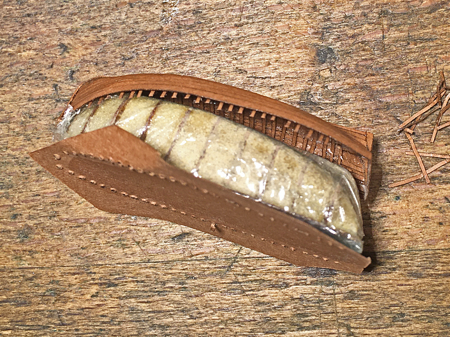
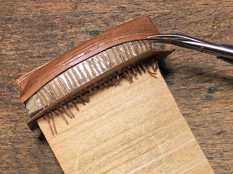
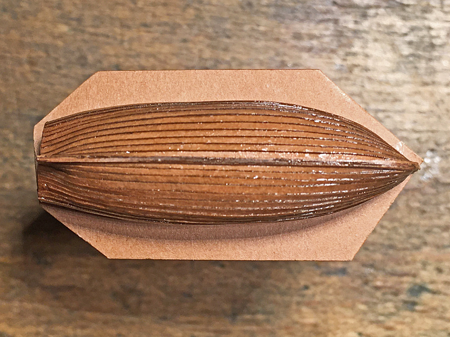
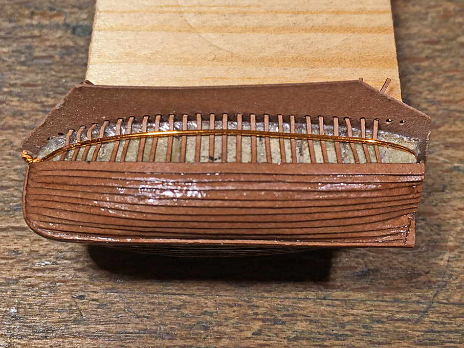
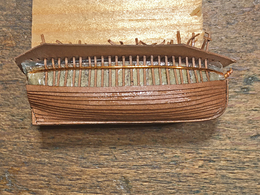
Thanks again to all your encouragement and praise 😇 ********************** Jolly-Boat continued 3 The moment of truth: I removed the copper wire and cut the extended frames with my micro-scissors. Cutting the extended frames with micro-scissors With some cautious rocking of the shell, it came off cleanly. The result is a quite strong hull with the typical exterior and interior look of a clinker-built boat. Unfortunately, some of the frames have moved a bit, but with a drop of acetone this can be fixed. Hull begins to detach from the former I noticed, that the frames did not glue well to the wash-strake, which is actually good, because on the prototype they did not continue to this strake, but ended under an in-whale. I will have find a way to cleanly cut the frames at the appropriate height and then continue with installing the cant-frames, in-whales, floor-boards, seats, etc. Hull successfully taken off the former I am actually wondering now, whether I could have assembled the hull in traditional clinker-fashion, with ‘edge-fastening’ the strakes only and then inserted the frames prototype-fashion afterwards. On the other hand, gluing the stem-keel-combination to the tied-down frames gave a rigid back-bone to work from. So this was probably the best way. To be continued ....
- 935 replies
-
- 20
-
-

-
Harriet McGregor by Boccherini
wefalck replied to Boccherini's topic in - Build logs for subjects built 1851 - 1900
Quite a way of making round-head pins ... I used to chuck up brass pins into my handheld electric drill and shaped the head with files (now I do it on the lathe ...). -
Yep, that's going to be a fun project! Making a one-of indeed requires a lot of imagination for set-ups and work-holding. In the factory, they normally used jigs and gang-milled or line-bored matching parts. Time-efficient, when set-up time is bigger than actual machining-time and also ensured that parts often were interchangeable. When turning bushings and the likes, I would only use twist-drills at the very beginning and finish off the hole using a boring bar. This avoids oval, conical and off-centre holes. The boring-bar should be as big as the hole permits to reduce flexing. The effect of flexing can be removed by running the boring-bar through the hole a couple of times without feeding in. Pulleys for flat belts are indeed always domed, one can see that even on my PROXXON bench-drill ...
-
Talking about 'upgrading': once you have a mill, you can make lot's of accessories yourself, special ones and replicating standard ones to suit your own requirements and ideas ...
-
If you use a fast-drying and solvent-based lacquer instead of glue, this will solve a lot of the problems, as any knots and hanks can be softened and adjusted just with a drop of solvent ...
-
I gather, oneself is one's worst critic ... and being critical of one's own work gives one the means to do better next time. The most difficult thing is to overcome one's own impatience to get things done 🤔 My problem often is that I work so slowly (also because 'real' life gets in the way all the time) that I often keep forgetting lessons learnt by the time I should use them again 😬
- 935 replies
-
- 13
-
-
Both smell very nice and fruity (amyl alcohol) 😇
-
Thanks gentlemen ! I actually realise, how this not so even planking happened. On one hand, I didn't look too carefully at the running of the planking on the starbord bow-section, being mainly concerned that the planks on both sides meet properly - negligence. On the other hand, the stern area was not fully filled with the core and there was a too large gap between the last frame and the transom - it was difficult to align the planks without pushing them in. At this small size it was also difficult to mark out the runs of the planks beforehand, so I did everything 'by eye'. This got me into trouble in the transition area between the stern-post and the transom, where on this boat there is quite a small-radiused transition curve between both. Perhaps I should have had a narrower plank at that point. For technical reasons the planks are wider than one would have on the prototype: the small scale-overlap was just not achievable, particularly as the edges could not be bevelled. Perhaps working in thin veneer or styrene would be better than using paper, but my cheapo laser-cutter cannot handle such materials, it jut doesn't have enough power for it.
-
As noted earlier on, old-style nail-polish is essentially the same as what is sold over here in Europe as zapon-lacquer (to protect polished metal surfaces mainly) and I use it on everything.
-
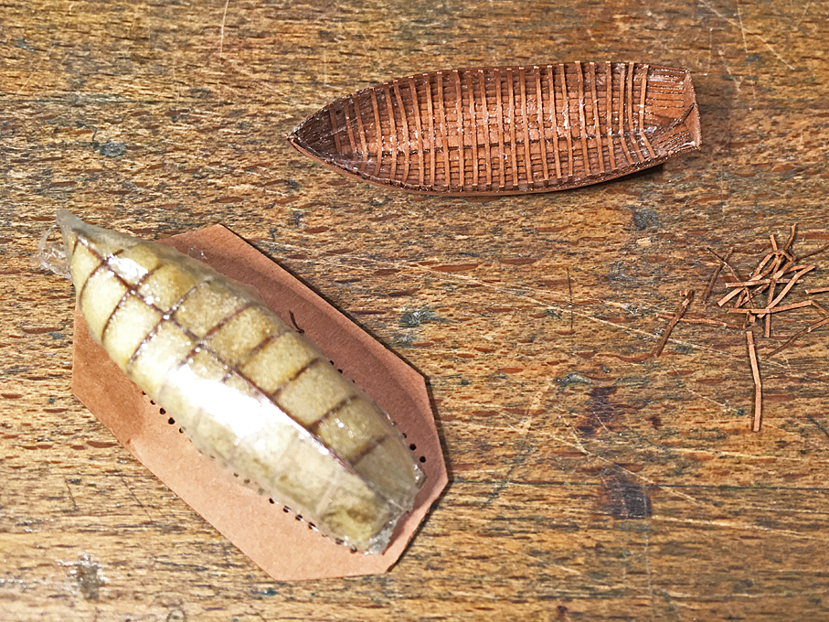
Jolly-Boat continued 2 Just a short update to show that the planking as such is finished. I am not 100% satisfied with my work. The plank widths could/should have been more equal, but I somehow struggled with the shape of this boat more than with the others. Also, it was easier to glue the planks to the solid core than just to the framework and the edge of the plank underneath. Jolly-boat starboard side – overall length is 36 mm After the planks were on, a doubling for the keel and stem was attached to both side, kind of faking a landing of the planks in a rabbet. Jolly-boat port side There are several little gaps and other imperfections that need to be touched up with a bit of putty, but I will do this only after having separated (hopefully) the boat from the former. The putty is quite brittle and my fall out during the procedure. Looking down onto the planking Once the boat has been released and the frames trimmed back, the wash-strake can be sanded to its final width and shape. Some additional (cant)frames will have to go in before the further fitting out can begin. To be continued ....
- 935 replies
-
- 23
-
-
-

-
You should make a little film with a video-endoscope to appreaciate all this work !
-
Excellent rendering ! Only two things are missing: the trigger and the finger-guard at the pistol-grip 🤪
-
Sail also stabilise a ship in more severe weather, but I gather the main purpose was an insurance against the frequent engine problems in those early years of steam propulsion.
-
Most you ever want to know about gaff rigs is explained in LEATHER, J. (1977): Gaff Rigg.- 272 p., London (Granada Publishing). There are indeed standing and lowering gaffs as Bob explained above. In general, boom-less gaff-sails (as in GREAT EASTERN) were typically rigged with standing gaffs. There would have been no place to store the gaffs in the absence of booms.
-
These were the forerunners of linoleum - Walton (the linoleum inventor) wanted to make something more durable than these oil-cloths. One can imagine that they wore through quite quickly when walked over with street footwear.
-
Thank's gentlemen! Actually, this technique of building has been described in the classic works on POF, think Underhill or Curti, I just translated it into different materials and some modern tooling. The copper wire to keep the frames down was an emergency solution, when I realised that the frames would not follow the core due to the slight tumblehome of hull. I first tried thread, but twisting the wire pulled it nice and snug around the template.