

modlerbob
-
Posts
0 -
Joined
Reputation Activity
-

 modlerbob reacted to moflea in Union by moflea - FINISHED - Constructo
Here is my first pictures of the work:
I tried first to paint it with some spray acrylics but I didn't like the way it came, so I sanded it again. The picture above shows my first painting attempt.
-
modlerbob reacted to mtaylor in 20 Gun Frigate by DSiemens - FINISHED - BOTTLE
Nope, not going to like that post... I hope your tricks work.
-
modlerbob reacted to DSiemens in 20 Gun Frigate by DSiemens - FINISHED - BOTTLE
Thanks every one. Almost done.
-
-
modlerbob reacted to Jim Lad in Rigging Ratlines
Bob, she certainly had rope ratlines during her working life, but if you are modelling her as a training ship in the 1930's, then boards would be correct, as shown in the photos in Nepean-longridge's book. I believe that she also had other rigging changes at this time, so some research would be needed to achieve accuracy if you are modelling her as a training ship.
John
-
modlerbob reacted to EJ_L in La Couronne by EJ_L - FINISHED - Corel - 1:100 - 1637 Version
Tonight I got the stern lanterns and flag staff installed. With that, the ship is complete! I'm still going to install rope coils this weekend and touch up a couple things but it looks like by the end of the weekend this build may be 100% complete!
-
modlerbob reacted to AndyMech in Pride of Baltimore II by AndyMech - Model Shipways - 1:64
Finally catching up on some of the comments - thanks all for the nice words. As to modlerbob's other question about finishing as the actual POB II, I'm not sure. I may leave off the tiny, tiny lettering the plans specify as I can't hand-paint it, and finding and gluing small letters just doesn't seem worth it. I'm basically OK with leaving it "unnamed" as it were.
The deck furniture is not yet installed and glued into place, mainly to allow me still work without snagging things. The catheads are glued, don't really have a choice there, but working the masts into place around the other furniture seems difficult, so the deck is nice and clean right now. Some exceptions, but there you go.
Now that I'm back home (long story, don't ask), I hope to make small bits of progress on the weekends, re-kindle my work and try to remember how to do what I've already forgotten.
Andy.
-
modlerbob reacted to ccoyle in Pt. I: What Is a Card Model?
So what exactly is a “card model”? A card model (more properly a paper model, since card is only one of many kinds of paper, though the terms card and paper are frequently used interchangeably) is simply a model made primarily out of paper. Many modelers are surprised when they hear for the first time that a ship model can be made from humble paper, but paper as a modeling medium has a long history dating back to the early 20th century. During World War II, paper was one of the few resources not heavily regulated due to the war effort, and paper models enjoyed a brief peak in popularity, even in America. After the war, though, plastic model kits began to take over the market, and paper model kits eventually become so scarce that most modelers have never heard of them, except in the countries that formerly made up the East Bloc. Communism may not have had much going for it as a system of government, but what it did do is preserve card modeling as an art form. Because plastic models were prohibitively expensive in Eastern Europe, card modeling remained a popular hobby there. Once the Cold War thawed, commerce started flowing between East and West, and one item in particular had a huge influence on card modeling: CAD technology. Our card modeling friends in Eastern Europe were quick to apply computer-aided drafting to the art of designing card models, and as a result an ever-increasing number of card model designs became available with better artwork, more detail, and closer fit tolerances. Although the number of Western designs is also increasing, for the most part the hobby is still dominated by designers and publishers from the East, particularly Poland, home to some of the preeminent publishing houses, including GPM, Modelik, JSC, Orlik, Maly Modelarz, and the company considered by many to be the gold standard of card modeling, Kartonowy Arsenal. Germany is another leading producer of card models, with HMV, Moewe-Verlag, and J. F. Schreiber being some of the better-known publishers.
Paper has a number of selling points as a modeling medium, probably the most important of which is that it is relatively cheap. With the prices of wooden and plastic kits exploding in recent years, the fact that most paper kits can still be purchased for under $20 US makes them attractive candidates for modelers with small budgets. Paper Shipwright of the UK, for example, offer 44 ship designs in their catalog, none of which has a price tag greater than $16 US. Of course, just like with wood or plastic, after-market additions can push the price of a card model project up considerably, but even with the cost of laser-cut or photo-etched details thrown in, a card model costing over $100 US is rare. In addition to being inexpensive, paper is also versatile, and with careful manipulation can be molded into almost any three-dimensional shape. A third advantage of card models is that they are, with very few exceptions, pre-colored, meaning that the color of the finished model is printed on the paper. Modern graphic design programs allow designers to produce card model kits with exceptionally realistic weathering already printed on the model. In most cases, painting or coloring of a card model is limited to the need to obscure the seams between adjacent parts. And finally, card models require very few tools to get started – most people probably already have the basic cutting and gluing supplies in their house somewhere.
One of the most compelling reasons to try card modeling is that a card model kit that starts as a set of flat, printed sheets can be transformed into a stunning finished product. There is a learning curve, of course, but hearing someone say, “I can’t believe that’s made out of paper!” upon viewing one of your finished card models never gets old.
An excellent one-stop site to see a variety of completed card ship models is the website for Hamburger Modellbaubogen Verlag, better known as HMV. Their site is available in both German and English. Enjoy!
Continue to Part II: Start for FREE!
-
modlerbob reacted to maaaslo in Shipyard Cardboard kits
A little sneak peak to what you can expect from the kit. It also contain a few tubes of acrylic paint, which i swapped for different brand. The glue supplied is horrendous. If i have known what kind of rubish it is, i would have ditched it a long time ago.
-
-
modlerbob reacted to jdbondy in Pride of Baltimore II by jdbondy - FINISHED - Model Shipways - 1:64 scale
This one image from 2011 is worth some commentary.
I reached the point when it is time to assemble the chainplates with their deadeyes. By this time I knew what these looked like in real life. So I was kind of disappointed in the instructions for the model, which said to strop the deadeye with wire, then twist the tails together, then solder them to a flat strip of brass that would form the chainplate. Really? We can’t do better than that?
I wish I had pictures of all the trial and error steps I went through in attempting to fashion a chainplate that actually resembled the real thing. I can’t seem to find any. But looking at my photos of the real ship, I could tell that the chainplate itself is wrapped around a pin that is longer than the chainplate is wide. Then wire is stropped around the deadeye and around the ends of the pins that protrude from the chainplate. Fortunately, it was possible to use a certain thickness of brass strip that was pliable enough that it could be wrapped around a short length of small brass rod. The ends of the rod were flared with taps of a hammer so they would more securely hold the stropping wire. Then the wire had to be wrapped around one end of the rod and brought together securely before it was then wrapped around the deadeye and then wrapped around the other end of the rod. I learned that I could force the stropping wire to conform to the rod by wrapping a smaller wire around the stropping wire, then twisting it so that it forced the stropping wire to conform to the pin. I cannot even remember how I then did the other end, as the “bitter ends” of the stropping wire had to be brought together in the same way on the other side of the chainplate. I guess I wasn’t documenting things as thoroughly back then.
Oh, and when I had all that figured out, the chainplate had to be bent to the proper shape to fit the chain wales, and holes had to be drilled in the bottom most tip of each chainplate so they could be pinned to the hull. In order to pin the plate to the hull, I had to figure out how to take a segment of wire of the right diameter and peen its end so it could be used as a sort of nail. Lots of trial and error, as I said.
But the most memorable thing was that I was visiting with friends from the NRG about this moment of discovery. I was a pretty new member of the NRG at that point. His comment: “This is what we at the NRG are here for. At a certain point in a modeler’s career, he says, ‘I know I can do better than that.’” It seemed I had reached that point.
The blue tape was put on the wale planking to keep from scuffing the yellow paint while I manipulated the chain wales.
So here is what things look like as I put on one set of the chainplates and deadeyes. Other chainplates are on deck, waiting for their turn for installation.
Next up: more deck furniture.
-
modlerbob reacted to rshousha in Poorly designed ship model kits or those that are plain made-up (edited by admin)
Hello Again,
In my humble opinion, there are now enough connections out there for people to make up their own kits, in whatever scale and whatever quality level they want to make. For instance, using advanced CAD software, I can develop frames for any ship in any scale, as long as there are line drawings. I can also supply single-shot photo-etch parts. Once you have frames in hand, there are several excellent manufacturers of strip wood out there. After that, there are people like Chuck Passaro, who makes absolutely lovely blocks and ropes. After that there are several websites where you can get 3D printed parts for some other bits.
The only thing missing are the decorations and those will be available within two to four years, in my opinion. So, really, we should be thinking in terms of the "virtual factory" instead of trying to figure out which kit is best. I think the sky's the limit in terms of what people can do with modelling these days.
Best Regards,
Rick
-
modlerbob reacted to maso in Newport by maso - FINISHED - Mamoli - 1:57
On the last leg of this voyage. Running rigging nearly complete.
I have a problem with a couple of the lines that are fixed close together twisting on themselves. You can probably see them in this photo. I will have to re-do them.
-
modlerbob reacted to Jim Rogers in Where can I get TINY letters for my ship?
I order vinyl lettering on line with self stick backing. They can produce very small letters in any font or color. You just center them, press on and carefully separate from backing. Very reasonable prices.
-
modlerbob reacted to SGraham in Shenandoah 1864 by SGraham - FINISHED - Corel - Scale 1:50 - American Civil War-era Cutter
I decided to try my hand at making a full sail instead of a furled one. It hangs on the forestay, and I'm not sure what it's called. I think it could be the foresail. I used the lightest weight material I could find and stained it in a mixture of tea and coffee. Not having a suitable sewing machine, and not knowing how to use one anyway, I drew in the seams with pencil and glued on extra material for the hems and reinforcements.
I decided to add a line of reef points but being as this is a fore-and-aft sail, I didn't know which side of the sail to put them on. There's a lot to know in ship modeling, and I think at least as much time is spent in research as is spent in actual building. So, I'm going to share what I learned about adding reef points in hopes that another beginning sailmaker might find it useful. Sorry if all this is too obvious!
1. Make holes by poking a sharp object through the sail, but be sure the sail is lying on cardboard or styrofoam while you are doing so. If you try to hold the sail in your hand while you are making the hole, seams will start to fray.
2. Don't make pencil marks on both sides of the sail for reef point holes. I have no idea why I did this, but I did. On this side of the sail, every reef point will have a nice dark dot next to it. They don't erase. Trying to erase them causes fraying. Next time, I won't put in a pencil mark on either side. The hole goes through the center of the reinforcing band, right between the seam lines. It should be easy enough to center it by eye...
3. There are reinforcing bands with reef points on both sides of the sail, which explains why I found many photographs showing them on first on one side and then on the other. Duh!
4. Here's how I attached the reef lines. I started with a longish piece of line and put a simple overhand half-granny knot in the middle. I dipped one end of the line in CA glue to make it stiff so that it would easily pass through the hole in the reinforcing band.
After putting the line through the hole and pulling it until the knot is all the way up against the sail, turn the sail over and make another overhand half-granny knot on the other side. Don't pull it tight yet.
You'll need a pair of sharp jeweler's tweezers for the next step.
The photo isn't too good, but you need to grab the part of the line that is coming through the hole. If you grab part of the loop you'll get a loose knot. Firmly gripping this part of the line with the tweezers, start pulling the line tight with your free hand. Keep the tweezers on the line firmly against the sail.
When the knot is tightened as far as it will go slide the tweezers out of the knot and reposition them on the other side of the knot. While holding the line taut with one hand, push down on the knot with the tweezers, tightening the knot against the face of the sail. Look at those dumb pencil dots next to the holes!
If you look at this photo of a Colin Archer yawl, you can see that the reef points are pretty short, maybe 2 feet long.
So, my reef lines got a nice trim on the port...
And a little on the starboard side as well. I glued down a little bit of the lines next to the knots so that they would look like they are hanging down. This isn't one of those fancy cutters with the newfangled anti-gravity reefing lines.
I'm pretty happy so far with how this one is coming out.
Next come the bolt ropes...
Thanks for reading!
Steve
-
modlerbob reacted to Julie Mo in What Would It Take To Build This Interior?
Before I dive into this, I thought I'd get some feedback, just in case this might lead to buying tools I can't afford.
Thoughts are to build the interior as pictured below and allow for the raised deck roof to be removed for easier showing. The total area represents about 4.25" x 5.5". There would be a Nav Station, Galley, cushioned seating, two (maybe three) sets of stairs and all the rest. I've drawn it up to scale (not the one you see below), with dimensions, and will probably create a 3D drawing to make sure it looks proper.
What skills would be needed? What tools would be needed for the wood and fabric and cushions? What about all the windows? They would have to be flush on the decks.
The majority of tools I have are for life-size projects. I have a Dremel 4000 with the drill press base, flex extension and most of the adapters. For milling wood to dimension I'd have to make up a router table for a Bosch Colt and/or build some setup for a Jet spindle sander. No Byrnes table saw. No milling machines. I do have a variable speed wood lathe but it's a 36". Probably too large?
Thanks in advance for any advice and warnings.
-
modlerbob reacted to leginseel in HMS Bounty by leginseel - Constructo - Scale 1:50 - First wooden kit build
Hi All, I've been busy with what seems small but time consuming stuff. The heat here at the moment hasn't helped as we've been up around 44C (111F) for a few days now. Hopefully this is coming down this week but it doesn't make me want to sit over a work bench!!
I made the tiller house a little while ago as per the kit instructions I didn't feel that it was good enough so I clad it with Mahogany and stained it Dark Oak and I think that it looks better.
These first two are as per the kit
Now after Cladding
Now after staining. I'll give it a coat of Sanding Sealer before I glue it in place.
I've also made a start on the Rudder.
I need to tidy it up and fit the 'bolt' Heads and stain/paint as my next job. I'm hoping to have it done and fitted before I go to England in a week or so.
-
modlerbob reacted to Estoy_Listo in Chesapeake Bay Flattie by Estoy_Listo - FINISHED - Midwest Products - 1:32 - SMALL - First Build
Here you go--nice little build. Everything fits. For me, the best part of any build is when you can see its form and still see into its heart
-
modlerbob reacted to Karleop in Pride of Baltimore II by Karleop - FINISHED - Model Shipways - 1:64
Hola Bob:
The shield and lettering was a great challenge but as you can see in my post #23 (Oct 21, 2016) I resolved it making the lettering with the computer and with a little try and error obtained the correct size. For the shield I got a drawing from google, print it to the correct size and glue it over a previously made wood piece: I attached you this drawing:
Saludos, Karl
-
modlerbob reacted to jdbondy in Pride of Baltimore II by jdbondy - FINISHED - Model Shipways - 1:64 scale
Time to get back to the big boat.
According to the pictures I have taken and saved, the next thing to get my attention was the display base for the model. A long time ago I had purchased pedestals to mount the model on, while the kit shows the model mounted on building ways. I purchased a piece of red oak from the local Rockler, with a plan to “ebonize” it according to an article I had seen in the Nautical Research Journal.
The piece of wood had to be heavily sanded to eliminate cut marks on it from a thickness planer. I also borrowed a router from a friend to cut out the molding on the edge. Good practice for my general wood working techniques. After sanding, the base was filled with Wunderfil, re-sanded, re-filled, and…you get the idea.
Be sure to wear gloves when putting on black Transtint dye! The stand I am working on bears permanent black marks on it from this process.
The grain really pops out while the wood is wet from the stain. Fortunately that becomes less conspicuous once the wood dries.
It was by this time that I had found a source for boxwood and pearwood. The pieces above are straight grain pearwood that were cut from a piece I obtained from the Gilmer wood company in the Pacific Northwest. I believe others on this forum have mentioned this source before. These pictures of such nicely cut strips of pear also remind me that it was at this time that I obtained a Byrnes table saw, and a thickness planer too! Wow, not even Christmas.
The pearwood strips were attached to the base with small pegs embedded in the pearwood, with corresponding holes drilled in the base board. Pure trial and error was involved in shimming the top surface of each piece so that the keel would sit squarely on each support. Pegs were put in the top of two of the pearwood pieces to provide attachment points for the hull.
Work on the hull itself includes placement of the chain wales, crafted according to the plan sheet. Notches are cut out of the edge for the chainplates, and a strip of wood will be put in place over them once the chainplates are in place. Pin rails have been placed on the port and starboard sides, and a pin rail is also in place at the bow (at the very edge of the picture).
I know, this red lettering looks terrible. It’s made of transfer letters obtained at a model railroad store. Fortunately, they sanded off very easily and I simply repainted the surface with another coat of yellow after doing so. The lettering above it is carved into the piece of basswood that replaced the planked portion that I stripped off. The carving was done at my dentist’s office; he kindly offered me the use of one of his high speed drills with appropriate cutters. The carved out areas were filled with gold paint and the excess was sanded off, then glaze painted over the whole thing.
This is what the real thing looks like. Lucky for me, there is a black strip of wood separating the wood varnished area from the yellow strip, so I used that to cover up the gaps at the edges of my transom.
I wish I had felt confident enough about my carving to have added the pointy bits at the edge of the letters. Hey, at least I was able to learn what those pointy bits are called: serifs. Now it makes sense when I use that “sans serif” font in Microsoft Word!
The Baltimore Maryland lettering was redone using decals that I printed myself. I was able to figure out how to type text along a curved line in MS Word, to get the arc I needed. Then I had to learn how to use a color printer and decal printing paper to generate the decals I needed. That is not a terribly reliable process when one is using a bottom-of-the-line color printer. And I found that if you go to a print shop and try to print to decal paper, they generally don’t like it because decal paper can gum up their printers. Now, this is a few years back, so things may have changed since then.
So here is the hull, awaiting reinstallation of the re-done transom and its associated knees. The model is on a wood workers bench that I bought from Grizzly. And faintly in the background is the other big toy that arrived in this time frame: a height-adjustable work bench. We use these a lot at my various places of work, to take the load off our backs and keep us from sitting the entire day. Truly a luxury, because generally they aren’t cheap. More recently, I think I have seen that some members of the forum have been able to find less expensive versions through Ikea. I hope that’s true, because this hobby isn’t forgiving on our backs and necks. Anything we can do to help those matters is worth the effort. Especially when it comes time for doing rigging!
I have been working on the model for about 4 hours today, and it’s time to take a break before I break something. Figured I would come back to my retrospective build log. The photographic record indicates that it was time to make propeller shafts and brackets. The prop shafts were easy; it was the fabrication of the brackets that was difficult just to think about. I could easily picture how long the legs of the brackets would need to be, but it was difficult to get a sense of where they would sit on the hull, and how in the world to make the ends of the brackets rest flush against the hull, where there was a huge amount of hull curvature going on. And how to get the brackets into symmetric positions on opposite sides of the hull? A lot of time was spent just thinking about how I was going to do all this.
Others that have built this model have omitted the propeller assemblies, for the reason that they wanted the model to resemble a schooner of its time, and propellers would detract from that. I was building my model to accurately resemble the contemporary ship, in particular as we saw it in Boston in 2009, so the props needed to be there.
This first picture above shows some experimentation with attaching a bracket arm to a skid plate that will rest on the hull, and with a small nail soldered to it that would anchor the skid in the hull. The problem is that the skid is nice and perpendicular to the bracket, and that wouldn’t allow the bracket to sit perpendicular to the hull centerline. The other problem was the close proximity of the two solder joints, so that creating one would cause the other to melt.
This picture shows the bracket arms soldered to brass tubing that accommodates the prop shaft. From here it was simply a matter of trial and error in cutting the tips of the bracket arms at various angles to accommodate the angle of the skid plates, then trying it against the surface of the hull to see if the bracket would sit perpendicular to the hull centerline.
This picture nicely illustrates the problem of the angling of the skid plates. These were my successful pair.
As I said earlier, making the prop shafts was simple in comparison. The only problem was that if I followed the plans and put the brackets where they were supposed to be, then the base of the prop shafts where they were supposed to be, the length of the prop shafts caused the shafts to not be parallel to the centerline. So I gradually shortened the prop shafts until each sat relatively parallel to the centerline.
This might have been one of the toughest jobs of the model. I am happy with how it came out, but I wish my metalworking skills were better.
-
modlerbob reacted to RMC in HMS Vanguard by RMC - FINISHED - Amati/Victory Models - scale 1:72
For those like me who now find themselves rigging in difficult places, perhaps the following may help, though I am sure I am not showing most people anything new. There are probably better ways of going about things, but these work, and the results are acceptable.
Following the plan sequence, I tied most of the lines to the various yards before mounting them, but in later plans (10 and 11), there are some nasty little surprises. One is the need to tie lines to the fragile main topgallant yard. Shown is the smallest alligator clip I could find
An overhand knot with a couple of extra loops is tied above the clip, and the line is pulled through the knot until the loop is tight against the yard. A little dilute PVA on the knot, then trim.
A variation on the theme is used for attaching blocks. to one of the other nasty surprises. The block is tied with an overhand knot with an extra loop. One end of the knot has a dab of PVA and is then cut off. The other remains to be tied around the line to be looped in this case around the main preventer stay.
Finished.
This is how things look at the moment. The sheets, cluelines and tacks are fitted, though not finally tied off.
I hope to finish these in the next few days and then it's to the braces ....
-
modlerbob reacted to russ in What holds the spanker or driver gaff up when sail is lowered?
The gaff would be lowered via throat and peak halyards. The topping lift would keep the outboard end of the boom in place. The gaff would be directly above the boom.
Russ
-
modlerbob reacted to Captain Al in What holds the spanker or driver gaff up when sail is lowered?
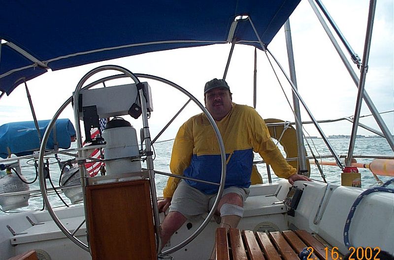
Thought I'd throw in a couple pix that I took on the American Eagle out of Rocklin, Maine. Though these are not mizzen masts the issue is the same: how to keep it from falling into the cockpit when the sail is down. These two pix employ the topping lift solution.
-
modlerbob reacted to Julie Mo in Endeavour 1934 by Julie Mo - Amati - Scale 1:35 - America's Cup UK J-Class Challenger
I got all the mahogany strips for the keel glued in place and smoothed. It turned out okay.
Then came the lacquer, mostly to protect the bare wood from contaminants.
I took the hull outside to spray the lacquer. With the house closed up, the lacquer smell permeates every room, even with the shop door closed. So the hull got a little sun today.
After I get the deck glued down, I'll trim the planks flush.
On a sad note, when I was gluing the keel strips in place, I used rubber bands around the hull. At one point I placed the stern on the floor to put some rubber bands on at the bow. The bow was leaning on my knee with the keep in the air. The weight of the keel spun it around and I heard a sickening CRUNCH! I looked at the stern and about half of the planks on the transom broke off below the rail line. Two steps forward, one step back...
-
modlerbob reacted to popeye the sailor in The Jolly Roger by popeye the sailor - Lindberg - 1:130 - PLASTIC
I did two more sails yesterday......lashing the yards on.....and I had a better time of it. knowing when to avert problems is a big help the lower fore sail assembly is already done, so the two additional sail assemblies, complete the fore mast. I quickly looked up the names of these sails to make it easier.......I may be wrong.....so be kind and let me know so.....anyway...before I knew it, I had the fore course and the top sail cemented in place.
I rigged the fore course sail lifts before adding the top sail......the lifts for that sail was next.
the sheet/clew lines are not done yet, so not to make it too confusing. the top sail.......for this large a sail, I probably should have given it a pulley assembly......but I opted to use single blocks instead. the fore course sail got the pulley assembly.
the top gallant sail was the last assembly to be cemented in place.
I'm thinking that this would be a fixed yard, so no lifts would be needed.....simple fixed lift lines was added to it. I will have to do the same to the main top gallant sail, but I had to remove the single block that were tied to the yard.
once all of the lift lines were rigged, they were set up to be terminated. once that's done, I can rig the sheet/clew lines.
one thing I see, that I will have to remember to do, is rig the tack lines on the fore course, before the sheet/clew lines are done. three more sails to go......the main set. it might appear that I've added a lot of the rigging......actually.....no. this model has most of these lines.......I'm merely doing it differently, adding in some extra detail due to the use of these blocks.