EdT
-
Posts
2,214 -
Joined
-
Last visited
Content Type
Profiles
Forums
Gallery
Events
Everything posted by EdT
-
Lovely work, Maury and thanks for the plug. But..... one 's' in Plexiglas please. (Still guarding the trademark like a good former employee.) Ed
- 525 replies
-
- 3
-

-
- anchor hoy
- hoy
- (and 1 more)
-
Bravo, Nils! Really coming together nicely. I love the deck machinery. Ed
- 2,625 replies
-
- 3
-
-
- kaiser wilhelm der grosse
- passenger steamer
- (and 1 more)
-
Beautiful work, Druxey. My vote would be for the blades to be vertical, but this does not show off the lovely blade decoration as well as the horizontal arrangement. I am always puzzled by the length of these sweeps because the mechanical advantage for the rower is really minimized - requiring much more force on each stroke - to say nothing of traffic problems. Of course shorter oars would require more strokes. Was there a reason? Ed
- 641 replies
-
- 5
-
-
- greenwich hospital
- barge
- (and 1 more)
-
Magnificent,Johann.
-
Very good comments on precision and scale, Micheal. Thanks for giving me an excuse to continue with the subject. You are quite right and I agree that 1/8 at 1:72 scale - an actual .0017" - has little meaning on the model - a mere swipe of sandpaper or two. When one considers that the original offsets table was created by taking physical measurements from a 1:48 scale half hull model where 1/8" = .0026", the idea of this precision becomes even foggier. Considering that even in the presence of measurement error from the 1:48 model to the offsets table, shipwrights still lofted patterns using these table dimensions. So, we can take some confidence that the table is fairly representative of the constructed ship. From the modeler's perspective, precise drawings based on the table can - in a way - be considered to have "zero" ( i.e. < .0017") error, since the precision of the CAD drawing is set at 1/8" real world. (When drawing a part - say a deadeye - and displaying it at say half the size of the screen, a 1/8" (actual) change in a dimension is easily detectable.) With this in mind the modeler can proceed confidently with construction, comfortable that the drawings and patterns do not already contain an accumulation of error from measurements, tracing, setting out, pencil width, and the like. This accumulation of error - when added to construction error - can have noticeable effects. I have seen this evidenced at various times in postings on this site as modelers wrestle with the issue - to say nothing of the accepted practice of heavy sanding/paring to fair hull framing. Don't get me wrong. I would not for a moment represent that my modeling achieves anything like this high level of precision, nor would I suggest that anyone set such a standard as a goal. However, it is of comfort to me that I have only to deal with my own modeling error and not error built into the drawings. So, to me, that is the value of all this. I can accept the drawings and deal with or accept my own inability to duplicate them in wood. The other value of this somewhat arcane but useful discussion is that understanding error and precision can only be helpful in improving one's work. In reading all the above comments, I trust everyone recognizes the distinction between the concept of error and the entirely separate issue of drawing mistakes. If not, I will be happy to try and explain. Comments welcome! Ed Almost forgot, Micheal. On the 6" deadeyes, the largest source of drilling error: flexing of the drill bit. The only remedy: keeping the bit projection very short.
- 3,618 replies
-
- 15
-
-
- young america
- clipper
- (and 1 more)
-
Brilliant. The process development work you have done is extraordinary in itself, even without the end product model that I am sure will be amazing. Ed
- 281 replies
-
- 3
-
-
- falls of clyde
- tanker
- (and 2 more)
-
Thank you for this note, Bob. Using the approach described I became fully confident in the ability to bevel frames completely before erection, leaving only final finish sanding necessary on the framed hull. I trust you will have the same experience with your frames. The primary enabler for this and for the pin-indexed frame fabrication process is, as I am sure you realize, the precision of the pin placements on partner frames and also the precision of the three profiles drafted on the patterns for each frame pair. This is my best example of a holistic modeling process that begins with drafting methods specifically tailored to support the modeling steps. In his build log for the Irish famine ship, Frank (mahuna) adopted (and enhanced) this method of drafting and is using it in his framing as another example - an excellent one at that. The key to this method is CAD drafting technology, and specifically the use of it's precision in taking and setting measurements. While CAD can certainly be used to trace over imported images, this is much like using a Ferrari to do grocery shopping. This method has error implications that may be more or less serious, depending on the modelers expectations for accuracy. In the case of Young America, the original builder's table of offsets (accurate to 1/8" actual) was used to precisely draw waterlines. With the fore and aft edges of every frame drawn over this plan, the precise dimension to every point on every profile could be measured and transferred to a body plan view to accurately draw each required profile. Duplicate pin placement on paired frames was an easy next step. Having an original table of offsets is not a prerequisite to use this method. Rather than tracing frame profiles or even half-breadth lines from an imported image, measurements of waterlines and ribband lines can be taken from the print and used to create a derived table of offsets. These dimensions can then be used as described above to create a half breadth plan for the model. This method requires fairness checking of the half breadth plan to account for potential manual measurement errors and/or distortion in the print used. This can be done by inspection of the half-breadth lines themselves and by drafting and checking some representative frame profiles from this plan. When the half breadth lines have been checked to satisfaction, the dimension capabilities of CAD can be used to take and set profile dimensions. Using snap-to-intersection capability and keying in of dimensions to set points assures precision. Some will say, "Is all this precision necessary?" The answer is, of course, no. While, it is true that imprecision in drafting model plans can lead to construction problems, nth degree precision is not needed to avoid that. Each modeler's goals are different - as they should be. Not everyone is bitten by the structural precision bug. If you are, the above comments may prove helpful. Ed
- 3,618 replies
-
- 17
-
-
- young america
- clipper
- (and 1 more)
-
Thanks, everyone. Druxey, I think you are right about the wax. Its almost too simple a solution, especially for one (me) who uses wax finish on virtually everything else. I've been staying away from the wax solution since reaching the open decks because there are still lots of glued attachments to make, but the deadeyes could clearly be waxed without compromising that - probably applied after blackening the deadeye/chain assembly and before installing - will give it some thought. Thanks. Ed.
- 3,618 replies
-
- 8
-
-
- young america
- clipper
- (and 1 more)
-
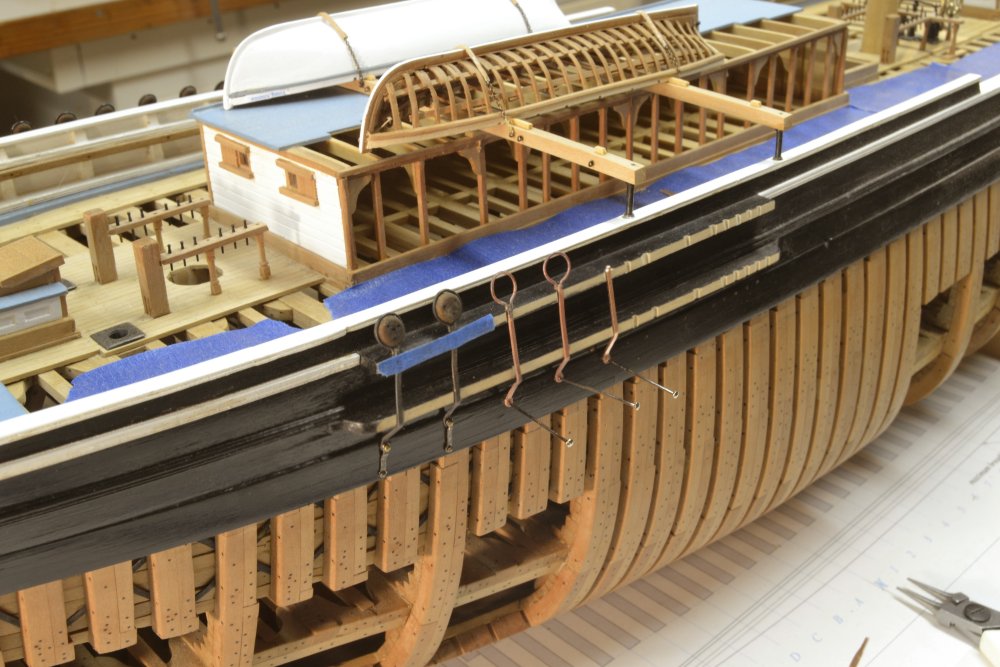
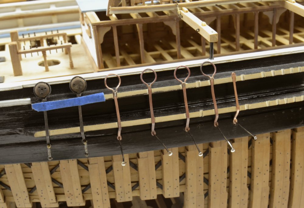
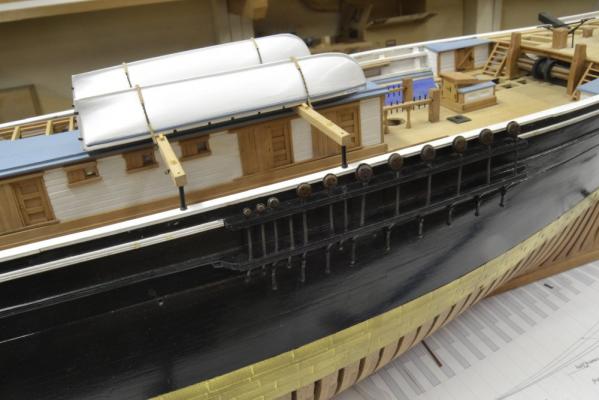
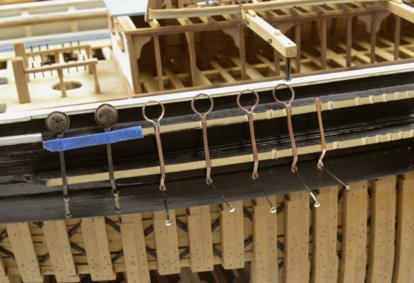
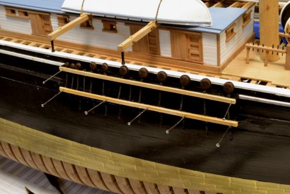
Young America - extreme clipper 1853 Part 160 –Deadeye Chains continued Making the channel deadeyes went like lightning compared to making and installing the chains, but finally the fore and main channels on the starboard side were completed. The first picture shows the fore starboard channels after painting the cap rails. The completed main channel on the same side is shown below. The photo highlights the need for some more liver of sulfur on some of the chains. The deadeyes in all these pictures show very little luster – less than I would like. Repeated doses of Tung oil and buffing have left them flat and lifeless. Obviously all of the oil has been sucked into the end grain faces of the deadeyes. To remedy this I am now treating them over the oil coats with my old wood finishing standby, Wipe-on polyurethane. I have also learned that all this finishing needs to be completed before fitting the deadeyes to the straps – unless they are perfectly aligned beforehand – not impossible but difficult. In trying to rotate one after some post-application of oil, I broke the strap joint. You may recall in the last post that I sized the slots in the channels to pass the lower eyes of the chains in case this happened and one had to be replaced. That was a good idea. The next pictures show work on the fore port channels. In the first picture the first two deadeye/chain/chain cleat assemblies are installed and a shaped piece for the third is being fitted for cutting off. In the next picture it has been cut to size and the top end crimped for the strap joint. The size is being rechecked before fitting the strap. Work continues in the next picture. The fit on these is again checked after soldering the straps. The next picture shows all six shroud chains fitted – minus deadeyes and blacking at this point.. This picture shows the next (7th) chain. This simply has an eye at the top to take the standing end of the fore upper topsail halyard. As a side note, I must say that taking these pictures and writing the text for this blog is often very helpful in finding and avoiding mistakes. In the above picture you will notice notches cut into the channels between the 5th and 6th shroud chains, supposedly for the halyard standing end chain. Seeing this located in that position in an earlier photo - when writing its caption - caused me to wonder about that location which indeed turned out to be incorrect – a drafting error. The incorrect placement of the chain for line 240 can be seen in the first photo of the previous post (159). The drawing was corrected and the chain was relocated as shown above, aft of the shrouds where it will be free of interference. The companion chain for the halyard tackle on the other side also had to be removed and relocated – again making use of the increased slot width described above. There is still quite a bit of this work to do and it is going slowly as I am diverted by the usual list of springtime chores. Ed
- 3,618 replies
-
- 39
-
-
- young america
- clipper
- (and 1 more)
-
Good to see you back, Bruce. Look forward to the pics. In their attempt to make it easier to use, Microsoft has succeeded in making navigation through the file directories almost impossible. My sympathies. Who files all their documents - or pictures - in one place?? Ed
-
I like your fixture, Druxey, if you have just a few sizes - and if you reuse it on succeeding models. Young America has virtually every size from 16" down to 6" diameter, so I guess that would mean several different fixtures, right? I have used two methods. On the larger deadeyes a smaller diameter dowel in the chuck to act as a platform for the deadeye, shown in a previous post. And then there is the tape that works quite well on all sizes. In both cases the drill can pass out through the lower face. I assume the drill bottoms on the cup in your fixture. I assume the fixture also serves as a good holder for final sanding/buffing? Ed
- 3,618 replies
-
- 6
-
-
- young america
- clipper
- (and 1 more)
-
They look pretty clean to me, Glenn. Dust in photos is a major nuisance. Even when all looks clean, dust shows up, especially in closeups. I'm glad I'm not buying film anymore. I could not afford the retakes. Ed
-
Thanks for the comments and likes, everyone. Mark, the masking tape turned out to be the savior of my sanity. Paul, the channels are glued to the frames and bolted through - like the originals. They need to be strong. Filing is a bit awkward but needs to be done after installation on double channels to get the right angles for the chains. Ed
- 3,618 replies
-
- 6
-
-
- young america
- clipper
- (and 1 more)
-
Very nice to hear from you, Robin. I trust all is well. You may paint my model whenever you wish. Ed
- 3,618 replies
-
- 11
-
-
- young america
- clipper
- (and 1 more)
-
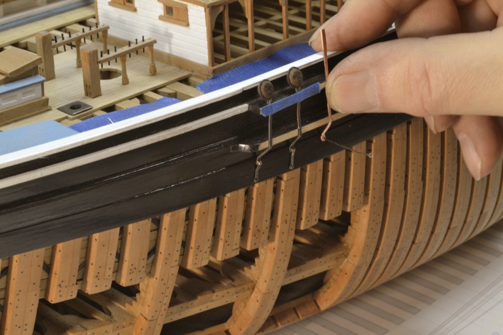
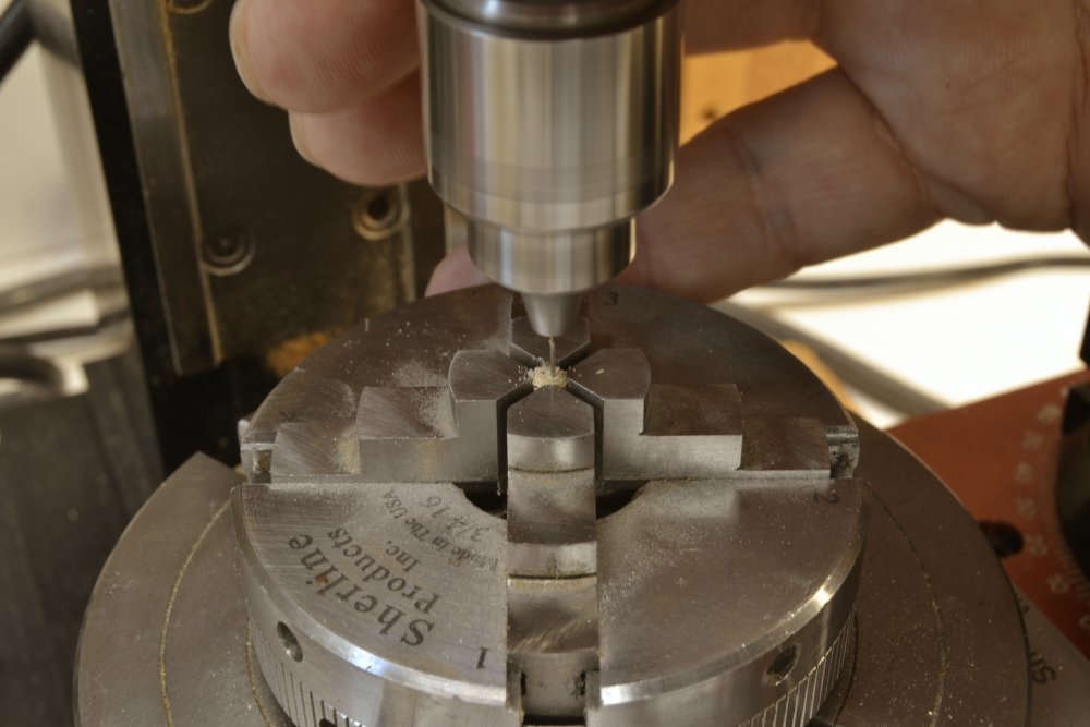
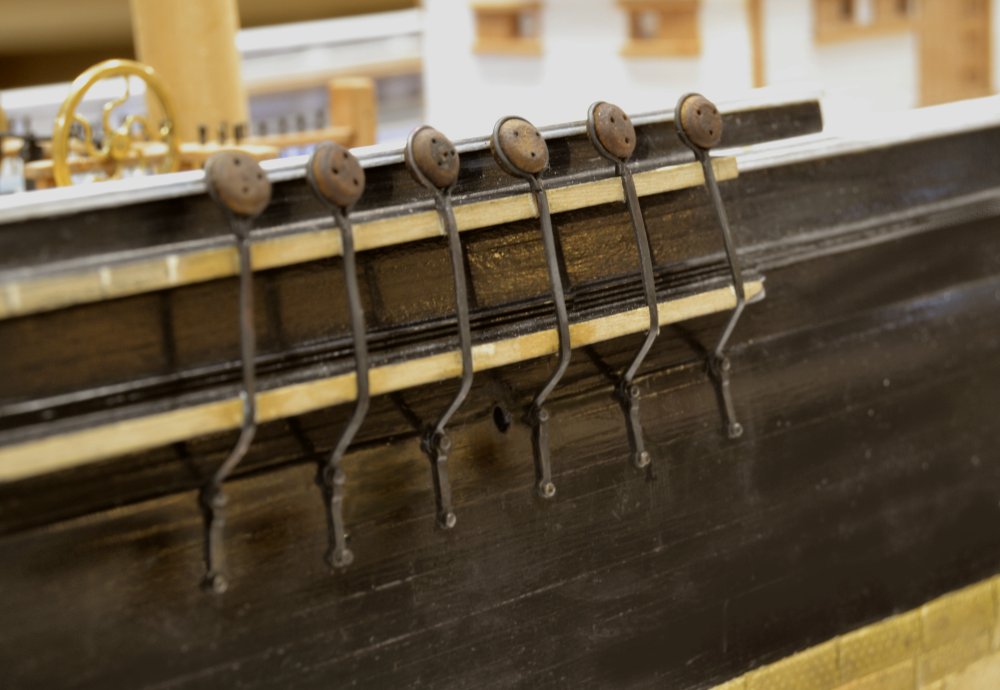
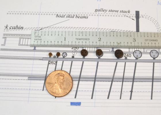
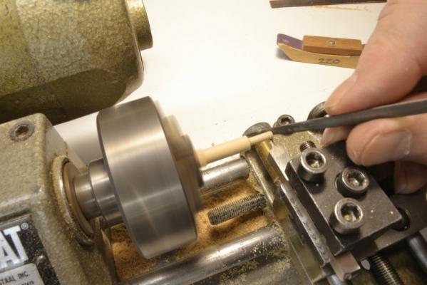
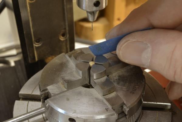
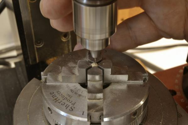
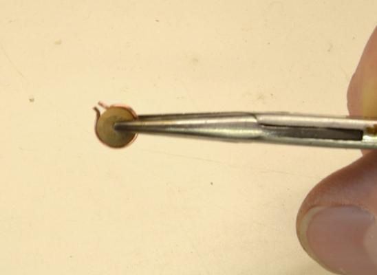
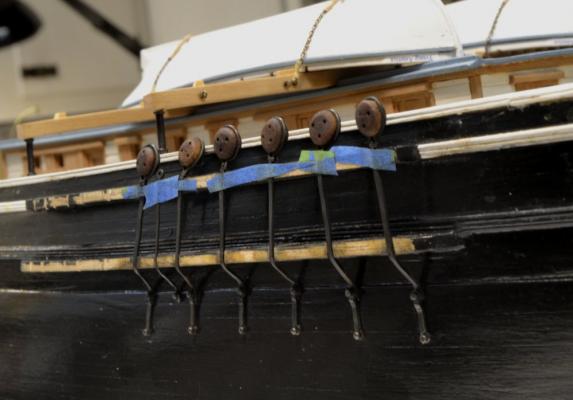
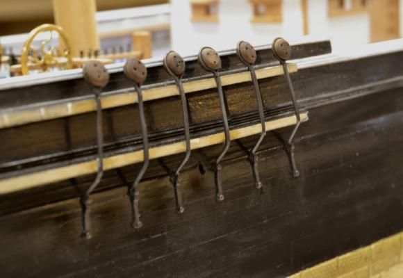
Young America - extreme clipper 1853 Part 159 –Deadeye Chains continued Work on the chains and deadeyes has been slow going, but I have a few progress pics to post. After making the large 16” deadeyes for the lower shrouds and fitting some of them to the channels, I turned to the smallest size – the 6” deadeyes for the skysail mast backstays. I then started working back upward in size. The fist picture shows some of the smaller deadeyes, placed in position on a drawing of the starboard fore channel. When this was taken, I had not yet made the 9” deadeyes for the fore and main topgallant backstays, but the other sizes are shown. The drawing is incomplete – note the missing chain plate cleats at the foot of the chains. The numbers on the drawing are line numbers from the rigging list. I used a slightly modified process in making the small diameter deadeyes. The next picture shows the rounding of a 9” deadeye in the lathe using a barrette file. I used a shaped cutter for the 16" and 13" sizes. After this step the deadeye was parted off as with the larger sizes. The next picture shows the set up for drilling all the deadeyes. After dropping a few of these down into the chuck while trying to align them in the jaws, I resorted to the blue masking tape in the picture to place the deadeye and hold it while tightening the jaws. This worked perfectly and is a good solution for those of us with shaky hands. The next picture shows drilling. The holes are approximately 10% larger than the specified lanyard diameter. The next picture shows the fore starboard channel with all the chains and deadeyes fitted and the capping rails pinned in place. The last picture shows the slots for the chains on the port fore channels being filed out. Before this step, the positions of the slots for each line on each channel was marked using a string from the appropriate height on the dummy foremast that can be seen in this picture. A common slot size was used even though some of the chains are smaller. This was done to allow the eyes on the lower ends to pass through the slot if a replacement is necessary later. Since the soldered joints take rigging stresses, this is a distinct possibility given the large number of soldered joints. Best to be prepared. Ed

- 3,618 replies
-
- 45
-
-
- young america
- clipper
- (and 1 more)
-
Lovely work, Druxey. Any special paper on the friezes? Ed
- 641 replies
-
- 3
-
-
- greenwich hospital
- barge
- (and 1 more)
-
Thanks again for the comments and likes. Rob, the fit of the straps lets the deadeyes turn but not freely. They are fairly tight - just large enough to snap the deadeye in. It akes a few to get the forming of the strap to the right size. Ed
- 3,618 replies
-
- 5
-
-
- young america
- clipper
- (and 1 more)
-
Thanks everyone. The copper phosphorus solder melts at 1325 degrees. Here is a link to my source: https://contenti.com/jewelry-soldering-supplies/solder/phos-copper-solder-paste Ed
- 3,618 replies
-
- 7
-
-
- young america
- clipper
- (and 1 more)
-
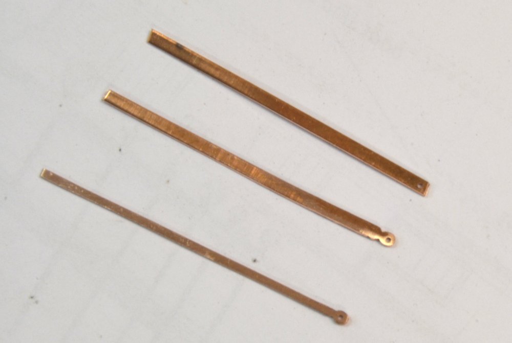
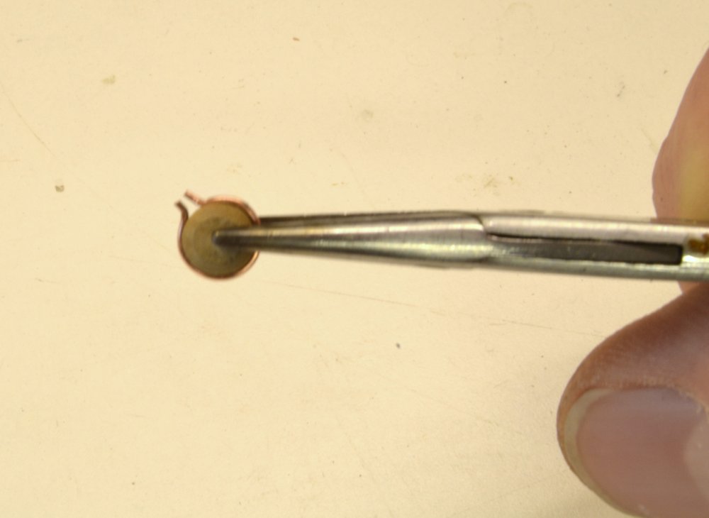
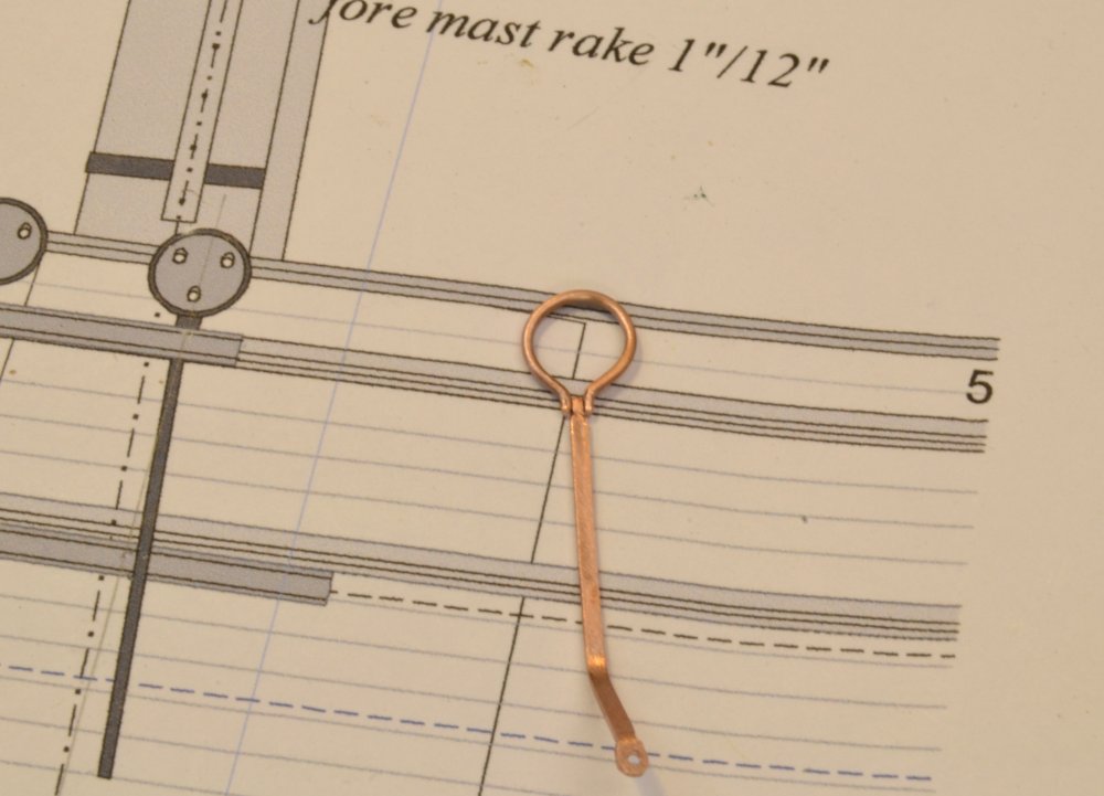
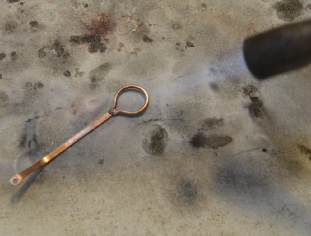
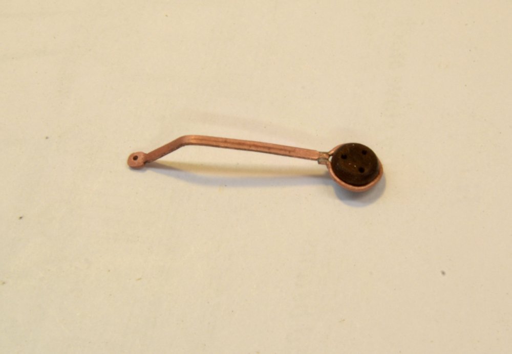
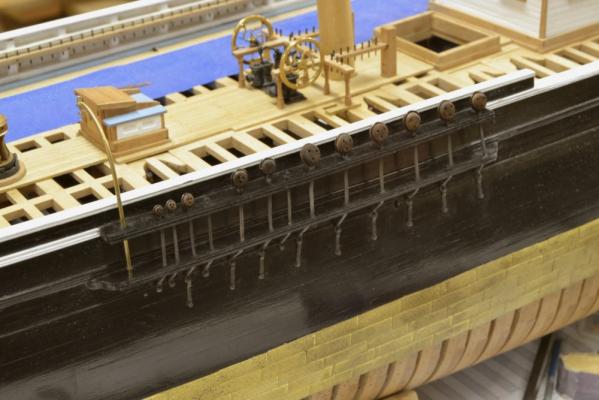
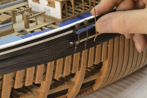
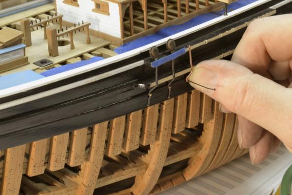
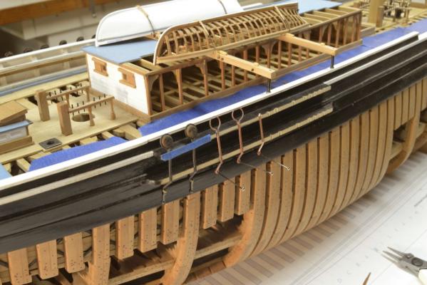
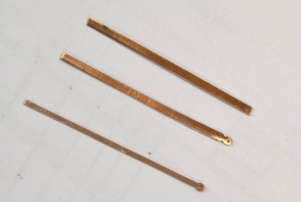
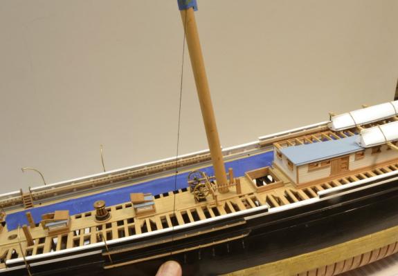
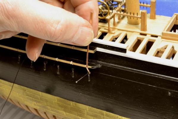
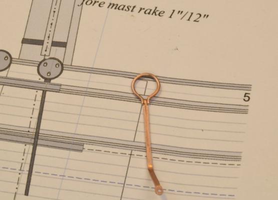
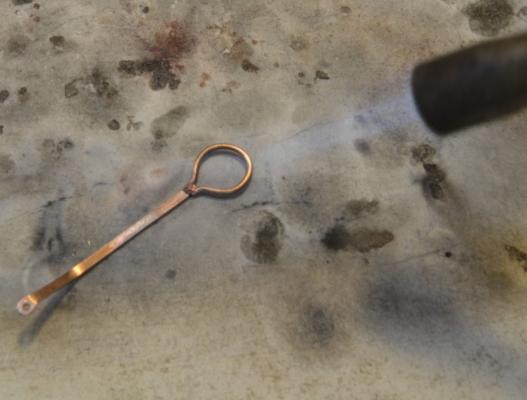
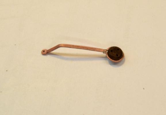
Young America - extreme clipper 1853 Part 158 –Deadeye Chain Plates The deadeye chains (aka chain plates) on ships of this period were iron bar forged at each end with holes to take bolts. I made these about 1” thick and 2 ½” in width, certainly stronger than the 11” shrouds. These could have been made by the method used in the last post for the backing plates, namely by soldering tube at the end of a plate then slicing them off. This would involve a lot of metal sawing and a lot of material wastage on these long pieces. Also since the lower ends of these are bolted under the backing plates the rounding of the bolt eye need not be absolutely perfect. The first picture shows the progression followed in forming these after the copper strips were cut to approximate width. I used a paper cutter to cut the strips then straightened out the curls by stretching the strips in a vise as was done many months ago with the iron hull strapping. Pulling these also hardens them, though that hardness is soon lost when they are annealed under the soldering torch. The strip at the top has been drilled for the lower bolt. In the center piece the lower eye has been roughly shaped. At the bottom is the finished piece with its width reduced to the 2 ½” (.035” actual). Before these parts could be sized and assembled with the deadeyes, the length of each chain had to be determined. The next picture shows the positions of the chains on both starboard main channels being set out with the aid of a string taped at the height of the top on a dummy main mast. Notches for the chain plates were then filed out and each plate fitted as shown in the next picture. On this channel I set the backing links first, then pinned the chain plate at the bottom, bent the angle at the lower channel as shown. The top edge of the top channel was then marked on the plate, the plate removed and then trimmed to size. The top of each of these was then crimped with pliers to make flat fore and aft surfaces to seat the iron deadeye straps. In the next picture one of these straps has been formed around a 16” shroud deadeye. The copper wire was wrapped around then crimped at the bottom. The ends were then filed off square and then flattened with pliers. On the ship these were bolted through the tops of the chain plates just above the channel. I entertained the idea of bolting these until confronted with the small size – too small to drill – at least for me. The next picture shows a strap and chain plate assembly after forming the chain at its position on the fore channel and before silver soldering the pieces together. The next picture shows the pieces being soldered using a small propane torch. Copper phosphorus solder was used because it blackens well with the liver of sulfur that I use to blacken the copper. After soldering, these were dropped into a Sparex® solution. After rinsing the deadeyes were fitted into the ring as shown in the next picture. This entire assembly was then dipped in liver of sulfur solution to blacken the copper. The next picture shows the fore channel with the lower shroud deadeyes installed. These are bolted (nailed) into the 6” thick wale planking with the top bolts in the uppermost wale strake. All the chains are shown being restrained from unruly behavior by bits of masking tape. The smaller chain plate forward of the last shroud chain will anchor the eyebolt for the standing end of the upper topsail halyard. This lighter duty chain has no backing plate and was made from 20-gauge copper wire flattened a bit. I may replace this with a rectangular bar – like the others but smaller. The channel capping rails will be added after the remaining chains for other rigging are fitted. When that is done all the chain plates will be straightened. At present the soft annealed copper on these is a bit deformed from handling. The deadeyes will be aligned neatly at the top later when the ship is rigged. The last picture shows the main channel after fitting of the six lower shroud chains. Ed
- 3,618 replies
-
- 47
-
-
- young america
- clipper
- (and 1 more)
-
Sweet work, Frank. I like the method for the chocks. They were quite small. I noticed that in an earlier post showing the drawing. I presume their purpose was to hold the frame together until the sister frame was bolted, but I am not sure about that. At that length they could not have provided very much strength. I continue to be fascinated and envious of your meticulous and precise approach. Bravo. Forgot to mention - the full descriptions and the photography are great. Ed
- 649 replies
-
- 7
-
-
- dunbrody
- famine ship
- (and 2 more)
-
Thank you all - for comments and likes. This method of making the plates - they seem to have a variety of names: chain preventer plates, chainplate cleats, backing plates, etc. - has advantages and disadvantages. First, a very good silver-soldered joint between the tubes and the plate is most essential to keep the tube ends from breaking off when bent. Sawing the plates puts a lot of stress on those joints as well. There is still quite a bit of filing involved but at least that is all on a flat surface and does not require the rounding of the ends. Also, tube sizes are limited so having the right size is a prerequisite. I am now making the chainplates - or if you prefer, chains. These are being made from strips of copper cut from a sheet - then drilled, the ends filed round and then filed to width. Take your pick on the method - each has pluses and minuses. will have some pics of the chainplates soon. Ed
- 3,618 replies
-
- 10
-
-
- young america
- clipper
- (and 1 more)
-
Excellent description of the method, Frank. The care you are taking with marking the center lines for drilling will pay off. Its really the key to the process. You are obviously taking meticulous care that I am sure will pay off in a beautiful result. Out of curiosity, is there a reason for orienting the mill vise with the tightening screw to the back? I normally have the screw at the front for better access and to avoid it fouling the vertical post. There are aspects of this vise that can be annoying. Any little secret you may have have found would be of interest. thanks. Ed
- 649 replies
-
- 6
-
-
- dunbrody
- famine ship
- (and 2 more)
-
Cannons look great, Jerry. The enclosed Unimat motor does run hot as do most non-ventilated motors, but most are designed for that. If you can put your hand on it, its probably OK. As I noted earlier, mine does occasionally pop the GF circuit. Liver of sulfur works great on copper but regrettably has little effect on brass. The three-jaw Unimat lathe chuck is convenient but does not hold as well as the independent four jaw chuck. That chuck takes some getting used to, but I prefer it for most work, especially when a tight grip is needed. With the three-jaw, you have to watch the feed rates and spindle speeds to avoid the problem you described. Ed
-
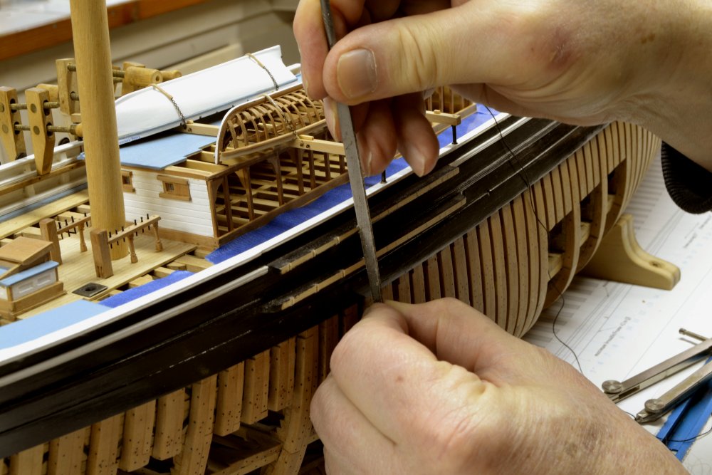
Wonderful photos. I look forward to your modeling of this. These and Nils,s work are whetting my appetite to build a steam ship. Ed