Charter33
-
Posts
455 -
Joined
-
Last visited
Content Type
Profiles
Forums
Gallery
Events
Everything posted by Charter33
-
Thanks O.C - I'll have a go tomorrow when I get another chance to play on the Admiral's pc..... Graham.
-
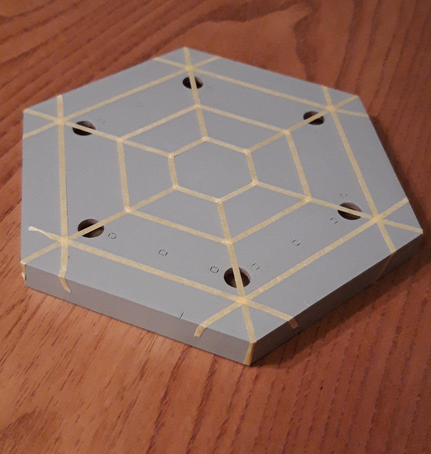
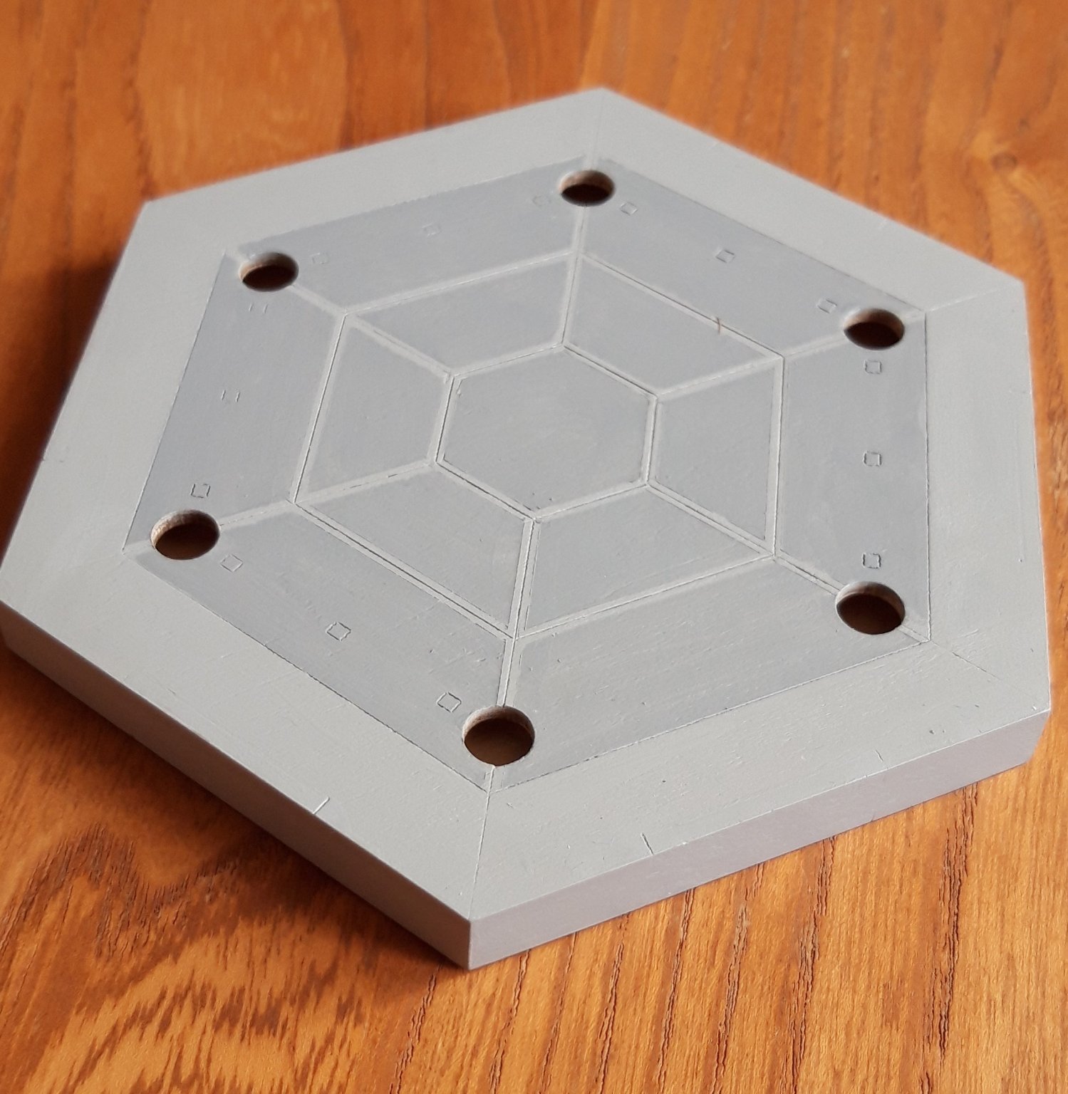
I have had an interest in Chinese architecture for many years, so when I came across James H's review of this kit I was keen to explore it further. The kit itself looked excellent value, but the cost of shipping was a bit of a surprise! When my two sons asked for suggestions for a suitable gift for Christmas this the one item at the top of the list. I came across a similar pavilion in Hong Kong several years ago .... and often see an even more similar structure at RHS Wisley in the UK, although not as ornate as the kit, with a different style top decoration and one of the seats missing to enable visitors to pass through ..... (not my own picture) Well, Christmas arrived, all be it very low key and unusually quiet, and I was the proud recipient of a plain brown package with an intriguing colour photograph of a pavilion on it. The decision was made to attempt a fully painted model. It took the best part of an evening armed with a sharp scalpel and cutting mat to carefully cut out all the separate components and bag them up. The quality of the laser cutting is exceptional, with many of the decorative pieces finely detailed but, be warned, some are very fragile. First bit of advice - hang on to all the off-cuts of ply, they will prove to be very useful! Thanks to James's detailed review the construction of the base, and the construction up to the roof should be straight forward. The instructions are graphically nicely clear, but my knowledge of Chinese is limited to introducing myself and saying thank you - reading the written instructions is beyond me. The CAF website, fortunately, has a very helpful gallery of pictures showing both the finished model and the real thing. These were a regularly visited resource during the build. First step is to construct the hexagonal base. This went well, following the advice to cut the bevels on the ends of the side pieces with a scalpel. Unfortunately I forgot to photograph this stage! I decided that this base needed painting before progressing further. I started by hand brushing a light grey across it all surfaces. I then used 2 mm Tamiya masking tape to mask the grout lines that are evident in the gallery pictures. I then darkened some of this shade of paint and went over the inner panels: Photo attachment problem seems to be sorted! Graham

.jpg.53398089a003a9a7ff0ab8bf54c1d076.jpg)


-
Outstanding, and truly inspirational work as ever, Robert. Thank you for sharing the link about the bucket decals - that's definitely a route I shall be persuing! My own build continues well, but a little more slowly than yours. I have had to retire from a lifetime of teaching and one consequence has been the loss of access to a computer and subsequently my ability to add posts to my own build log. I can only visit this website using my phone which is hampering my contributions, especially with a fault that appeared after the most recent up-grade that causes the phone's operating system to crash after every 'up-swipe' - it gets very frustrating when the screen only advances a couple of lines before locking up, to put it politely ....(it's taken over half an hour to add this post!!!!🤨) Keep up the excellent work! Graham.
-
Guy, You might like to have a look at the adjustable height benches made by Emir. They call their range 'Varihi'. They come in a variety of styles including traditional square beech frames or steel tubing, and are adjusted with a mechanism they descibe as a hydraulic crank. When the school I taught at refurbished our five workshops we had some of these installed in every room to support students with a wide range of disabilities and needs. They are of good quality and proved to be a very successful solution. Graham.
-
Blackening brass
Charter33 replied to Bill Hill's topic in Painting, finishing and weathering products and techniques
Hi Bill, I was advised to use Birchwood Casey Brass Black by other members of this web-site and have found it an ideal product, although the initial preparation of the brass is a crucial factor in achieving the optimum result. Cheers, Graham. -
Hi Nicholas, It's a while since I have been able to get near by own build of the Triton, but from memory I think you will find that these rectangles show the position of the scarf joints that join the various pieces. If you look at the central one on the plan view labelled 4 (keel) the view shows the type of joint from the side. The rectangles on 1 and 5 (keelson and false keel) are the same joint but viewed from above. The aim is to have the orientation of the joints on each separate assembly alternating for additional strength. The same joints appear on the side view but the other way round. Hope this makes sense! Good luck with your build - I look forward to watching your progress. Cheers, Graham
-
Hi David, I posted a reply to your enquiry last night - I had missed your question due to work, sorry for the delay in getting back to you. It's at the end of my build log. Graham
-
Hi David, This is only my second attempt to build a model ship so I wouldn't regard myself as being anywhere close to being an expert! I tend to 'wing it' and rely heavily on the build logs of the more highly accomplished members of this site and my copy of 'The New Period ship Handbook' by Keith Julier. I'm happy to try to answer your questions as best I can: 1. Follow the instructions to fit the dummy barrel strips. They get painted black before the gun ports are glued in place. Eventually, once the hull is planked and the ports have been lined, holes are drilled into the dummy barrel strip to take the pins on the back of the dummy cannons. If you go back though my build log you'll see how I used a rectangular block of wood that fitted snugly into each port and rests against the strip as a guide for a Dremel drill. There is plenty of room as you are only gluing in shortened cannon muzzle ie. there is no carriage etc. to worry about. 2. The lining of these ports was a concern I had too but it turned out to be very straight forward. Each piece of lining is carefully cut to fit firmly in the gap and is glued in place butting onto the edge of the gun port pattern. I think I glued the bottom and top horizontal pieces in first, and once these had fully dried added the side pieces. They proved to be fine in terms of strength once the glue had set. There is a very clear description of how to do this in the book I mentioned (P.31) 3. I'm a little confused with this one - I've just checked my hull and there is no need for any deck as, once again the dummy cannons glue into holes in the dummy barrel strip here, although these holes do appear to be much closer to the top of the strip that further forward along the hull. Hope this goes some way towards resolving your concerns. I look forward to seeing how you get on and hope you will be starting a diary of your build too - it's a great and valuable way to get feedback and support from the community here. Good luck, Graham.
-
Stunning work and attention to detail, an inspiration as always! Graham.
- 527 replies
-
- 1
-

-
- caldercraft
- victory
- (and 1 more)
-
Yes - that's the one, Bruce. It was 'donated' to me by the father of one of my former students when he up-graded to a larger machine. The electricity company did their work at the beginning of the summer break. It only took a few days. They then left the trench work open for the next month. I got away with some light surface rust that was easily dealt with. A couple of bearings had to be replaced anyway and I also took the opportunity to replace the 3 jaw chuck. Bought a nice but inexpensive 4 jaw independent at the same time. It was left to dry out for a very long time before connecting it to the mains supply! Cheers, Graham
-
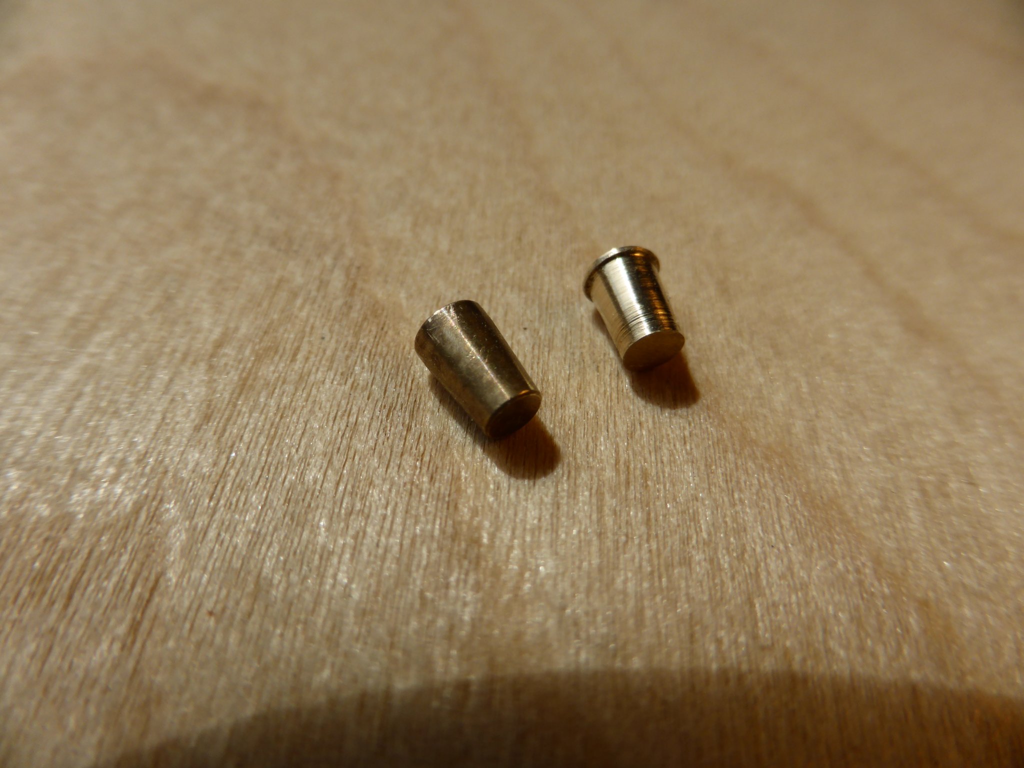
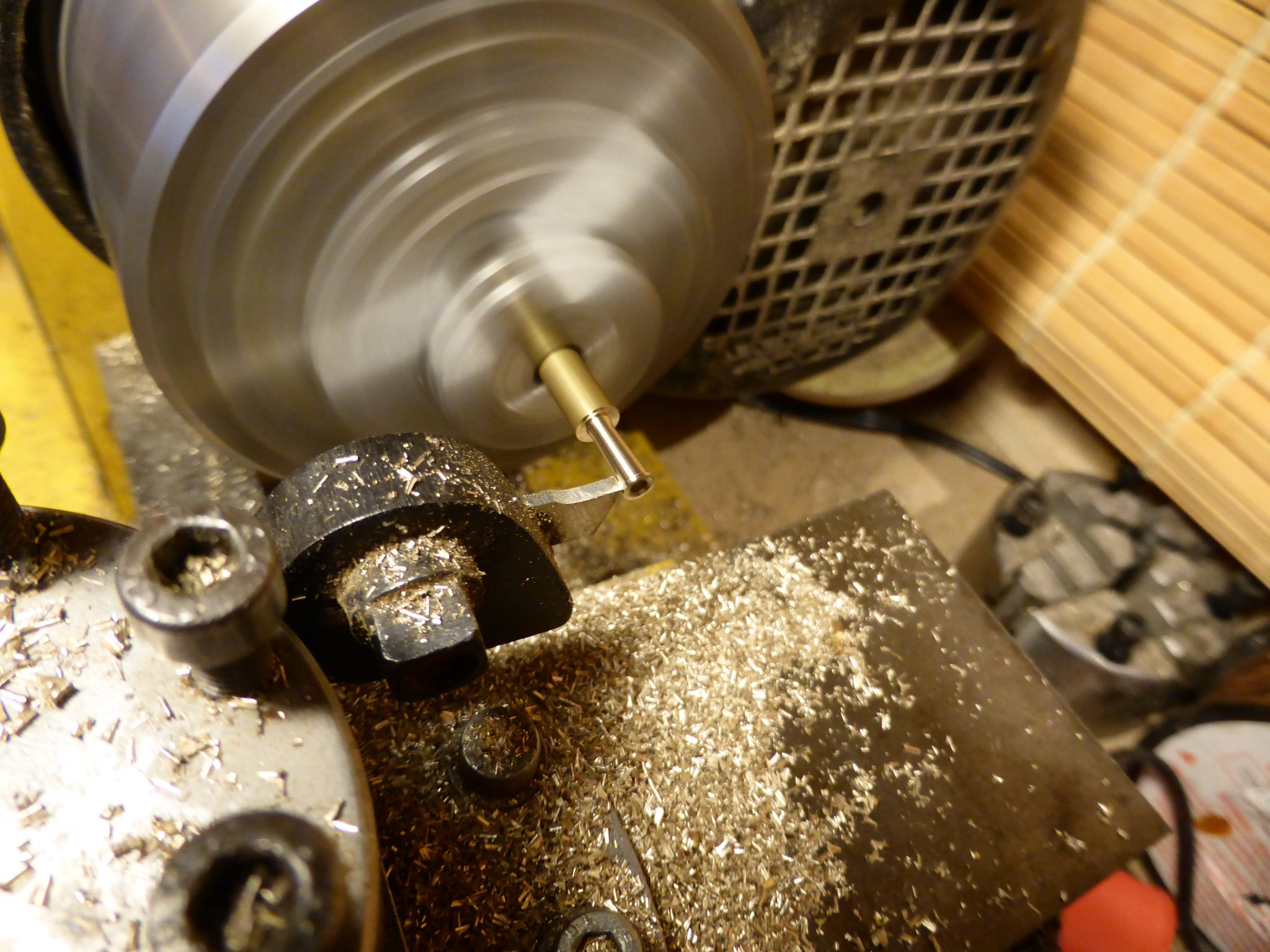
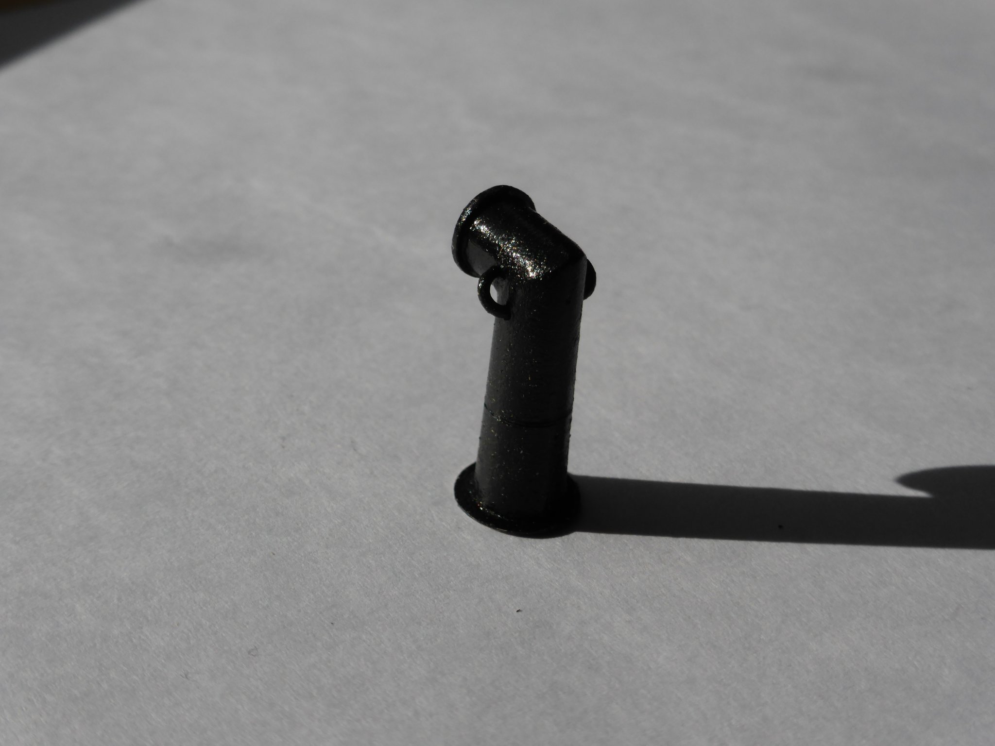
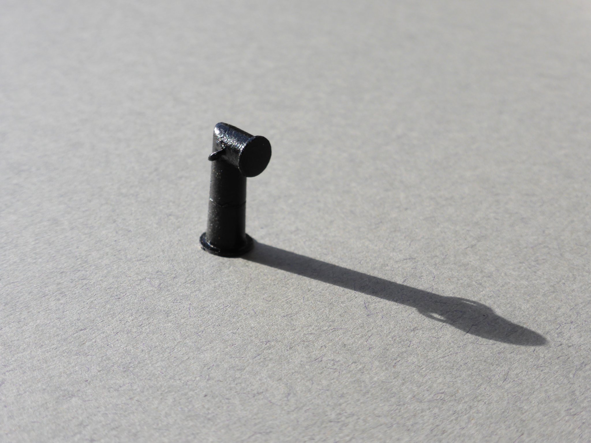
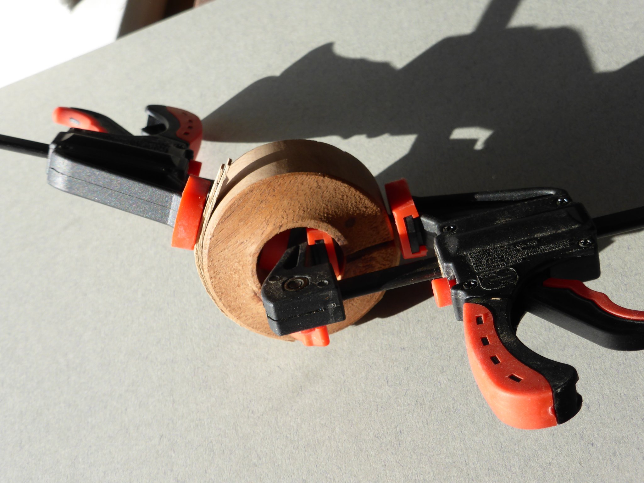
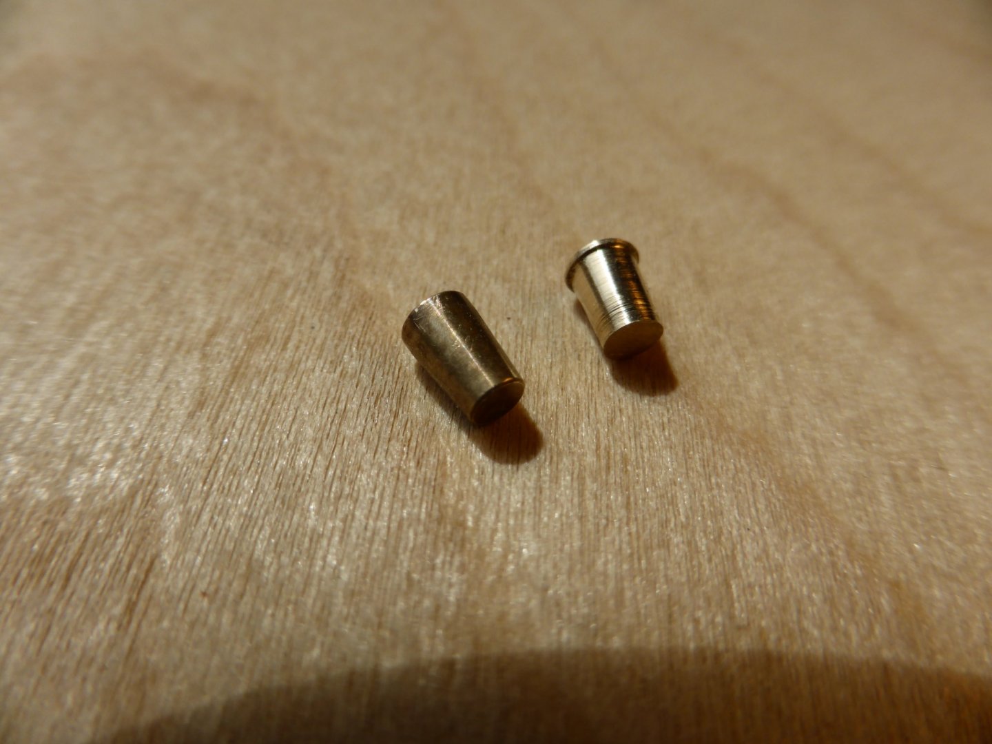
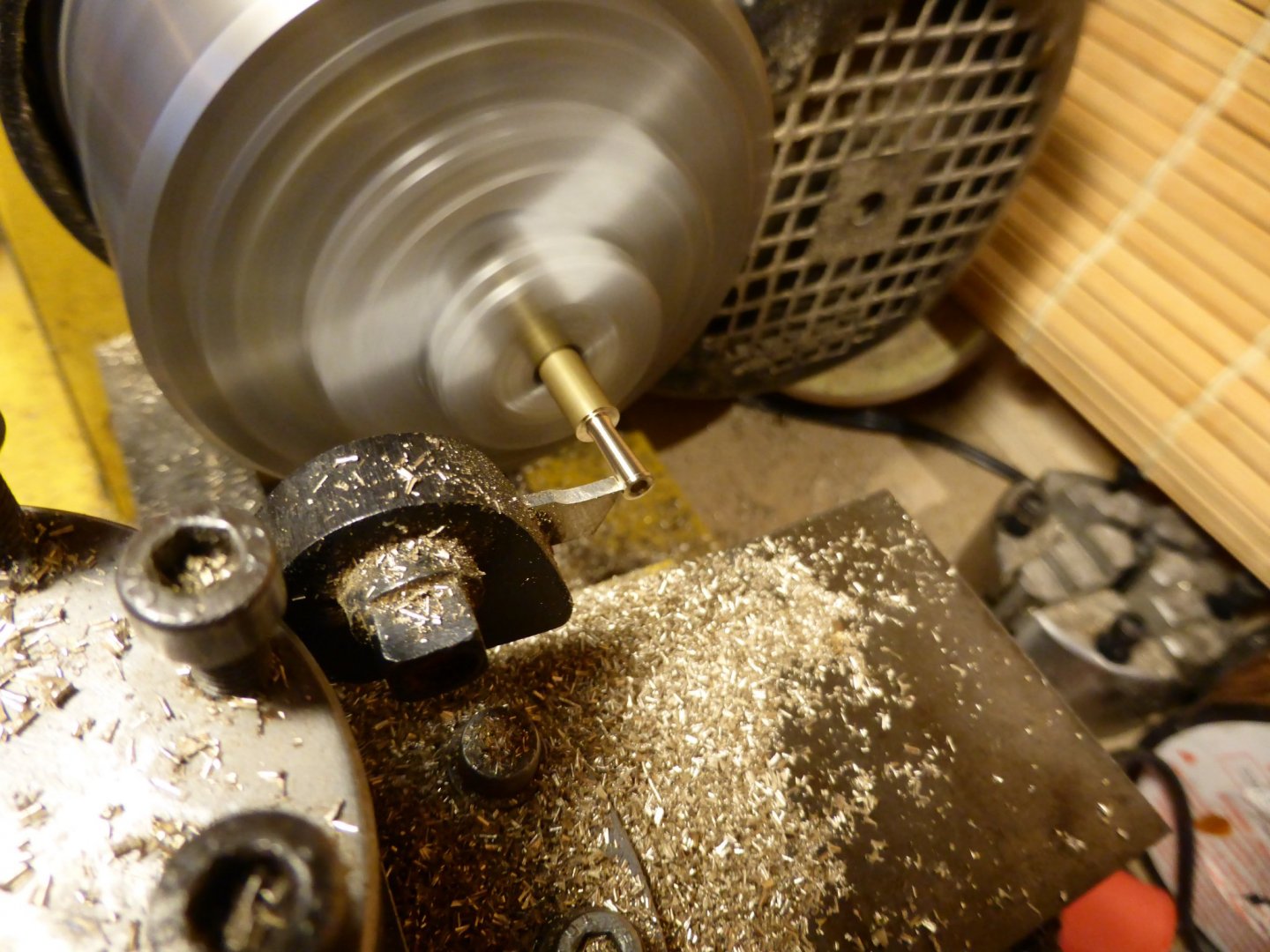
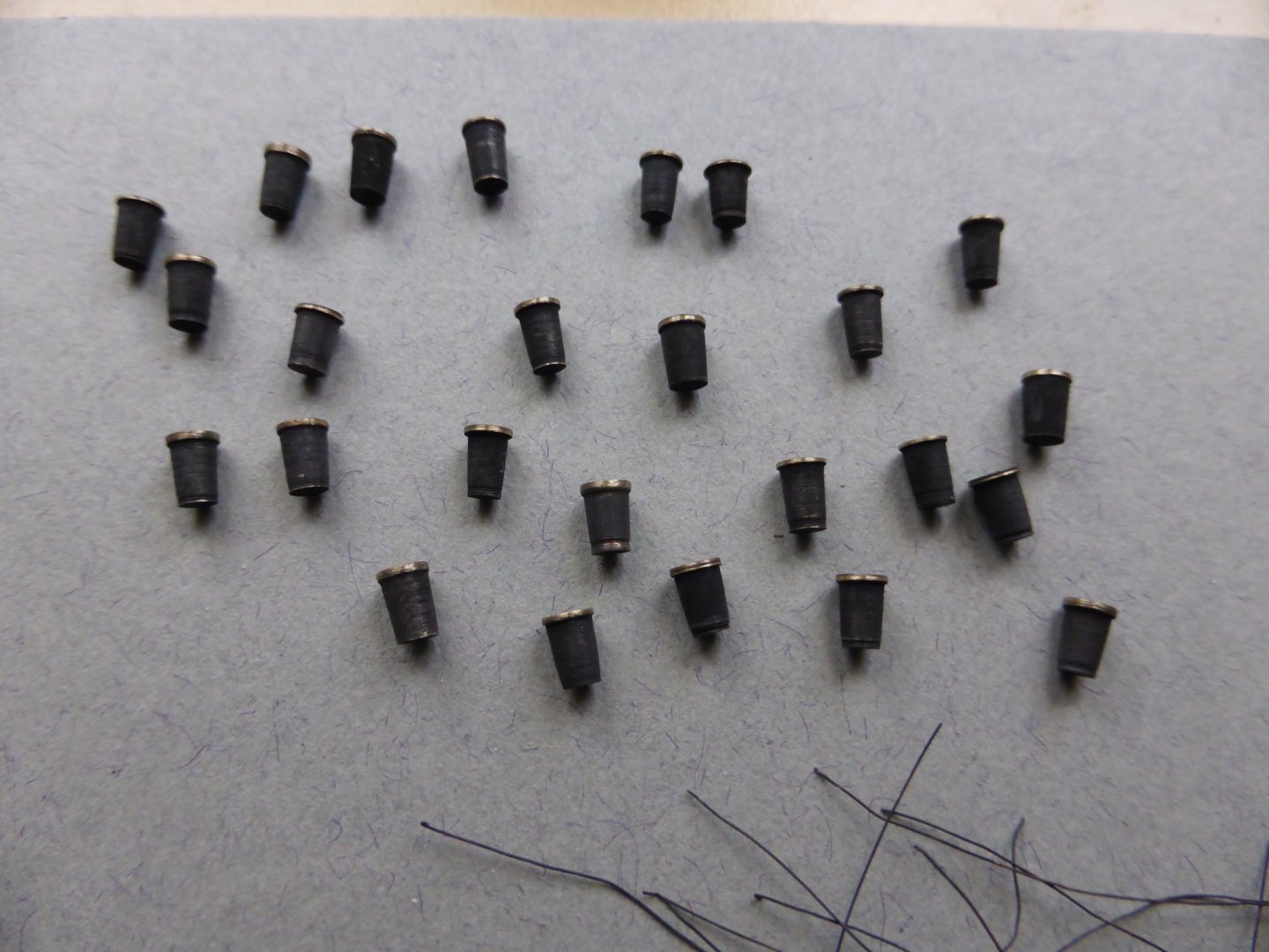
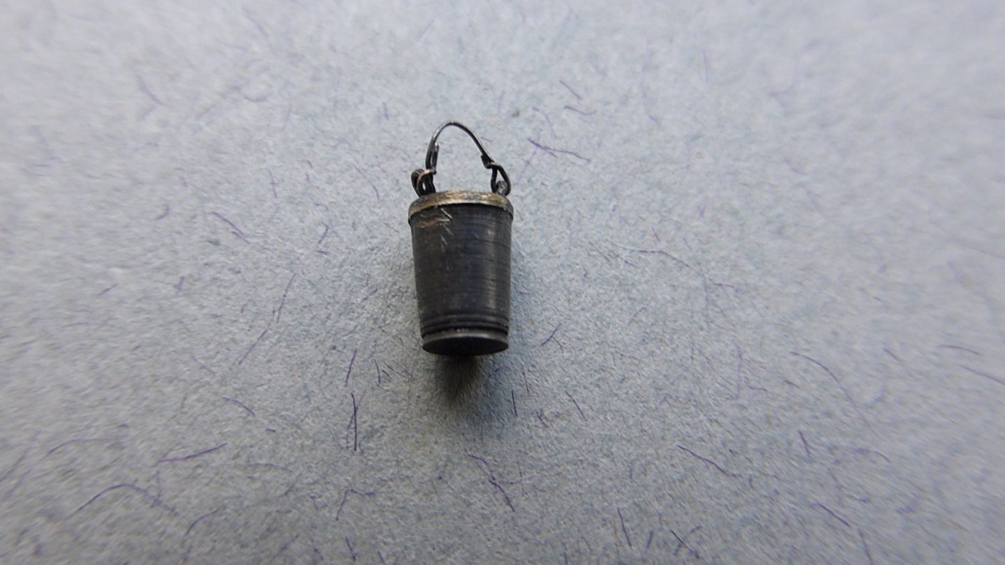
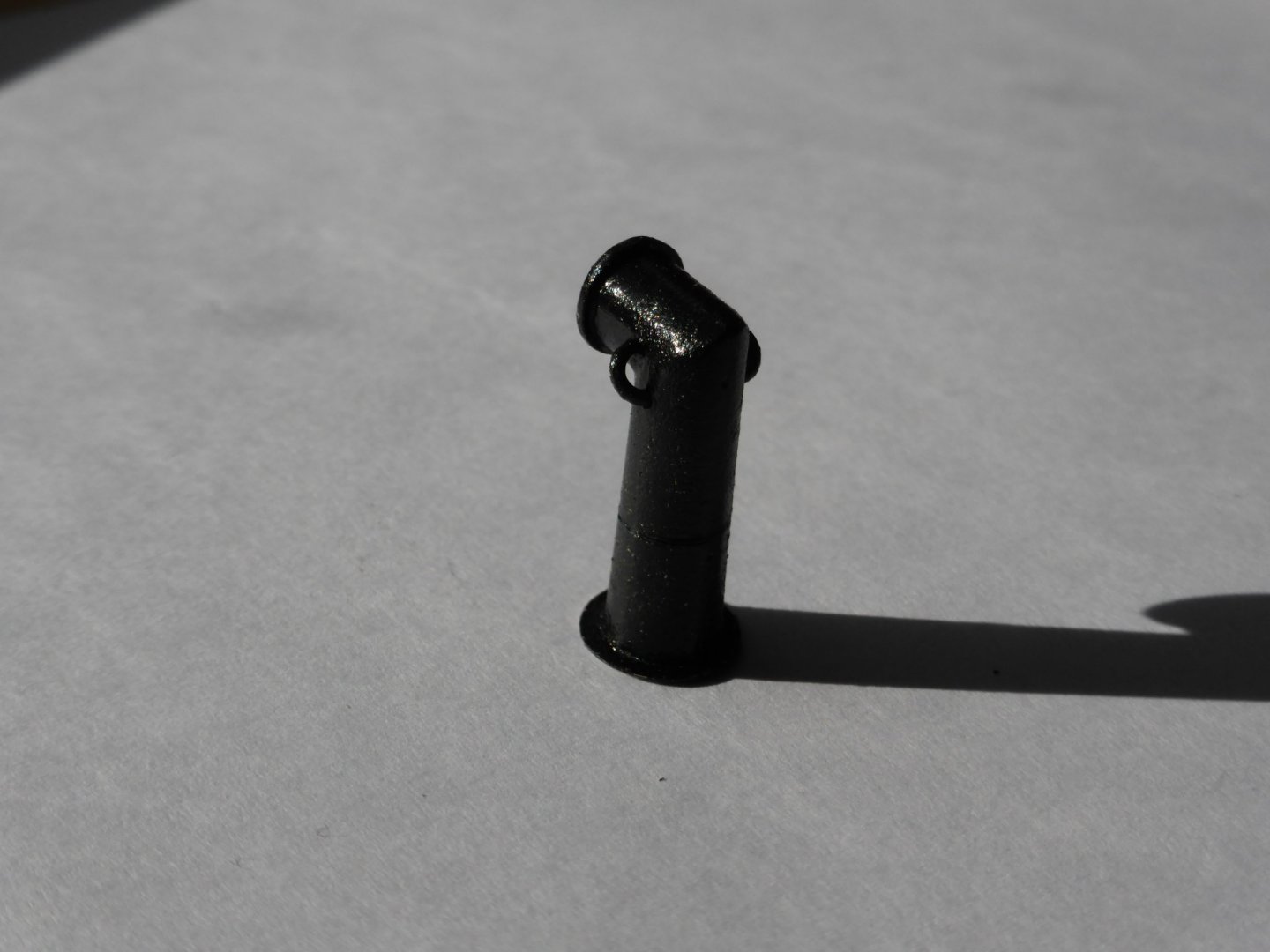
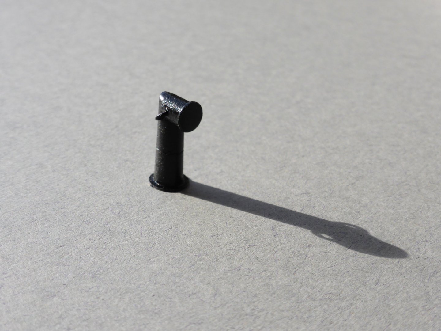
Hi, Thank you for the kind comments and 'likes'. I am genuinely appreciative and humbled. I decided to diverge from the instruction manual and turn my attention to the issue of the fire buckets. I'm not the first to feel that the tapered brass items supplied with the kit, although adequate, are a little bit lacking in detail. To be honest my initial attempts to re-machine the supplied components was not a success! Deprived of access to the workshop machines at school I would usually use because of the current global health situation I have been restricted to using a very old and well used Hobbymat lathe that has definitely seen better days. It has really 'been through the mill' including being submerged in water for a while. We were very fortunate to have the Design and Technology Department modernised and re-furbished several years ago and this meant the total clearance of all the rooms. A lot of equipment, including some that were my own personal bits and pieces, were moved to a boiler house on site. This would have been fine if the electricity company had not had to up-grade the power supply to that area. They negated to fill the trench that they had dug to install the new cable and a couple of days of storms and torrential rain left the building's floor under at least a foot under water. The fact the lathe would even work once it had dried out was a surprise. The difficulty I had with the buckets was finding a safe and effective way to mount them to allow the re-modelling being carried out. In the end I had to admit defeat and think of a different approach. I was fortunate to have a short length of 6 mm brass rod at home and made the replacement buckets from scratch. If I found one of my students making this type of cut with a parting tool like this I would not be happy! - but under the circumstances.... My intention was to achieve a result that mimicked the metal band around the lip of the buckets and the slight flair at the base where the bottom was riveted in place. The latter was achieved with a careful touch with a needle file. After blacking with Birchwood Casey Brass Black solution, the top band was taken back to bare metal with 'wet and dry' abrasive paper. Eyelets were added for the handle. The instructions say to use 0.1 mm thread for this, but I decided to use copper wire strands from a scrap of 13 amp multi-strand electrical cable of similar thickness to replicate the leather straps, also blackened in the same way. Adding these proved a bit of a challenge. One down, twenty, plus a few spares to go... Whether it's possible to add the distinctive GR and crown cipher may prove a step too far - but, to quote Baldrick from the 'Black Adder' TV series - I have a cunning plan....... I'll share this in the event of it actually working....! Teaching a 'practical' subject via a computer at home for eight hours plus a day is hell!!!! MSW and my model help maintain my sanity. Take care and stay safe, Graham.

-
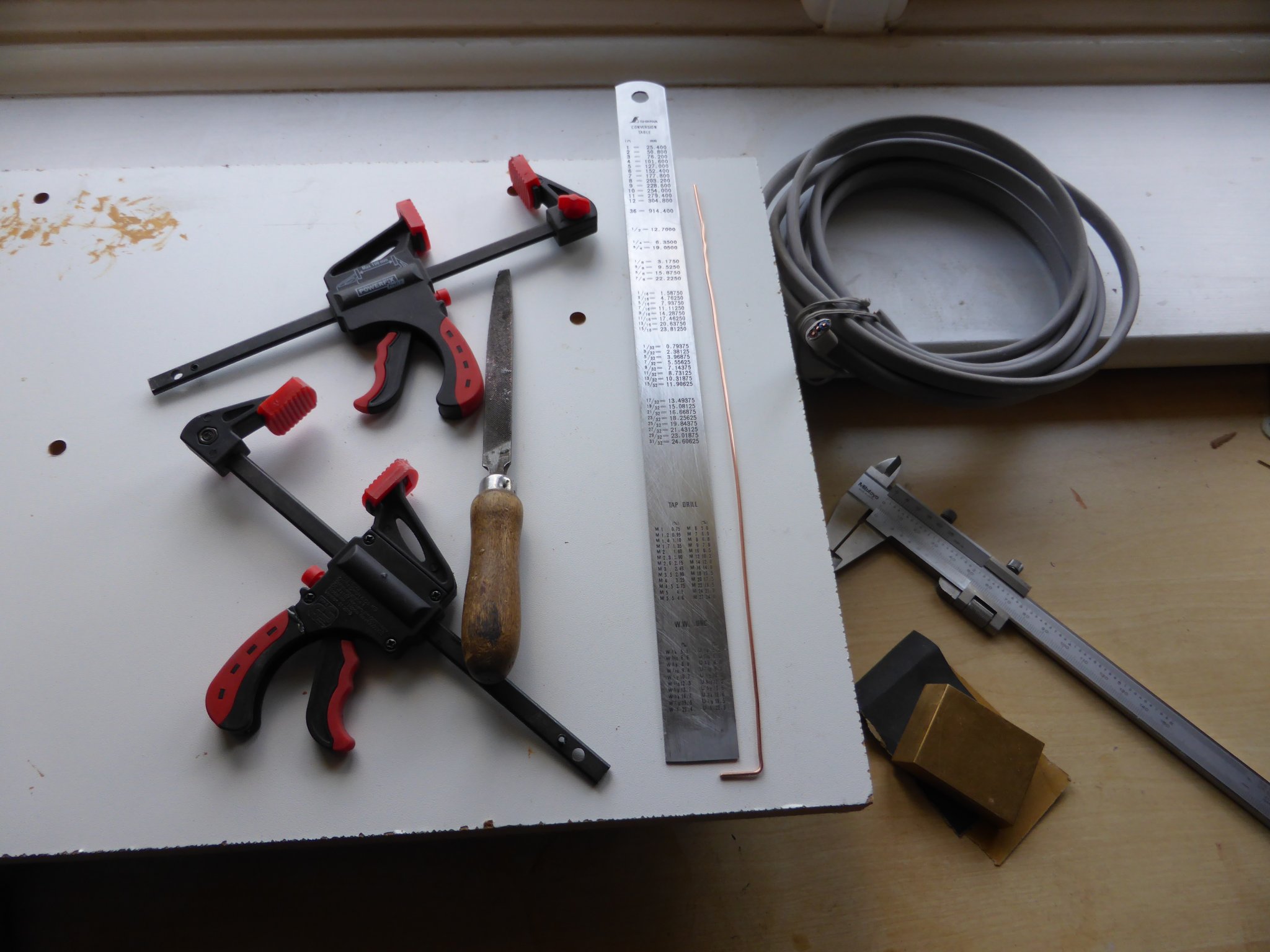
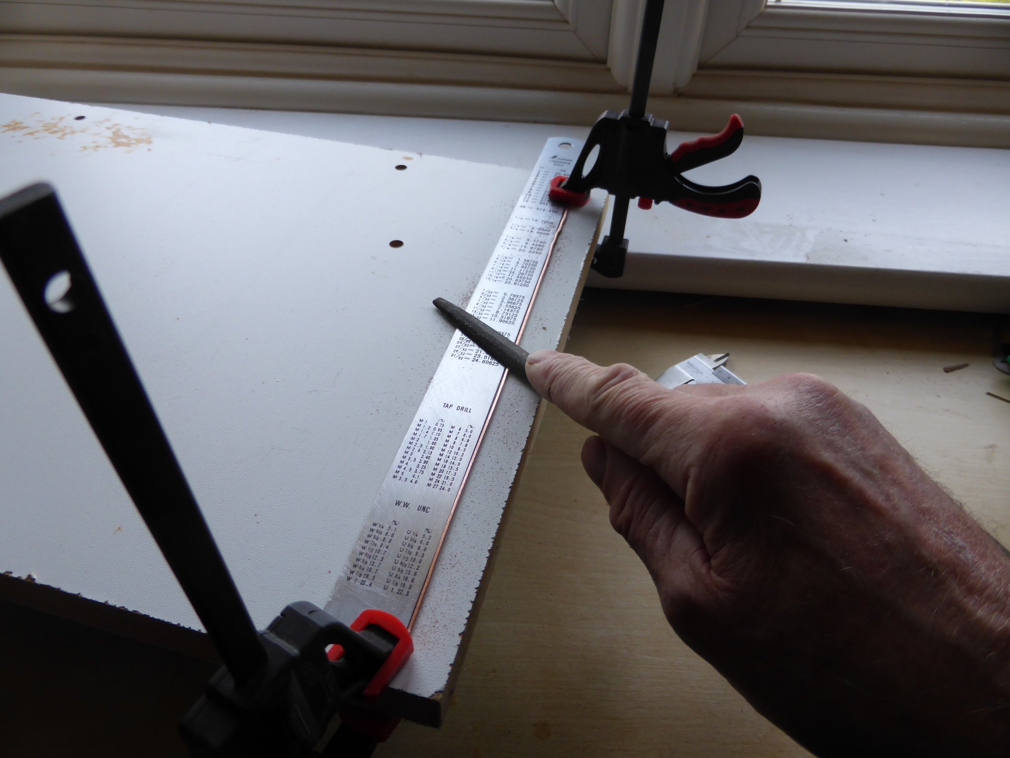
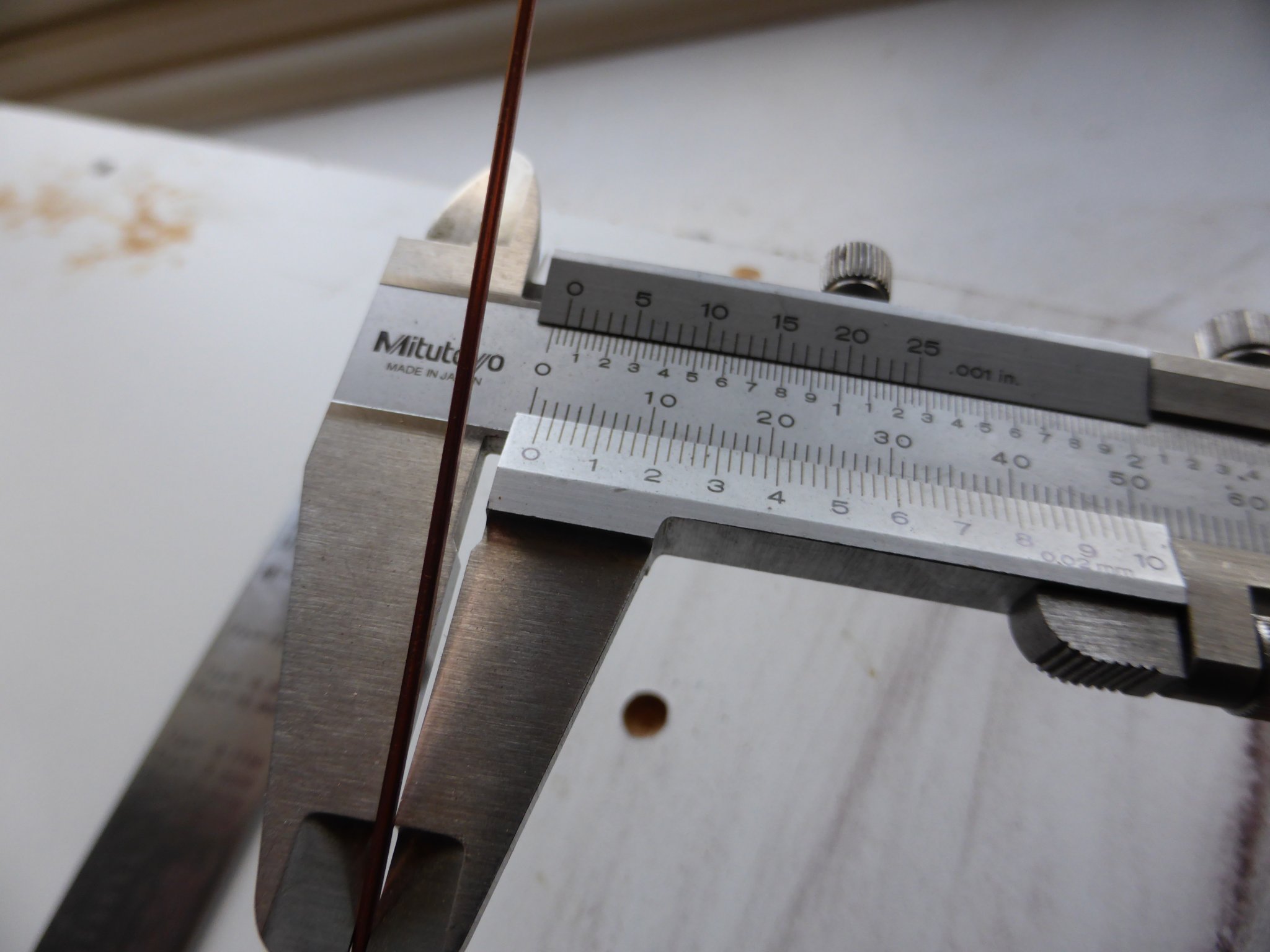
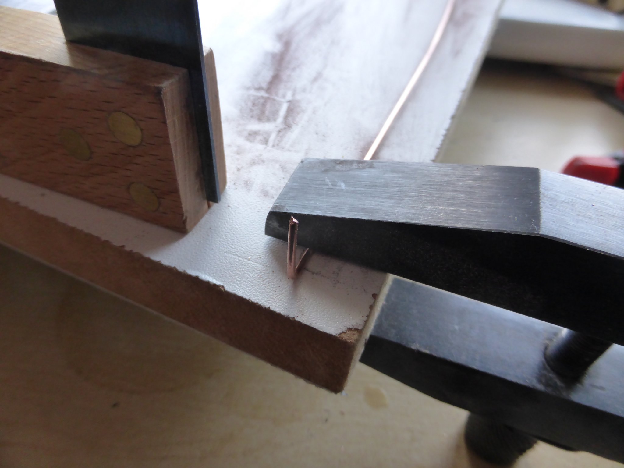
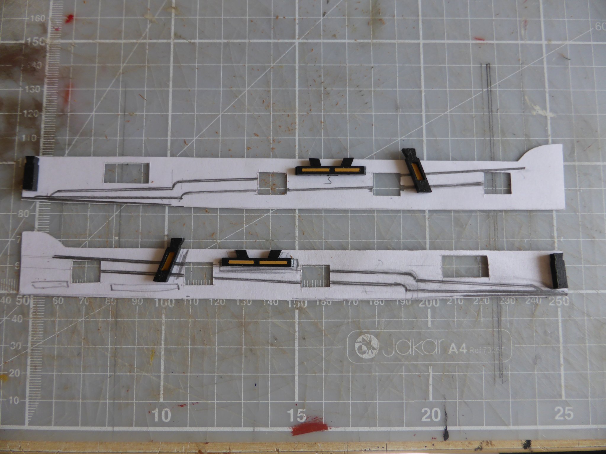
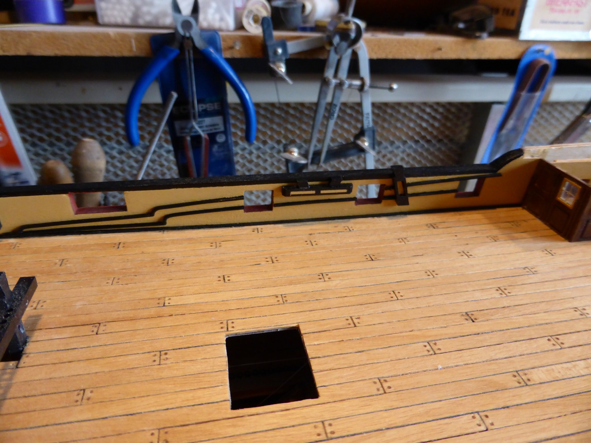
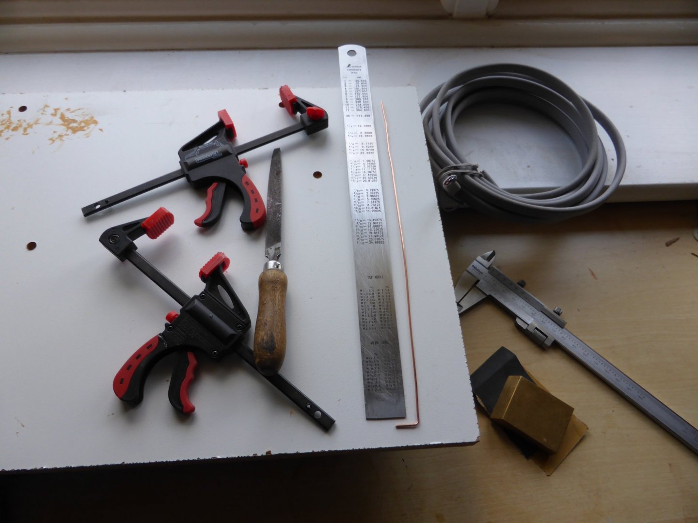
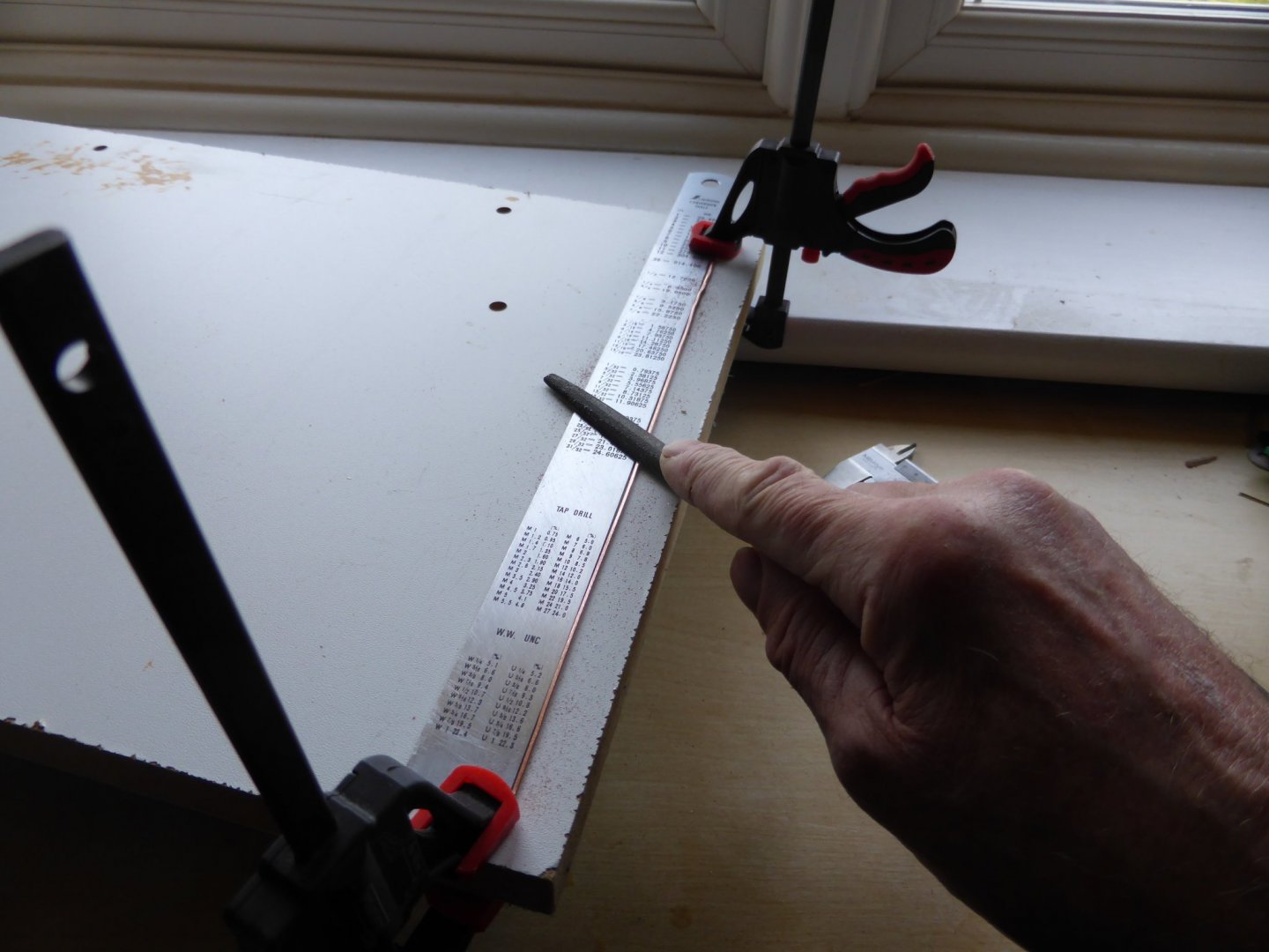
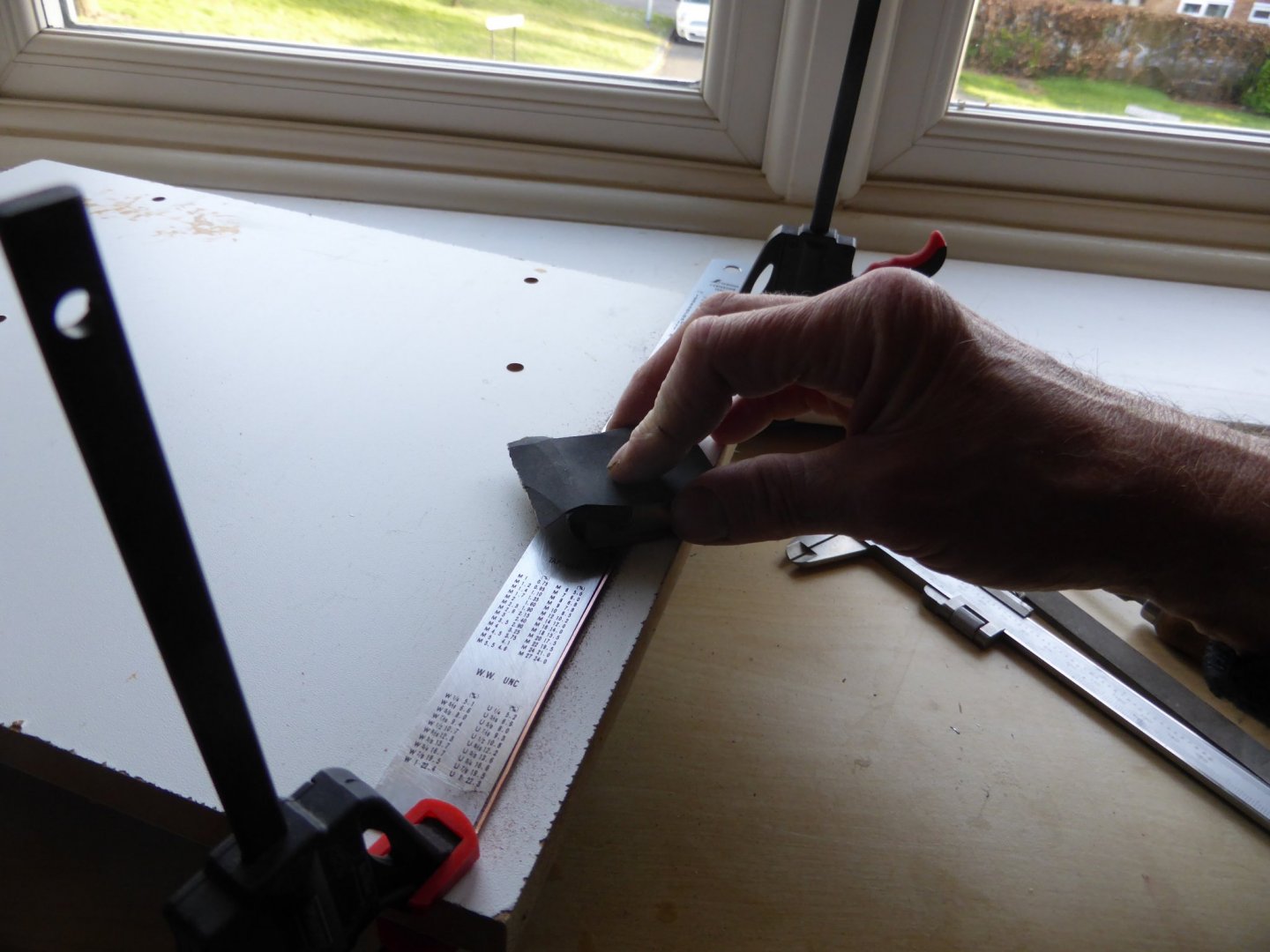
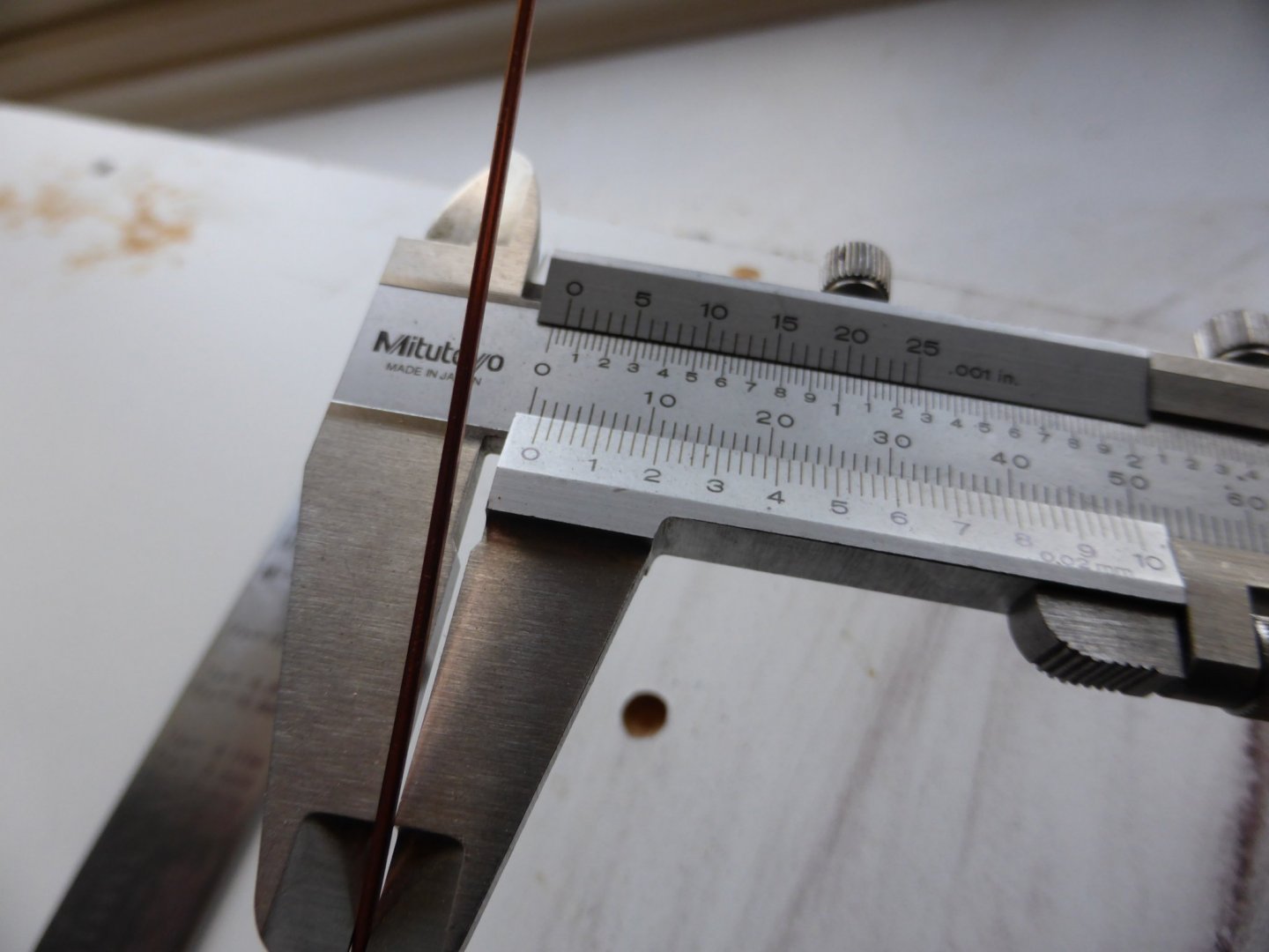
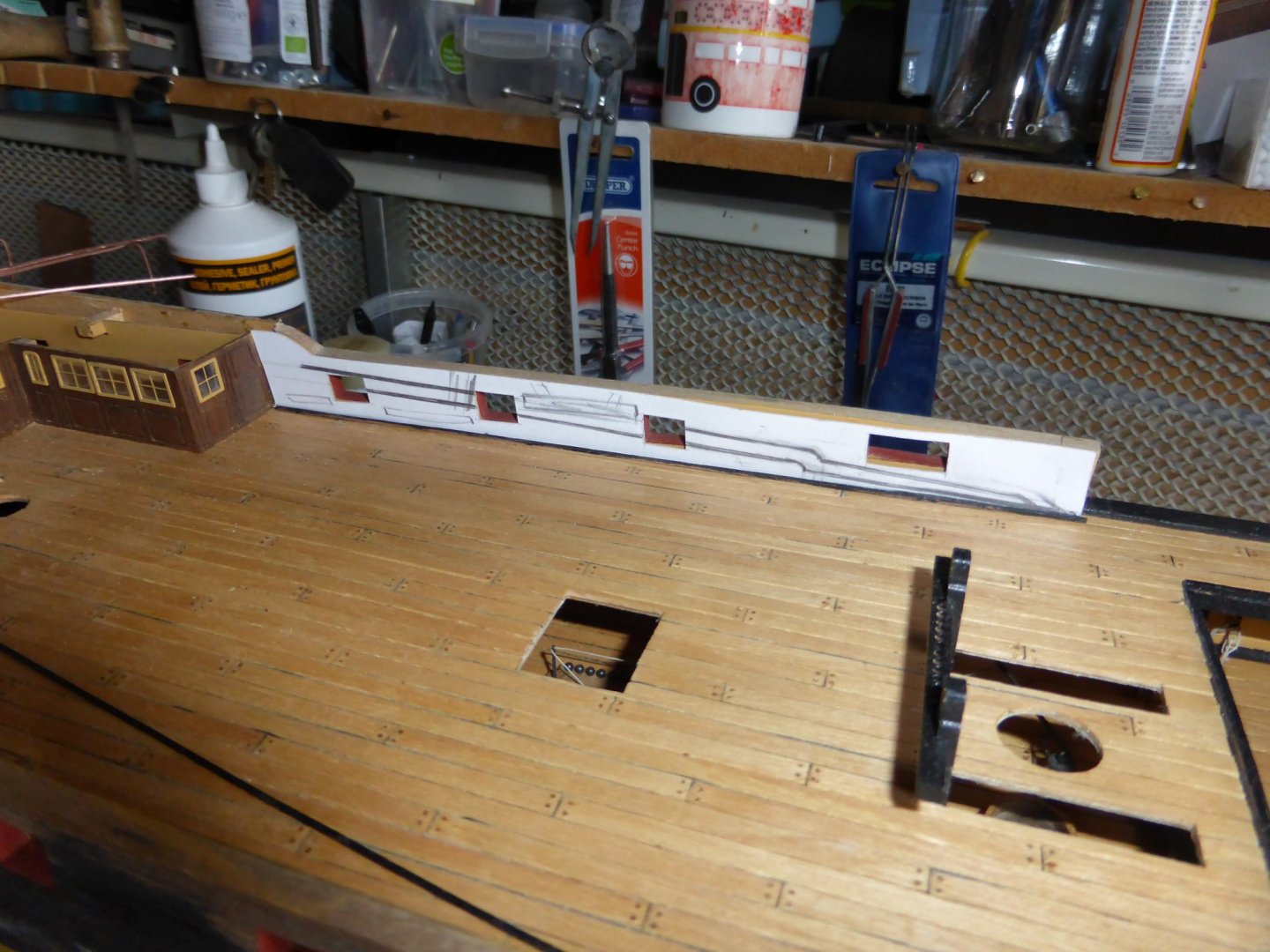
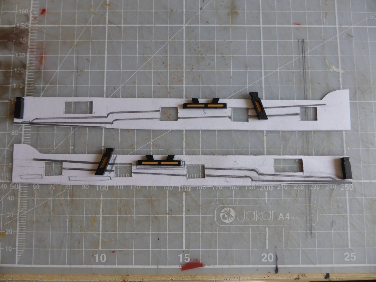
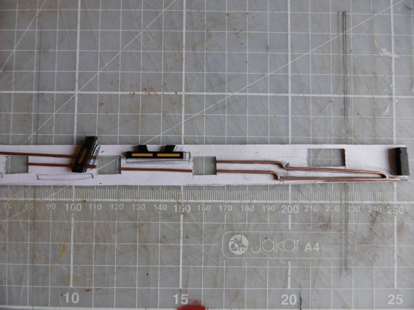
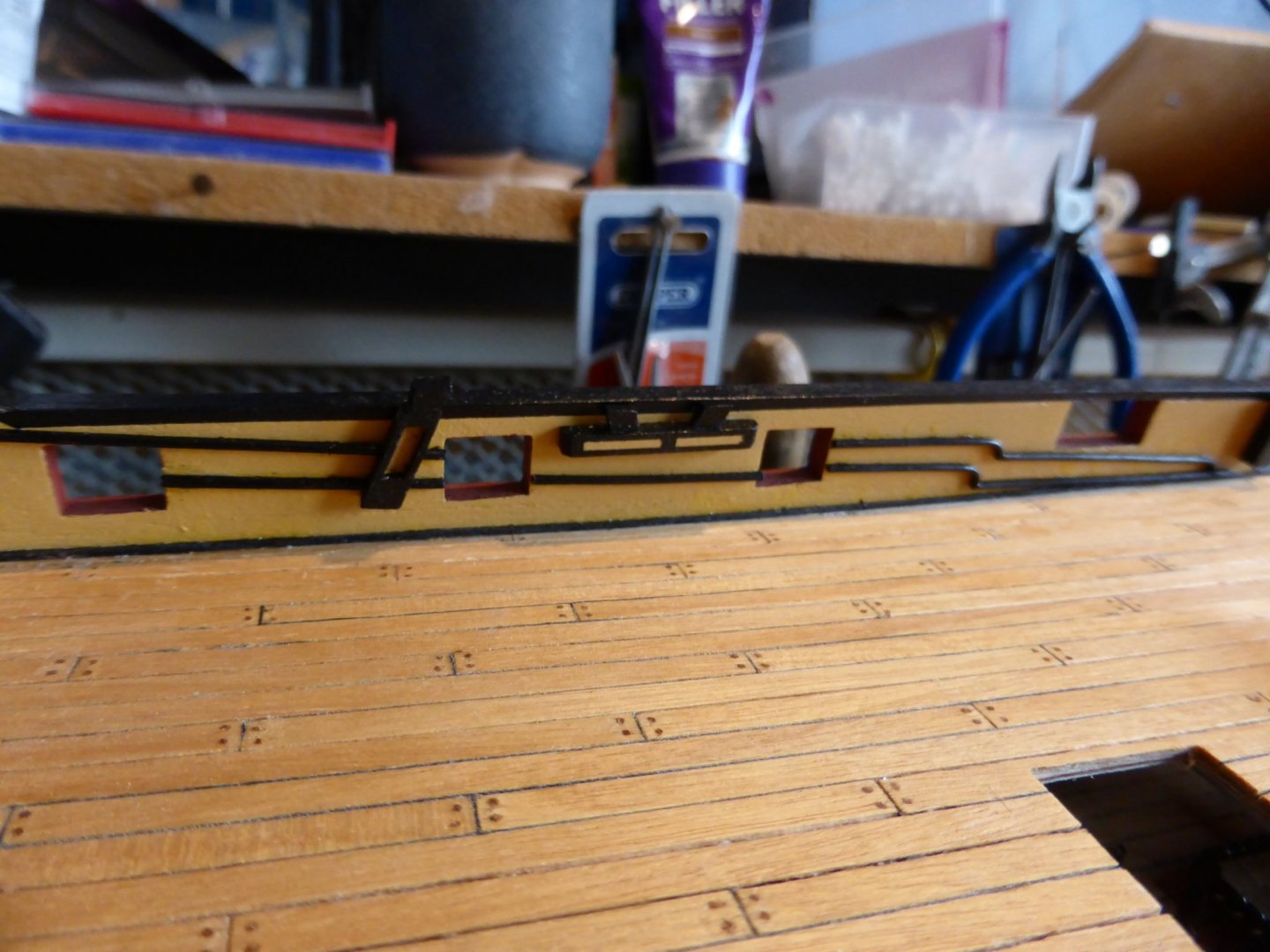
With the completion of the Quarterdeck Barricade assembly a minor psychological milestone has been reached - I'm exactly half way through the first instruction manual! Before finally fixing it place, together with other deck fittings, I wanted to add more detail to the inner bulwarks, notably the black mouldings that feature so significantly on the scale 1:1 version in Portsmouth, something the original kit omits. With building materials unavailable from local model shops which are now closed for the foreseeable future it was time for a bit of improvisation. I do have some 1 x 1 mm mahogany strip stashed away but there was no way it was going to bend to the curves without breaking. Another one of those moments when a reluctance to bin anything that just 'might be useful one day' bore fruit - a short length of twin and earth cable left over from a bit of DIY many years ago was pressed into service. The central copper earth wire is 1.3 mm diameter. I needed it to be 1 mm. Using an old steel rule of the required thickness as a guide, lengths of wire were filed .......... and then finished with abrasive paper. The 90 degree bend at the end, once rotated 180 degrees, allowed for opposite sides to be flattened to the right thickness. This bend was then twisted 90 degrees so the third side could be finished. The remaining side was left with the radius that would eventually face inboard. Card templates were cut to aid drawing the correct profiles ........ and with other features like the kevels and staghorns in place the copper strips were cut, bent, filed and soldered. And finally, after a couple of coats of dull black paint these were fixed into position. Shot garlands to follow..... Take care and stay safe in these challenging times, Graham.


-
Welcome back!! I look forward to following your progress again - I often look to your Build log for inspiration, and those photographs you took on board are a significant research source when I try to add detail ...... thank you. Graham.
- 414 replies
-
- 1
-
-
- caldercraft
- victory
- (and 1 more)
-
HMS Victory by Helli - Caldercraft
Charter33 replied to Helli's topic in - Kit build logs for subjects built from 1751 - 1800
Hi Helli, I've had this problem once as well. I think I solved it by clicking on edit, then deleting the pictures from the bank of imported photos at the bottom. I believe it was necessary to hover over the thumb nail picture for the X to appear. I'm no 'IT techy', but it might be worth a try. Good luck - and a very nice build you have there! Graham -
HMS Victory by Helli - Caldercraft
Charter33 replied to Helli's topic in - Kit build logs for subjects built from 1751 - 1800
Copy all the ideas you like, a lot if them I picked up from here too! My absence was not through choice, I assure you, but it really is good to be back at it. Some interesting R/C aircraft in the background there..... Cheers. -
HMS Victory by Helli - Caldercraft
Charter33 replied to Helli's topic in - Kit build logs for subjects built from 1751 - 1800
A great start Helli. I look forward to watching your progress. Welcome to the Caldercraft Victory club! Cheers, Graham -
Hi Will, Lovely grain, very much like the figuring - my guess is walnut, but not the grade usually found in model ship building. As a veneer there is a beautiful box crying out to be encased in this........ my fingers and creative juices are itching in anticipation, you are one lucky bunny to have this to play with - good luck! (oh so jealous!) Cheers, Graham
-
Hi, Thank's for the comments and 'likes' gentlemen - always genuinely appreciated. Robert - your photographs of the original ship are proving to be a great source of information, as is your own impressive build log - thank you. Wallace - welcome aboard! In fairness I feel I should flag up the observation that has occasionally been made on this site that although the main aim of this hobby is to complete a well made model, the journey travelled to achieve this is equally, if not more, enjoyable and important. That said I must confess that sometimes I will occasionally climb off and break the journey, take a deep breath and admire the view for a while, usually by choice, but sometime forced by circumstance. It's taken a while to get to the current stage, and there's a long way to go - but I will get there, eventually. No pressure..... Cheers, Graham
-
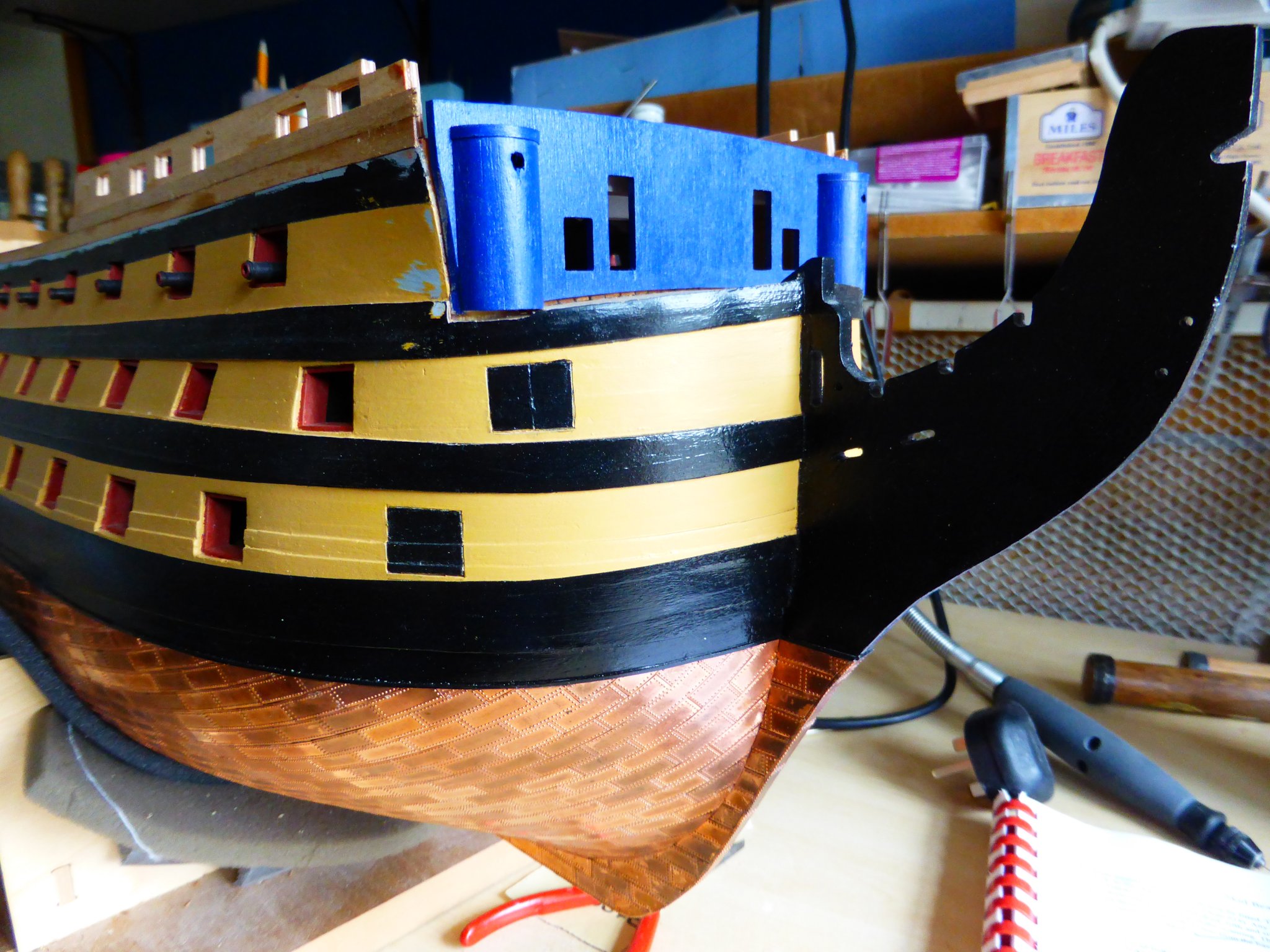
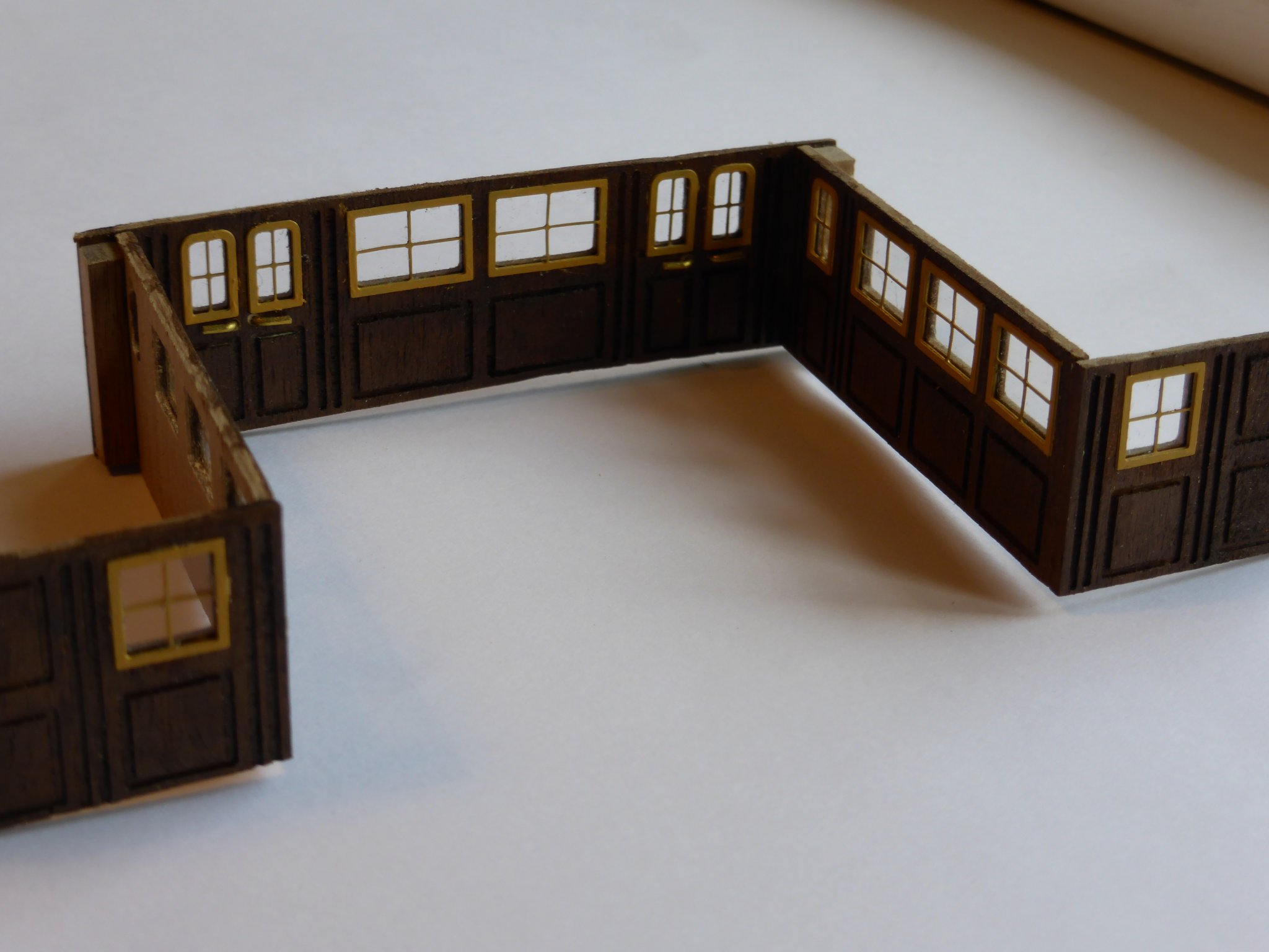
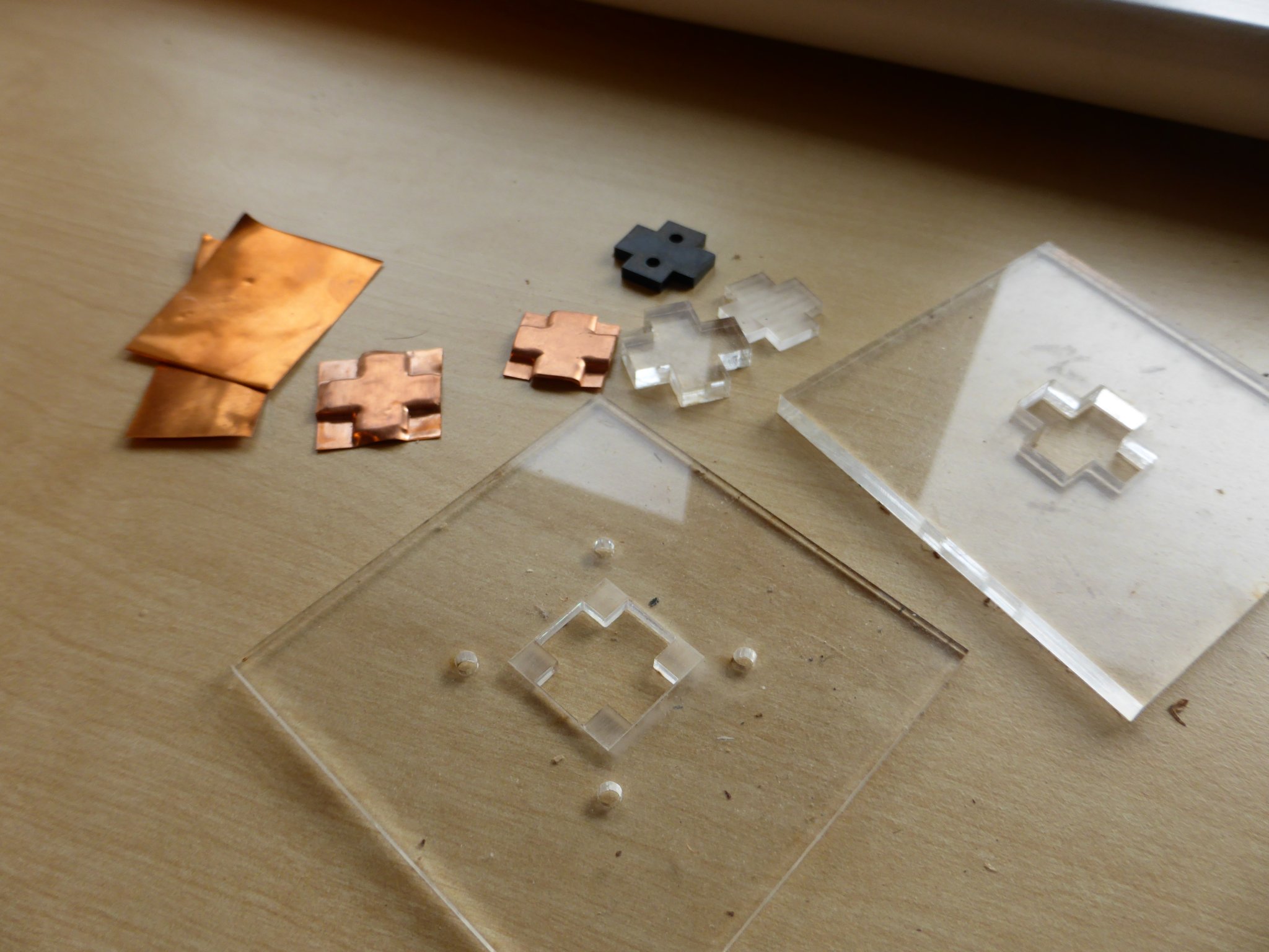
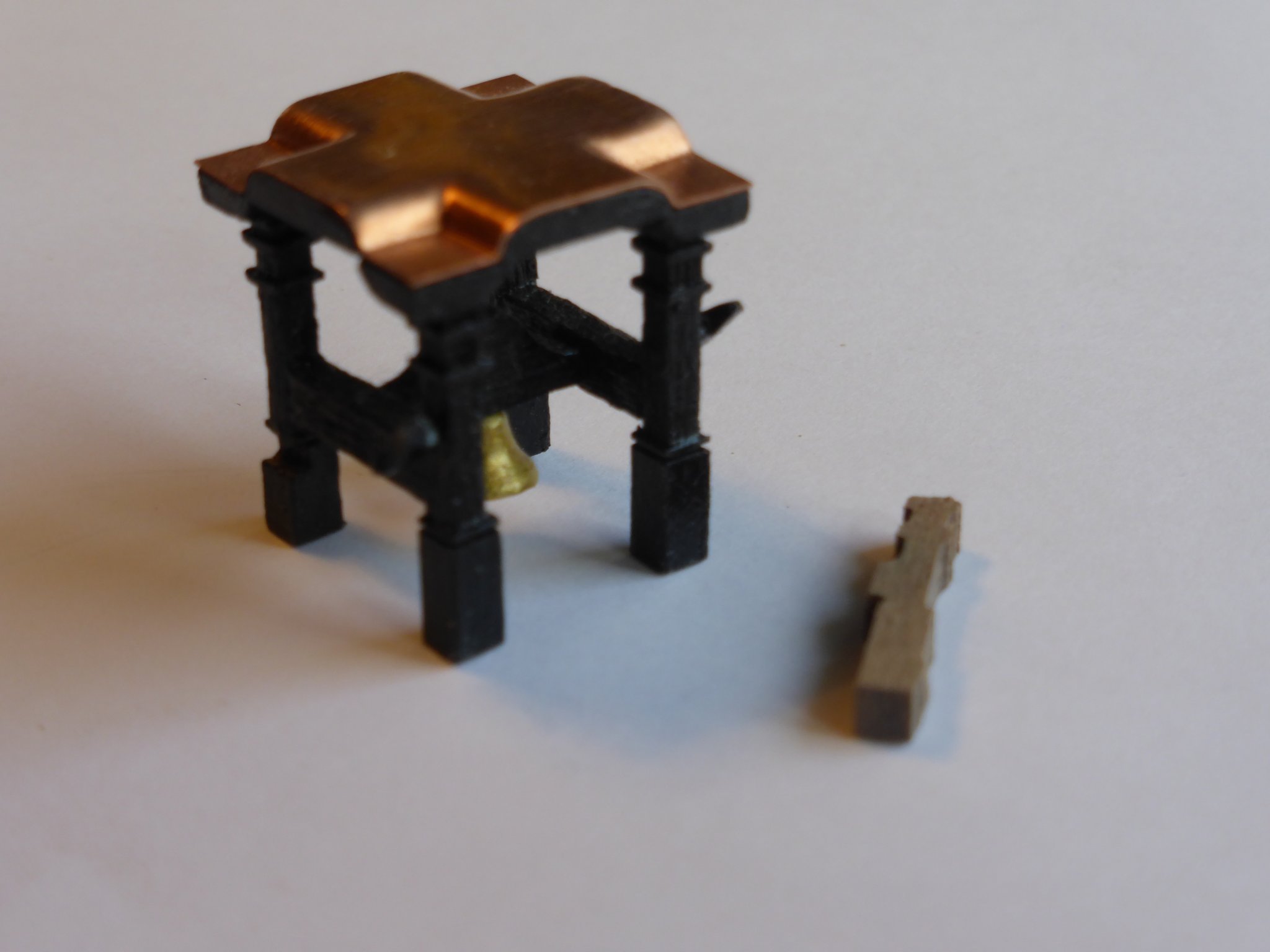
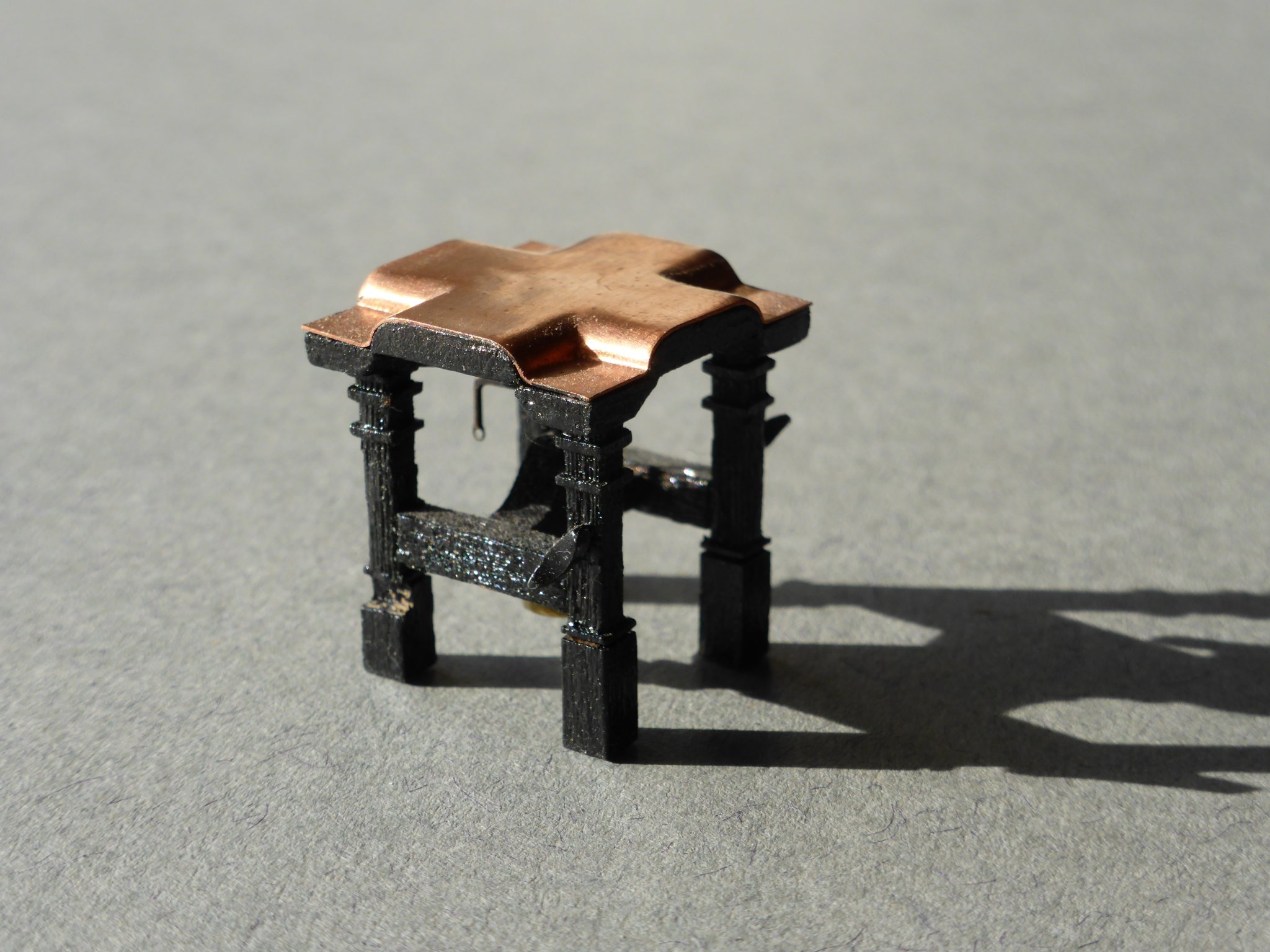
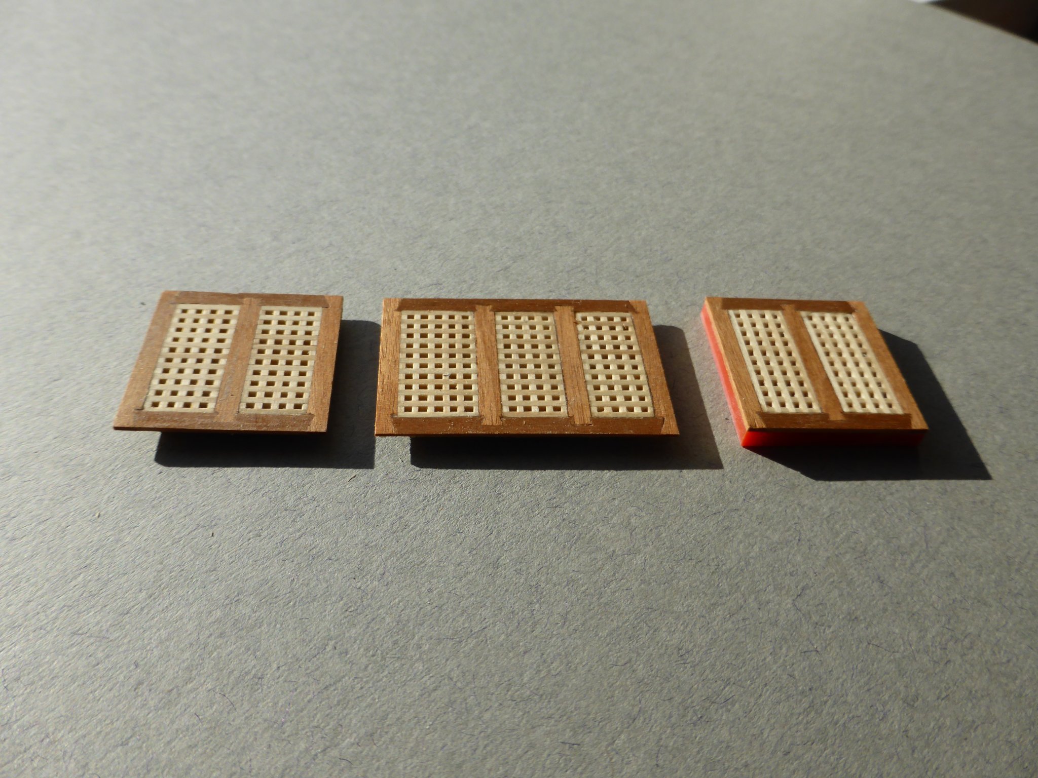
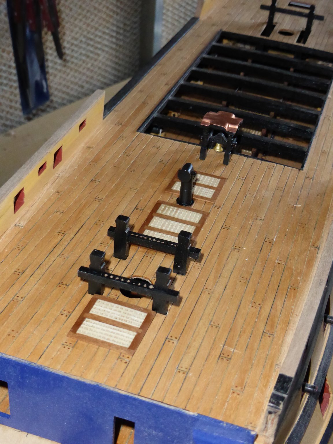
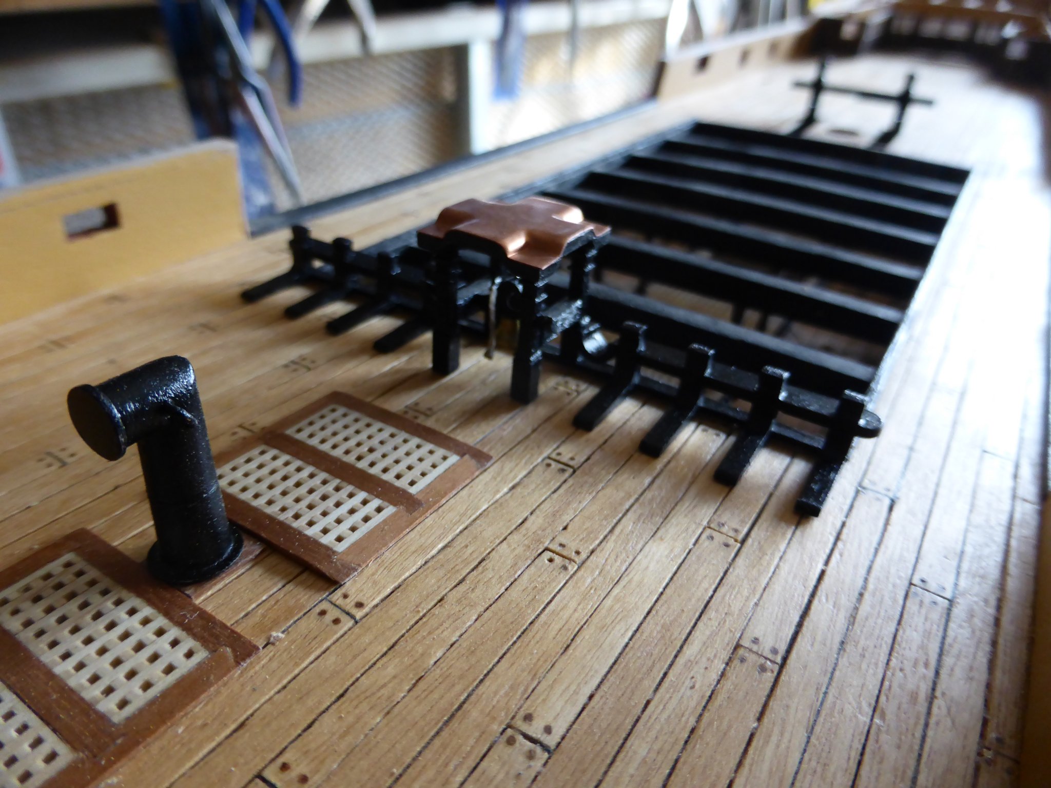
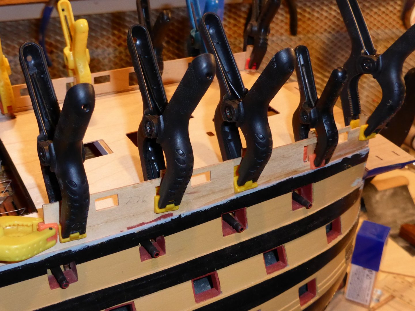
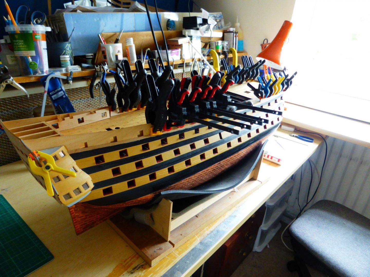
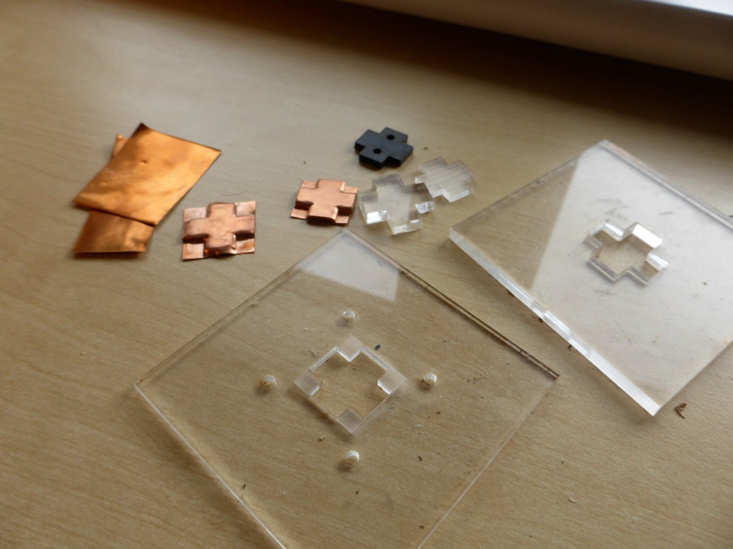
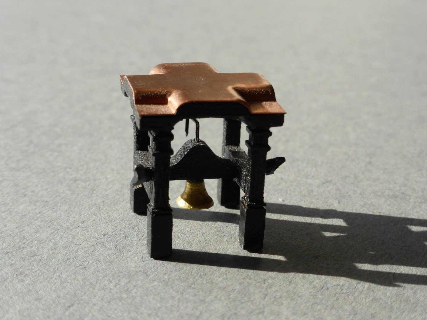
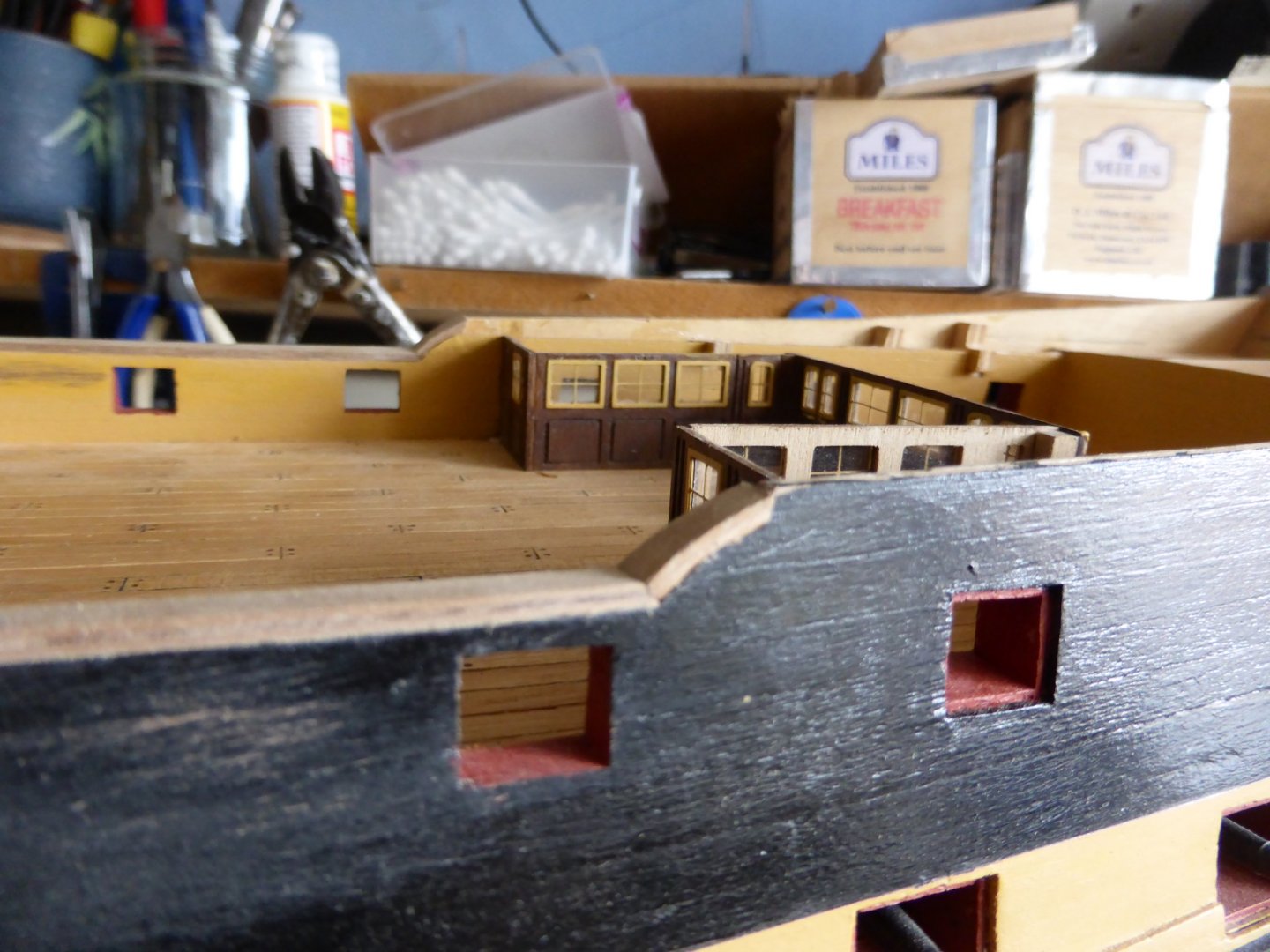
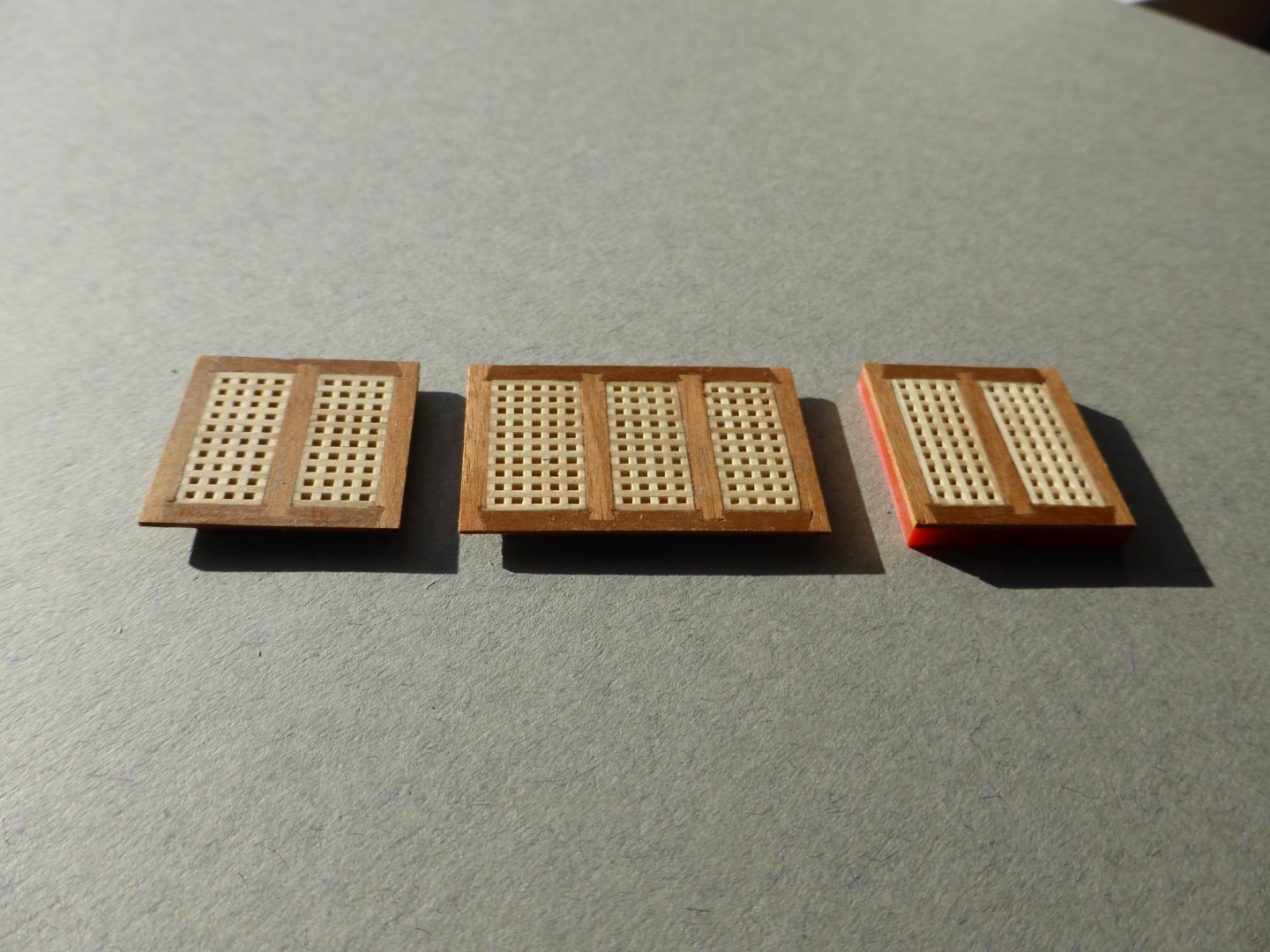
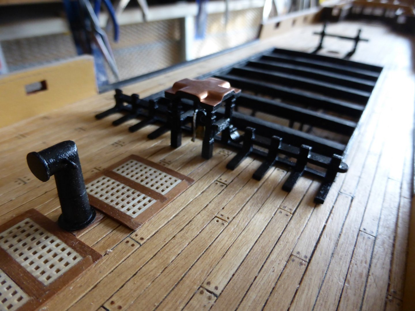
Hi, I can't believe it's over a year since I last added to this build log.....! Here are some details of the progress that I have made: With the quarter deck in place it was time to cut the tops off the forward bulkheads. Next job was to re-install the outer forecastle gunport strips that had been removed following the advice of Shipyard Sid. The beakhead bulkhead had the roundhouses fitted and was painted. It will have the additional decoration added before it is finally glued into place. It’s currently just dry fitted. With the deck planked and tree nailed, using the method previously explained, and inner bulwarks fitted… …. I made up the quarterdeck screen assembly...... I decided to try and produce a modified version of the belfry. The uprights provided in the kit seemed to lack detail of the mouldings as shown in John McKay’s ‘Anatomy of the Ship’ and were restricted to just the front and back surfaces. I also wanted to replicate the copper roof. After a bit of experimentation, and a few failures, I came up with a way to press form thin copper sheet into an acceptable shape. This is the result ….. Second planking on the outside of the hull and inside the bulwarks was completed, gunports lined and then all painted. The cap strips were glued into place. I couldn’t find anything provided for the small curved sections just ahead of the poop deck so laminated some. Two strips of walnut were soaked and then clamped around a former, in this case a wooden collet I had made to hold ‘turned’ wooden components for some automata I’ve been making. Once they had dried these were glued and re-clamped before being cut and sanded to size and fitted into place. Forecastle gratings were assembled but I chose to make them up separately from the deck rather than following the method outlined in the instructions. Having gone to the trouble of trying to replicate the dovetail details of the coaming joints on the gratings on the previous deck, (which are now hardly visible!), I was keen to try and do the same thing here. Probably the hardest aspect was trying to sand the slight curve that was needed on the top surface. The galley chimney was given a bit of attention with the addition of two handles and the impression of the seam on the main body prior to painting, using pictures of the chimney found on-line as a guide. The Forecastle Breast Beam assembly has also now been completed. All these pieces are dry fitted and will be glued in place once some more painting has been done, including the cap strips, and a few other additions have been added to the inner bulwarks. Cheer for now, Graham.


-
De Havilland DH 60 Gipsy Moth by Mike P - 1/4 Scale - WOOD
Charter33 replied to Mike P's topic in Non-ship/categorised builds
Gorgeous!!!! A stunning build..... thank you for sharing Graham -
Hi Mark, Without doubt a bold choice for your first model ship! Having said that I should own up and admit that it so happens that it is my own 'second' build and as a relative novice I can appreciate where you're coming from. You're in for a great journey and joining this forum is probably the best thing you could have done to help you on your way, There are some stunning build logs here and I could not have made the progress I have without the sage advice of other members. Many build logs are now my first port of call when tackling new and challenging stages. Of the builds currently under way I recommend the work of 'Bertu' as a good starting point but there are also many others - using the search function to find these builds is time well spent. As for helping other novices to benefit from your expected mistakes, take look at my log - I made some real howlers! Looking forward to seeing your work. Cheers, Graham
-
Another stunning picture - and just a hint of Turners 'Fighting Temeraire' in the sunset and juxtoposition of sail and steam? Love it. Thank you.
-
Laser cutting questions
Charter33 replied to SardonicMeow's topic in Modeling tools and Workshop Equipment
Just a quick note - there are grades of ply that are produced specifically for laser cutting - we use them with the students at school. They char much less than birch ply of similar thickness. Another tip - when cutting wood with the laser cutter I often set the machine up to run at a lower power / faster speed setting and repeat the cut several times until full penetration is achieved. I developed this technique when teaching myself how to use the machine and software by drawing and cutting components for an R/C model aircraft from balsa wood. This reduces burning and is very useful for those small or delicate parts. I have successfully used this on lime (basswood), mahogany, yew and cherry - although not necessarily all for model ship building. I also fully agree with the previous post about using MDF... Best way to learn is to dive in and 'play'. Good luck! Graham. -
I'm just grateful we have such a variety of modern alternatives to chose from. 40 'coats' might sound extreme but 'bodying up' the surface, especially on an open grained timber quickly accounts for many, and several can be applied in one session before the rubber starts to grab. I share the preference for a less glassy finish, but watching a skilled polisher achieve one using a clean rubber soaked in meths, hovering just above the surface of the polish with just the fumes producing the final finish is a inspiration.
-
I use both pumice powder and rottenstone to refine french polish, reducing a 'glassy / gloss' finish to a satin or more matt finish. I usually use a soft lint free cloth dipped in a little linseed oil to pick up the powder and, as Druxey says, use a circular motion to apply it to the french polished surface. To achieve a good finish can take up to 40 coats of french polish, but the biggest difference between shellac polish and other varnishes is the way each layer dissolves into the previously applied layers rather than lying on top. It's this that produces such a beautiful effect. Not sure I'd use this on a model ship itself, but probably on a stand or display cabinet. Hope this is of some interest. Graham.