HOLIDAY DONATION DRIVE - SUPPORT MSW - DO YOUR PART TO KEEP THIS GREAT FORUM GOING! (Only 13 donations so far - C'mon guys!)
×


druxey
-
Posts
13,290 -
Joined
-
Last visited
Content Type
Profiles
Forums
Gallery
Events
Everything posted by druxey
-
 Models that I've seen usually do not curve around quite so much. However, do you notice that triangular piece seen on the stern view? It sits on the outer end of the wing transom. Is this a separate piece or is it cut into the aft end of that wale plank? If the latter, this is something new (at least, to me!).
 -
Well, I can't definitively say it's the right track, but it does work!
-
Beautifully done, Patrick. Bien fait, monsieur! Je tire mon chapeau. (I tip my hat to you.)
-
It is a very tricky area indeed, Mark. On my 64, I had to also carve a shallow rabbet on the inner side of that aftermost wale piece so that the bottom plank below it could curve around smoothly and in contact with the frames. Whether this was exactly what was done in full-size practice I cannot say, but seems reasonable. There was still a small triangular gap that was filled with a piece of plank outboard of the last bottom plank.
-
Hardly worth the trouble: the gale would have blown over by then!
-
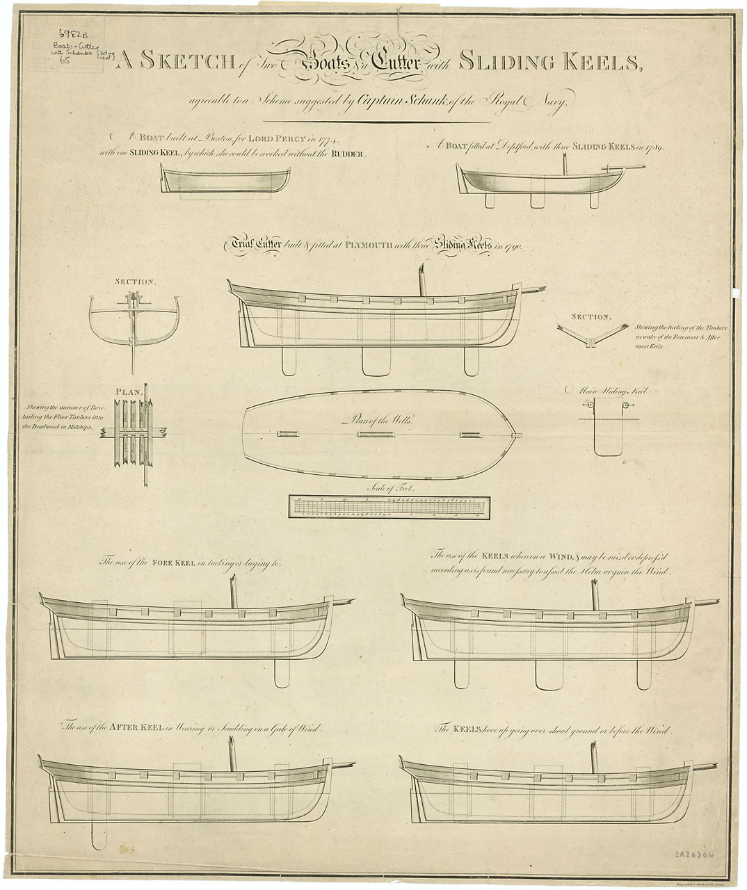
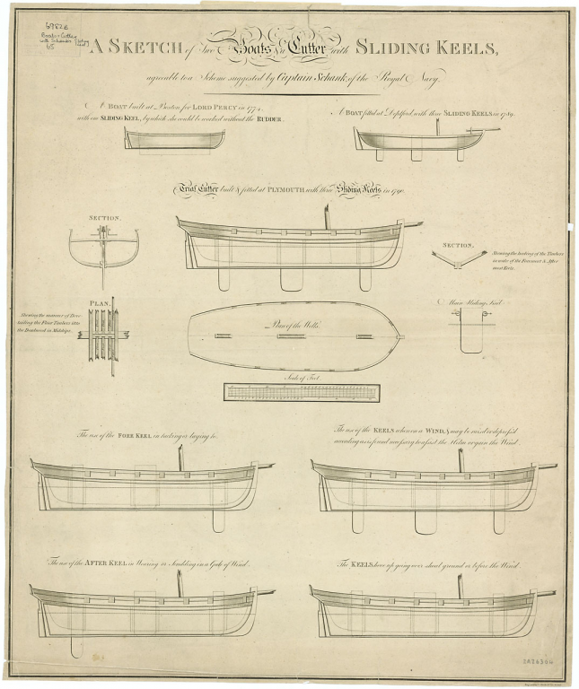
Not American, but the right era and size: search Schank sliding keel on the RMG web site under 'Collections'. There are several pages of plans of vessels as well as the raising/lowering mechanisms. An example is here:
- 525 replies
-
- 5
-

-
- anchor hoy
- hoy
- (and 1 more)
-
Congratulations on a fine finishing flourish! So, what's next?
- 525 replies
-
- 2
-
-
- anchor hoy
- hoy
- (and 1 more)
-
Watchmakers' tweezers, perhaps?
-
Deck plank detail
druxey replied to Srodbro's topic in Building, Framing, Planking and plating a ships hull and deck
Such joints are generally referred to as tabled joints. -
All I can see missing is a nice nameplate mounted on the baseboard, Maury. Otherwise, it's really nice to see a lesser-modelled subject. Congrats on a job well done.
- 525 replies
-
- 2
-
-
- anchor hoy
- hoy
- (and 1 more)
-
Well researched and well reconstructed. I'm in awe of your courage in tackling a ship of this era and producing such a convincing result. Altogether a lovely job, Dick. Congratulations!
-
Yes, if you can refer us to where to find the picture, that would be very helpful.
-
ancre Chebece 1750 by Jeronimo - FINISHED
druxey replied to Jeronimo's topic in - Build logs for subjects built 1501 - 1750
Finding the first grating assembled incorrectly must have been very annoying. Hats off to you re-making it correctly! Lovely cannon castings as well. -
I hate to mention this and hope it's an artifact of photography, but the hull appears to be developing a slight twist (check the last stern-on photo). If so and I'm right, it should be correctable at this point. Nice, clean work though.
- 607 replies
-
- 9
-
-
- winchelsea
- Syren Ship Model Company
- (and 1 more)
-
Nice sketches, as others have already noted, Mark. That problematic last piece was apparently shaped rather than bent in the shipyard, so you are in good company. Carve the inner surface first, fit the joint, attach, then carve/file/sand the outer surface to shape, would be a good strategy. Good luck with it!
-
Aiee! What happened to good, old fashioned, simple smokestacks? These are far more complicated than given by their first impression. Well done, Dan.
- 287 replies
-
- 4
-
-
- michelangelo
- ocean liner
- (and 1 more)
-
I use rubber cement for my sanding blocks. Use it like contact cement. However, the sandpaper is more easily peeled off for replacement.
-
Yes, Museum quality UV-filtering glass is not cheap stuff. Thanks for the details of your casework. I hope the stain didn't go onto anything else!
- 525 replies
-
- 4
-
-
- anchor hoy
- hoy
- (and 1 more)
-
I guess that a lot of fertilizer was applied....
-
Well, that is a pleasant surprise! I hope they deal fairly with you.
- 346 replies
-
- 4
-
-
- terror
- polar exploration
- (and 2 more)
-
Very, very impressive model shipwrightry!