HOLIDAY DONATION DRIVE - SUPPORT MSW - DO YOUR PART TO KEEP THIS GREAT FORUM GOING! (Only 13 donations so far - C'mon guys!)
×


druxey
-
Posts
13,290 -
Joined
-
Last visited
Content Type
Profiles
Forums
Gallery
Events
Everything posted by druxey
-
See the sail supplement booklet to the Swan Class series, Volume IV.
-
I believe that 'nitro cellulosic filler' that you are using is called sanding sealer in North America.
-

Weathering wood
druxey replied to JpR62's topic in Painting, finishing and weathering products and techniques
I agree with wefalck: bitumen never fully dries or 'sets'. Problems can become apparent years later. Have you ever seen old brown varnish finishes that have 'alligatored'? That's because they were bitumen based. Acrylic or oil paints in washes are far more reliable. -
There is one problem - I've run out of superlatives to describe your modelmaking skills!
-
Coming along very nicely, Toni. However, watch out for the tilt aft of the lights: yours are too vertical at present, I think.
-
Another classy Woody Joe build! That is a great and unusual subject. Nice job, Mark.
-
Sweet! That's a lot of aluminum (sorry I mean aluminium) and swarf!
-
Blaise Ollivier (1737) does not mention either kind of plate in his extensive commentary on English building practice.
-
Swan class 3D model in progress
druxey replied to dvm27's topic in CAD and 3D Modelling/Drafting Plans with Software
Alas, there is no hope for you, Denis...- 141 replies
-
- 5
-

-
- pof swan series
- swan
- (and 1 more)
-
Michael: I'm also looking forward to seeing this model develop: it's always good to see a subject that is a little out of the usual here!
-
The 'splash of white', as I interpret it, is either a painted highlight or, as in the model, a reflection form a glossy surface. In the first instance, I'd still make it pale blue, as pure white will optically 'jump' too much with high contrast at scale size. Whether I'm right or wrong doesn't matter; it has to please you, Drazen!
- 487 replies
-
- 2
-
-
- ship of the line
- 80 guns
- (and 1 more)
-
Continuing excellent progress, Amalio. First class work.
-
Drazen: Your observation that perhaps the color of reflected light off the water might influence the apparent color of the ribbon is good. However, I don't think that the color cast would be that significant in this case, especially, as you note, the water isn't blue!
- 487 replies
-
- 3
-
-
- ship of the line
- 80 guns
- (and 1 more)
-
I see dark blue lettering on a paler blue ground with lighter blue highlights on the ribbon to give a 3D effect. It is not white, which is seen on the underwater coating across the flat stern.
- 487 replies
-
- 2
-
-
- ship of the line
- 80 guns
- (and 1 more)
-
Differing surface reflectance can throw one as well. If one can spray paint, blending between old and new also helps.
- 749 replies
-
- 5
-
-
- albertic
- ocean liner
- (and 2 more)
-
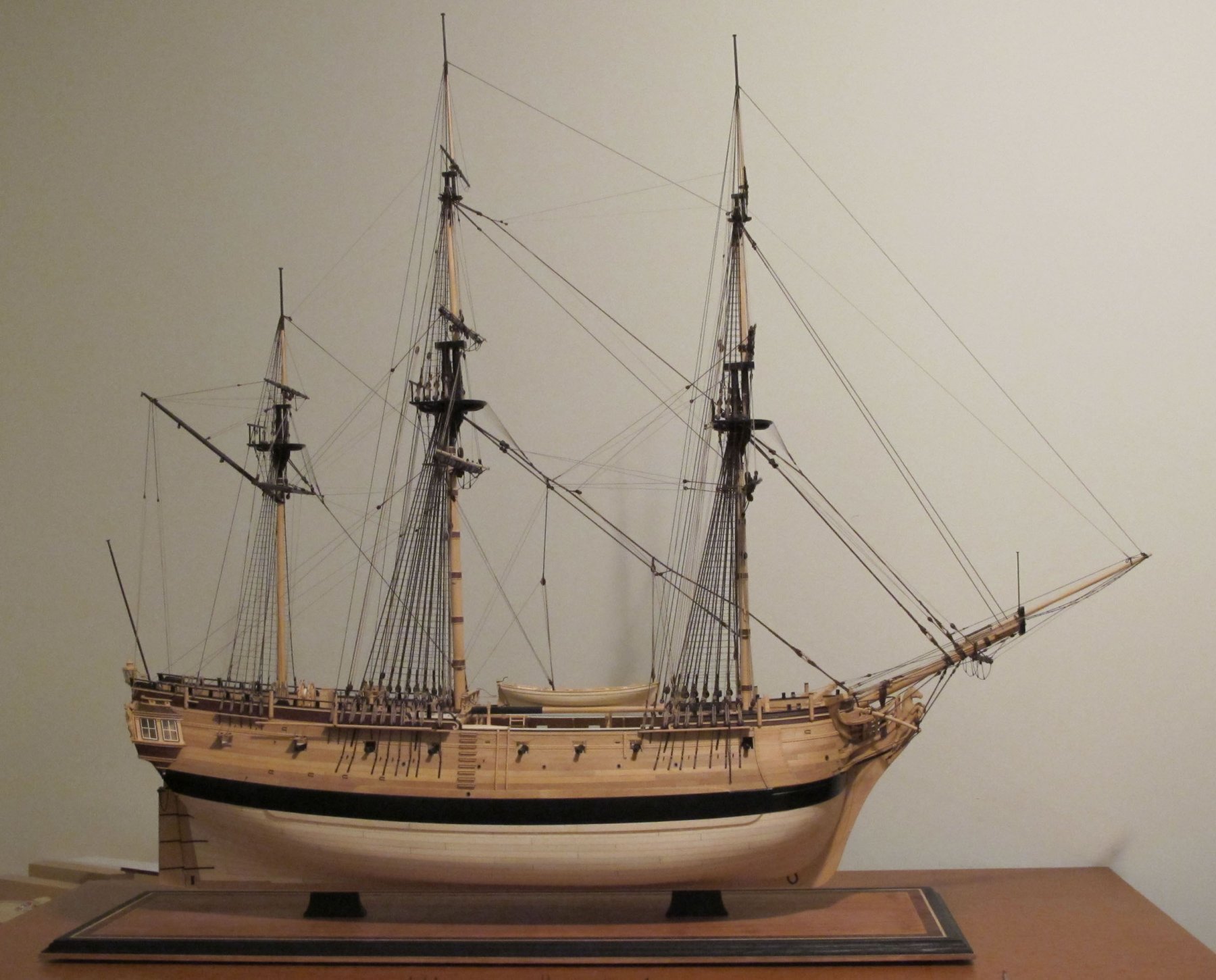
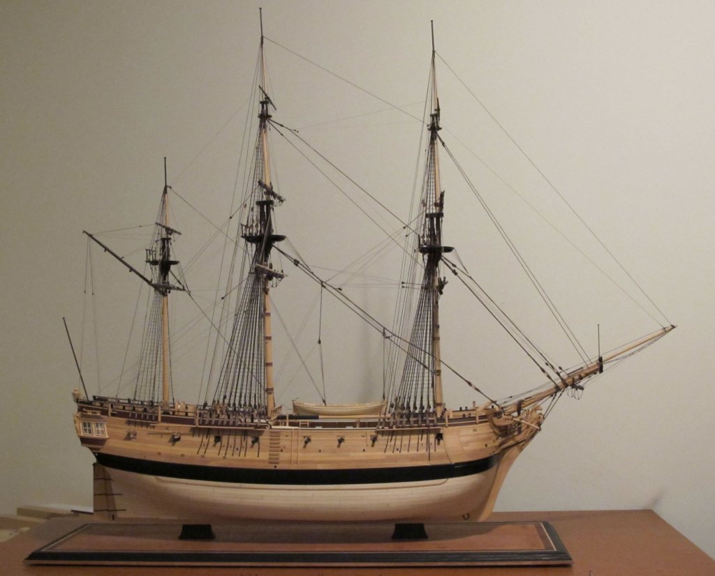
That 'thickened plank' you see under and on the wale was additional girdling that was applied to Resolution when she was fitted for the Navy in 1772-3. Even though she was a boxy collier, I suppose a question of her stability arose. You can see this feature better in the starboard broadside view.
-
Well re-cycled, Keith. I shuddered at your description of running the lathe at 200rpm to start off with!
-
Viele grusse, Barbara! That is a bitter-sweet story. I'm delighted that you are helping to complete the rigging on your father's model. To be honest, most of us need time to figure out the complex rigging from this era. The work that your father did on the hull etc., is beautifully done and the completed model will be a family heirloom, I'm sure. He is very fortunate in his choice of daughter!
-
Excellent news, E&T! Too bad they did not establish authorship before they went ahead. Hopefully, they will on another occasion.
- 346 replies
-
- 9
-
-
- terror
- polar exploration
- (and 2 more)
-
I'm sorry. After an extensive search on the internet, the only version of the photograph you describe is of such low resolution that I cannot make out any detail whatsoever. If you have a friend with a computer who can find a version of this with clear detail, perhaps he/she could post this here for us to look at. Otherwise, I don't think we can be of help to you.
-
Thank you, Mark. Hopefully the question is now resolved and that you will get a nicely faired result as well. BTW, you almost fooled me with your draught (above): at first I thought I was looking at a contemporary drawing! Very neatly done.
-
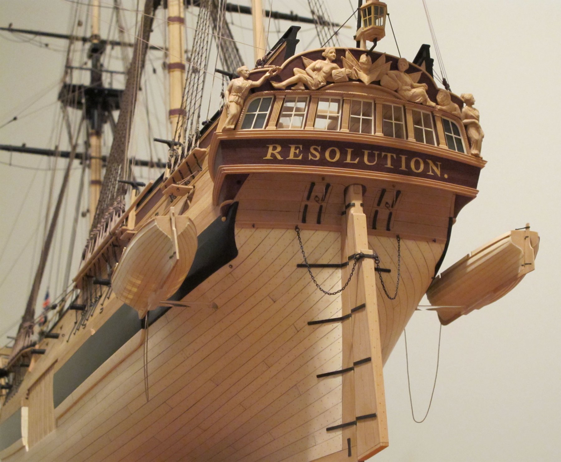
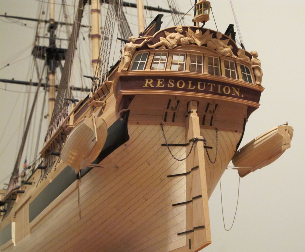
Thank you, Mark and Mark. (This is getting confusing!) The sketch just above reflects exactly the route I took with Polyphemus. It worked out nicely. As Resolution was a much 'boxier' shape, two pieces were required to fill the triangular gap, as shown.
-
I agree, Mark P. However, my question is; is this a separate piece of bottom plank, or shaped from the aft end of that wale plank?