


rlb
-
Posts
651 -
Joined
-
Last visited
Content Type
Profiles
Forums
Gallery
Events
Posts posted by rlb
-
-
-
Thank you everyone for your comments, likes, and just looking in. I appreciate the encouragement and support!
Whether it be the moon, the odiferous vinegar stain solution, or hunkering down from the bitter cold in upstate New York, work on the cutter is still at a standstill.
I look at it every day, however, and I hope to be back at it soon.
Ron
-
Thanks, Sam.
I'm at a bit of a standstill on the cutter, regarding the gunwale. Along with figuring out exactly which parts to stain black (all, or some combination of the gunwale, breasthook, stern angles, washboards, and oarlock supports), and how to glue and stain that assembly prior to gluing it to the hull shell, I also had to wait a bit for part A of my staining solution to ripen. (Steel wool needs some time to disintegrate in vinegar.) The result of this combination of a forced wait, and mental challenge, was a loss of inertia. I haven't "powered" through this little phase yet, but I hope to soon.
Ron
-
Bob,
There are three versions of Oneida in the completed ship gallery. Elia's is the truest to the kit, and Clay's (cfn1803) is started from the kit, with substantial alterations. There is also a scratchbuilt Oneida, by shipmodel, at a smaller scale), and I have my version in the kit build log forum (the link is in my signature).
I don't know why the search doesn't work well in the gallery. The two Lumberyard Oneidas are on page 16 of the kit built gallery (alphabetical as "US Brig Oneida"), and shipmodel's scratch Oneida is on page 4 of the scratch gallery.
Good luck, and I'll be happy to help any way I can, just send me a PM, or better yet start a build log and you'll get all the help you need!
Regards,
Ron
-
Remco, you never cease to amaze. It's hard for me to wrap my head around the tiny masonry you've done, and the handles on those pots are what makes them great.
Ron
-
-
-
Thanks, Keith, and Martin, for your comments--you're right, the admiration and inspiration we get (not to mention knowledge gained) from those who work at the highest level is often what drives us to do more, and better, than we ever could on our own.
Today's minor update:
As much as I've rhapsodized about the joys of my little cutter, I'm also feeling a little burnt out! I didn't spend very much time on it today.
But I did decide that it would be better to do the gunwales before the thwarts, just in case I need "elbow room" while gluing the gunwales on, without the thwarts in the way. (I do try, at least sometimes, to think ahead!) In anticipation of that work, I also determined that the apron at the stem needed to be cut down from where I initially had it--

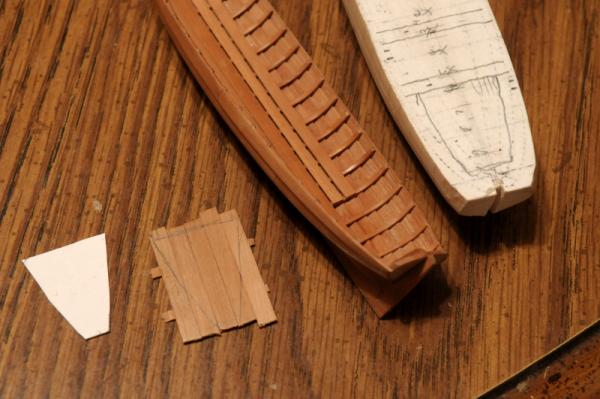
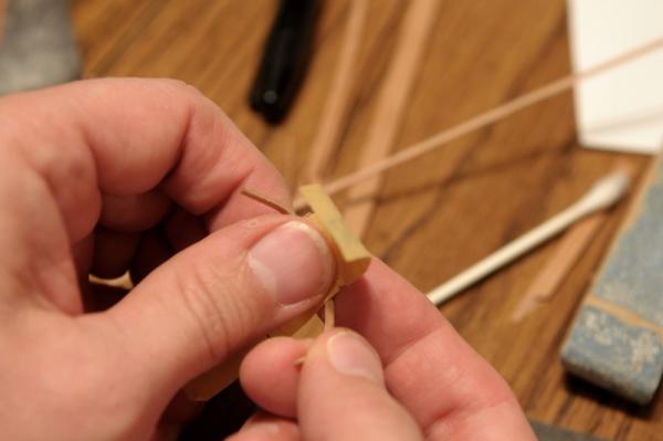
The gunwales need to be 1 1/2 inches thick, by two inches wide. Using my rotary tool "thickness sander" I roughly sanded some stock down to approximately 1/16th inch square (about 3" x 3" in scale), wet and heated it, to set the curve. The piece on the left I have started sanding down to final thickness--
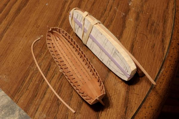
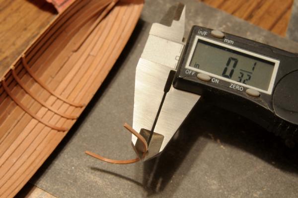
The next photo shows the difference between the rough form, and final thickness. There's also a pretty significant kink in the curve of the un-sanded piece, but I think it will disappear by the time it gets down to its final dimensions. In the background you can see I also had to re-glue the starboard rising piece. It had come loose on some of the frames. This is not a good thing--some earlier varnishing of the interior may have compromised the gluing integrity on the frames--
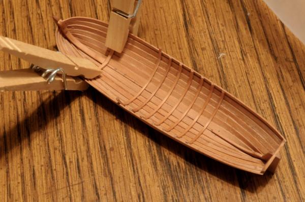
I think I am going to stain the gunwale black. I'll do this before I glue them on. The other pieces that attach to the gunwale--the breasthook, and a piece and some angles at the transom-- willI also be stained, but not the washboard. The port gunwale has been sanded to the correct thickness, but not yet the width. The starboard is still rough--

And that's it for now.
Ron
- JPett, WackoWolf, themadchemist and 12 others
-
 15
15
-
Thanks, Elia. The spacers were just glued to the top edge of the hull, very little was actually holding them there. After the rising piece was set, it was very easy to just pop them off again, and touch up the edge with some sandpaper. Ron
-
Yes it's amazing and humbling to see what the "professionals" can do. It's an awfully high bar to measure up to, and just a little depressing to think one is not likely to ever achieve that level.
On the other hand, the other night I think I spent about an hour just turning this little boat over in my hand, running my thumb along the frames on the interior; enjoying the feeling of having turned some small pieces of wood (have you ever stopped to think about how many pieces!?), into such an intricate, beautiful little form. That's a wonderful thing, even if it's not perfect!
Little was done today, though.
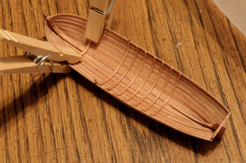
The temporary spacers were glued to the hull--
The rising pieces were glued to the frames--


Then the spacers were removed--
Ron
-
Thanks, Russ, Keith, and the Likes.
Keith, regarding your question, the short answer is: I don't know.
Long answer: I'm still confused on the nomenclature of all these boats (barge, launch, pinnace, longboat, cutter, deal cutter, gig, jollyboat, shallop, yawl, wherry). If I took some more time on research I might be able to learn more, but I've concentrated on just finding a suitable "cutter" to pattern mine on, and running with it. Even under the generic name cutter, I've seen some with gratings for the platform, some with "solid" platforms, some with spaced boards. With the forward platform, there are also many variations in configuration.
Now, here is a collection of ship's boats that puts my clumsy (in comparison) work to shame:
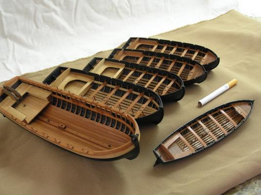
These are the boats for the 74 gun ship Rivoli, modeled by Doctor Michael. (and Keith, I'm pretty sure that's ebony
 ). Link to the source of the picture- http://forum.modelsworld.ru/topic8019.html where you can see more photos of the boats, and the whole stunning ship.
My cutter will end up looking (in configuration only!) most like the middle one in the row of five, and the second one in on the left, which looks about the same, just bigger. Those two appear to have a similar hull shape to mine, though my boat is smaller, and my oars will be single banked instead of double banked. Mine will also be stepped for one mast instead of two.
One point I saw interesting--these all have posts under the thwarts, which I'm not used to seeing. Maybe being double banked (with two crew per thwart) the posts were necessary, but on smaller single banked boats they were not?
Ron
-
Dan,
I can tell from just a few photos that you've already taken this wreck up quite a few notches. Cudos to you for sticking with your commitment.
At the risk of seeming uncaring (which I have the feeling you are NOT), I would probably be thinking of balancing my efforts with your friends' expectations--in other words, what seems only mediocre to you, might be fabulous to them. But knowing your standards, I bet it's very difficult to do a sub-par (to you) job.
Wishing you a good and speedy outcome,
Ron
-
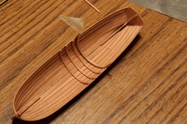
Continuing work on the cutter
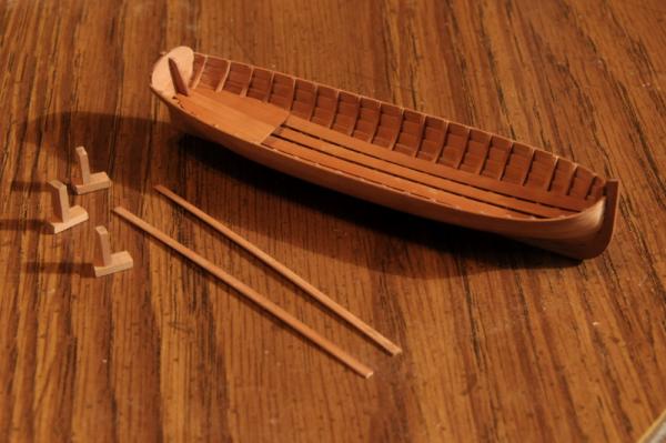
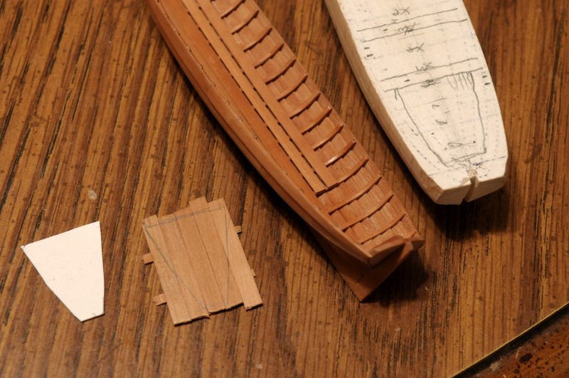
After installing the footwaling, the aft platform needed to be cut and installed. This was made as a "solid" platform. I cut a guide out of card and used it to trace the rough shape--
This was sanded until it fit reasonably well--
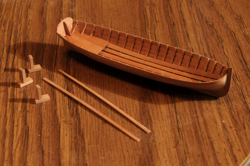
Unfortunately, the platform didn't sit low enough. Furthermore, and after looking at other model photos, I concluded that the "filler" piece I had put between the platform and the footwaling was a figment of my imagination (but wouldn't it be good to have something there to keep things from rolling under the platform and getting lost?). The best way to get the platform to sit lower was to notch it around the hull framing, and also notch the upper piece of footwaling. So, along with removing the filler piece, this I did--
The underside of the platform is not pretty or correct, but that doesn't matter--
Looking at these posted photos, the difference in elevation of the platform is hard to see, but it is actually significant, at this scale and detail level.
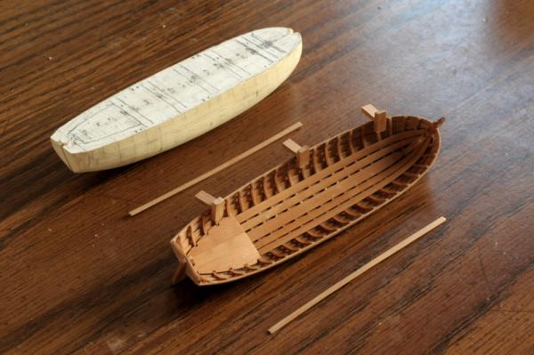
I've put a coat of finish on the platform, footwaling, and interior framing, and the next step will be to install the rising pieces--they support the thwarts. To the left are some spacing jigs that I made to help me get the risings placed correctly--
Ron
- mtaylor, themadchemist, CiscoH and 9 others
-
12
-
Remco,
Interesting! Could that possibly say "Steam Funnel"? on the deck right above the galley? Since this is on a lower deck than usual, maybe there was some apparatus (besides just a hatch grating) to disperse cooking steam as well as, and separate from, the chimney which took care of combustion gases?
My other observation is that I believe the typical "Brodie" stove needed access all around. That makes me wonder what the U shaped object is, which is backed up to a bulkhead. And what is the object on the deck directly above it.
Cheers,
Ron
- Elia and harvey1847
-
2
-
Thank you all very much for your comments!
Snow and bitter cold in upstate New York today. So I stayed home from work.
Most of the morning I spent researching; trying to come to grips with many details of the cutter. Chapelle's plan gave me the hull shape, but little else. I looked at some ships' boat models on the Russian forum, which were very helpful; and I went through the plans available on the NMM. I came back to an 1808 22' cutter that had very similar lines to (though significantly broader, and a little longer than) mine. There was a lot of detail on this plan to fill in the blanks, and I think it will adapt fairly easily to my somewhat shorter hull.
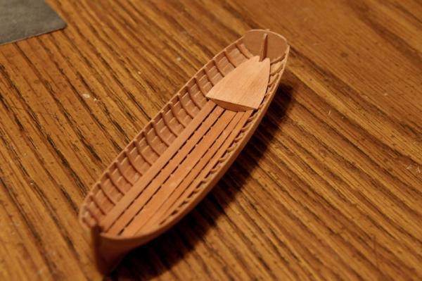
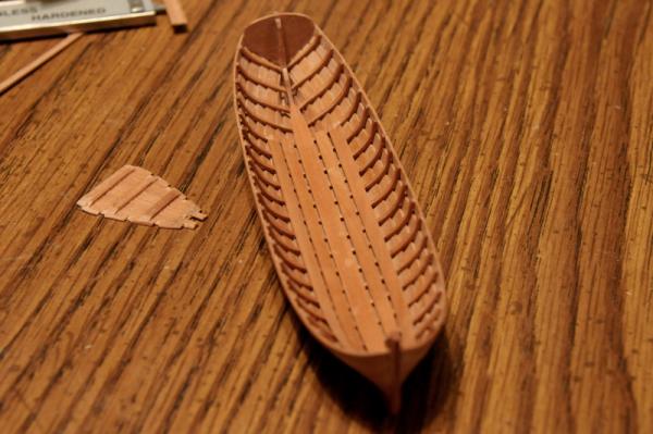
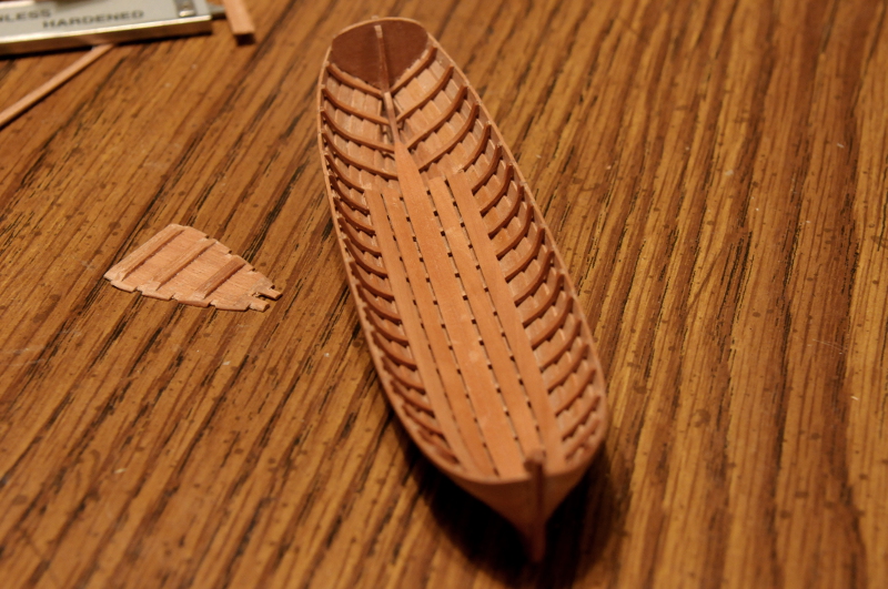
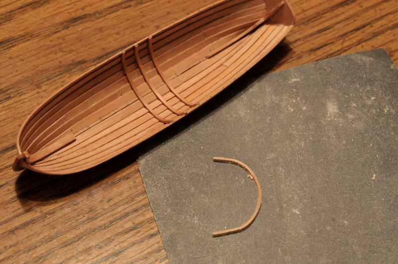
I made the keelson, glued that in place, then started with the foot boards. I figured I could end these just past where the aft platform will be, but I wasn't sure how far forward to take them. Some boats on the Russian forum took them all the way to the stem, so I copied this. I glued some temporary spacers, and a dab of glue on each frame--
First pair of foot boards in place. On top of the plug I sketched the plan of the thwart locations. The bow area is still a little unresolved, but this will be the general scheme of things. I had assumed there needed to be an even number of oars (if single banked), but the NMM draft for the 22 foot cutter showed 5 single banked oars. I guess the three rowers on the starboard side don't need to work as hard!

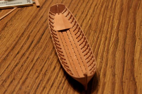
Another pair of footboards, and the footwaling is done--
Taking a break now to post this, and plan the next steps.
Ron
-
Your secret is safe with me, John!
I'm looking forward to seeing the frames on the keel. Those frames on the left seem very shallow compared to the others, but in your photos of the ship, the sheer didn't seem to be very extreme. Are they the frames that sit on the deadwood "steps"?
Ron
-
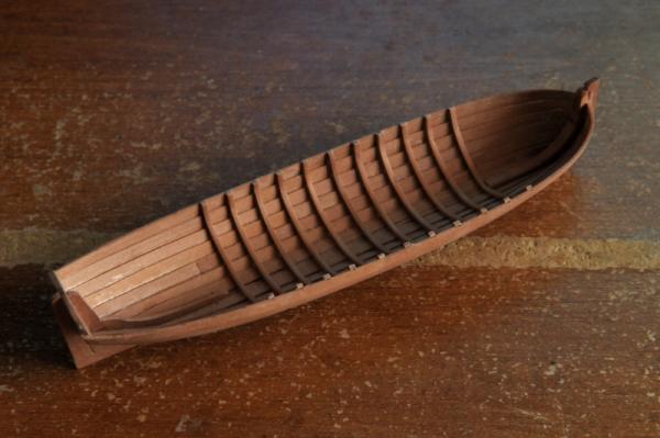
Thank you all, for your support and kind words.
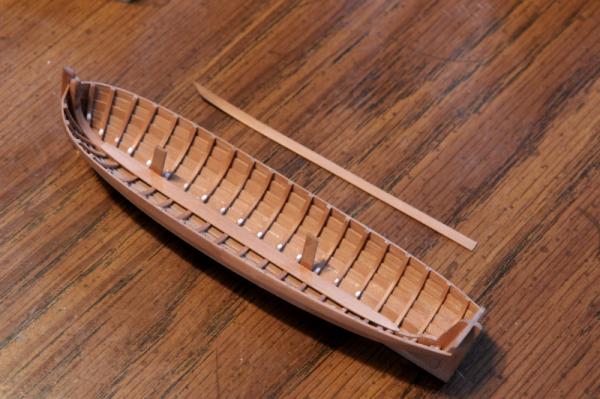
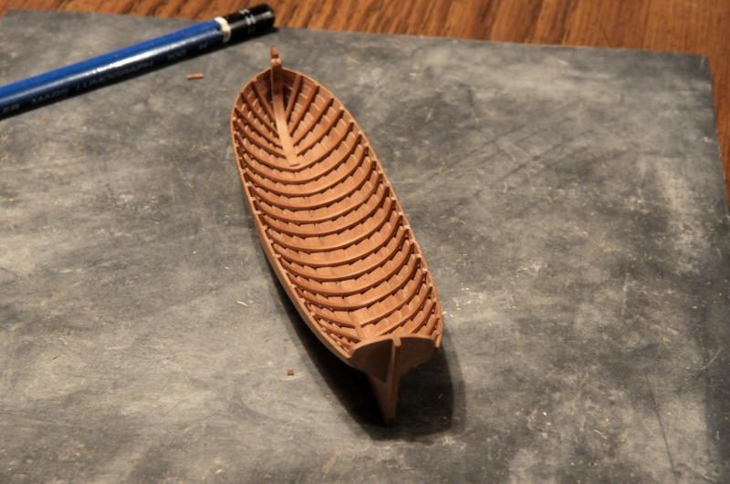
I challenged myself that I wouldn't make another post until I finished the frames. I didn't think this was very much of a challenge, as I thought it would be four or five hours work to do the half frames. Now it is ten hours later (where does the time go?) and I can report progress.
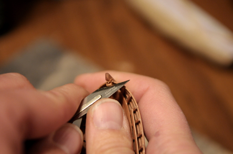
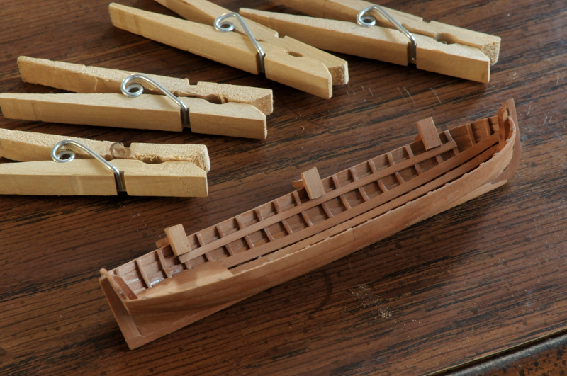
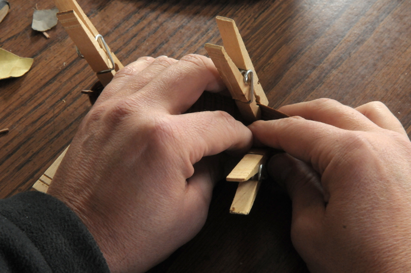
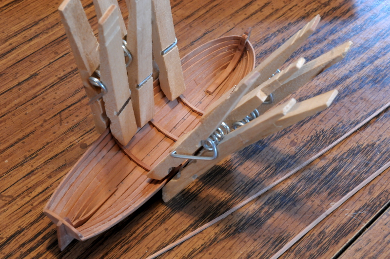
I spent much of the day in this situation--

Some frames, having been wet and heated, are clamped to set the curvature, while I hold a freshly glued frame in place with my fingers until the glue sets. The boat is in there, somewhere.
Here, the last two frames are clamped to set the curve--

I dropped the boat onto my wood floor twice. The second time I had four clothespins attached, and I was sure some planking would spring loose, but there were no ill effects.
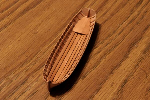
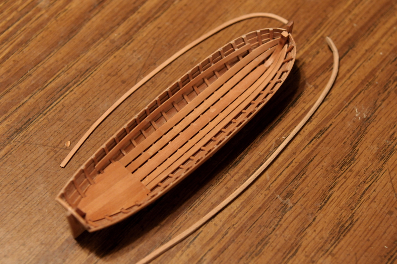
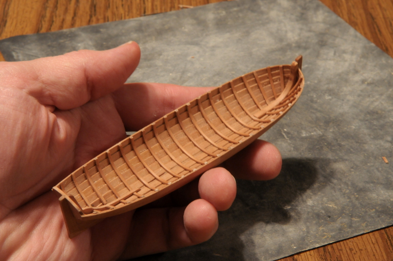
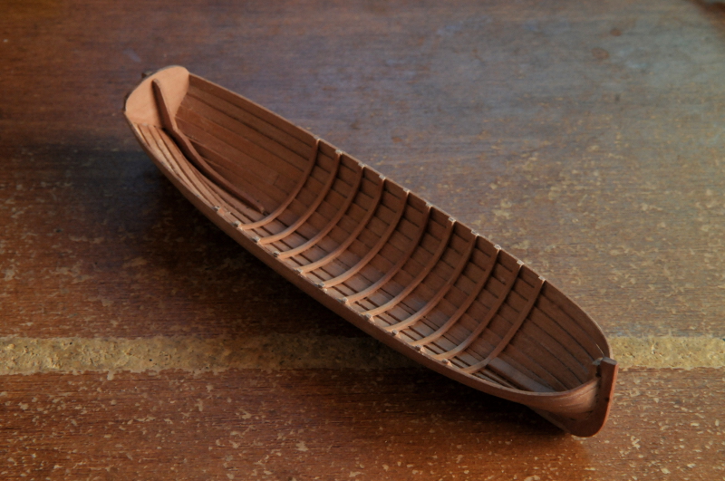
Now all frames are done. I think. There are a few that draw my eye due to uneven placement. I don't know yet whether I will adjust them.
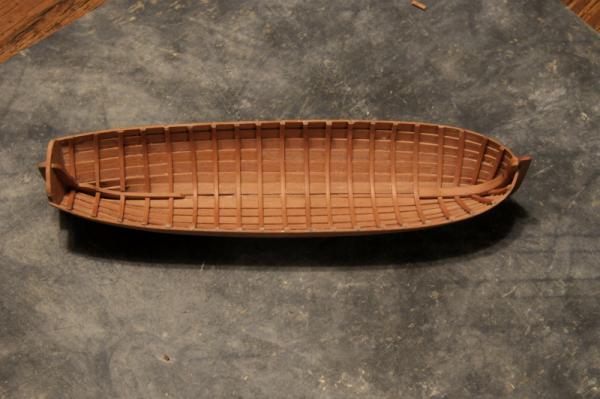
In this view they look more uniform--
There is still quite a lot to do on this boat--

Cheers,
Ron
-
Tom,
Great job on your Bounty Launch! I look forward to following your work on the Constitution.
Cheers,
Ron
-
Thanks, John!
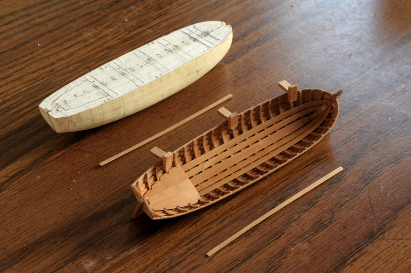
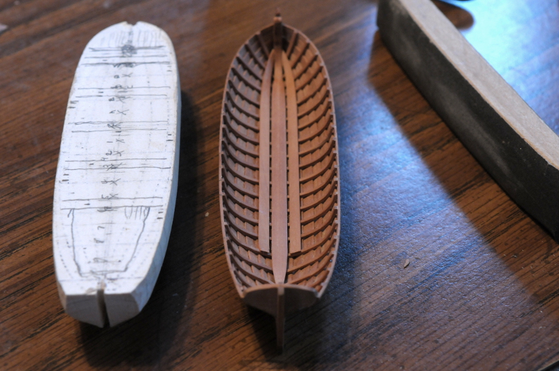
Here I have all but one of the full frames bent and labeled. As I did each one I marked a small "x" on the top of the plug to help me remember which I had done as I went along--
A comparison between a rough frame and a sanded frame--
A few of the frames glued in, and another unfinished frame for comparison--
Carefully sanding a frame, first on the inside, for smoothness. 220, then 320, then 600 grit--
Then scrubbing on flat sandpaper for the sided dimension, 220, then 600. I ended up leaving the frames about 3/64 inch wide--

Then the outside (the face to be glued to the planks) was sanded with a small strip of 150 grit sandpaper to reduce the frame to a final thickness of 1/32 inch--
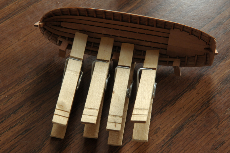
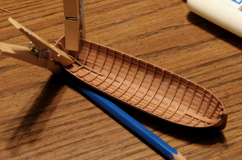
Then the frame can be glued into place. The clothespins are holding the "pre-bend" of last full frame as it dries. The frame just glued in hasn't had it's ends trimmed yet--
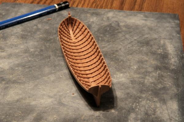
Current progress with all the full frames glued in--
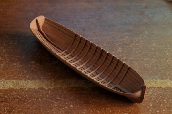
Ron
-
Thank you very much, Michael. Best wishes for a happy new year to you and yours!
Current activity in the workshop:
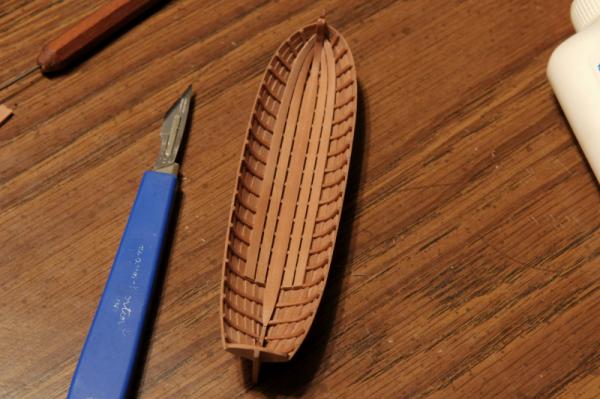
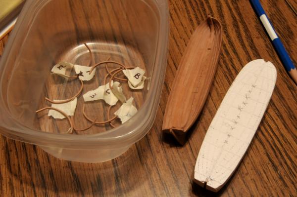
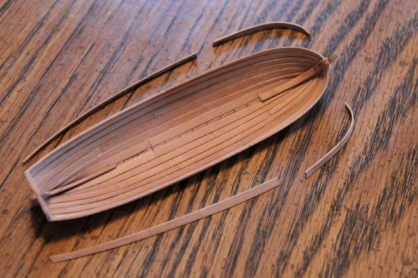
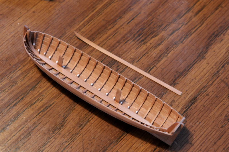
Removed the last strake of planking. I might be able to reuse this, or some of it, for the washboard. My pencil marks on the keel for the frame locations, every 12 inches in scale, are visible--
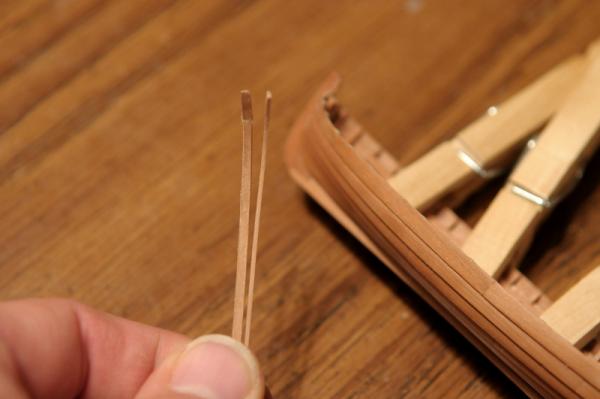
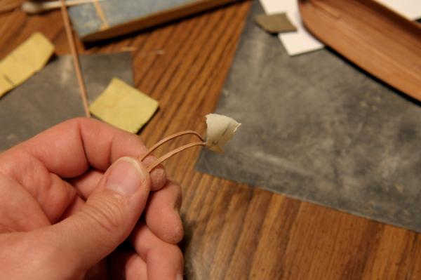
Wetting and clamping the frames in to set the curve. After immersing a length of frame stock in boiling water for 20 to 30 seconds, I slowly bend it around the plug. After that's successfully done (I've lost some material because the wood sometimes doesn't hold together around the sharper curves), I cut the frame piece from the longer length, and transfer it to the hull shell. Dealing with my fingers and the clothes pins, I can only place a few of these at a time----

Since wetting the wood expands the grain, (and it doesn't shrink back completely, or smoothly, when dry), I've cut these a little full. When dry I'll need to sand them down to about 1/32 inch square--1 1/2 inch in scale, before gluing them in.
Ron
- hexnut, CiscoH, Elmer Cornish and 8 others
-
11
-
Nice.
A next door neighbor, when I was 4 or 5 years old (about 1965), raced hydroplanes, and some of my earliest memories are of a kind of scary light (welding?) coming through my window at night, as he worked on his boats; and the trailer in his driveway with a stack of those strange shaped craft.
I look forward to your model.
Ron
-
Best wishes to you, also, B.E. for a great 2014.
You know you must throw yourself into the Pinnace. Your Pegasus is too good for second-best. (Though as I write that, I am trying to imagine the difficulty of building my cutter at an even smaller scale.)
Ron
-
Thanks, all, for the comments, and everyone who popped in with a "like". They are all very much appreciated.
Elia, I too, was intimidated by the clinker planking, but as with most of these modeling-things-one-hasn't-done-yet, the bark is worse than the bite. And, the other fact of model building--I think I can do it better next time!
I'm looking again at the Chapelle drawing, trying to determine all the details he didn't include in the drawing: footboards, platforms, seats, etc. Even the number of oars to account for is a mystery to me. How many would a 20 foot cutter have, two on each side, three, four? (My compulsive lack of planning ahead is evident, once again.)
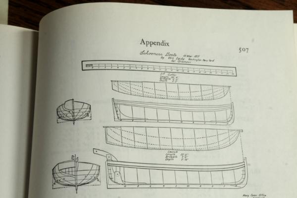
I think I have planked one strake too many. Chapelle didn't label a washboard on this drawing (I'm building the upper boat), as he did on many of his other cutter plans (nor did he dash them in as the Royal Navy plans do), and I was going to cap my boat with a thin gunwale, and thole pins or wooden oarlocks. But as I re-examine this, studying how he drew the transom on this and other plans, and taking into account the depth of hull measurement, I now think his drawing does show a washboard, which means I'll have to do some back-stepping.
I'll also go back through my W.E May book "The Boats of Men-of-War" for some clues.
Ron
- CiscoH, themadchemist, BETAQDAVE and 1 other
-
4
-


US Brig Oneida 1809 by rlb - The Lumberyard - 1:48 scale - POF - Lake Ontario Warship
in - Kit build logs for subjects built from 1801 - 1850
Posted
Hello all,
Once again, I've had a substantial lull in progress. I have replaced images in the more recent part of my log that went AWOL. I hope to start advancing work on the cutter, soon.
Ron