

catopower
-
Posts
1,772 -
Joined
-
Last visited
Content Type
Profiles
Forums
Gallery
Events
Posts posted by catopower
-
-
Thanks Druxey. I don't know if it's GOOD planning, but it is certainly some kind of planning. I guess I'll find out how good it is when I try to fit the box structure into place.
I have a sense now that there will be a slight issue with that aft deck frame or platform I made, because it is pushed up at a greater angle, now that the great beam is underneath it. On the actual museum model, if you look at the last photo of it that I posted, the very end beams of that platform form the base for the aft "wall". In the kit, it provided aft platform doesn't really seem to do that. The platform is kind of separate from that "wall".
I'll have to play it all by ear later, but I'm hoping that I can somehow modify the bottom of the "wall" and the aft part of the platform, so that they merge together to a more complete joint. At this point, I don't imagine it will be difficult to modify the bottom of that aft "wall".
-
I'm making some slow progress now with the planking of the upper deck, as well as adding all the smaller beams to the lower hull.
Planking the upper deck is pretty straight forward, or at least it would be if I could leave well enough alone.
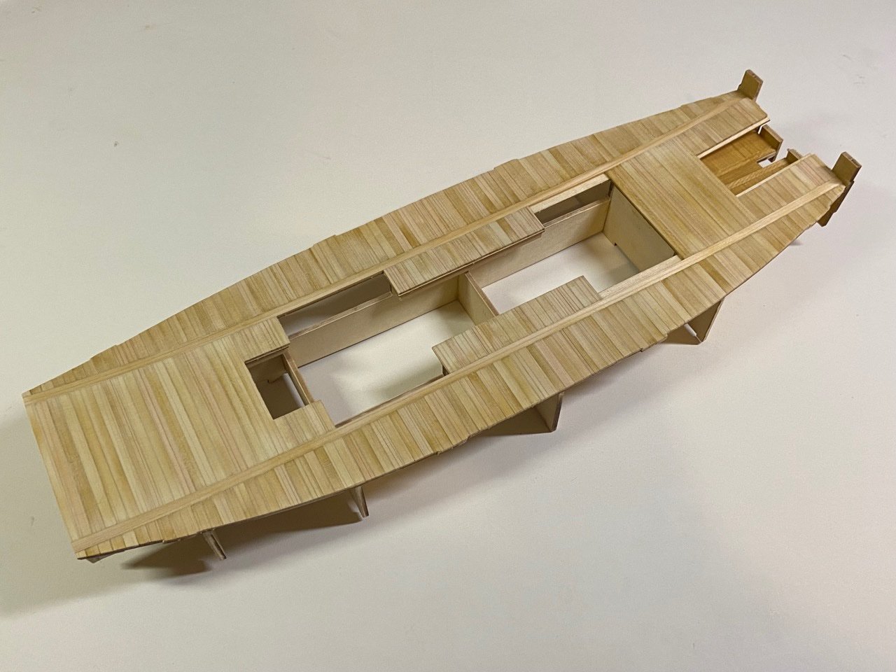
I've had to sand down the deck in order to smooth out the planking. The process too off the finish I'd applied, so I'll have to go over that again. You can see the difference when you look at the planked steering well area.
One thing I discovered while doing all the sanding was that some of the deck areas aren't well supported from underneath. It doesn't really affect the structure that much, as the planked deck is about 3mm thick. But, saning these areas results in these areas not getting the same degree of sanding as the rest of the deck, as the deck here was flexing a bit. So, I just put some reinforcing wood under these areas.
Meanwhile, I cut new pieces of the aft section of the lower hull, cutting out the old piecees to use as patterns. You can now finally see what I'm after.
I traced the openings of the original piece onto this one, so I could "map out" where the new beams need to go. The new "Ōtoko" or great beam is about twice the size of the one provided in the kit. This gives me more room to cut the rudder hole into it.
You can see also that this rear platform area is now above the beam and not below it. All of these changes will likely create some unforseen problems that I will have to deal with later, so I haven't glued any of this into place yet.
Lastly, I started adding all the smaller beams into place. The model nicely provides laser-cut notches in the hull for spacing these properly.
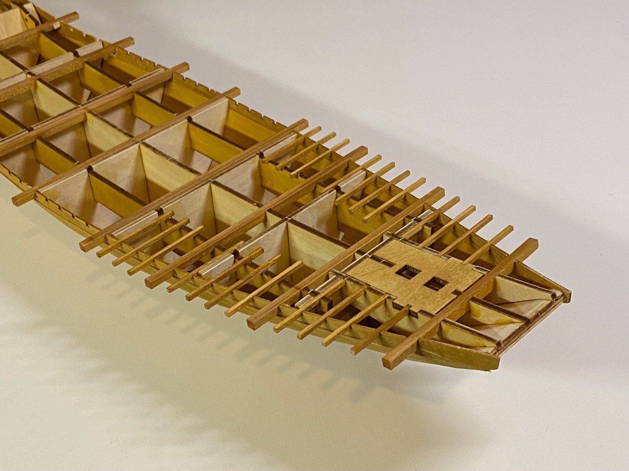
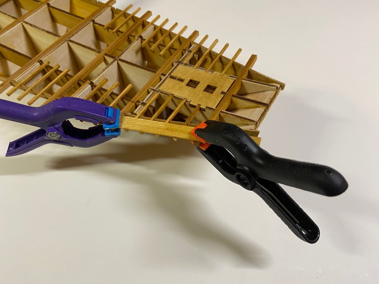
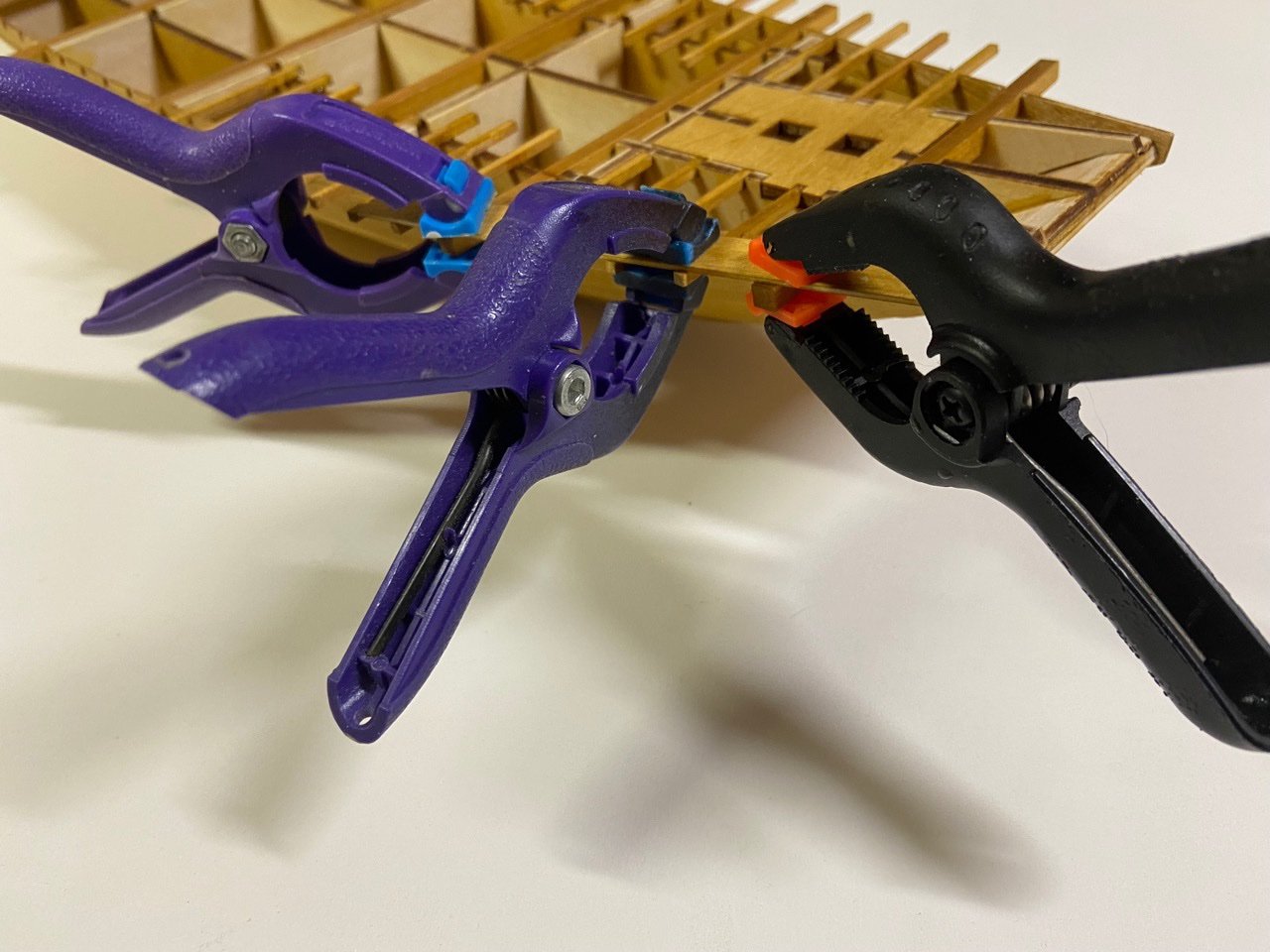
Inboard, the beams just rest on the internal framework, but they don't always rest nicely on the framework, so I had to use gap-filling CA on those. The important thing is that the outer ends of the beams need to be in a nice neat alignment with the ends of the larger beams. Also, the tops have be nice and level. To do this, I just used plastic clips and a piece of thin scrap wood as a guide
The beams closest to the bow have to be cut to the proper length before installing, but most don't need cutting right away as the inboard ends have no restrictions here. It turns out that the inner ends of some of the beams obstruct the placement of the box structure, so they do need to be clipped at some point.
Oh, I should mention that all the beams come as a set of pre-cut pieces. The large ones come from a laser-cut sheet. The small beams are simply pre-milled lumber. I don't recall if I mentioned it before, but the deck planks also come as pre-milled pieces in 3 lengths. Made planking the deck a relative breeze.
Once I finish with the beams, I'm going to leave the stern assembly unfinished until the box structure is further along, so I can test how everything will fit together. In the next few days, I should have the outer shell to the box structure started.
- GrandpaPhil, hollowneck, popeye2sea and 6 others
-
 9
9
-
Bug, I wonder if you two ever met? She was a Captain in the 441st MI Battalion, working in S3. She retired in '92 and then stayed on as a civilian up until she got transferred to Hawaii around 2012 or so.
Anyway, the build continues!
While contemplating the stern construction, I went ahead with the deck of the box structure. I took my time fitting the sub-deck into place since I made those modifications to the height of the internal framework, thus lowering the deck by about 1mm.
For this kit, Woody Joe has opted to provide 2mm thick planks for the deck. I suppose they are so thick, because the sub-deck they are glued to is pretty thin.
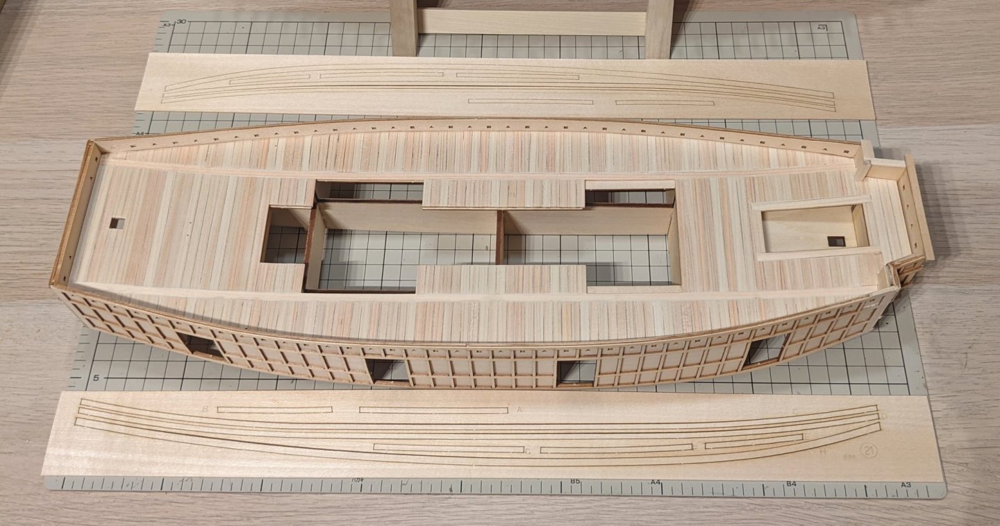
While deck planking mostly runs across the width of the ship, the first pieces to glue into place actually run the length of the ship. To make sure that these run correctly and fit well, I temporarily taped down some of the pieces provided that will have to fit in between them first.

After that, it was a rather quick matter to lay down the long fore-and-aft planks, and then the rest of the planking pieces.

Something interesting about this kit is that in order to simplify construction, Woody Joe milled the planks to three different lengths. Those long pieces in the middle were already cut, and I jus laid them into place. Below, you can see all three sizes of planks. I've had to do no cutting for any of this.

It wasn't long before I had the bow section done. Note that in order to keep the middle and outer planks aligned, the instructions show to start the planking from the edge of deck opening, working outward from there. Later, those plank ends that are sticking out over the edge of the deck will need to be trimmed.

By my next post, the deck will be planked and trimmed. I'm considering adding the outer shell next, before I return to the final decision on the stern section of the hull.
- druxey, mtaylor, hollowneck and 8 others
-
11
-
Roger,
Your comments are well stated, but nobody is arguing against quality in ship model kits, your standing in the NRG, or advertising vs quality. What I wrote was simply a comment about your anti-importer remarks. As if importers provide nothing.
But, you also have me thinking about your comment about ship model business being like any other business. It really isn't though, is it? Those who are really advancing kit design, I doubt they could make a living off of it. I think they're mostly subsidizing it because it's something they want to do. There just isn't the volume sales to do otherwise. They need a larger market, which is nearly impossible to do without advertising and all that you refer to as wasteful stuff. That's why they're often happy to have importers/distributors, because they get the products out in front of people and make larger quantity purchases, which gives the manufacturers a little needed cash infusion, so they can spend a little more time designing and less time shipping individual orders.
I'm just saying this because I'm always running across a lot of unnecessary bashing of kits, manufacturers, sellers. They have their place, even if it's not in your own workshop. And, I don't say this, just because I do some occasional work for an importer and know many people in the industry – I actually believe it.
Anyway, sorry to plug up the thread with this stuff, Kev! I'll go quietly...
-
Bug, that must have been nice. Tachikawa was the last piece of Japan my little feet walked as we left there when I was 3 and didn't return for about 40 years.
Meanwhile, my sister was at Zama for god knows how long. She managed to avoid getting transferred for an amazingly long time. That was fortunate for me, because she was still there when I finally got interested in visiting in 2006, so I had a place to stay.
- thibaultron, Canute, druxey and 5 others
-
8
-
On 10/16/2021 at 11:05 AM, Roger Pellett said:
A somewhat cynical view of finishes:
Kits are expensive: You are paying for someone else's intellectual property, which you should, but you are also paying a lot for marketing, and distribution. Each organization between you and the manufacturer needs to be paid.
To offset these marketing and distribution costs, many "Hobby Shop Grade Kits" do not use high grade materials, and many use misleading descriptions to promote sales. For example, genuine American Black Walnut is an excellent wood for high end furniture, but not so good for ship models, and the stuff marketed as walnut by some kit manufacturers is worse.
Trying to find a finish to enhance the appearance of low quality wood is a waste of time. Although there are finishes advertised to turn any wood into a work of art, these are aimed at the DIY and Craft markets. Many of these contain fillers intended to hide defects, thereby covering up detail that we want to show.
So, realizing that not everyone has unlimited resources to devote to this hobby what are the alternatives.
Deal directly with a kit manufacture with a reputation for furnishing high quality materials: By buying directly from the manufacture your money goes into the kit. You are not paying for distribution. Links to these quality kit manufacturers can be found here on MSW.
So, we should let those "wasteful" importers know that they should just shut down and stop paying money for those Journal ads and sponsoring MSW then? 🤔
-
Hi Harvey, I'm not sure when the museum model was made. But, to be clear, it's in the Saga Cultural Nagoya Castle Museum on Kyushu and not at the Nagoya Castle in Nagoya(!). I didn't even know about the first one until a few months ago.
As for my Atakebune model, I'm making small amounts of progress on it, specifically with the gluing down of the deck of the box structure. But, I haven't worked on the much in the past several days, while I've been dealing with work and life issues.
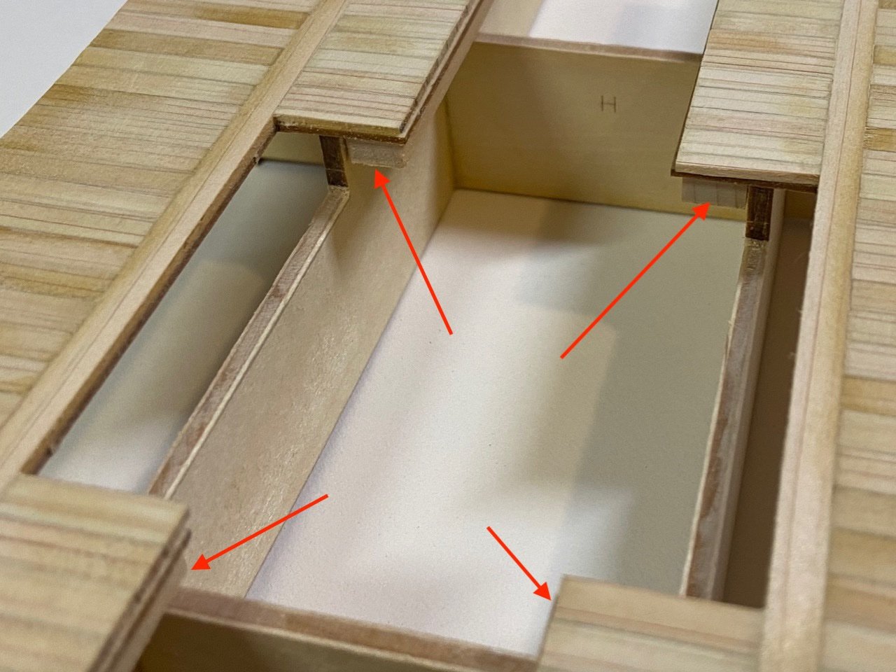
Meanwhile, I'm studying the stern area of the model and I keep thinking of ways to complicate the model in the name of making it look more accurate. There are a couple issues I'm seeing that I'd like to fix. One of them is the piece that fits into the stern area, where I've outlined in red below.
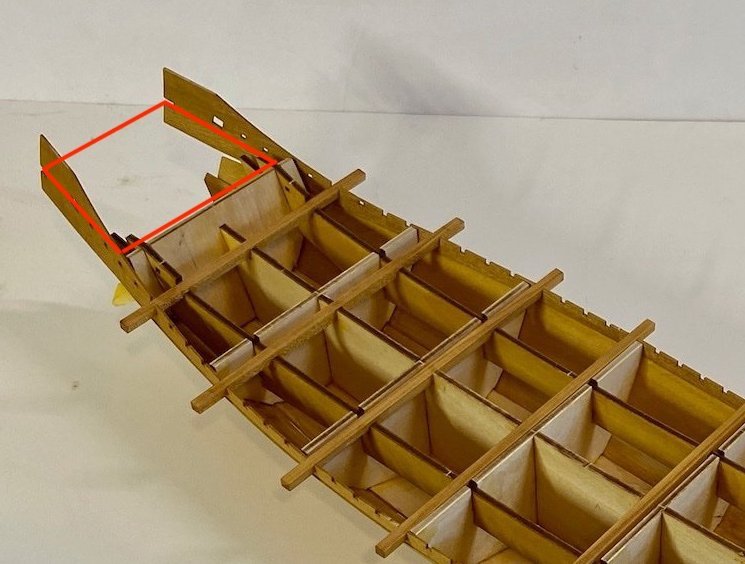
Below on the right, is the piece which was provided, which is fine. On the left is my idea of what this area should look more like. It's something of a compromise, since it needs to fit the other parts in the kit. This whole thing would be planked over on top.
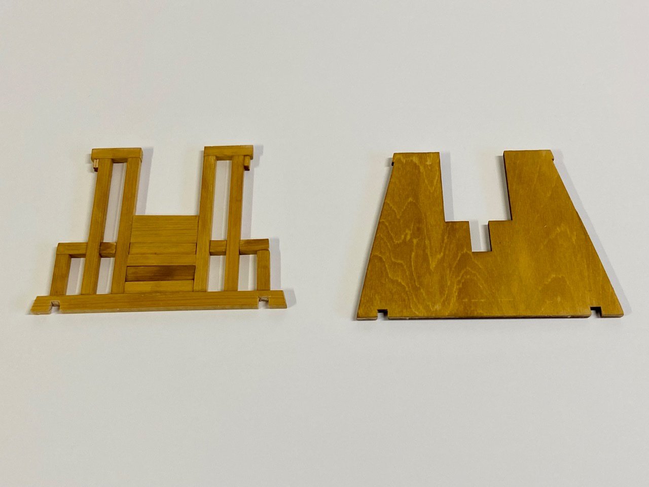
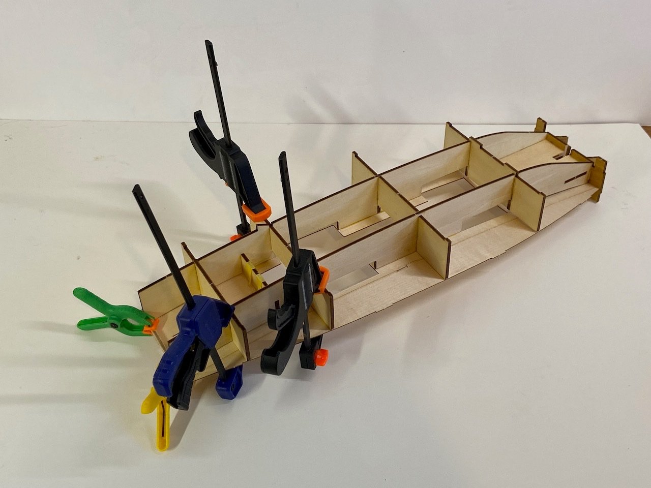
Test fitting this piece into place, you can also see below, the new, larger beam I made. Again, this is a bit of a compromise. And, there's a lot to explain here...
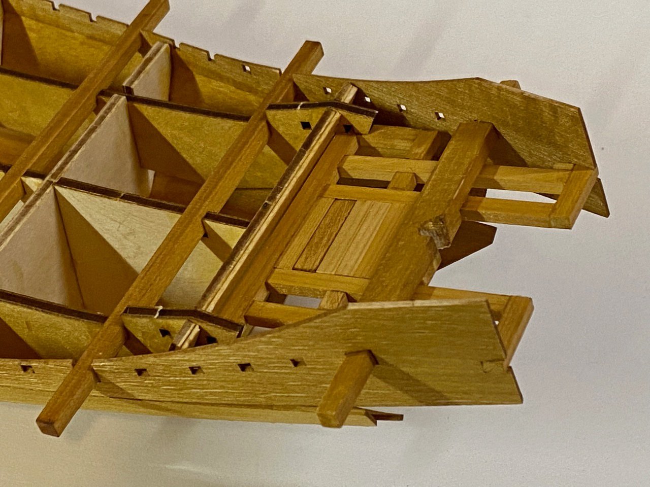
First off, that "plaform" should really be resting on top of this heavy beam. Woody Joe moved these aft beams up so they directly support the box structure. But, if you look at the museum model, you can see a kind of riser on top of the beams and under the box structure, designated by the green arrow.
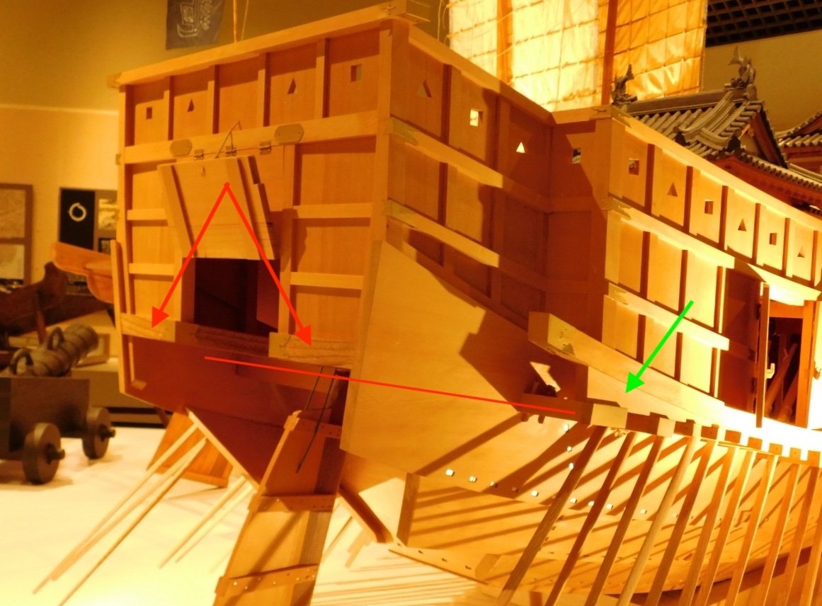
I also drew a red line following the heavy beam and note how the platform structure rests on it.
Also, the rudder is aft of the heavy beam, not in front of it, as provided in the kit. The main purpose of that heavy beam is to hold the rudder in place, and the rudder kind of rides it. The heavy beam should also be notched to receive the rudder, which should be held against it with a heavy rope.
Below is another comparison of the two stern parts, along with the heavy beams. On the left is all scratch and on the right are the kit parts.
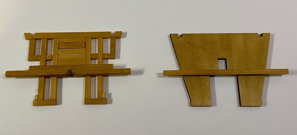
The kit (parts on the right) is supposed to have the rudder passing through that opening just above the heavy beam, but it should really be behind the beam (below, in the picture). So, my solution on the left, was to wide the main part of the beam to make room for the rounded notch.
Now, there are a lot of different options I could have taken, and my original thought was just to use the new beam with that old solid platform. Anyway, the platform should be planked over, and that would be very easy to do here, except that beams are made to ride directly on this platform, so the planking would have to allow for that. But, the same is true for my solution.
Still, my solution is a compromise, and I'm considering options. It's a compromise because that beam should really be underneath that platform. But, do to that, I'd need to remake at least a section of the hull planks.
And so, I kind of sit and ponder... But, again, this is my first of two kits, and I might just save such a modification for the second kit.
If I do make the modification, it basic means remaking the two pieces marked with arrow and cut about I marked the red line.
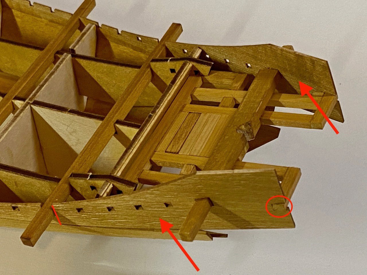
One benefit is that I could also get rid of that little assembly notch that I circled in red.
Back to pondering...
- popeye2sea, Ekis, hollowneck and 9 others
-
11
-
 1
1
-
Hi Moonbug, Glad to have you following along. What part of Japan were you in?
Druxey, in fact I have two regular contacts in the Rope, one of whom has helped me out a lot in the past. The funny thing is that he didn't know much about traditional Japanese boats until he started providing help for myself and a gentleman from France who was also researching Japanese boats at the same time. He's helped me so much, but mostly by contacting people in Japan for me, or investigating information I find and send to him. Just last year, he built what is probably my favorite Japanese boat model ever. It's a type of transport that was famous on Lake Biwa and was called a Marukobune.
Time for me to check in with him!
-
Hi John (Jim Lad), glad to see you here. There's a certain comfort in building a Woody Joe kit. I still have a stack of them, as well as other projects to finish up, but I was petitioning them to create this kit, I gotta give it lots of attention.
Druxey, that's the problem with this subject matter, particularly something that's so historical. I haven't met, in person or by email or Internet forum, a single person in North America that I've been able to really discuss this stuff with. Makes for a lonely existence, but an interesting one none the less.
On plank lengths, well, they didn't run the whole length of the ship. A good 4-5 meters of the length is the stem, so that reduces planks to maybe 85 feet or so. That may not help much for the Atakebune, as it doesn't have a protruding stem, and it's just under 50 meters long. 25 meter lengths are one thing, but 50?
I'm not going to be representing the plank length issue on my model, as it's really following Woody Joe's attempt to create a model of a model. However, I do have a second kit, and I'm thinking that, with it, I'll address the plank length in a manner like that of the model with the sail that I posted on Friday evening.
-
Hi Peter, Mark, thanks for chiming in.
Research is a challenge, but it forces me to be more creative about finding answers. In fact, I thought further about the question about the large planks, and realized that I know a contact in Japan who's a professor at the Gifu Prefectural Forest Culture Academy! Doh!
His english is very good, and I'm hoping he can tell me something about wood cutting in Sengoku period Japan.
My guess, and it's just that, is that trees were felled, split with axes and wedges, then a crew with adz (adzes, adzs?) work the cut piece into a flat board.
I hope to find out something in a few days. Keeping my fingers crossed that I'll get useful info... 🤞
In the meantime, I finally got the hull planking pretty well done. There's a little adjustment to do at the stern yet.
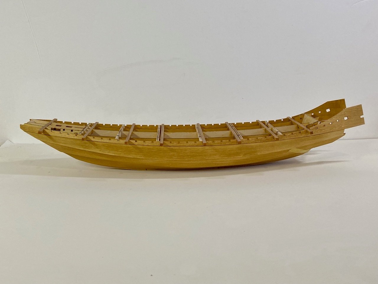
Next, there's a platform at the stern I need to decide on what to do with. Plus, there are 3 to 4 smaller beams between each of these large beams.
Meanwhile, I putting the deck on the box structure. I have to be very careful here, as I've been making some alterations. I have to make sure this doesn't mess up the addition of the structure's outer shell.
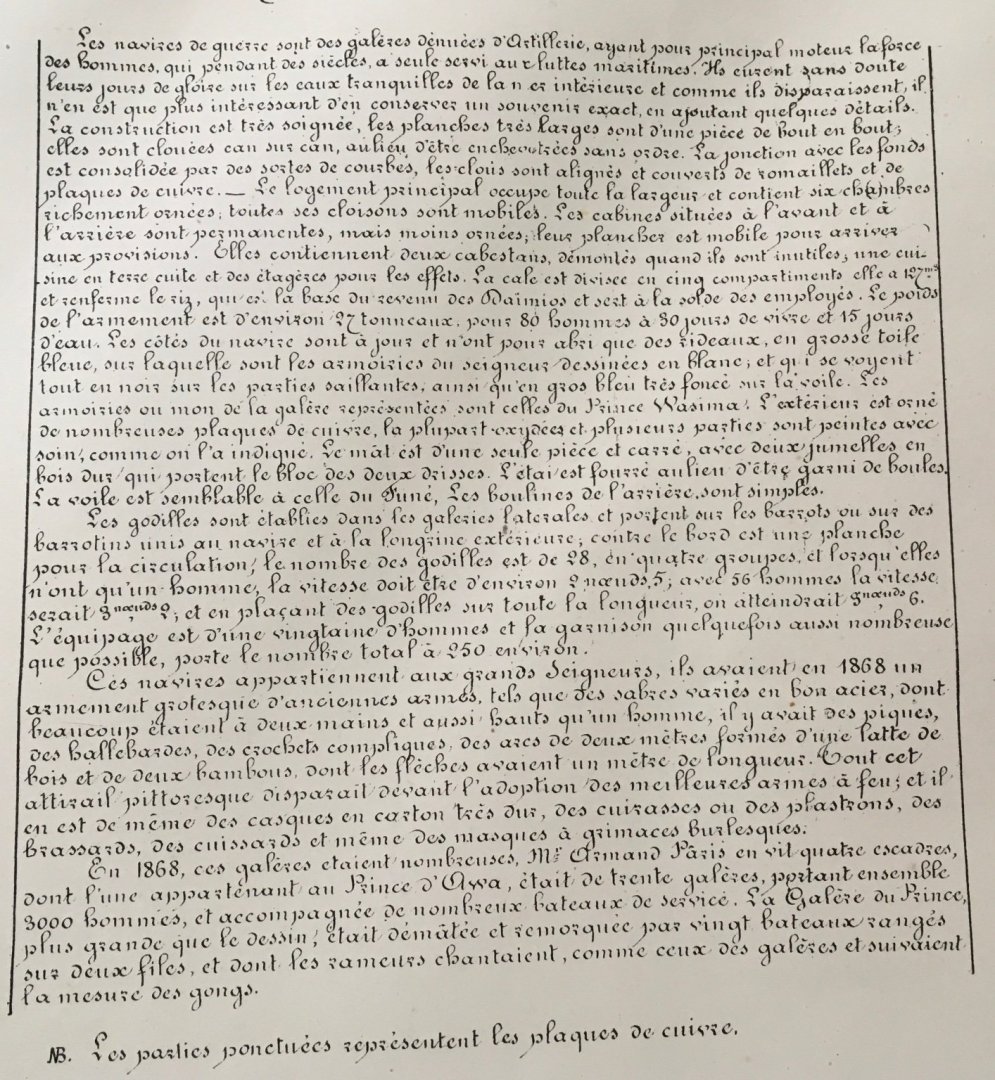
By the way, regarding that quote by Lt. Armand Paris on the planks of the Sekibune/Gozabune, what he refers to as a Galley, Here's the text in French script. If anyone can translate this, perhaps we'll discover that I've misquoted him regarding those plank lengths.
- thibaultron, Harvey Golden, druxey and 9 others
-
12
-
Hi Mark, Druxey, thanks very much for the comments. It's not much fun posting a project on MSW if there's no discussion at all.
5 hours ago, mtaylor said:Fascinating, Claire. Your build of these models and the history and "how they did it" shows a lot of research going on on your part.
Mark, I do like doing research. Probably more than the actual model building. But, it would be nice if it were a little bit easier for me to do. I just finished up an early Meiji-period (1868-1912) fishing boat from Souvenirs de Marine, and there are a couple features that I have questions about and few resources for answers. For the Atakebune, it's far worse, as there's so little recorded information dating that far back. Unlike in the west, the Japanese don't have a tradition of keeping ship building records.
I had to go to Japan to get as much info as I have on the coastal transports. There are none actually in existence. What there are are all reconstructions, using what was known about the ships. But, those ships were around in the era of photography, so there is some visual evidence of construction techniques. Plus, there were people who were familiar with their construction alive well into the 20th century. There are also LOTS of votive models of them made.
4 hours ago, druxey said:Interesting stuff, Claire! And already kit-bashing your model at this early stage.
I'm surprised at the Souvenirs statement that planks 30m long were one-piece. That's 100 feet, which seems unlikely.
Druxey, with this kit, I really needed to start planning the kit bashing before beginning. Also, I think to anyone who's been interested in the kit, the simplifications are fairly obvious, even if one has never seen the museum model it's based on. It's obviously been designed to be easy to build. But, that just leaves a lot of potential for the builder.
Regarding your comment about the unlikely length of the hull planks of the Sekibune, I'm glad you pointed that out because that is really one of the dilemmas I'm facing with these ships, and it's why I posted his comment.
We're all of the same western mindset that planks can't be that big. I mean, how could they be? How could they manipulate or cut wood and find trees that big? Yet, here's a French Naval Officer who was in Japan in 1868, who clearly had the skills to record the details of many Japanese boats he encountered, down to noting the thick boards and beams and how they were fastened together, etc., and he makes this statement that the planks were one piece, end-to-end. It does seem unlikely, but he had the knowledge to make that statement and include it with his drawings.
Obviously, I'm no expert, but I often feel that I am attempting to understand that which can not be understood...
- markjay, thibaultron, mtaylor and 4 others
-
7
-
On another thread, Ekis brought up an interesting point about these Woody Joe kits being light on detail and pointed out the issue of the large one-piece hull planks that appear on this model and even the original museum model. Now, I don't have any real answers here as to how the planking on these ships really was, but I have posted some thoughts on my blog that I thought I'd share here:
One thing that was brought up recently by a fellow ship modeler was the apparently simplistic representation of the hull planking on models of Japanese boats, particularly that of the larger ones like the Atakebune. The idea was that there's a desire on the part of western ship modelers for more detail, and that the large single sheet planks of the Atakebune kits hull wasn't exactly realistic. So, I've thought about this for a while.
It's true that Woody Joe kits lean towards easier construction, and trade-offs most certainly have been made regarding the inclusion of various details for lower cost of design work, materials, and easier assembly. This is true, to some degree, of any kit manufacturer. But, how were the hull planks really made up?
These large panels were certainly not made from one single sheet of wood, and must have been made up of various pieces fastened together. How large were the timbers that were available? How were they laid out to form these large panels? How were they joined together? How were the ends of timbers fastened together? Probably, nobody knows for sure. But, there are some examples we can follow, assuming that these are correct, or at least plausible.
One excellent example is to look at one of the replica coast transports that were built in the past few decades. While these are not Atakebune, the way they are constructed at least gives us something to possibly follow. The best example of these today is the Hakusanmaru, on Sado Island. This is the best preserved of the replica bezaisen, as the coastal transports were called.
I visited the ship in 2016 and took a lot of photos and tried to develop an understanding of the way these ships were built. The details of the structure is very complex, and what your seeing in these photos of the lower hull, is essentially a covering planking that hides and possibly protects the actual structural planking.
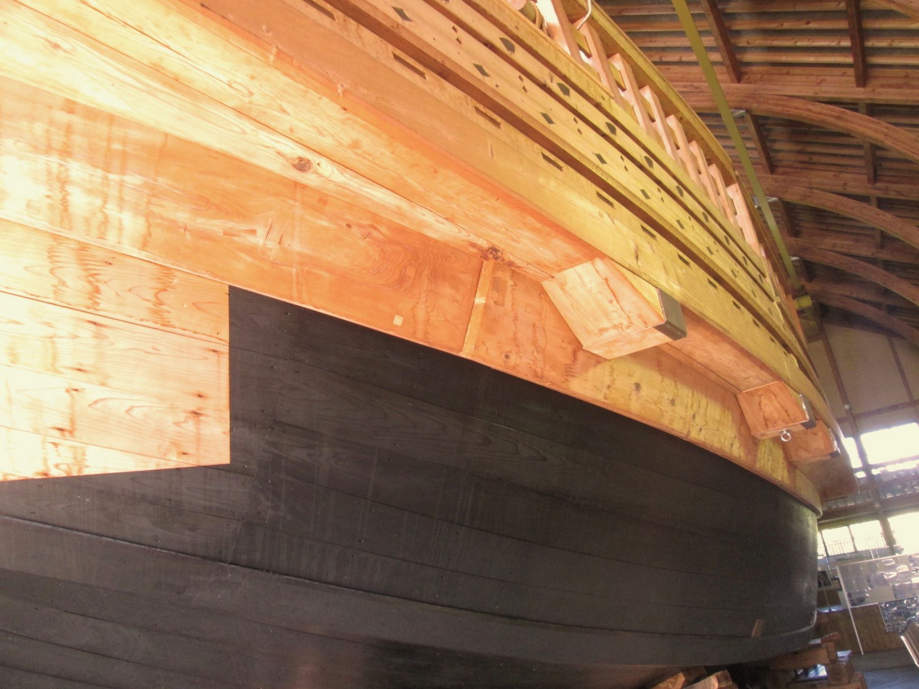
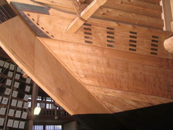
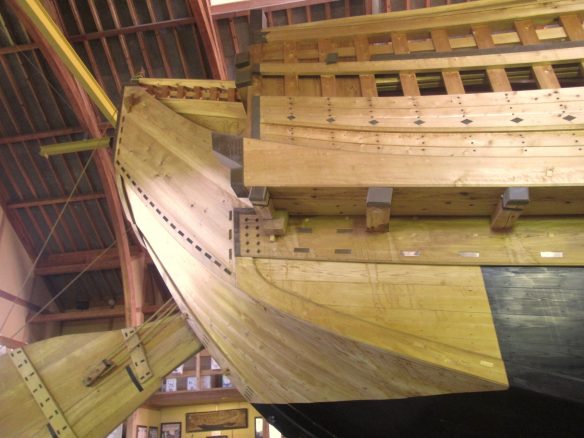
At the Hakusanmaru museum, there's a representation of the cross section of the hull which tells us a lot more about how the planks are fastened together, and the general scale of the wood that forms the main structure of the ship.


Again, this is a cutaway of the 25meter long bezaisen replica ship, not a 50meter long Atakebune. Their hull shapes, they are built for different purposes, and all. But, it gives you an idea of what a ship structure looks like with heavy planks and no frames.
As I pointed out earlier, this bezaisen had a kind of finish planking that was much lighter wood, and this hid these heavy iron nails. This kind of outer planking may or may not have been present on the Atakebune. And, probably, all Atakebune were different, and more prominent ones may have had a nicer finish. But, one things is clear. There are no scarf joints in these planks. There are overlapping joints in the structural planking. In the finish planking, there are simple butt joints, not staggered in any way.
But, the whole question of planking detail may be more complicated than it needs to be. As illustrated in the photos above, the Japanese shipwrights generally didn't caulk between planks the way their western counterparts did, except possibly at the chine, which are the sharp angle changes in the cross-section of the hull. So, there is little to show of the seam between adjacent planks.
In my own experience, I have scratch built models of Japanese boats where a wide board is made up of two edge-fastened planks, and the only way you can tell that there are two pieces is really because the difference in the grain and figuring of the wood is visible, but only barely, and that's at 1/10 scale. At any larger scale, the seam would be completely invisible.

My Hozugawa Ayubune model in 1/10 scale. The hull is made up of 2 planks on each side, and you can barely see any seam between the planks at this scale.
Now, the length of the boards may be another matter. It's doubtful that an Atakebune hull was made of continuous planks, in this case, 50-meters long. Looking at the paintings of the large Edo period Hiratabune, which were cargo riverboats, they were up to about 24 meters long. At this length, the painting shows the two overlapping joints in the hull planking, making each plank section about 8 meters long.
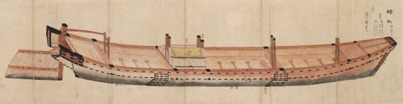
The Hiratabune was a 24 meter long Edo period cargo riverboat. Note the overlapping hull planks.
So, probably, on an Atakebune, there is likely some fastening and overlap of planks like that shown in the Hiratabune illustration above. On a large hull, assuming longer planks were used, the number of these overlaps are minimized. And at 10 meter long planks, on the 50 meter long Atakebune, there would be about 4 of these overlaps. Of course, there would be fewer if they could manage to use longer plank.
However, if the hull of the Atakebune was finished the way the Hakusanmaru is finished with a covering of thin, narrow planks covering any fastenings and any of these plank overlaps, then at 1/100 scale, you wouldn't reasonably be able to identify ANY planks at all, and it would look like one solid sheet of wood.

Saga Prefectural Nagoya Castle Museum model.
But, I suppose if you want to assume otherwise and want fastenings and planks to show, there's a great example in the model of an Atakebune called the Atakemaru. I found photos on Internet, and I'm sorry to say I don't know where they specifically came from. But, it's a beautiful model, and shows the large planking overlaps, and some finer planking detail. Is this accurate at all? I can't say for sure. Certainly, it looks nice. So, maybe some builders will want to try to modify this Woody Joe kit into something more like that.

Now, having said all that, I'll add something more that comes from Lt. Armand Paris in 1868 regarding a 30 meter long ceremonial yacht that is essentially a decoratively enhanced Sekibune warship, which is the next size down from the Atakebune. The Sekibune is like a cruiser in comparison to the Atakebune being like a battleship.
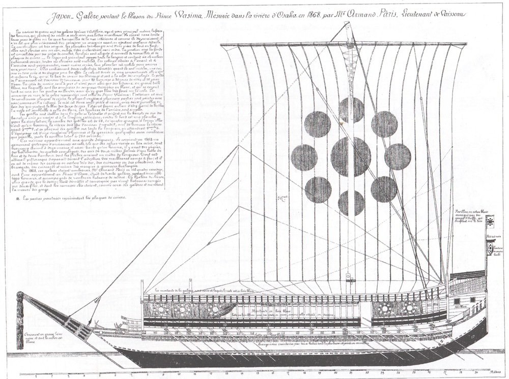
Paris describes "The construction is very neat, the very wide planks are one piece from end to end they are nailed edge to edge" (the edge to edge is a guess. I couldn't get a proper translation).
By the way, if anyone has an actual, good translation of the text from the Souveniers de Marine Conserves, I'd love to get a copy. I had to transcribe the French script, some of which I could read, but most I had to use Google Translate. I was surprised at how readable the translations were.
- Harvey Golden, thibaultron, druxey and 9 others
-
12
-
This week, I spent a lot of time getting another Japanese boat model project mostly wrapped up. But, I did manage to spend some time on the Atakebune model.
If you look at the Woody Joe kit, as built, the small firing ports in the walls surrounding the upper deck are pretty low to the deck. I decided to get a little crazy and actually lower the whole of that upper deck by 1mm to make those firing ports appear a little higher. I considered simply using 1mm thick deck boards, instead of the 2mm thick stuff supplied with the kit, which would have had the same result. While using 1mm thick boards would have been simpler in many ways, the 2mm thick boards included in the kit are nicely prepared, and have a nice appearance. Call me crazy for doing things the hard way. But, I figure the model's deck will end up looking exactly as intended, but the walls around the deck will seem just a tad taller.
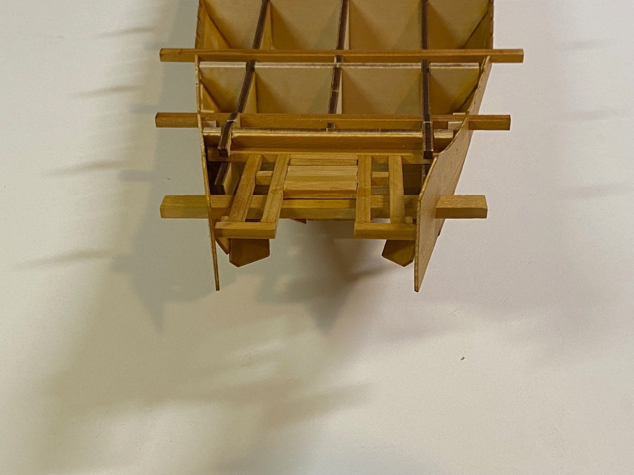
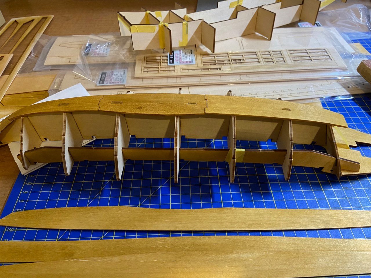
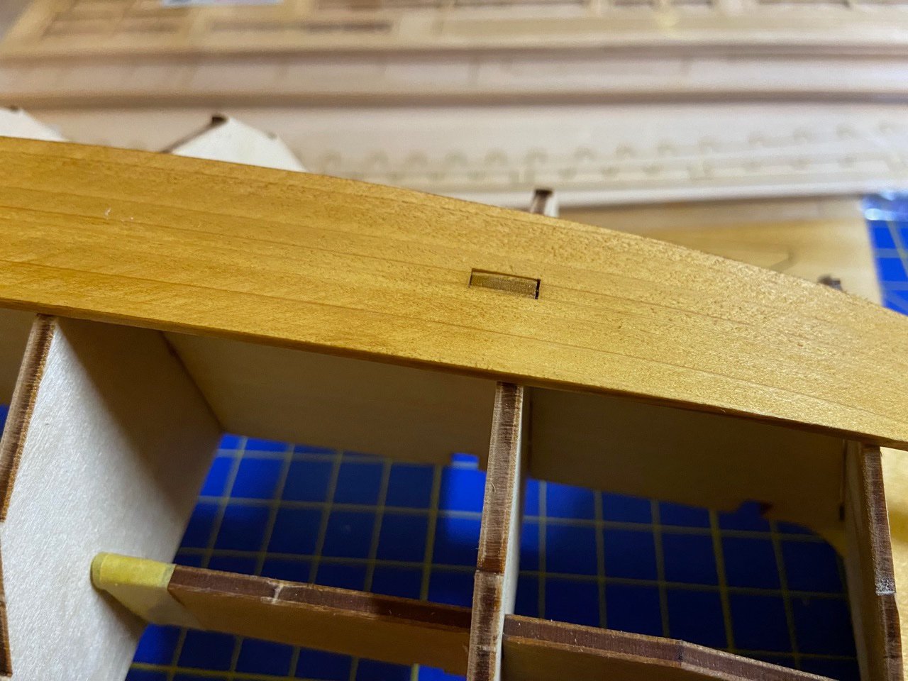
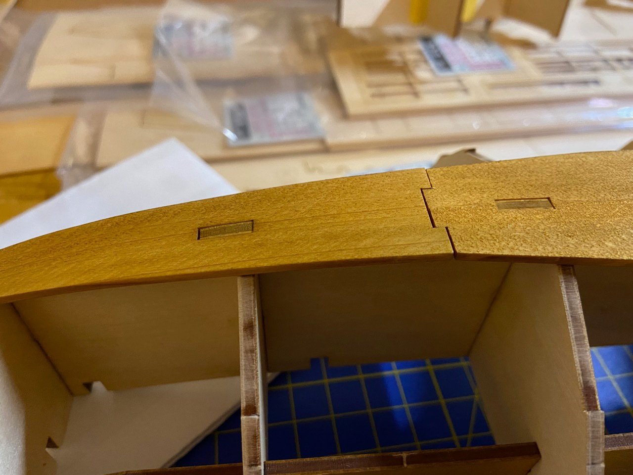
So, I just used a compass to draw a reference line, 1mm down from the top edge of the main body's framework, and cut it down with a carving chisel. The photos below are after that work was done.
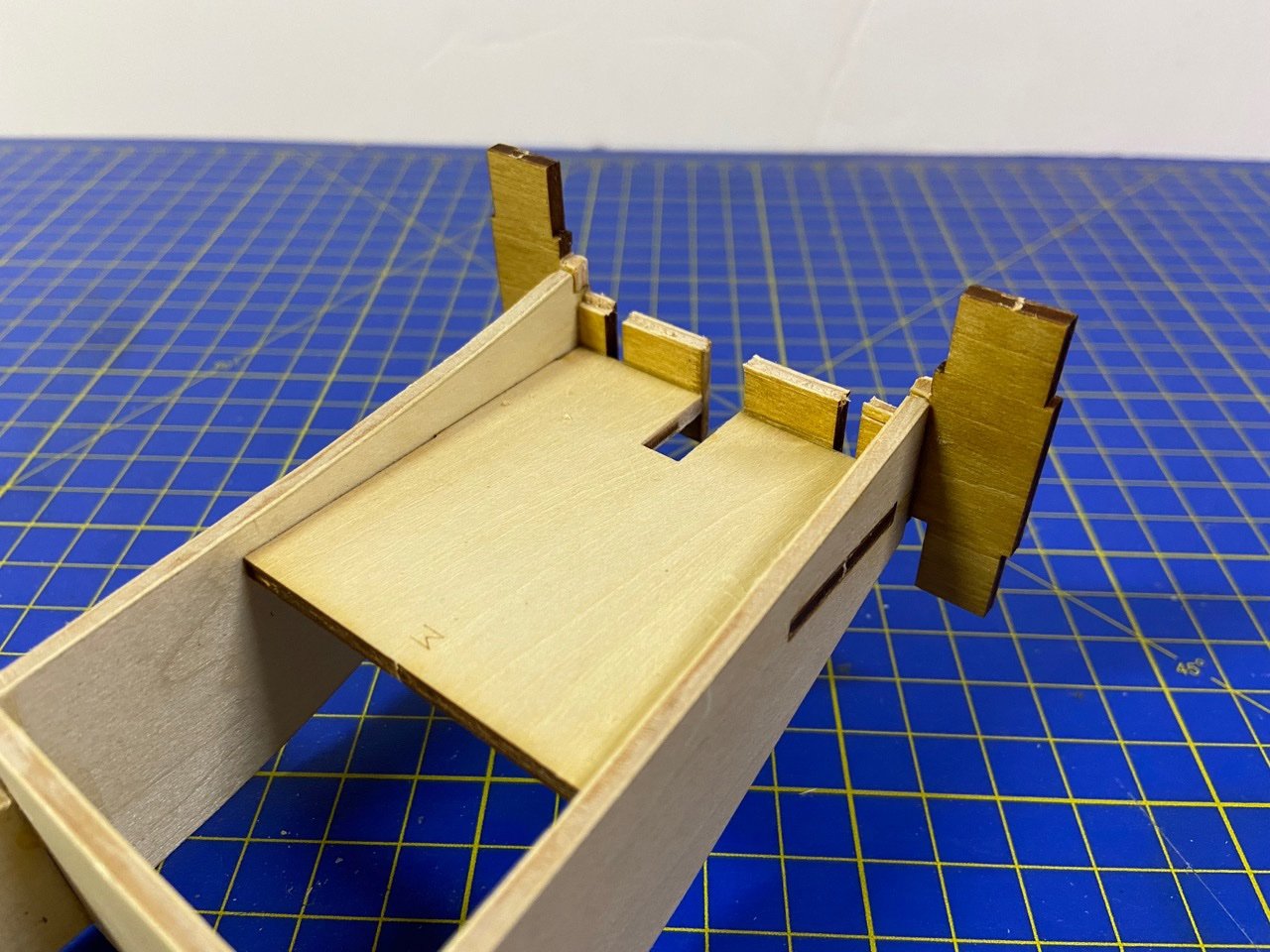
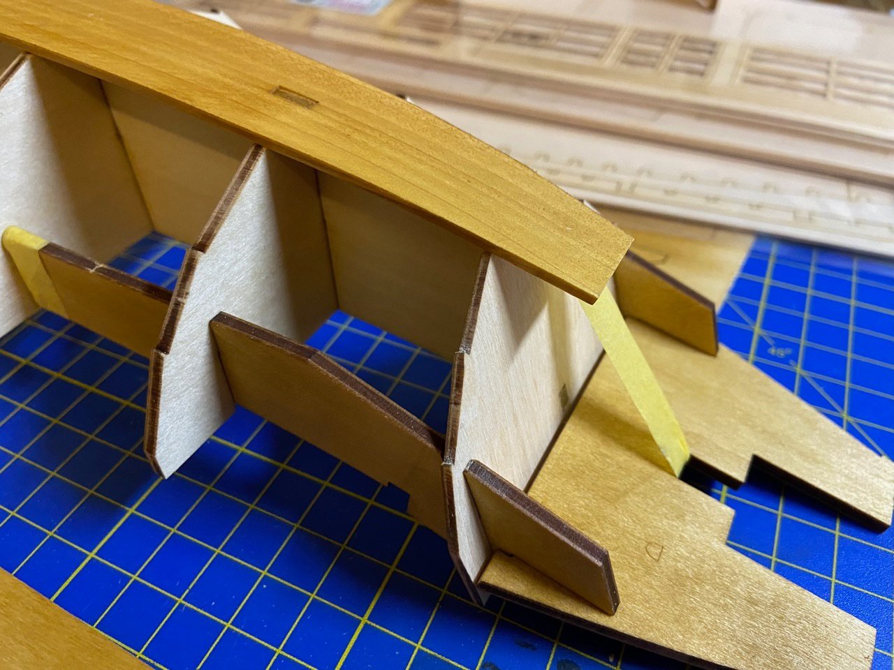
You may also note that I lengthened the slot for the tiller and cut a slot in the back wall of this platform. I also trimmed off the top edge of that back wall to make room for a beam that I'll be adding. I have no special knowledge about a beam there, but makes sense to me. More on this later.
Next, I went ahead and planked this steering deck using some 1mm thick wood strips. The longitudinal deck pieces are really just my guess/imagination, given that the rudder should be raisable, which means that the rudder head may need to drop down to facilitate that. So, I'm imagining that middle plank might need to be removable to allow that.
Now, I have the sides of this little sunken compartment planked, but I think on the real ship, this steering deck may just have been a platform, open on the sides. But, there's no hard evidence, so I'm trying to leave well enough alone there.
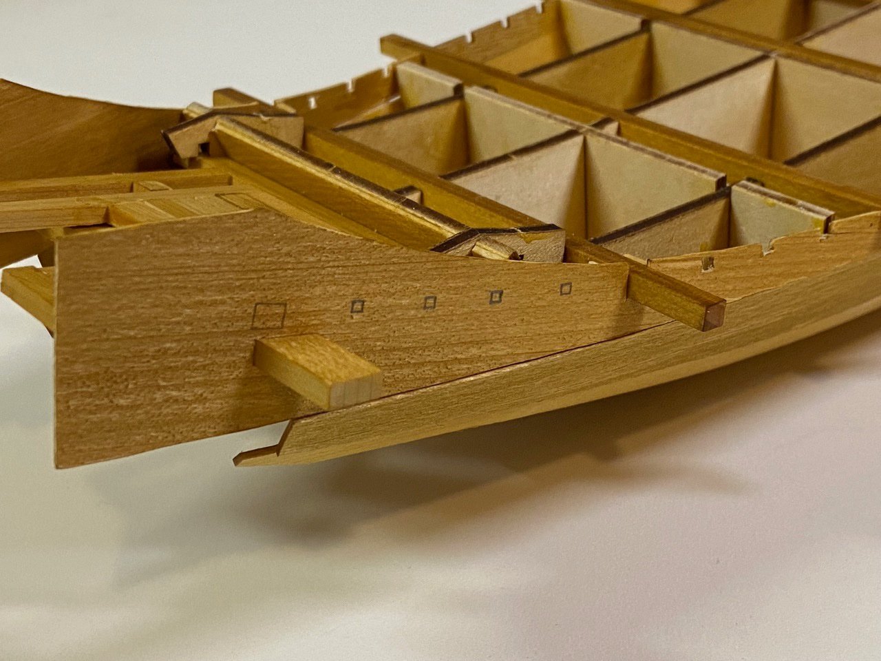
Back to the Lower Hull
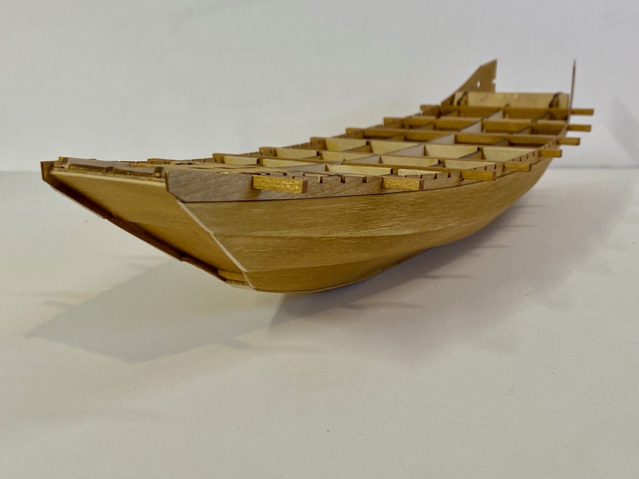
Next step on the construction of the hull was to add the main beams. These are nicely laser-cut, so they're really easy to prep and install on the model. The framework is notched perfectly to take them, the the beams are nicely shaped to lock into position without fuss.
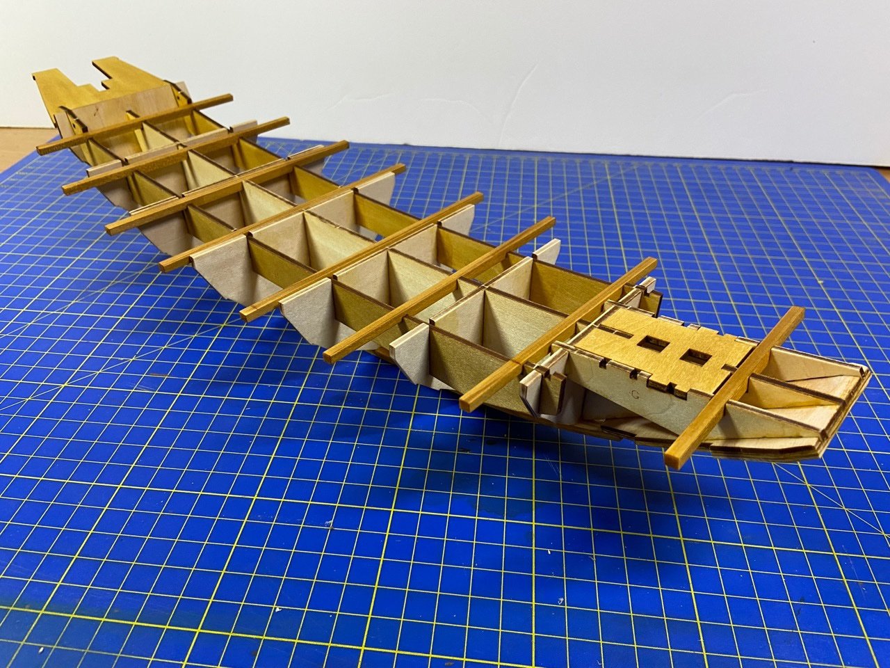
I finally began the process of planking the lower hull, adding the lower most boards. To better match the museum model, I cut the aft ends of the planks so that they extend only a short distance behind the transom. This seemed a pretty simple modification to make.
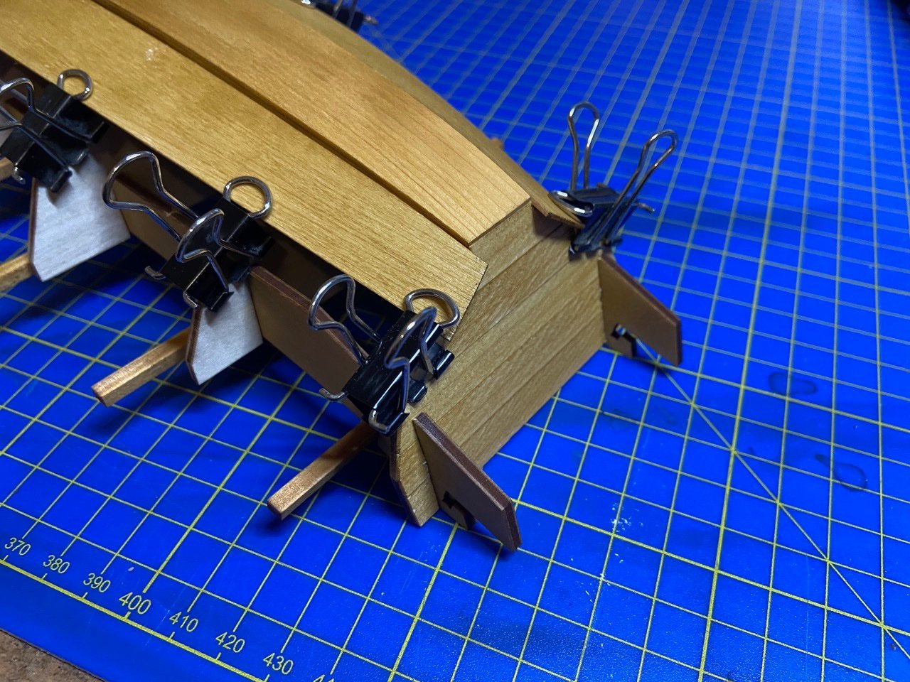
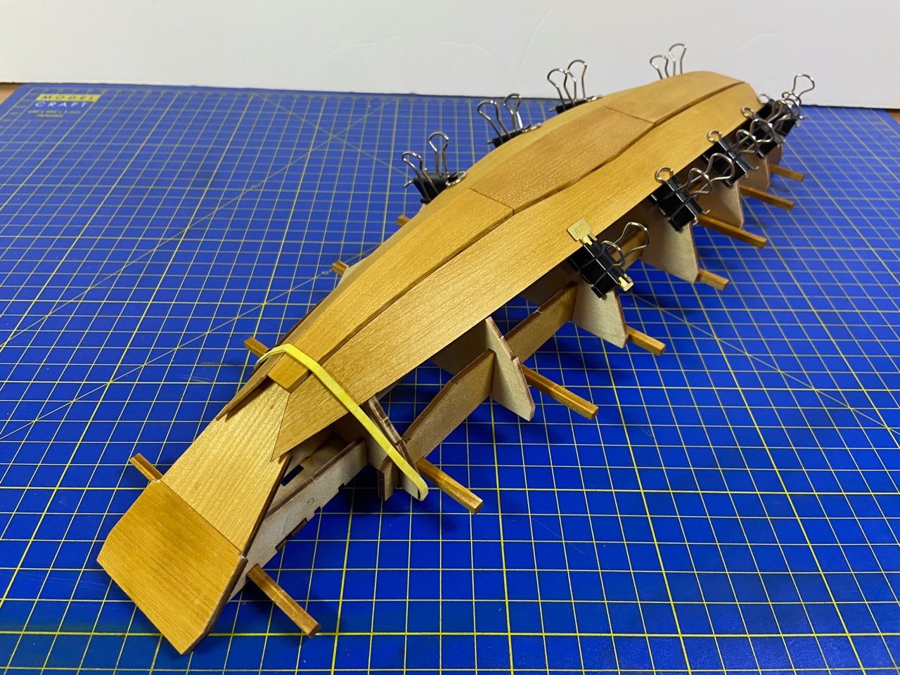
The modified binder clips are ideal for this model. I even made use of the brass pieces produced by Amati for modifying the binder clips, for those who want a fancier solution!
- ccoyle, Ekis, hollowneck and 6 others
-
9
-
I've spent quite a bit of time working out some of the modifications I'm going to be making on this kit. Some things that I might like to do would require some re-engineering and re-fabricating some of the wooden parts, so I don't know if I'll go that far here. Of course, I have a second kit, and I make try those ideas there. But, for this model, most of the modifications are going to be fairly simple.

As discussed before, the first thing I want to do is to get rid of those tabs that show through the wood at the bow and transom boards. I'd already started the process last time by thinning both those parts down. It may not be absolutely necessary to do that. At the transom, some other filing of parts could be filed down a little to accomodate a thicker transom. But, at the bow, it's pretty close the end ends of the hull planks, so making it thicker might make the bow stick out a little too much. Normally, this bow plate is shown as being somewhat recessed. However, I'm thinking I can adjust that slightly with the placement of the hull planks.
For the pieces that make up the hull bottom, I decided to go ahead and sheathe these parts without thinning them down. The bottom of larger vessels is very thick and often extends a bit below the lower planks anyway. So, the appearance would not be unnatural. This was an easy process.

All parts modified to cover visible tabs.
I ended up sheathing the transom piece with multiple strips of 1mm x 10mm wide hinoki. This would be 1 meter wide on the full sized ship, which is big, but certainly historically possible in terms of available lumber.
The bow piece was sheathed in two layers, to appear more closely to may drawings of Atakebune I have seen. This doesn't match the museum model, but I thought the simple added detail might make the model a little more visually interesting.
Happy with the way the parts were looking, I went ahead and glued them to the frame.


One change to note is that the bottom board on the museum model stops flush with the transom piece. This is one of those things that was bugging me a little and I'd been trying to figure out how the hull planks would run and if the structure would be badly affected if I modified the kit to more closely match.
Since it seemed like it would work out, I went ahead and cut the aft-most bottom board piece. However, I also placed the planks on the transom so that the bottom plank stuck out over the edge of the transom by about 1mm. I then made sure to trim the cut edge of the bottom board so that it made a nice fit into the little notch that created.

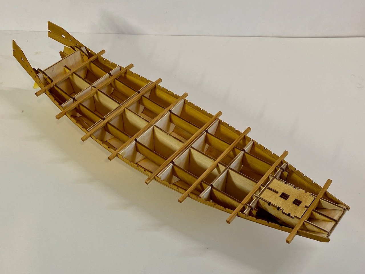
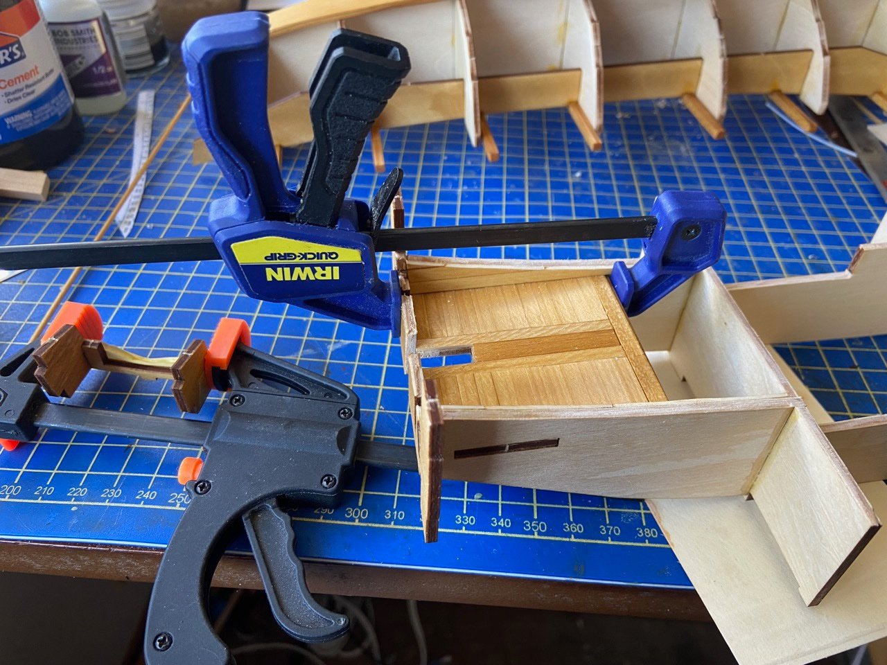
Meanwhile, I decided the box structure was going to work out, pretty much as is, at least at this stage, so I began gluing up those parts.

And maybe I've mentioned this before, but the one modification here is the small sunken steering deck. Given my experience with Japanese coastal transports of the later era, and the way the Japanese traditionally mounted rudders on larger vessels, because the rudder is raisable and needs to rotate slightly when raised, the simple square hole for the rudder post didn't see quite right. So, I ended up elongating the opening and I think I will also cut a slot in the bottom of that back wall.

The kit doesn't call for the planking of this lower deck, but it should be planked, just like with any deck. Because the walls will be visible, I'll also give them some kind of finish. Probably a simple planking as well. This will be an easy modification for my next post.
Meanwhile, check out the posts on the Zootoyz Facebook page showing the excellent progress being made by Mr. Kazunori Morikawa on his Atakebune build, his first wooden ship model kit ever. He's very far along on his build, and has got some very good ideas for some modifications too.
Edit: Note in the last photo, that bulkhead on the end is just pressed into place, it's not a permanent installation, so I didn't pay attention to its orientation for this photo. It's actually on there upside down. So, if you have the kit and are following along, don't copy the piece's orientation from this photo!
- EricWilliamMarshall, mtaylor, Ekis and 7 others
-
10
-
Kazunori Morikawa of Zootoyz has been posting progress on his Atakebune model on the shops Facebook page here. And, if I understand correctly, it's his first wooden ship model kit, and I think he's doing an awesome job building the kit and even modifying it to improve the presentation. I have no doubt he will be finished with it in the next few weeks, so you should check out his work if you don't mind going onto Facebook.
I don't think he will mind me sharing one of his build photos here. I will double-check with him of course. But, this gives you an idea of how this model kit will progress.
Again, this is from Morikawa-san's build, not mine...
If you wait for me to get this far along, you may have a long wait. I'm spending a lot of time seeing how parts fit together, so I know what kind of modifications I can reasonably get away with.
Back to My Model
For my own model, I'm pretty well sticking with the kit on the hull planking, though I may change the bow and transom boards a little as I mentioned earlier. But, before I get too far along, I've decided that I need to test fit things together to get a better understanding of what I might be able to modify without too much difficulty. So, I basically began taping the model together, temporarily fittings pieces into place.

There are essentially three distinct parts of this model: The lower hull, the boxy upper hull structure, and the castle structure. These can actually be built separately and out of order, and I'm considering doing just that. This will buy me some time to figure out what things I want to modify, since the castle-like structure should work pretty well, as is, and setting into place should help me gauge what I can do to the upper hull box structure to make it more unique.
In the meantime, I've dyed all the laser-cut sheets using Transtint wood dye. I've been using this stuff for years now. My mixture is 24 drops of Dark Vintage Maple to 9 drops of Amber, thinned down in a 2oz jar of denatured alcohol. The nice thing about using wood dye versus stain, is that dye does not affect glue joints, so can be applied before gluing parts together.
And, since this build log is supposed to be about my build, here's some photos of what should be the next parts that will actually go onto the model... maybe...
The bottom of the hull, as with all traditional Japanese watercraft, is keel-less. This is the main reason the rudders are so large, as they must act in place of the keel, keeping the ship from sliding sideways too much from wind pressure. Of course, it makes these vessels very easy to beach. the bottom of the model is composed of three interlocking sections with exposed tabs for alignment. Note that I've bent and test fitted these pieces into place, but haven't glued them at this stage.
Below the hull are the pieces for planking the sides. Obviously, the single, long pieces are a simplification. But, more on that later.
The bottom pieces are 2mm thick hinoki, which bends quite easily when damp, but do NOT try to bend the wood without dampening, as it won't bend, but will snap easily.
The exposed tabs are common on the Woody Joe models of Japanese boats. For most of these kits, it's never been an issue, as the bottoms of those boats and ships were commonly painted black. However, I've never seen an Atakebune represented with a painted bottom. If anything, the Japanese might have used fire to scorch the wood on the bottom to harden it and make it resistant to rot and insects.
But, the tabs are on the underside of the model, and will be very hard to see unless one picks up the model – not an easy task once all the sculling oars are added. So the tabs may be a non-issue. However, like with the bow plate and the transom plates, one easy possibility might be to sheath the bottom piece with 1mm wood. In fact, that could probably be done without thinning the existing pieces, as the bottom of these ships were thick, and may very well have protruded slightly below the bottom hull planks.
Sheathing would hide the tabs as well as those interlocking seams.
Before I started this post, I was thinking I wasn't going to worry about it. But now, I'm thinking I may just do it. What the heck? I'm considering so many modifications now that the project will probably drag on for a lot longer than it should. As if I've never done that before!
-
Well, last night, I decided to update my blog, and I ended up writing and writing, and writing... and writing. I ended up spending hours, well into the wee hours of the morning writing. Much of what I wrote, I decided to store away for future discussions and blog entries, or maybe an article somewhere.
For this build log, I'm starting with just the beginning of what I wrote, so there's room for others to chime in.
I hope others do chime in, as I'm not an expert in the area of Japanese boats and especially not an expert on these Sengoku Period warships. And, as a student of the subject, I'm learning as I go, and trying to retain what I've learned elsewhere (with my brain, that's getting increasingly difficult to do!).
Ekis brought up an interesting topic that I had to really think about, the true nature of these large, flat-sided hull planks presented by the Woody Joe kit and the Nagoya Castle Museum model. More about this later, but it's what I spent most of my time pondering and researching/reviewing. But for now, the model...
Moving Along
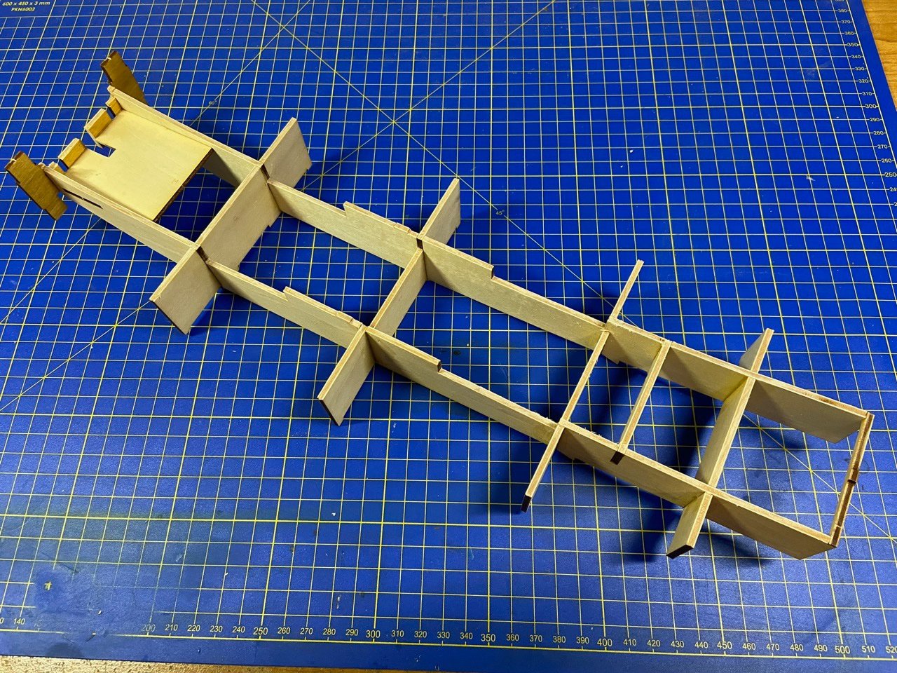
I'm taking it easy on getting this new model kit started. Last time I posted, I really only had cut out the initial parts I needed and then dry-fit them together. This week, I glued together the basic hull frames, using machinists squares to check and set alignment. I used Titebond wood glue for this work.

I spent a lot of time trying to decide what I wanted to do with the bow and transom pieces. These pieces have holes in them that alignment tabs in the keel piece will lock into. The thing I don't like about this, is that they are then visible on the finished model. As far as I can tell, there are 5 tabs total that will be visible on the completed model, as designed.
Since I'm dying the wood, these tabs shouldn't be as noticeable as on a kit built straight from the box. Still, I've considered solutions, and one is to thickness sand the bow and transom pieces down by 1mm, then use 1mm sheet wood to cover them. The covering wood will have no holes in it, so no tabs will be visible. In order that everything still fits together, I will have to file the tabs down by 1mm.

You can see from the photo below how the tabs stick out now.

About the Bow
Now, there is one other thing about the bow that I'm considering changing. The Woody Joe kit is based on the museum model in the Saga Prefectural Nagoya Castle Museum, but I'm sure that model has some simplifications, as I believe I've mentioned earlier. One of those possible simplifications is the design of the bow.
Many paintings and museum models usually show the bow of the Atakebune to be made up sections, often overlapping ones. I've been playing around with the idea of introducing that feature to this model. Of course, paintings and museum models are not real evidence, since the paintings and models are pretty modern reconstructions.

The two main types of bow of the Atakebune. On the left is the type of bow shown by the Woody Joe model. Note it appears here as two large pieces that are mounted flush.
Based on this illustration from the book Wasen II by Professor Kenji Ishii, it would be simple to represent the bow as shown on the left. Since I'm already planning to sheathe the face of the bow plate, it would be relatively simple to use two pieces of wood to recreate this appearance. I've seen more complicated arrangements, but I don't know if complexity is necessary or particularly accurate in this case.
-
Hi Ekis. I just looked up Japanese red cedar, which is very common in Japan and probably what was used to construct Atakebune. It's the type of wood that seems to have been used predominantly in wooden boat building in Japan.
It turns out that the trees can have trunks up to 4 meters wide, and I know that certain Edo period riverboats had hulls that were supposedly made from individual planks that were close to 2 meters wide. I didn't know if I really believed this, but now I think it makes sense.
You will, of course, need to make your own decisions on things, but I think 2 meter wide boards would not be at all far fetched.
As for Korean turtle boats, I wouldn't think there would be much connection there. Different shape, different construction style, different traditions.
Also, one last point to consider is that the Japanese typically use calking between planks on their smaller boats, only at the chines, if they used it at all. This makes seams between adjacent planks pretty hard to see. At 1/100 scale, it would be invisible.
In fact, when I think about it, I only use separate planks on models at 1/10 scale. Even at that scale, you can only tell that the planks are separate parts because the grain and figuring of the wood is slightly different between the two. Without that, you'd never know.
This is a really good and important topic, and I think I'm going to continue it on my Atakebune build log here.
- Jack12477, FriedClams, druxey and 1 other
-
4
-
Hi Bob,
I used Transtint brand dye I buy from Rockler. I just add a few drops to a small mixing jar, add denatured alcohol. Then, I just use a piece of cloth to wipe it onto the wood. You'll want to experiment with mixtures of color and your wiping technique to get consistent color. Since it's a dye, I apply it to all the parts before assembly, as it won't affect the glue joints. Sometimes, I take a thinned mixture and brush it on afterwards, but only if I was really careful with the glue not getting onto the finished surface of the wood.
I usually try to mix up a batch that will last me through a project, to make sure to avoid color variation.
-
16 hours ago, Roger Pellett said:
What wood are your models made from? It certainly results in a crisp, clean appearance.
Hi Roger, thanks for the comments.
Most of my models are made from a wood that the Japanese call Hinoki, it's Japanese cypress. It's a lightweight wood, kind of like basswood, but doesn't fuzz up when sanded. Over time, the color will turn to a nice tan color, but starts off very light, which is why I dye the wood. It is actually quite brittle when dry, but it doesn't take much to dampen the wood enough to make it bend. Closest wood in the States is Port Orford cedar, which I have used with some models.
For the 1/10 scale models, I use a wood called Sugi, which is Japanese cedar. It's the same wood that most boatbuilders use on their actual boats. It's not a great wood to work with, but I use it to maintain the Japanese model aesthetic (props to Ekis!).
- BobG, FriedClams, mtaylor and 1 other
-
4
-
Hello Ekis,
You bring up an interesting topic about aesthetics and accuracy between east and west. I'll have to think about it a bit.
But, one really big issue is that there is almost no historical information on the construction of these ships. Something as obvious as the construction of those hull "sheets" is not just simplified because it makes the kit easier. It's also done because nobody really knows how they made the large flat sides. Certainly, they weren't one solid sheet as you say. But, there's also a tendency for us to think that it was made up of strakes. Clearly, they would have to use smaller boards, but they would actually be quite wide, and may not run the way we might think they do.
Details like this is one of the main reasons Woody Joe rejected the idea of producing an Atakebune kit in the first place.
The Higaki Kaisen is another matter, as these ships were around into the 20th century, and there was the recently built reproduction to pattern the kit after. But, even that has simplifications compared to the actual hull planks, which have been documented. Still, it shows
I kind of run into this issue a lot on my models of Japanese watercraft. In my mind, it's better to simplify than to add details showing the world how much I don't know... 🙂
Perhaps that's part of the cultural aesthetic?
In any case, I'm interested to learn what you come up with. I actually had considered a hull planking modification for a while, based on drawings, paintings, and models of other Atakebune.
- mtaylor, FriedClams, druxey and 2 others
-
5
-
Peter, Bob, Mike, thanks for the kind words of support!
Ekis, the Higaki Kaisen kit is a more serious ship model kit. Woody Joe really designs their kits to be buildable by first time modelers. But, their Higaki Kaisen kit is more of a ship model kit for ship modelers, designed with the assistance of the former president of the ship model club the Rope Tokyo. Definitely more challenging a kit than the Kitamaebune kit, and supposedly even the Atakebune kit. I wrote a 3-part article in Seaways' Ships in Scale on it, so I'm interested to know what you think about the kit.
-
Thanks Druxey, Mark.
Ron, I've been using Transtint dye thinned with denatured alcohol for all my Japanese boat models. The mix I'm going to try here is 24 drops of Dark Vintage Maple, 9 drops of Amber, to 2oz of denatured alcohol. That's a bit darker than I've done for most of my Japanese boat models. But, any coloring will reduce the appearance of the plywood, laser char, and seams. I'm not sure if I'll use the same mixture for the decks. I may go with less of the Dark Vintage Maple, or just apply the same mixture, but thinned with more alcohol.
All the thicker laser-cut wood seems to be maple ply. It's mostly internal structure, but the main box-shaped body of the ship is this ply and so is the bow and transom pieces. Turns out that this stuff takes the dye really nicely. But, I think I'm going to end up covering up the bow and transom pieces with a thin layer of Japanese cypress. While it will then match the wood used for the hull, that's not why I'm doing it.
There are a couple places where Woody Joe put some locking tabs that poke through the wood in those pieces. I've decided, at minimum, to thickness sand those pieces down from 3mm to 2mm, and to cover them with a solid layer of 1mm Japanese cypress. This will cover those tabs.
But, even if I didn't do this, the stain will make the tabs less noticeable. And, there is really only one in the bow that will be visible, and maybe two in the transom. But, the transom is generally hidden except when viewed from behind the ship.
I'll post details about this shortly.
-
Hello All, I'm a little burned out on posting build logs these days, but this kits is a brand new release and kind of important to me. I know there are others here that want to read more about the kit and some of the modification that could be done to make it stand out better, so I figured I'll get my build log started. However, to save time, since I maintain my own blog site, I'm pretty much just copying the contents from there to here, though there's room for questions and discussion here, so please chime in.
Let me begin by saying that while I've been doing a lot of work studying and building Japanese wooden boats, I don't have a great deal of historical knowledge about the warships of Japan's Warring States period, except that the at this time, the Japanese basically had three classes of warships. The smallest were called Kobaya, which were literally small fast boats. The mainstay were the Sekibune, sometimes called Hayabune. They were like the cruisers of day and were large and relatively maneuverable and provided good protection for their occupants, then there were the heavies, which were called Atakebune. They were somewhat large and lumbering and formed the core of a naval formation.
The Atakebune is the subject of a new kit from the Japanese wooden kit manufacturer Woody Joe. It's something that I, Kazunori Morikawa of Zootoyz, and a few others were actively petitioning Woody Joe to produce. There was hesitancy on their part as there is actually very little solid information on the construction of these largest of Sengoku Period Japanese warships.

I don't know what changed their minds and got them to produce this kit, but my feeling was that if they could produce a kit based on a museum model, then it would essentially be a model of a model, which is not without precedent, and is a perfectly valid subject, in my opinion.
The first news I heard that Woody Joe was actively developing this kit was in early Summer, and that they were basing it on the large model in the Saga Prefectural Nagoya Castle Museum. I was initially hoping that they would produce the kit at a scale of 1:72, as that is then scale comparable to their Higaki Kaisen and Kitamaebune kits. It would also then be compatible with available 1/72-scale samurai figures. But, the demands of the manufacturing process, costs, shipping boxes, and all meant it would be 1/100 scale.

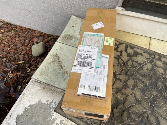
In any case, we finally got word that the kit was to be released at the beginning of November. As I had four months to prepare to place my order, I had saved up and asked Mr. Morikawa at Zootoyz to set aside two kits for me. And, as soon as shipments went out from Woody Joe, I placed my order. Amazingly, less than a week after they were shipped from Japan, they were at my door.
The costs of wooden kits from Japan are pretty pricey, and at ¥38,000, this kit is no exception. However, I had actually expected this kit to be a little more expensive. As it is, with the current exchange rate in our favor here in the U.S., the price comes out to about $336. Now, shipping is a particularly difficult issue, as it was expensive before Covid. Then, for about a year, Japan Post would ship at all to the U.S. That changed in the Summer, but prices for shipping were higher than before.
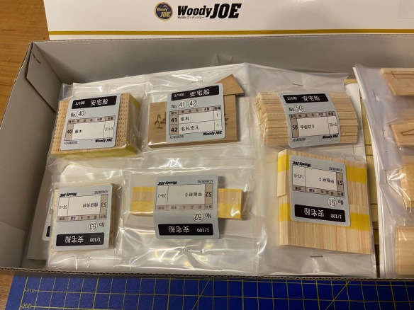
About the Kit
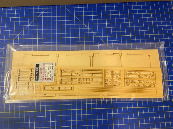
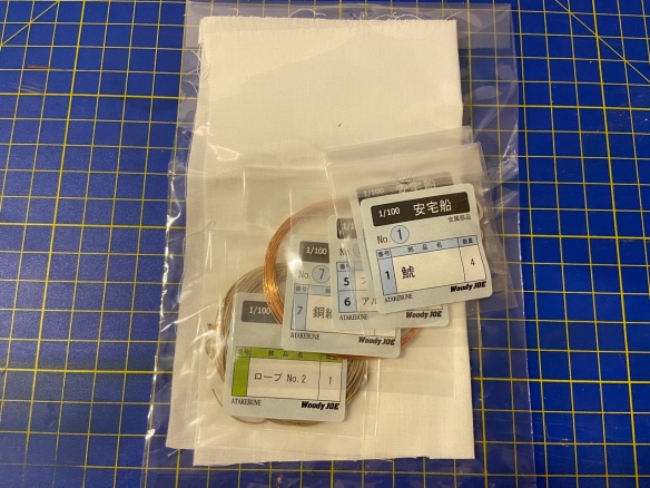
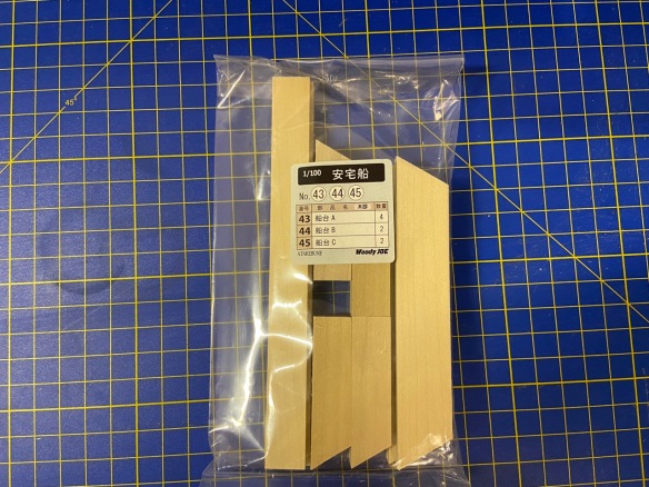
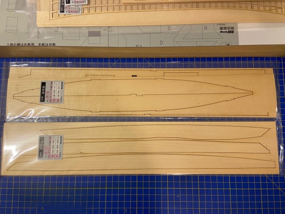
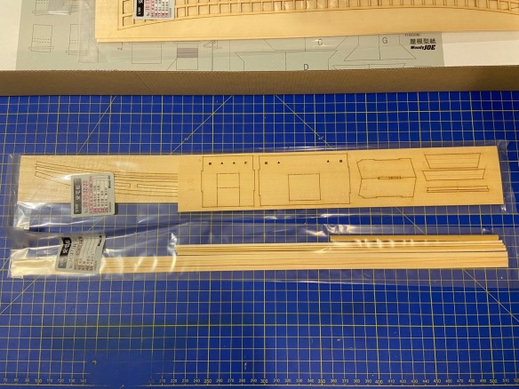
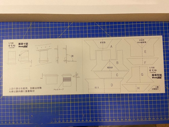
I'm not going to get into a lot of detailed description of the kit contents. Woody Joe kits are pretty consistent in terms of what you get, what the instructions are like, how parts are identified, and all. So, I'll just post some photos of the kit contents as I removed them from the box.
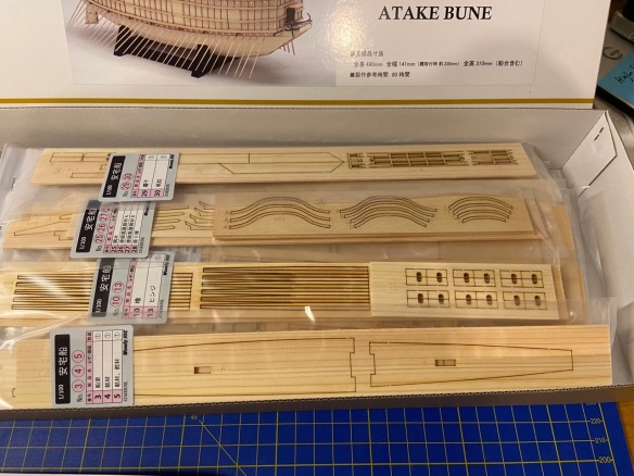


According to the Woody Joe product information, this kit will take approximately 80 hours to complete. Of course, that figure goes out the window if you are going to add any extra details to it to improve on the basic kit. But, this gives a good comparison, whereas their Hacchoro kit is listed at 50 hours, their Kitamaebune kit at 70 hours, and their Higaki Kaisen kit at 100 hours.
In terms of difficulty, the Atakebune is rated by Woody Joe as a skill level 3 kit on their scale of 1 to 5, with 5 being the most difficult. In comparison, both the Hacchoro and Kitamaebune are listed as skill level 2, with the Higaki Kaisen listed as a skill level 4.
My Atakebune Build
Build logs can get very repetitive after you've read or written a few. So, I think I'll keep this pretty simple and just post some photos as I go. I'll discuss issues and modifications along the way.
But, I'll begin by saying that this seems like a very straightforward kit. It's a little bit light on some small details, but all the major details appear to be here. I think the challenge of this kit is that it's like a ship kit PLUS a small castle kit, so you get the challenges of both.
As for accuracy, it appears very close to the museum model it's based on, though there are a few minor difference that can be spotted right away. One is the doors in the side of the hull structure. On the museum model, these are basically double doors that swing outward. The Woody Joe kit makes these drop down doors that act like a boarding ramp. I don't know which is correct, but I have seen drop down doors on other Atakebune museum models. Perhaps this is Woody Joe's work to make the model more accurate, or maybe it just to make it more interesting, as these seem to be designed with hinges, so you can open them up as you like.
My first planned modification of the model is to dye all the exposed wood, so I made up my mixture of wood dye, going a little darker than I have in other models, and prepped a pair of jars, which should last through this model. But, I've recorded my formula, so I can always mix some more if needed.
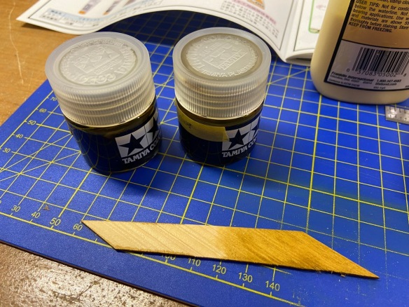
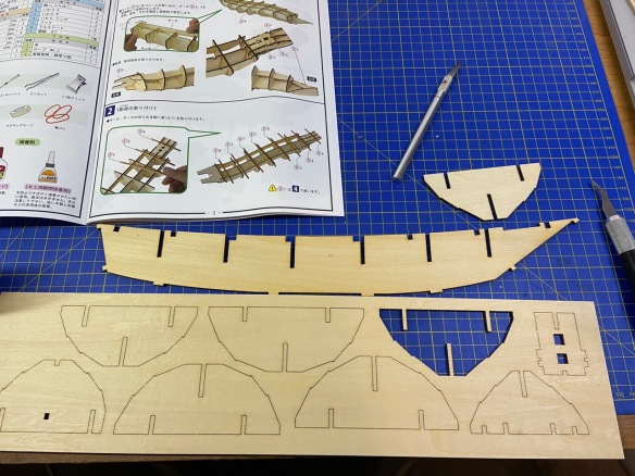
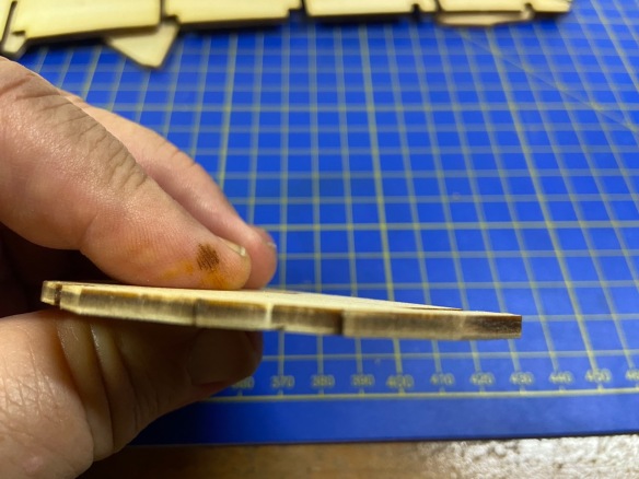
With laser cut parts, you always end up with char on the edges. As ship modelers, we've trained ourselves that char must be removed to make for better glue joints. But, with laser-cut kits, you have to be very careful about this, as the kits are engineered to fit together as designed. It's a good idea to file off some of the char, but you don't want to remove much wood, as that will change the way parts will fit. So, below, you can see how much char is on the edge of a part that hasn't been cleaned up, and then the edge of one after I've rubbed it down with a few light strokes of a sanding block.

Below, you can see the first parts I've cut out for the hull skeleton. But, at this stage, I'm just test fitting. Next time, I'll have some parts glued up.
In the meantime, Mr. Morikawa of Zootoyz is building the Atakebune as his first wooden model kit, and you can follow his work as he posts his progress on the Zootoyz Facebook page here.
As I begin the first steps of this kit, I am thinking about how to make this kit more like the museum model. But, at the same time, I am wondering how accurate the museum model is. Many Japanese museum models that I've seen in person and on the Internet are built to represent a particular ship or type of ship or boat, but are not necessarily built with detail and scale accuracy.
For instance, the hull planks on this and the museum model are made from a single sheet of wood. Certainly, on a ship of this size, that's not possible. I've seen some Atakebune museum models and illustrations that show large areas where planks are overlapped. And, certainly, planks as wide as those used for this ship are made up of narrower planks that were edge fastened. But, at this scale, those individual planks would not be noticeable, though large overlapped joints would be quite visible. But, since they are not on the museum model, we'll assume that this is correct.
However, one feature that appears on the museum model that could easily be added here are the beams whose ends just pierce the hull. You can see these along the length of the museum model.
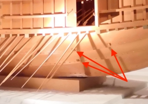
In addition, you can see the nail mortises along the edge of each plank. These are normally covered with copper plates, as are the ends of the beams, including those that support the sculling oars above. I've simulated these as an oxidized brown color on my Kitamaebune model, and I could do that here as well.
One more thing that I spotted is that if you look closely at the following photo of the museum model, you can see a kind of gallows structure at the head of the rudder. This would be a pair of heavy posts supporting a windlass. I don't know what the windlass is for exactly, but a similar structure exists on the Higaki Kaisen and Kitamaebune, and the whole thing generally supports a rope that wraps around the rudder head to keep it in position.

This structure should be easy enough to add. In addition, I noticed that the whole rudder platform that is slightly recessed down below the top deck has no planking. It's just a solid piece of plywood. So, I plan on fixing that too.
I'm sure there are some other places where I think the model can be improved, but these few should go a long way toward a nicer looking model.
-
By the way, Ekis, is there any word on the repair of the Bleriot model? Did someone ever connect with your friend to do a repair?


Hello From California
in New member Introductions
Posted
Hi Dan,
Don't listen to Chris – he's not even in the state anymore! 😀 By the way, you're just down the road from me, almost literally. I'm probably less than 10 miles from you, up in Pleasant Hill.
Welcome to MSW!