HOLIDAY DONATION DRIVE - SUPPORT MSW - DO YOUR PART TO KEEP THIS GREAT FORUM GOING! (89 donations so far out of 49,000 members - C'mon guys!)
×


robdurant
-
Posts
842 -
Joined
-
Last visited
Content Type
Profiles
Forums
Gallery
Events
Everything posted by robdurant
-
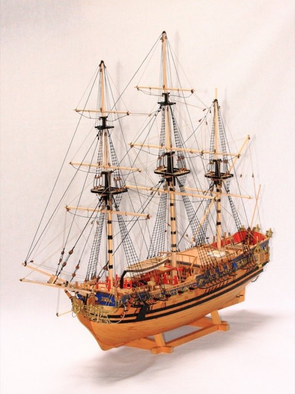
 Mind if I add my tuppence on taking photos? If you're outside, I'd try shade (with the background in shade) or a cloudy day. Direct sunlight tends to cause burn out (where the whites and blacks have no detail vecause the sensor in the camera can't cope with the extreme range)... clouds act as a natural diffuser. If you can get a background that's a long way behind the model you may be able to get it blurred (setting the aperture to be wide - a small f number accomplishes this too) and that helps to make the detail stick out more. That said, your pictures to this point show a very handsome model!
- 843 replies
-
- 4
-

-
- niagara
- model shipways
- (and 2 more)
-
Thanks so much for the encouraging comments. I'm really pleased with the colour of the boxwood - it's really lovely stuff! I've been wondering about the finish - I've noticed that Minwax wipe on poly seems to be a favourite with many, but it's hard to get hold of in the UK. Any suggestions of what I might use in its place? And have others used a Satin or Matt finish?... I've noticed there are water-based and solvent based versions, and I think someone had said the solvent version might give a more rich colour? (I guess a test is called for, but I can't run to buying every varnish in the shop just to try them out ) In the past, I've tended to go with a Matt finish, but it'd be nice to really show this wood off. Finally, should I only varnish the areas that won't have paint on them, or the whole...? Lots of new questions tell me I'm heading for a new stage of the build! Take care Rob
-
A small update... I've finished planking the starboard side (all except for a tiny stealer, anyway). The walnut below the waterline will be covered up with copper tiles.

- 275 replies
-
- 11
-
-
Fantastic! This was the first wooden model I built. Such a lovely model to work on... well designed, brilliant instructions (streets apart from Caldercraft's earlier models) and plans, and makes up into a really handsome model (although I'm sure yours will be streets ahead of my humble efforts). Hope you don't mind if I pull up a chair too. I notice that your first bulkhead from the bow doesn't suffer from the uneven top that mine had.
-
Wow. I love this bit of the build where the deck - and so the ship - starts to spring to life. It begins to feel like a place you could walk round. Great work.... and an inspiration for when I reach this stage. Love the bitts and manger!
-
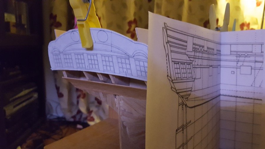
A brief update... I've begun the second planking with 0.7mm boxwood veneer. I've also taken a little time to look at the stern to make sure everything's lined up. This required taking the stern elevation (from AOTS) and stretching it (the plans are square to the stern, whereas the stern itself is angled so the top is further astern than the bottom. The difference seems small, but the picture below demonstrates how much difference it actually makes. I'm planning to attempt Dirk's method of using veneer to make the stern lights (windows) when the time comes, as the Photo-etch stern lights will not fit. The Admiralty (Caldercraft) ebony stain arrived, and the wales were given a couple (four?) of coats to bring the walnut base into line with the blackened boxwood. I wanted to do this before I began the planking to get a perfect line on the wale. Then it was time to put some planks on. Four planks above the black strake, and one below the wale so far. It's worth noting if you reach this stage that there are two types of surround for the gun ports. The sternmost three ports and foremost one have lids, and so the second planking stops 1mm short of the port. The remaining ports are planked flush with the edge of the gunport, as they will have no lid. At least, that's my interpretation. I'm looking forward to seeing how the hull looks as all the messy red around the gunports disappears. It's been looking like someone attacked it with lipstick up until now. Overall I'm impressed with how neat the veneer looks. It's thin enough to be easy to shape and get to stick on to the hull, but not too thin that it disintegrates. It's excellent quality wood (prepared and sold as stringers for instruments and marquetry), and definitely a whole lot cheaper than buying boxwood from the United States, given I'm in the UK. In fact, it's sold by a company about 30 minutes down the road from me that I discovered through google (http://www.originalmarquetry.co.uk/), so really easy to get hold of. I love the rich honey colour of the box. It will really stand out, and look good against the blues, blacks and reds on the hull as I get further along. Happy building Rob

-
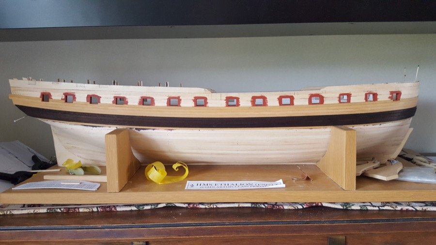
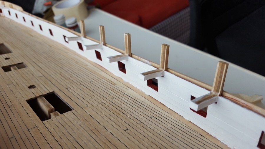
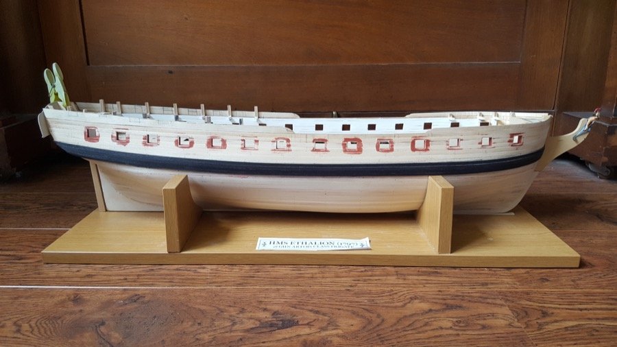
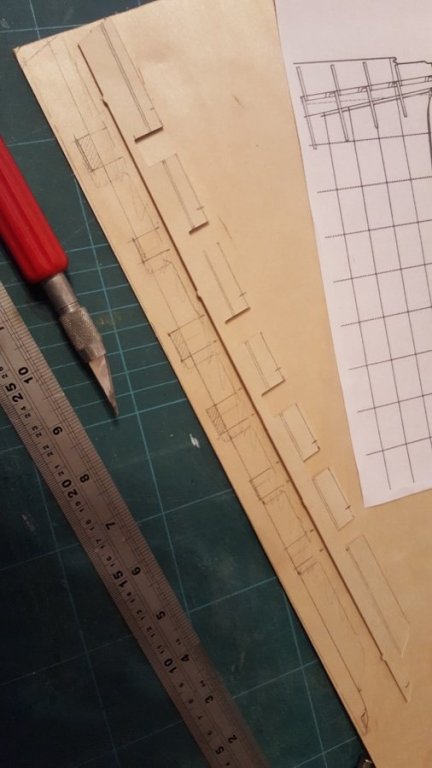
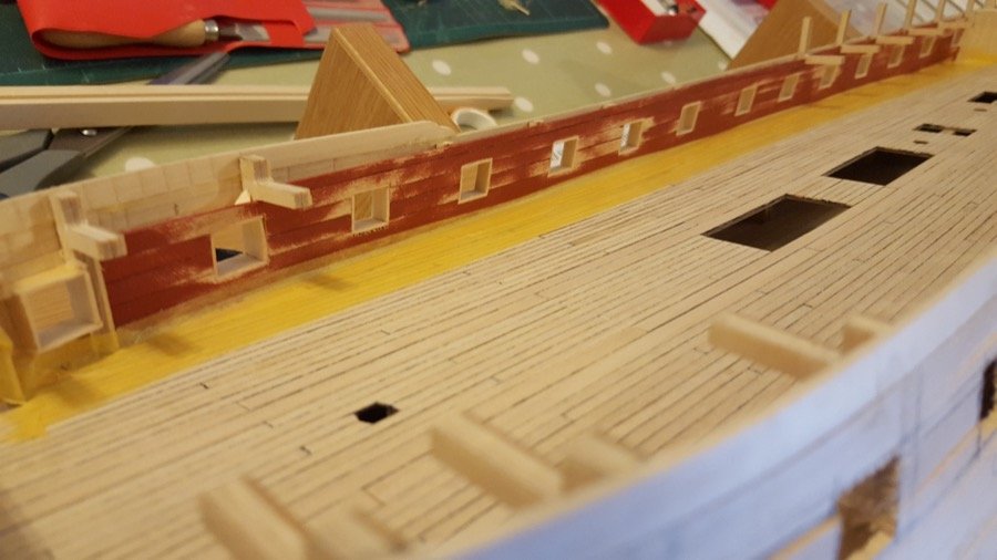
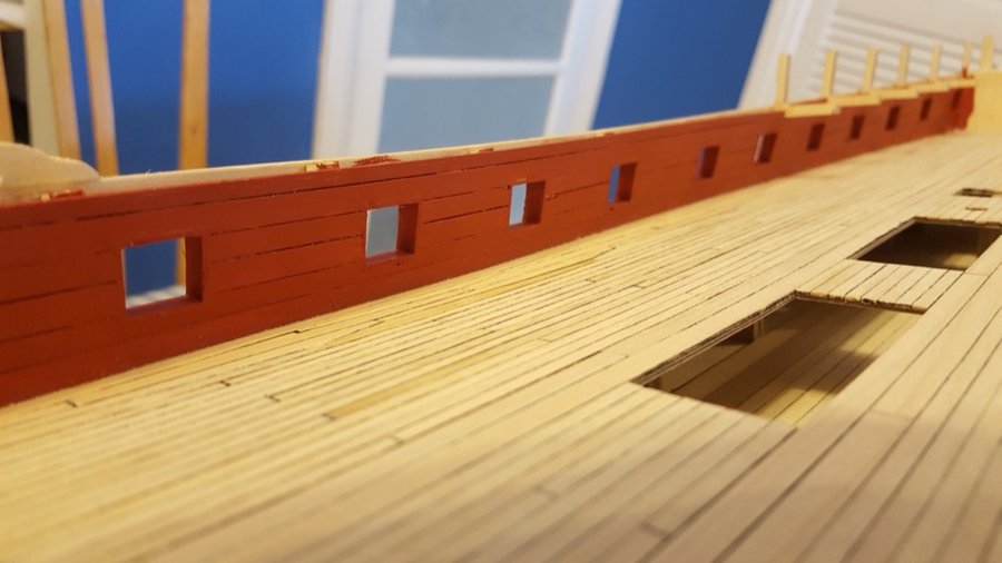
Time for an update. As always, thank you for the likes and encouragement. I'm not quite sure where I'll go with the decorations, but thankfully I still have a while to ponder that. Perhaps some fishes... I will take that advice and check out the alignment of the lower cheek. I'm somewhat dreading trying to get everything to line up, but as you say, fore-planning will hopefully take some of the pain out of the process. In the meantime, I had the wonderful opportunity to visit Portsmouth historic dockyard. It was wonderful to be able to go round Victory again, and I was quite taken with the white bulwarks on the gundeck. Not sure if they're a little anachronistic on Ethalion, but I thought I'd have them white instead of red or ochre. We'll just assume that the captain fancied having them that way. I'm hoping it will allow a little more light to see everything once the quarter deck, foredeck and gangways are on. It also created a nice contrast with the walnut waterway(?) I added between the deck and the bulwark. The walnut wasn't in place when I took the photo below. The gunports are all lined now and remain the red ochre. The second task attempted was to build up the templates for the quarter deck bulwarks. Having decided that I wanted to have the railings on the quarterdeck (as per the NMM plans, rather than the AOTS plans), I thought I needed to modify the ply templates by cutting them down. However, when I checked the templates they were way off. In the photo below, the template sat on top of the ply is the kit provided template. The outline of this template can be seen faintly drawn on the ply below, along with the ports that are defined on the NMM and AOTS plans, which are all approx 5mm further towards the stern of the boat. The heights of the carronade and cannon ports are also different. When built, Ethalion (as per AOTS) had a quarterdeck armament six 32lb Carronade and six 9lb cannon in the following arrangement. STERN – Carronade – Cannon – Carronade – Carronade – Cannon – Cannon – WAIST This is reflected in the size of the ports. I decided not to cut out the ports until the bulwarks were planked, in order to keep them strong, and allow any minor adjustments to be made. Main Wale I wanted to plank in line with the wale, so the wale needed to go on first. That gave me another challenge. To get the wale in the right place, I needed the waterline, and that wasn't marked yet. So. It was a job of propping up the hull (with 6mm clearance off the floor at the bow, and none at the stern), with masking tape to stick it in place, then using a jury rigged contraption to mark out the waterline. Once the waterline was marked, the wale could be carefully measured and marked out. These measurements were taken from the AOTS plans. Once I was satisfied with the sweep of the wale, I put the first of the 3mm strips in place. I built up a layer of 3mm strips, then the black strake was created with 4mm black-stained boxwood strip. Then the wale below was built up with more 3mm walnut and covered with black-stained boxwood. Once sanded and scraped to smooth it, the whole was stained with admiralty ebony stain to bring the walnut into line with the boxwood.

-
Hi Ben, What a great start! As far as the ship's boat goes, it looks very similar to the launch on HM Schooner Pickle (also by Caldercraft) - and that was one of the most recent kits, so it has the downloadable manual here: http://www.jotika-ltd.com/Pages/1024768/Manuals_Pickle.htm . Take a look at pages 53-56 for details and photos of how it all goes together. All the best Rob
-
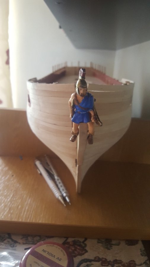
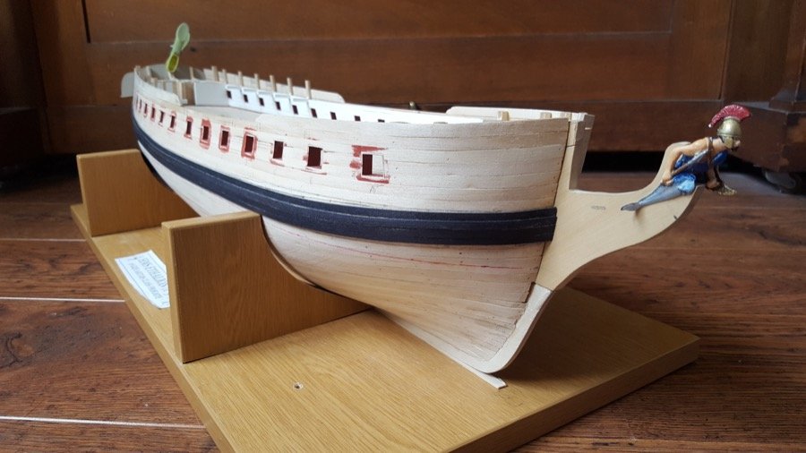
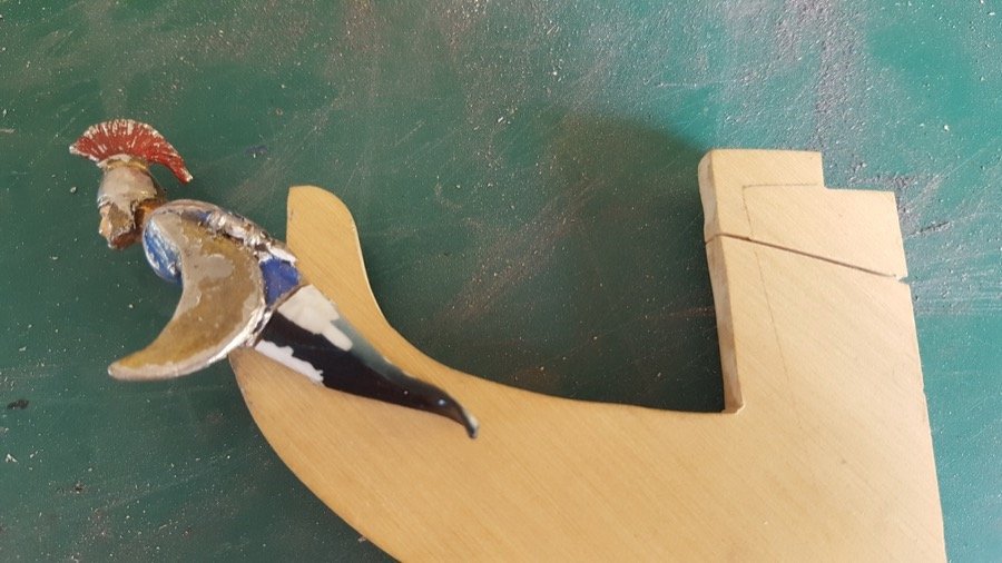
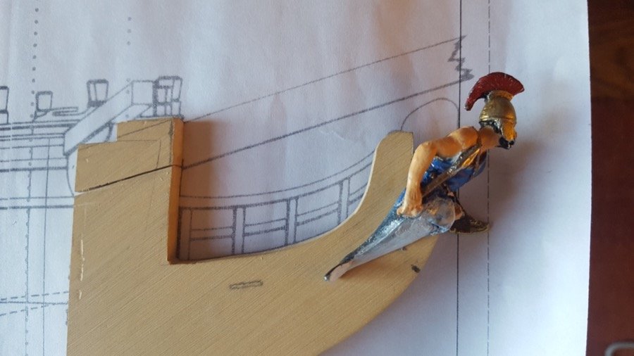
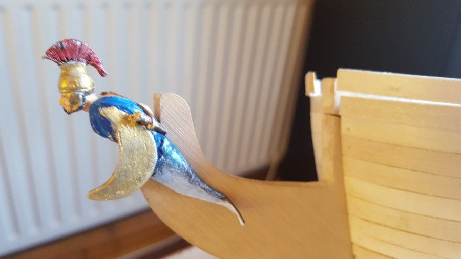
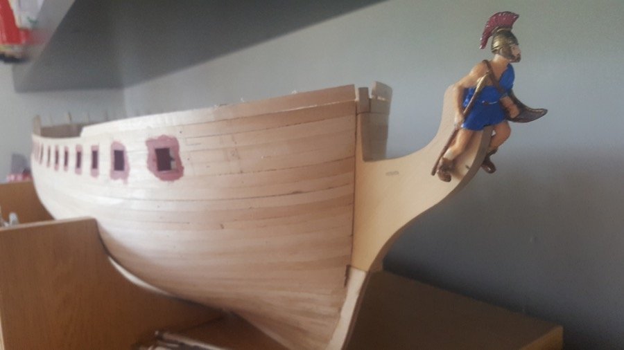
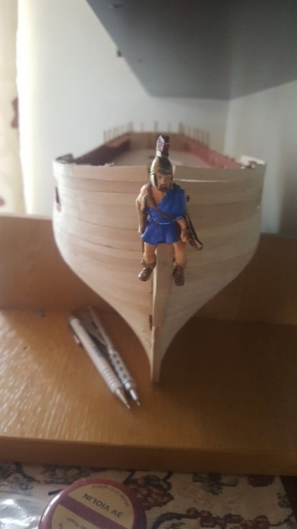
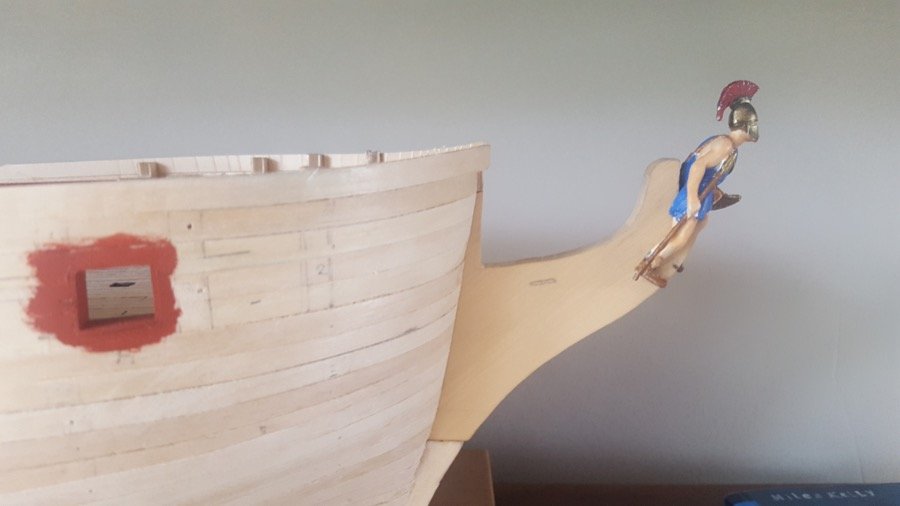
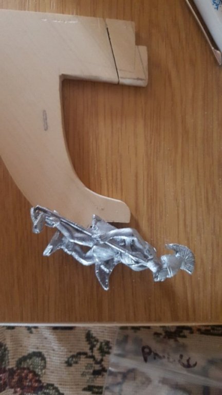
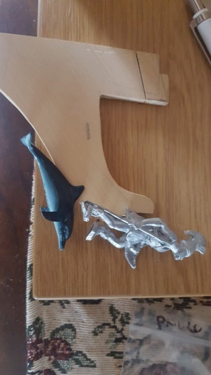
Thanks Jason, Yes, the more I thought about it overnight the more I came to the same conclusion... the figure overall is about 1cm longer than the Diana figurehead, and most of that extra height is above the head (although the legs are longer too). Thankfully Aethelion gives a solution - for the brave! I launched in to remodel the figure to have a dolphin's tale - one fluke on each side of the beakhead... I can't claim credit for the tail - it was part of a plastic dolphin ordered on Amazon. After a LOT of hollowing out using a Proxxon drill/engraver, the figure sat much lower on the beakhead, and was able to lean forwards more. That solved the clearance issue, and then it was "simply" a case of cutting off the legs with a mini-hacksaw, splitting the dolphins tail vertically with a craft knife, and using 1mm wire and CA glue to strengthen the join between the figure and the halves of the tail. There's still a little work to do to make the join invisible, but here's the progress so far (with some shots against the plans to show how the jib boom at AOTS angle should clear the figurehead). Here's the figure with the dolphin tale attached, but no filling / painting. The white is where I've carved the tail back to fit the figure. And after some filling / painting: A bit of work to do to hide the join, but I think I'll make his clothes come down to the join - that'll hide the join more easily. Oh, yes... and I got two more gunports lined... onwards and upwards! Thanks for all the advice, likes, and encouragement. Rob
-
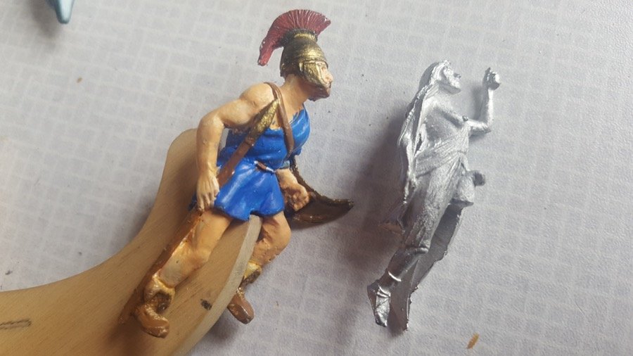
I couldn't resist hollowing out the slot for the beakhead and putting some paint on Aethalion today, along with his buddy... let's call him Acoetes, as per the captain of the same ship that was overtaken by Bacchus in Ovid's tale. Here's the result so far... (with the Caldercraft-supplied Diana figurehead next to it for comparison) And his buddy, Acoetes... standing guard. Now... back to the gunport lining on the port side. Two down - twelve to go!
-
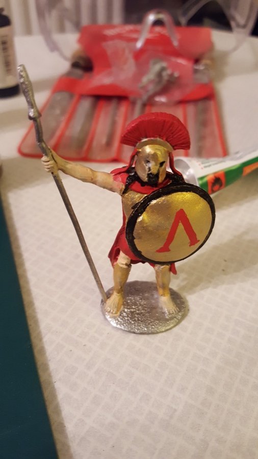
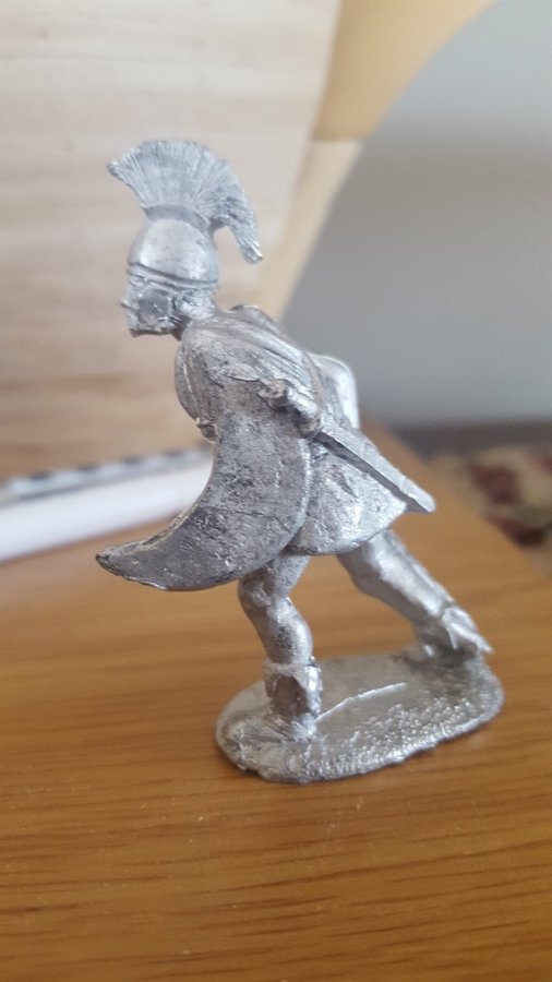
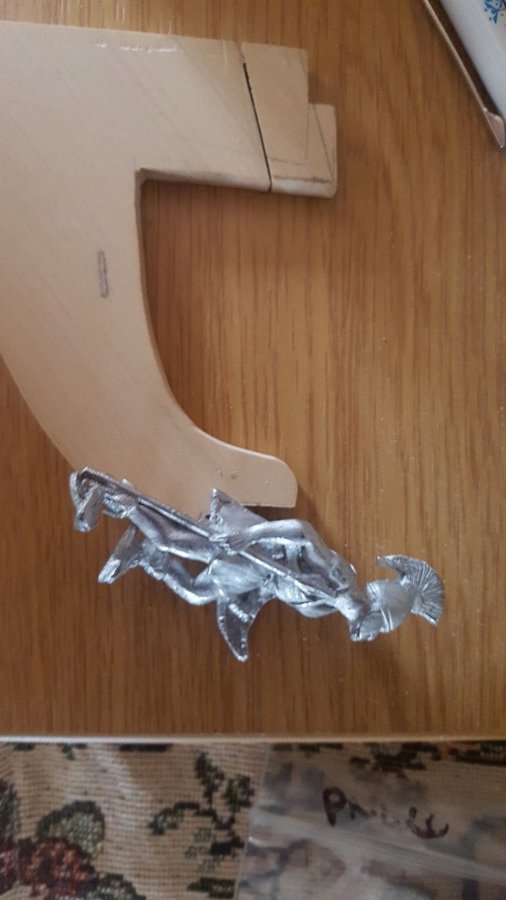
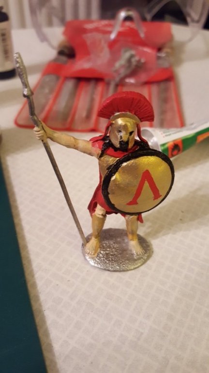
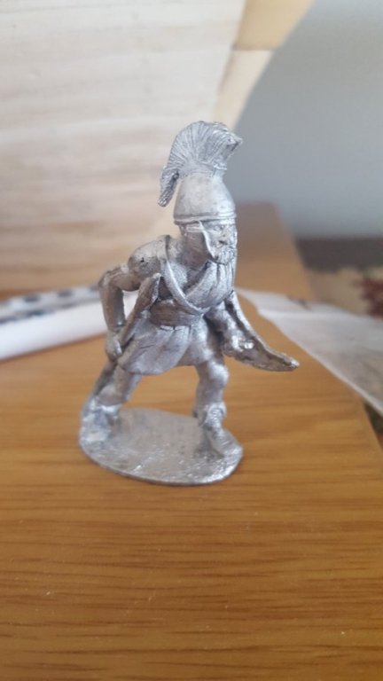
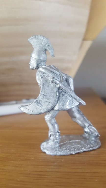
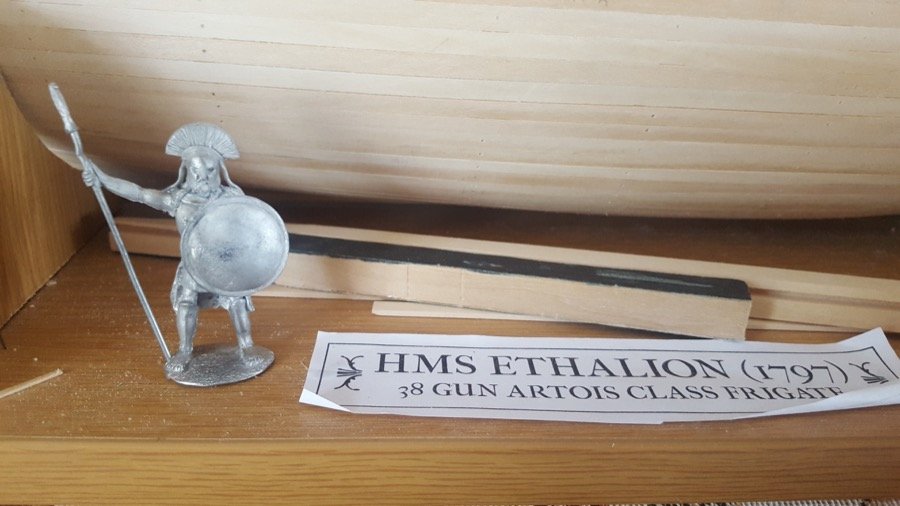
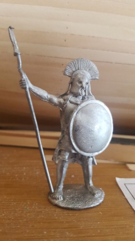
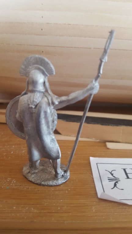
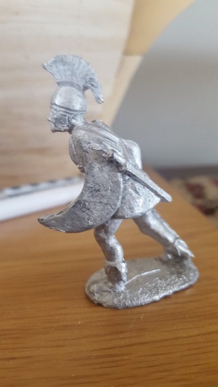
Okay - so I said I was feeling a bit jammy, because I'd had a cunning plan about figureheads. I know enough about my own abilities to know that I'm not about to carve / sculpt a figurehead out of a block of wood or fimo or (insert your medium here), and choosing to model Ethalion instead of Diana meant that the kit-supplied figurehead wasn't going to work! (Ethalion was a bloke for starters, and then he (was) turned into a dolphin!).... so... back to the internet to pursue a solution. And I think I have one. You can let me know what you think. It's a UK based website called http://www.irregularminiatures.co.uk/. Just to be clear, I don't have any relationship with these guys other than this transaction, but this transaction was as good as I could have asked. It's a simple payment process where you email the address on the site and let them know which figures you'd like (I chose the 54mm figures (red links at the bottom of the home page), Greek Peltast with javelin and Spartan Hoplite - it's the Peltast who'll be gracing the bow of Ethalion... they were £3.75 each, which is a steal! You can get them painted, too if you want. Anyway - I ordered on Wednesday, and they sent a paypal link for payment, and they were waiting on the door mat on Monday when I got home from camping. Here they are literally as they arrived in the post without any further cleaning up at all. And after I did a little basic surgery... with the boxwood beakhead insert for Ethalion... And next to the dolphin I'm intending to use to replace the feet and show the beginning of the transformation that Ethalion underwent... (shouldn't have argued with Bacchus!). I shall move his left leg back a little and cut out his back a little to allow him to sit better on the beakhead, but I think it should be doable. For those of us who aren't up to creating our own figureheads (at least, for the model we're building today), perhaps this will be of help Happy building Rob
-
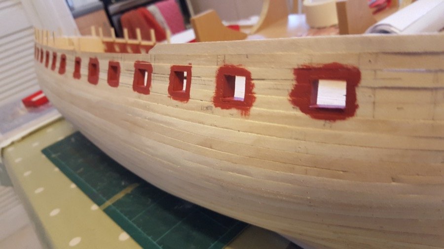
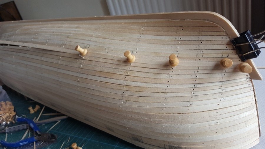
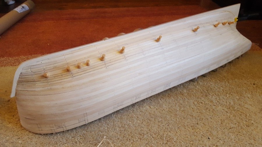
A small update today. Starboard gunports are all lined, now. I've put a first coat of red ochre on as well. Pretty pleased with how it's going. On to the port gunports now, but I'm off on holiday first. I wanted something that required far fewer tools while I was away, so I've ordered a Shipyard HMS Mercury (the 1:96 paper version) - having opened the packet, I've realised I've bitten off a massive chunk that's going to be a job to chew. We'll see how it goes... It'll be interesting to work on similar ships in such different materials. I'll make Mercury as an admiralty style model, unrigged. She's much smaller at 60cm, but will still be a fair size rigged, and there's only so much space in the house In the meantime I'm feeling jammy because I've found a wonderful website with some greek figures that I hope will allow me to make up an Ethalion figurehead (half greek warrior, half dolphin)... If it turns out as well as I hope, I'll share the site. Watch this space! Anyway. Here are some photos of progress on Ethalion. These photos show up quite how much work I need to do on the first planking before I start putting on the second. That's it for now. Rob
-
Thanks so much for all the likes and encouragement. And you're very welcome Hamilton. Not much to update, but a little progress on lining the gunports. This is a time-consuming process, but it makes the gunports look so much neater it really is worth the time and patience. I'm thrilled with how it's turning out, and once I've finished this side, I'll put on a couple of coats of Caldercraft Admiralty paints red ochre to see how it looks. I need to protect the deck first, though. You can see in the photo directly above that I haven't trimmed the inside of these gunports back yet... I though that job would be a bear, but actually it isn't proving too tricky with a little patience and some sandpaper with some wood behind it to give some support. Happy building! Rob
-
Thank you Albert. I've been quietly following your beautiful Naiad. It's a true masterpiece!
-
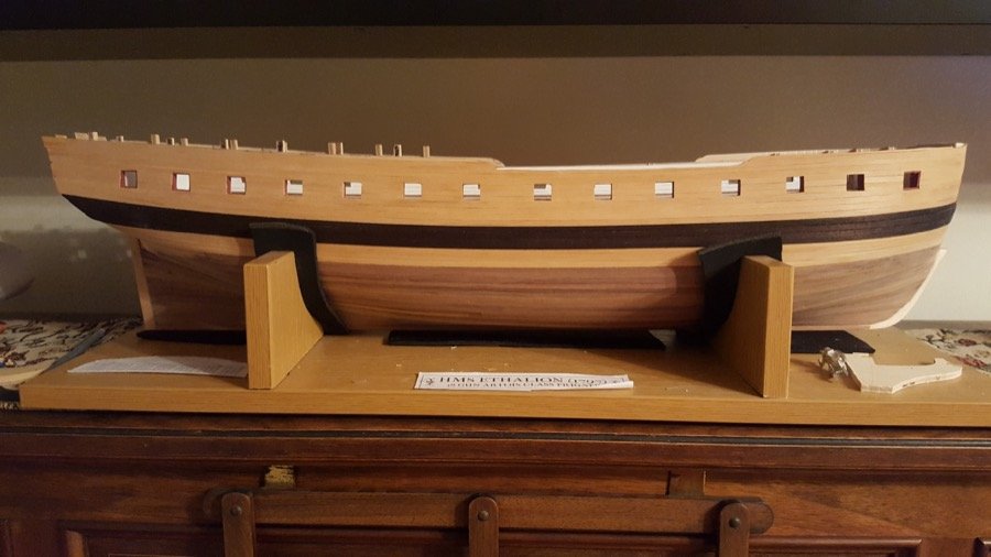
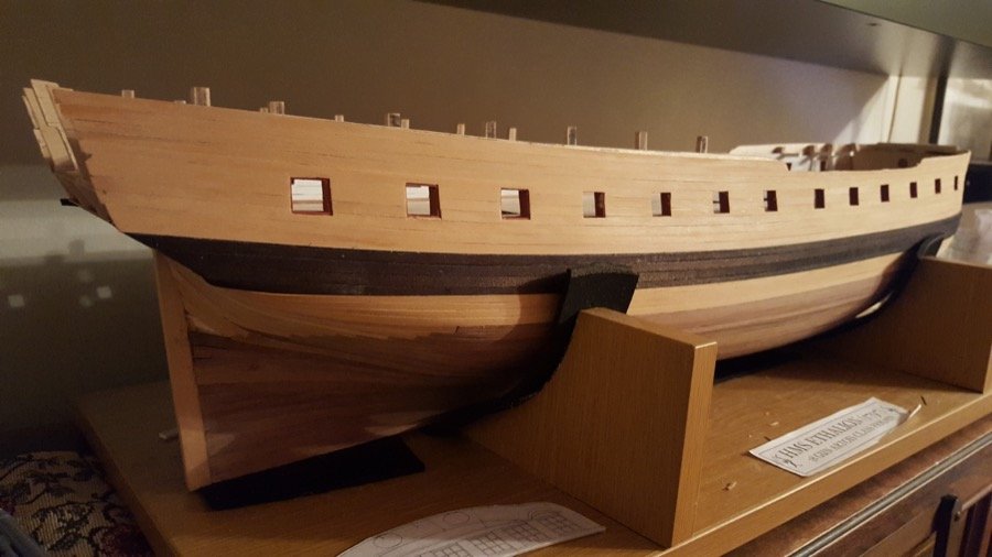
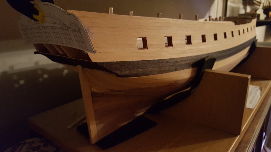
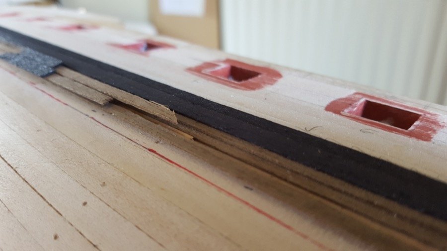
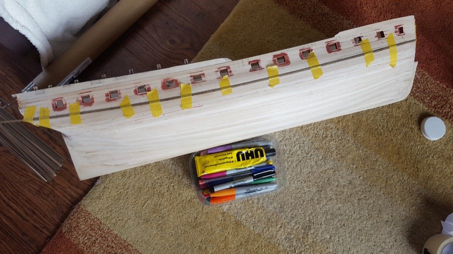
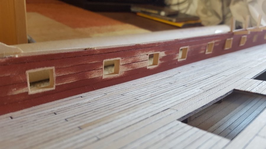
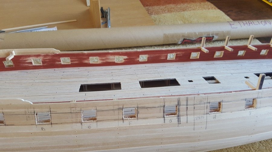
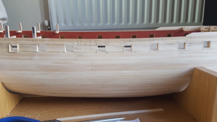
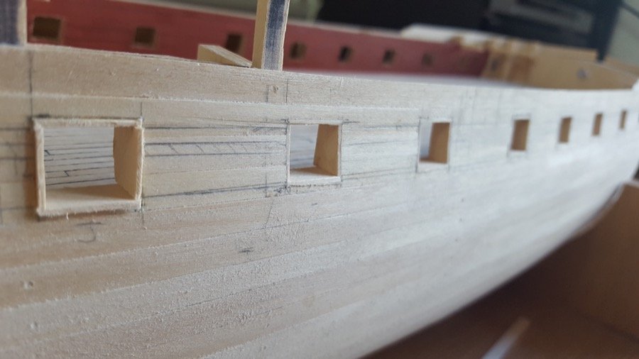
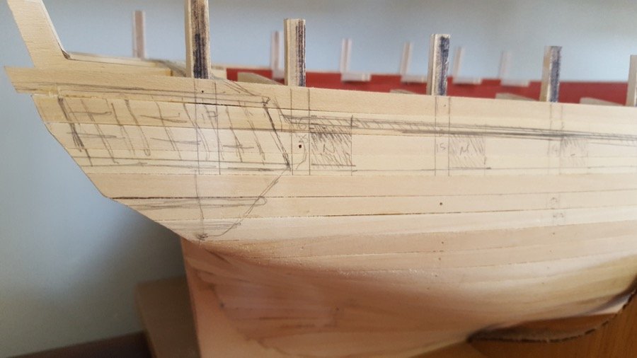
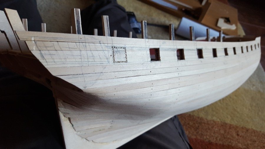
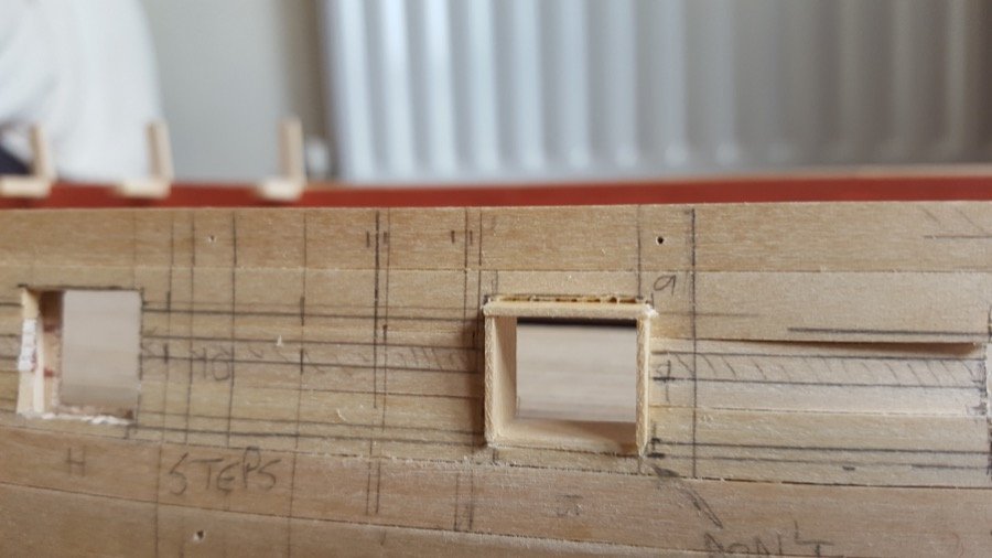
Gunports (all 28 of them!) Having finished the first planking (phew!), I got out the AOTS plans, and the Caldercraft plans and measured and double-measured where the gunports needed to be. I wanted the gunports to be where they were on AOTS, which meant that some of the heights were going to be out for where the gundeck is - I'm happy enough with that, as those gunports will be well hidden under the deck. Given that I'm going to be looking at the outside of this model and not the inside, I want those ports to be where they ought to be. That means a lift of anything up to about 5mm towards the bow and stern. In those places, I'll work out something to do with the gun trucks to get the barrels up to height - whether they'll look okay a little raised, or whether I'll need to raise them up somehow, I'll work out. That's the downside. The upside is that the beautiful sweep of ports goes up to line up with where the galley windows are. Hopefully(!). I figure we're talking about little booster-seats for the guns to sit on towards the far-stern end and forward two guns that'll never be seen by anyone. In retrospect - and building this again, I would build up the gundeck to be the correct height! But that's a woulda for the next model. Anyway - Here's the progress along those lines... Closing up the port side first planking: Marking out the gun port positions with stern galley And then taking my heart in my hands and starting drilling (a new drill from Proxxon made all the difference with this - it would have been a very painstaking process otherwise!): I've also begun to line the ports... (literally just begun!). The ports are drilled out as 16mm wide x 14mm high, then cleaned up and lined with 1mm x 10mm maple to bring them down to 14mm x 12mm. The maple is my own stock left over from the planking. I decided to use this wider stock as it makes lining the sides easier. They can be put in straight up and down as they have the extra width to accommodate this. And that means every cut is 90 degrees. I decided against leaving the sides that join against frames unlined, as I felt this would be less tidy. It's just a little bit more effort in a job that's going to take a _long_ time To aid trimming the ports I made up a sanding stick that was long enough to go through the opposite port on the other side of the frigate. This helps keep everything lined up between inner and outer skin of the hull. I'm also realising that maple is really hard, and perhaps I slightly over-engineered the inner skin on this one!
-
Apologies to people who couldn't see the few pictures on this log. I've moved them from photobucket to MSW, so there shouldn't be any problems. (I've learned my lesson.) Hope to have more progress to report here soon. I haven't disappeared. Just paused this while I learn more skills with the Ethalion. Thankfully the wood is patient
-
Just finished uploading all the previously-photobucket images to MSW. Apologies to anyone who couldn't see the pictures. And every best wish to any who are setting out to build this wonderful model!
- 39 replies
-
- 5
-
-
- royal caroline
- panart
- (and 1 more)
-
Apologies to those who looked for the pictures and found them missing. I had been using Photobucket, but lesson learned. I've moved the pictures all onto MSW, so there shouldn't be any further problems.
-
Not sure whether anyone will flick through this in the future, but I've just finished moving all the pictures off photobucket and onto MSW's servers, so they're all there should you wish to take a look
- 76 replies
-
- 2
-
-
- caldercraft
- finished
- (and 1 more)
-
Hi Jason. Thanks for your kind words. I am enjoying this build and having other build logs of cc's Diana is so helpful for ideas and encouragement to kit-bash and change things as I go. I feel rather like I'm standing on all your shoulders to get to where I am! Looking forward to seeing the next update on HMS Jason. All the best Rob
-
Wow. Those pieces fit together beautifully! Thanks for sharing how you went about making them. I hope to follow in your footsteps.
-
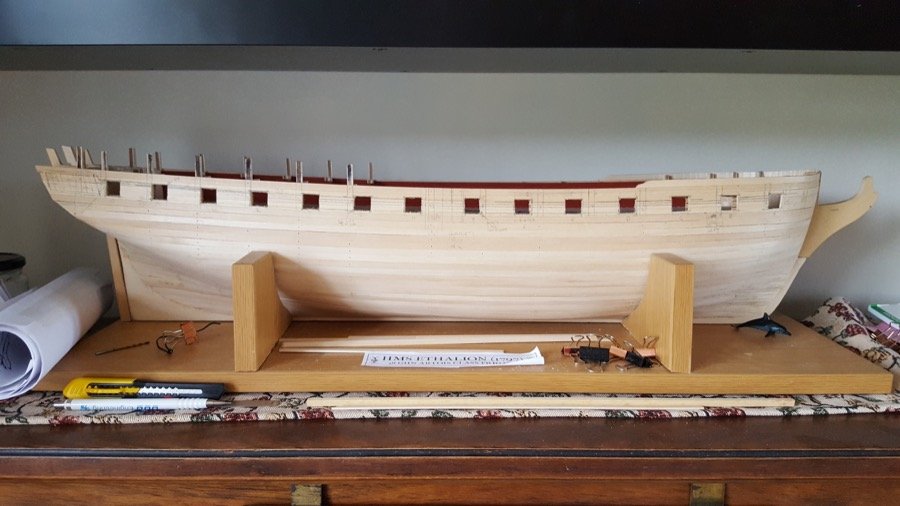
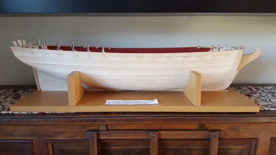
A brief update... and a little milestone! I finished first planking on the starboard side... Now I'm working down the port side. And here she is on her new stand - not perfect, but it's nice and solid, and it'll do for building purposes. Thanks for looking in and the likes and encouragement
- 275 replies
-
- 16
-