robdurant
-
Posts
843 -
Joined
-
Last visited
Content Type
Profiles
Forums
Gallery
Events
Everything posted by robdurant
-
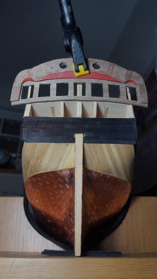
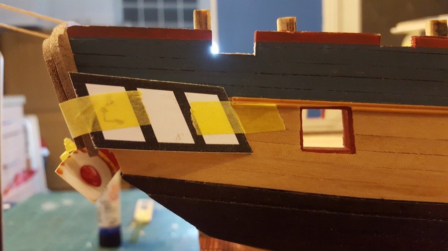
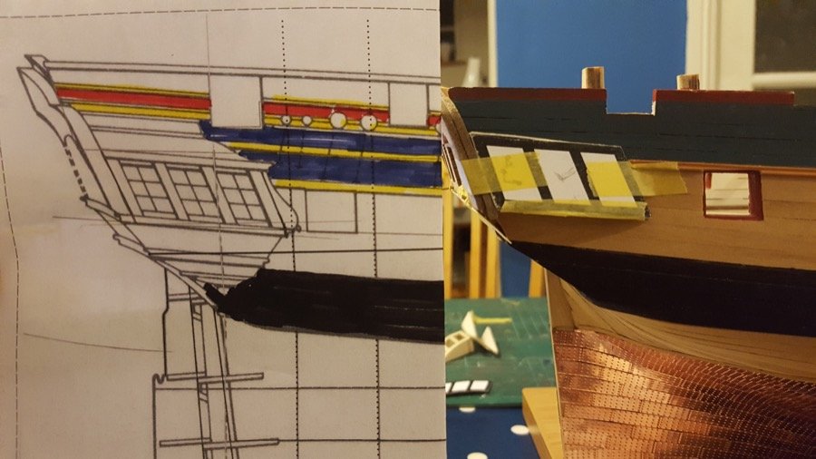
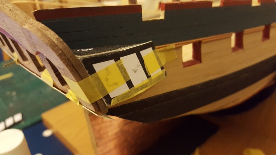
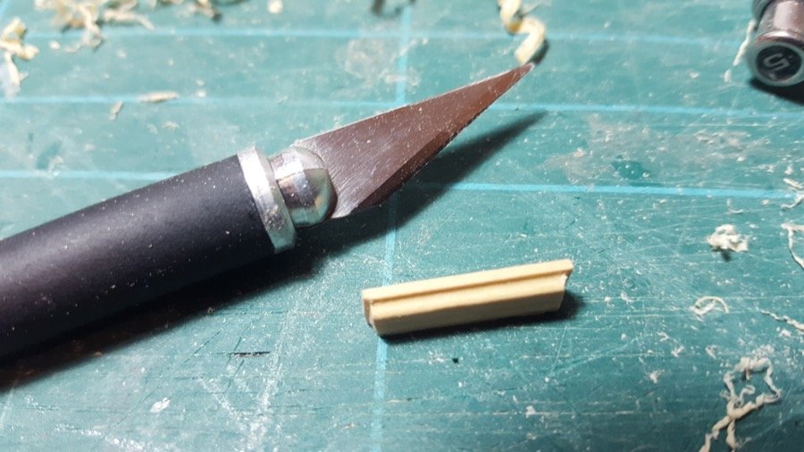
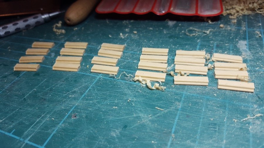
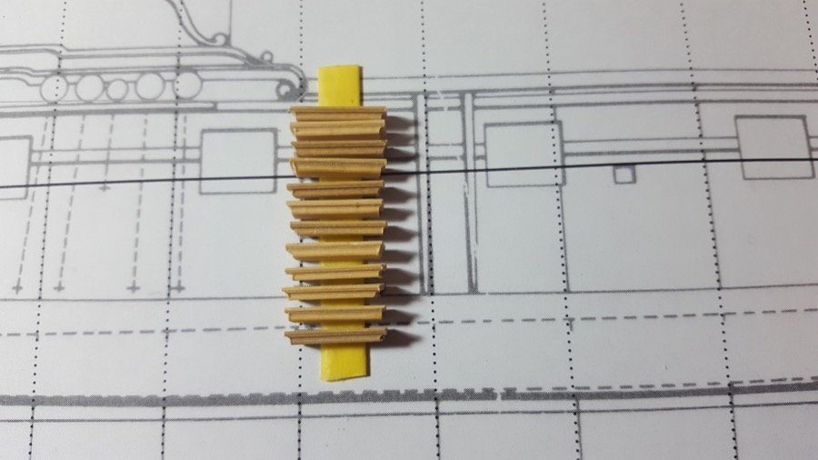
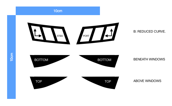
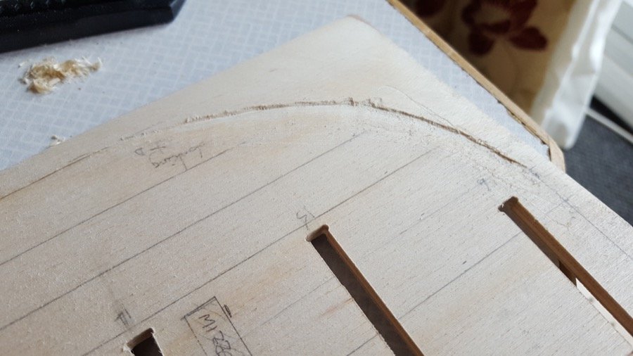
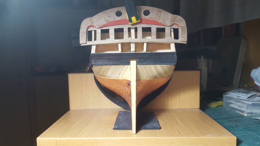
 To gently ease myself back into working on Ethalion after flu, I installed the first decorative rail along the port side to match up with the starboard. I also used the scraper to create a reasonable supply of decorative rail that will hopefully be enough for the rest of the hull sides and transom. All this was 2x 1.5mm maple. Now, I'm biting the bullet again and getting on with the quarter galleries - I think these have kind of scared me - they're complex, and very visible... So. A good few hours with a computer (Apple Pages), the Anatomy of the Ship diagrams, blown up to 1:64, cereal boxes, scissors, and masking tape... it took a few versions, but here's where I'm up to... Version 1: Swoops down too much - it doesn't maintain the line from the gunports... Version 2 was better... It doesn't look like it, but this took a gentle curve, such that the centre of the panel is lower than the outsides - about 1.5mm across the length of the arc. Here's a comparison with the diagram (although they're not lined up perfectly) I've also put the top and bottom templates in on this photo... The masking tape along the bottom roughly mirrors where the trim will go along the bottom of the gallery - and I'm happy that this seems to line up with the sweep of the ports with a slight lift by the stern, as per the diagram. Also, looking from the stern quarter, the windows match up nicely with the stern lights. And here's the templates I ended up with... I've added a ten centimetre measure vertically and horizontally to check if my printer was behaving and actually printing 10cm as 10cm - turns out it's about 9.96cm when printed. I could compensate for that, but these fit on my model. Also of note, is that these are to fit the scale width stern transom I've made according to AOTS, not to fit the kit transom. The AOTS version is considerably narrower. ethalion_quartergalleries_templates.pdf As an aside (and here's the job I'm avoiding, because I don't want to mess it up!) - here are the steps I fashioned from boxwood with a scraper, files, and patience... I'm happy with the steps, but now they need to be fitted to a hull side with a slight tumblehome... I think I know how to do it, I just need to be brave and get on with it... I don't have any power tools such as a sander with angled bed, so I've made a jig... but I'm struggling to hold onto these little blighters and get them down to the right tread depth, with the right angle to stick out horizontally from the hull... Anyway - quarter galleries first, and then back to the steps. Wow - those close-ups are brutal - they look okay to me in real life! These are going to need some cleaning up... Happy building to you all! Rob
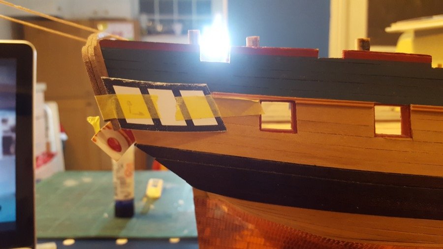
-
Thanks OC. I'm well on the mend now and even started building a jig to sand the angles onto the backs of the steps on the hull sides. More progress soon.
-
Sorry for the lack of updates... I came down with flu, and I'm just getting back to "tired-but-normal-ish"... spent a week having no choice when I slept - it just happened, and I knew it had happened when I woke up again. Anyway. Looking forward to jumping in and getting on with Ethalion again. Rob
-
Brilliant. Thanks Jason. I'll take another look and update it. The logs are available at The National Archives in Kew. You can get a readers ticket for free and order up the logs from stacks. It's a humbling thing to touch the originals.
-
Looking great! I don't think you can go far wrong with balsa fillers. I find it so helpful to give an idea of the contours of the hull when I'm fairing the bulkheads, and it helps with adhesion for the first planking where the hull has the greatest curves, too. The other thing I do is mark the edge of the bulkhead with a sharpie - that way when I'm fairing if the black disappears completely, I know I've started to reduce the overall shape of the bulkhead. Hope that makes sense. You can see the black line left along the sternmost edge of the forward bulkheads in the photo below...
-
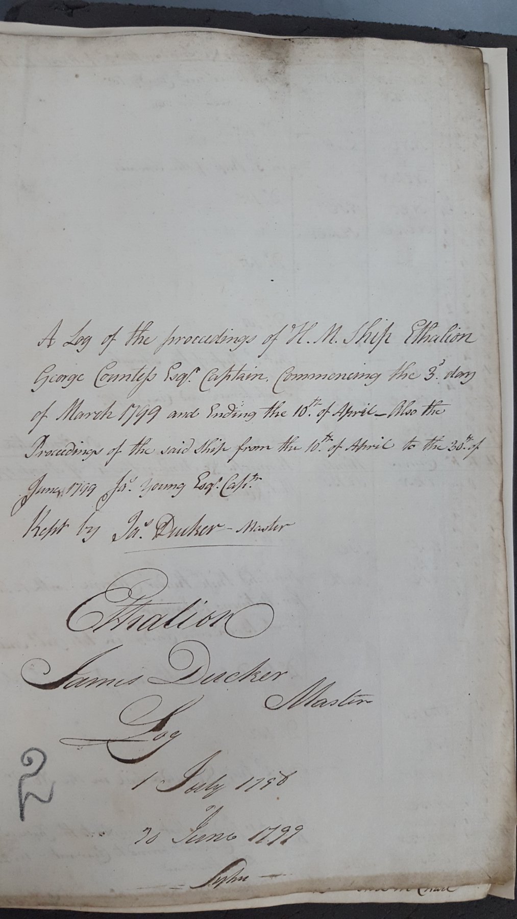
Okay - I promised I'd pass on the logs as I managed to transcribe them... Here's the first year of master's logs. EthalionLogTranscription.20180330.pdf I've tried to maintain the layout of the documents as far as possible. Happy reading.
-
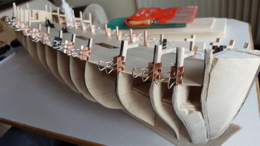
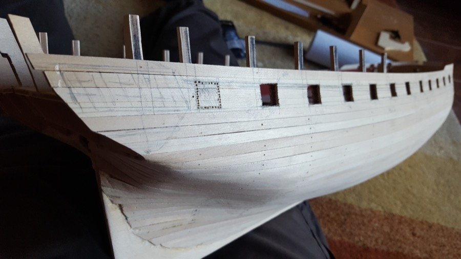
Hi Jobbie, Thanks for starting this log. I'm half way through building a Caldercraft kits too. I've brought a cushion for the pew, and look forward to seeing this one come together. Looks like you've made a great start. It's surprising how thin the stern needs to be to accommodate all the planking, isn't it. If you're still wondering how you can get it slightly narrower, one option (an option I've seen others use on this site) is to only take the first planking up to the bearding line... This means the part that reaches the sternpost only needs to be planked once (the second layer of planking) straight onto the keel former. You can see the rabbet at the bearding line for the first planking in the first photo below, and the first planking completed in the second photo. I'm sure you'll do a fantastic job regardless. Your previous builds look great! Rob
-
Thanks for the kind words Jason. And thanks to everyone for all the likes. I'm also planning to wait until the quarterdeck is on before putting on the higher rails. I have found it a challenge to visualise precisely where the deck edge Will be so won'tfeel confident I'm putting the top rail in the right place until then. I do want to make up the rails in one go though as if I lost the scraper it would be tricky to make one just the same. I shall scrape them an store them until the right moment. I haven't thought much about the headworks yet other than to keep an eye on where they terminate on the hull. I want to get the stern sorted and the quarter galleys first. My son and I are making two p51 mustangs side by side now... he seems to be having fun but time will tell whether the bug really bites
-
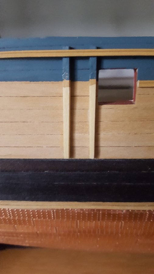
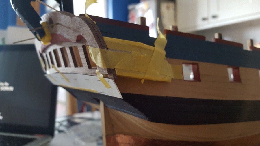
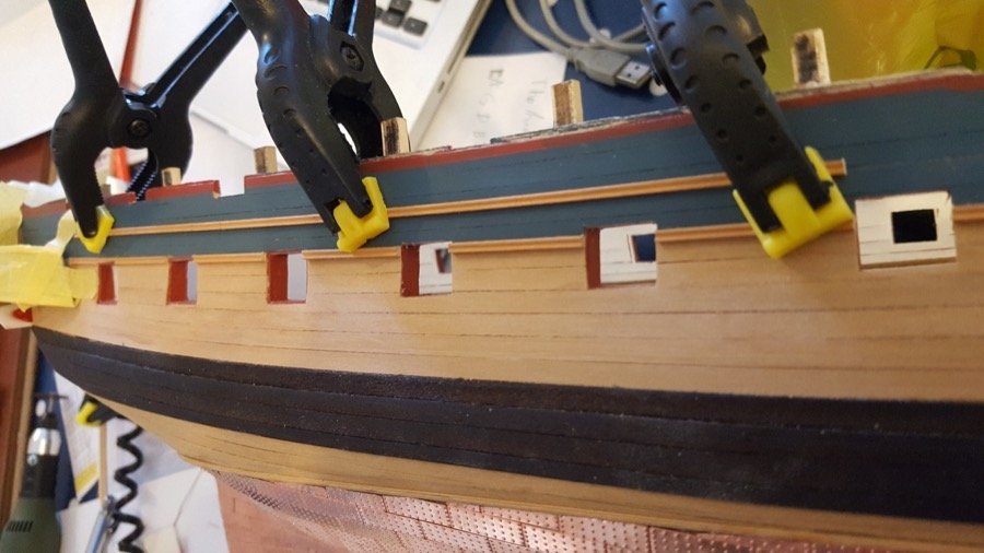
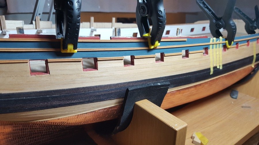
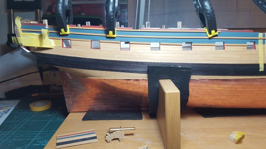
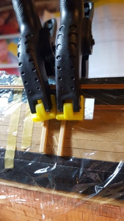
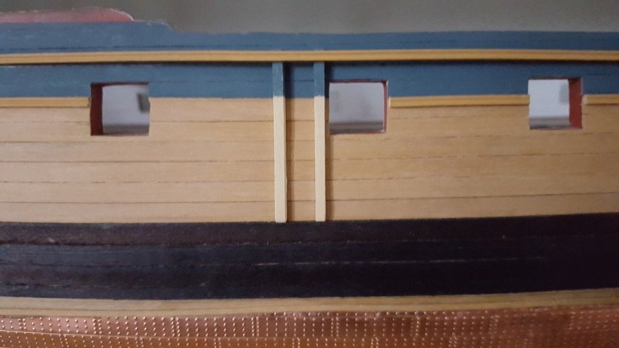
So, I took those vertical pieces off... fenders? - I wasn't happy with the colour, so I used some very watered down Admiralty Paints Yellow Ochre as a wash just to tone them down a little... I don't want everything to be exactly the same colour (that's the beauty of wood, surely) but close enough that it doesn't whack you in the face when you look at it... It looks better to the naked eye - these close-ups are brutal! I took the opportunity to narrow them down equally (to 1.6mm at the bottom), and align them better... the photo makes them look uneven, but the ruler tells me the vertical centre lines are parallel. I also added the paint, although this will need touching up. Overall I'm closer to happy with them. Side steps next. I have a scraper lined up for them. The fenders now...


- 275 replies
-
- 10
-

-
Oh, and I forgot to mention, the profile is 2x1.5mm maple scraped using a custom scraper and painted with yellow ochre.
-
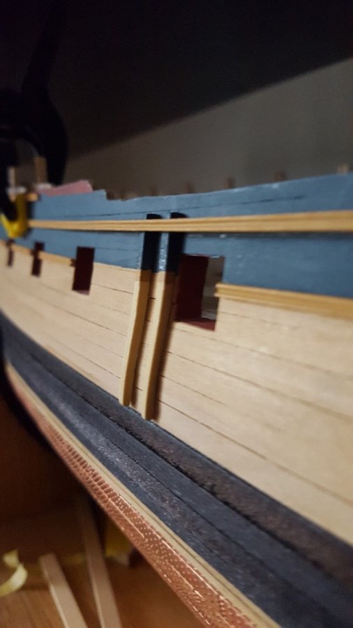
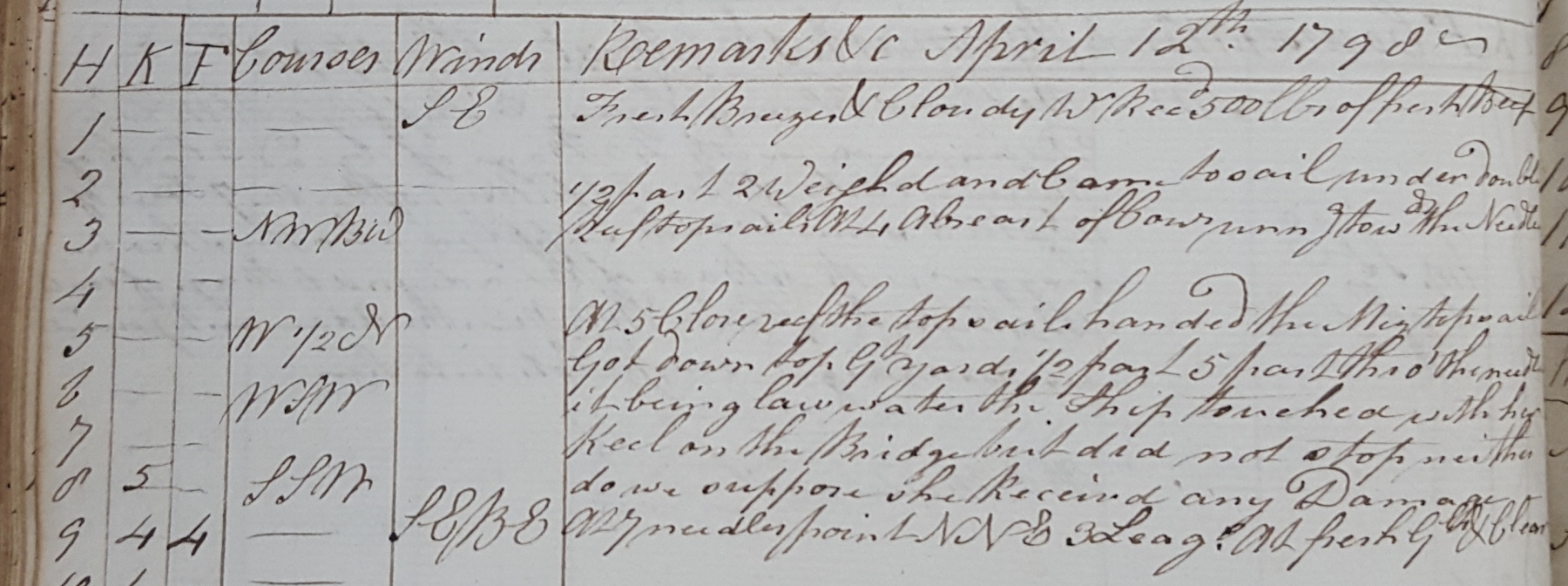
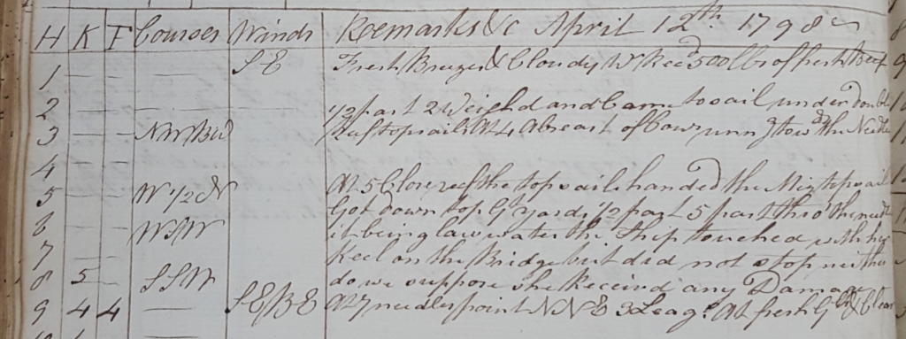
I'm still transcribing the logs for Ethalion - it really is fascinating... They're very matter of fact, recording this sort of thing from Thursay 12th April 1798. HMS Ethalion had just left Spithead and was passing the Needles. I found this description of the "bridge" at the Needles... From the following link (with which I have no connections - just found it googling: http://www.yachtingmonthly.com/specials/pilot-the-isle-of-wight-the-needles-to-st-catherines-point-3161/2 Now, I appreciate I'm no professional sailor, but no matter how professional you are, that's got to be a bit of a heart stopper when heading for a thousand tons of wooden ship bumps along the bottom at sea! Anyway - it all adds to the picture as I begin to detail the hull... Having shaped these strips (don't know what they're called?) I'm not entirely happy with the colour - they are box, but they're much whiter, and look more like maple... I'll see if they tone down, and otherwise might remove them and remake them... we'll see. The paint at the top also needs touching up, and the yellow adding, but I just wanted to get the boundary line marked on before I stuck them in place. The top rail is clipped in place so I can measure up and check how it's all working out. It will be trimmed to go to either side of these verticals when the time comes.
-
Looking really good. As far as the photo rotation goes, there are two ways of rotating a photo on a computer... one is to actually change the file data to be the rotated image (this is a fairly big job as all the compression maths that keeps the file small probably has to be reworked). The second is to just set a parameter in the file metadata (Exif)that says e.g. "display this file rotated90 degrees clockwise" . The second option is much quicker and many desktop computer programmes and cameras use this function... so it will look rotated in your screen. However internet browsers / websites often ignore this data so an image rotated the second way will appear as it originally was. The solution is to find a programme that actually rotate your photos as per the first method. Hope that makes sense. Rob
-
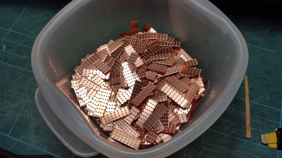
Thanks Zappto. The cut pieces of tile can be really fiddly but the results are worth the pain
-
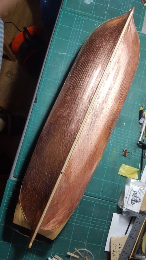
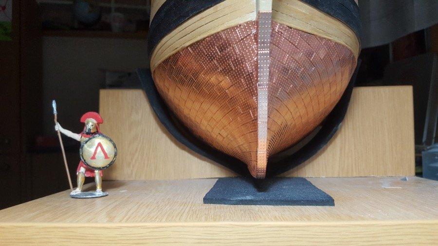
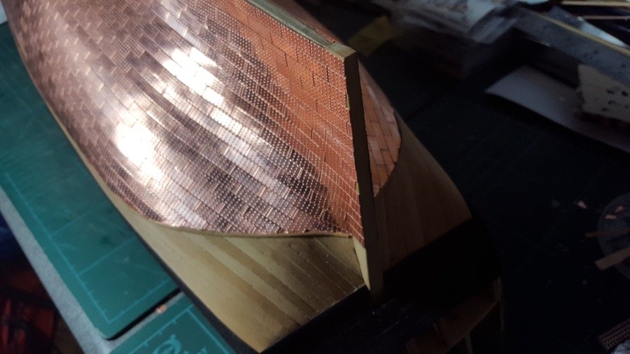
A major milestone! The coppering on the hull's complete! I'll be honest, I won't mind switching back to wood glue from CA. The mask worked really well, though. It's definitely worth paying a little extra for a proper vapour mask (not one of the wood dust masks). I used the following mask... 3M 4251 Maintenance-Free Organic Vapour/Particulate (it was around £22 and worth every penny) I ended up with a fair number of copper tiles left, so Caldercraft seem to have supplied ample spares. I may well go along the keel and tidy up a few of the first tiles I put on... they're pretty easy to pop off if required.


-
That all makes perfect sense.... I wasn't aware that was even an option at this scale but the results speak for themselves. Fascinating. I'll go back through your and Pat's logs and take a closer look. Thanks Rob.
-
Those look fantastic. So helpful to see the way you've gone about making the parts ready to fabricate these parts. Hope you don't mind my asking what may be a silly question... When you say weld, is that tin and lead soldering / silver soldering or another method, and do you add flux separately or use fluxed solder? I've done some electrical soldering, but never had much success with brass parts... perhaps because my soldering iron wasn't powerful enough. Those jigs look really neat, though, and the result speaks for itself!
-
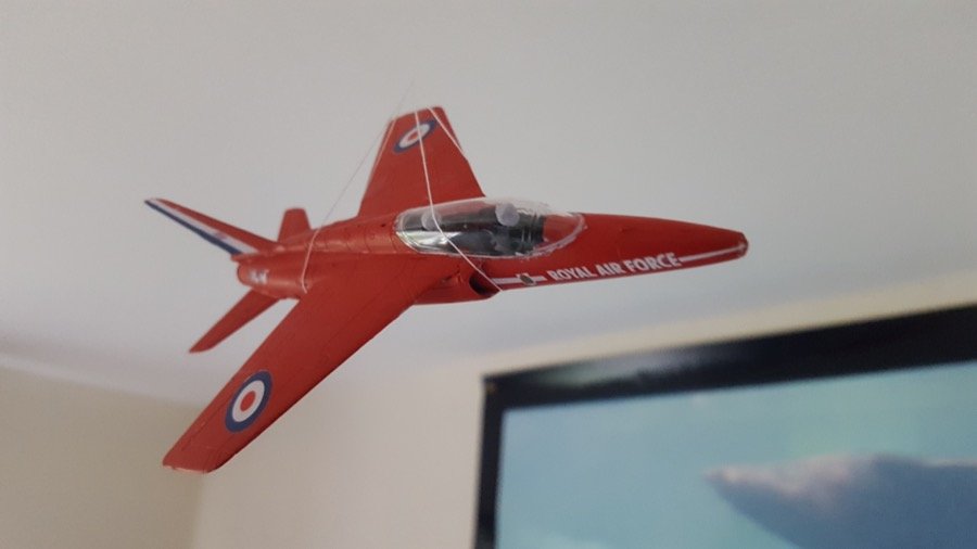
Oh, yes... and here's what my son and I have been working on at the same time His first airfix kit! Not bad for a 7 year old. He's really excited about the second one, now. A DeHavilland Mosquito's in the post. Happy building!
-
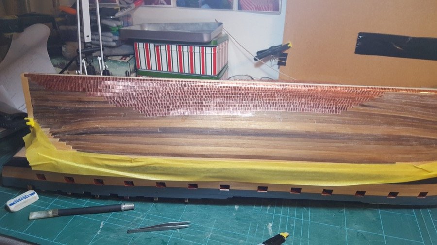
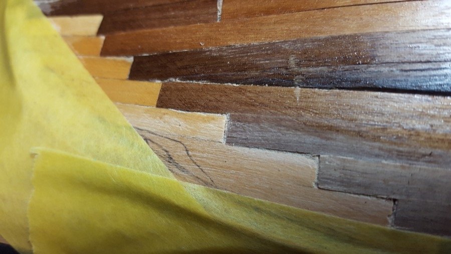
Not much to update at the moment really. The time finally arrived to start the coppering of the Port side of the hull. I find it fascinating the way I tend to get into the groove after a while, and it gets done... I reckon I've probably got about 300 tiles on so far. I put a line of masking tape over the wood that'll be exposed above the waterline, just to protect it from superglue marks from tiles that slip... On the starboard side, I put a coat of black acrylic to seal the wood and give the superglue something to stick to (otherwise it all sinks into the wood and leaves nothing to stick the tile - this reduces the amount of superglue I get through a lot)... this time, I used some matt enamel varnish. It was lovely to see how the box and walnut came up. The first photo shows the difference with the varnish... at the top is the varnished wood, and at the bottom the untreated wood... left is box, right is walnut... (and the grey marks are my pencil marks from marking the waterline ready to put the batten on... this is that tricky bit at the stern where the hull tucks round. I've carried on transcribing the Ethalion logs... turns out Ethalion went to assist the ships of the line the day after the battle of Camperdown, and helped Isis bring her prize home.
-
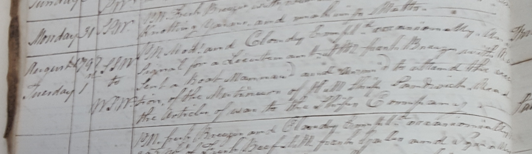
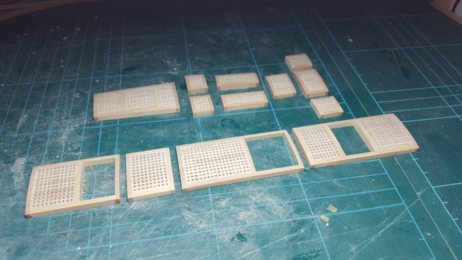
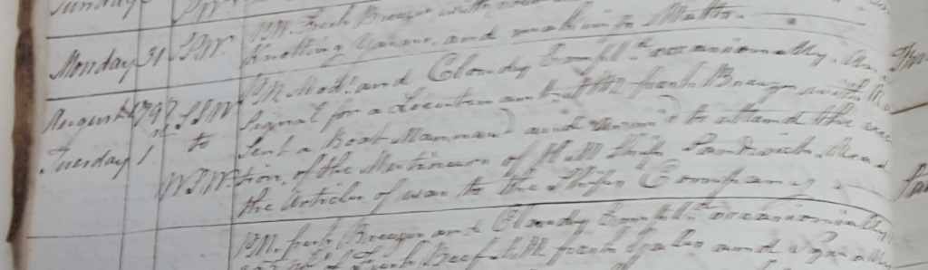
So... I'm working on transcribing the master's logs for Ethalion - a time-consuming process, but I'm finding it really interesting, and the task of reading the handwriting well enough to write it down accurately helps me take in what's being said. So far I'm completely amazed by the sheer amount of fresh beef a Frigate got through! So far Ethalion has taken her maiden voyage to Copenhagen doing convoy escort with HM Sloop Scorpion through some pretty unpleasant weather... the Topgallant masts have been up and down a few times already in only a month or so. The logs start in July 1797, and Ethalion spends a good part of July and all of August in the Nore. One of the things going on at that time is hangings for mutiny aboard various ships to be witnessed... I wonder whether these are punishment for the Nore mutiny a few months earlier. Certainly it must have been a tense time for everyone. For example: Tuesday 1st August 1797 SSW to WSW P.M. Mod’t and Cloudy. Employ’d occasionally. Answer’d Signal for a Lieutenant. AM fresh Breezes with Rain Sent a boat Manned and Arm'd to attend the execution of the Mutineers of H M Ship Sandwich. Read the Articles of War to the Ship’s Company. Sandwich was the flagship in the Nore at the time with Admiral Lutwidge aboard. And below is the original (apologies, the photo I took of this page was somewhat blurry): Anyway - a little progress on the model, too... after a LOT of sanding, the gratings are finished. The row nearest the camera is the upper (gun) deck, and the row behind is the forecastle and quarterdecks... both laid out so right is towards the bow, left is towards the stern. Thanks for all the kind comments and likes. Rob
- 275 replies
-
- 10
-
-
Great idea with the mast collar. She's looking really smart.
- 378 replies
-
- 3
-
-
- t78 norden
- billing boats
- (and 1 more)
-
Wow! You've done a lovely job with this model. It makes a fascinating subject. I laughed out loud when I saw the bucket Glad the pictures were helpful.
- 82 replies
-
- 2
-
-
- naval smoothbore
- model shipways
- (and 1 more)