Beef Wellington
-
Posts
2,249 -
Joined
-
Last visited
Content Type
Profiles
Forums
Gallery
Events
Everything posted by Beef Wellington
-
 Beautiful work there Ronald on the head 'foundations', also really highlight your fantastic clean planking. Great stuff.
 -
The former (Anchor Clinch) is undoubtable the period correct solution, it is also referenced in James Lee's Masting and Rigging English Ships of War.
-
Nice start, looking forward to seeing another fun project come together BE
-
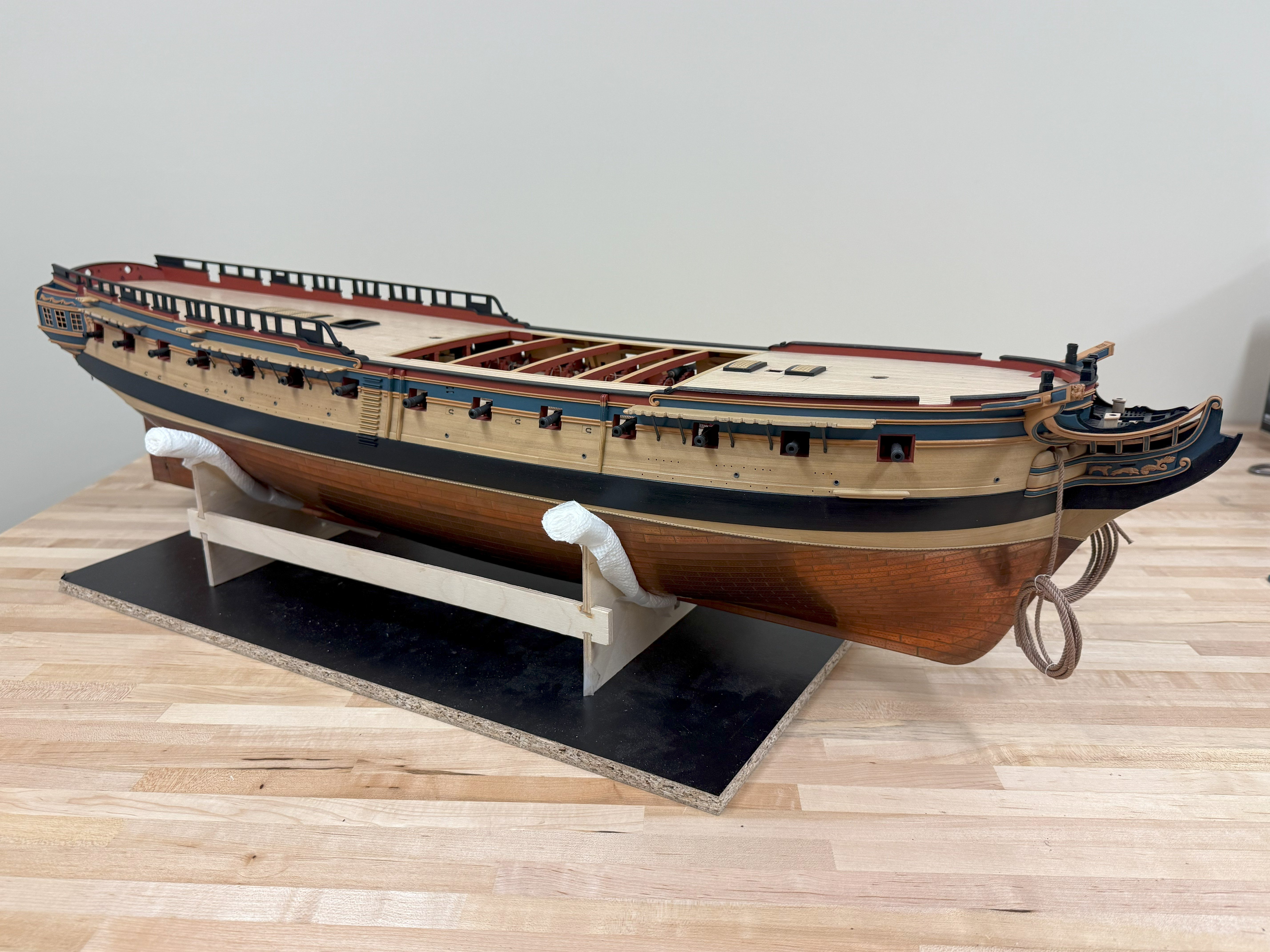
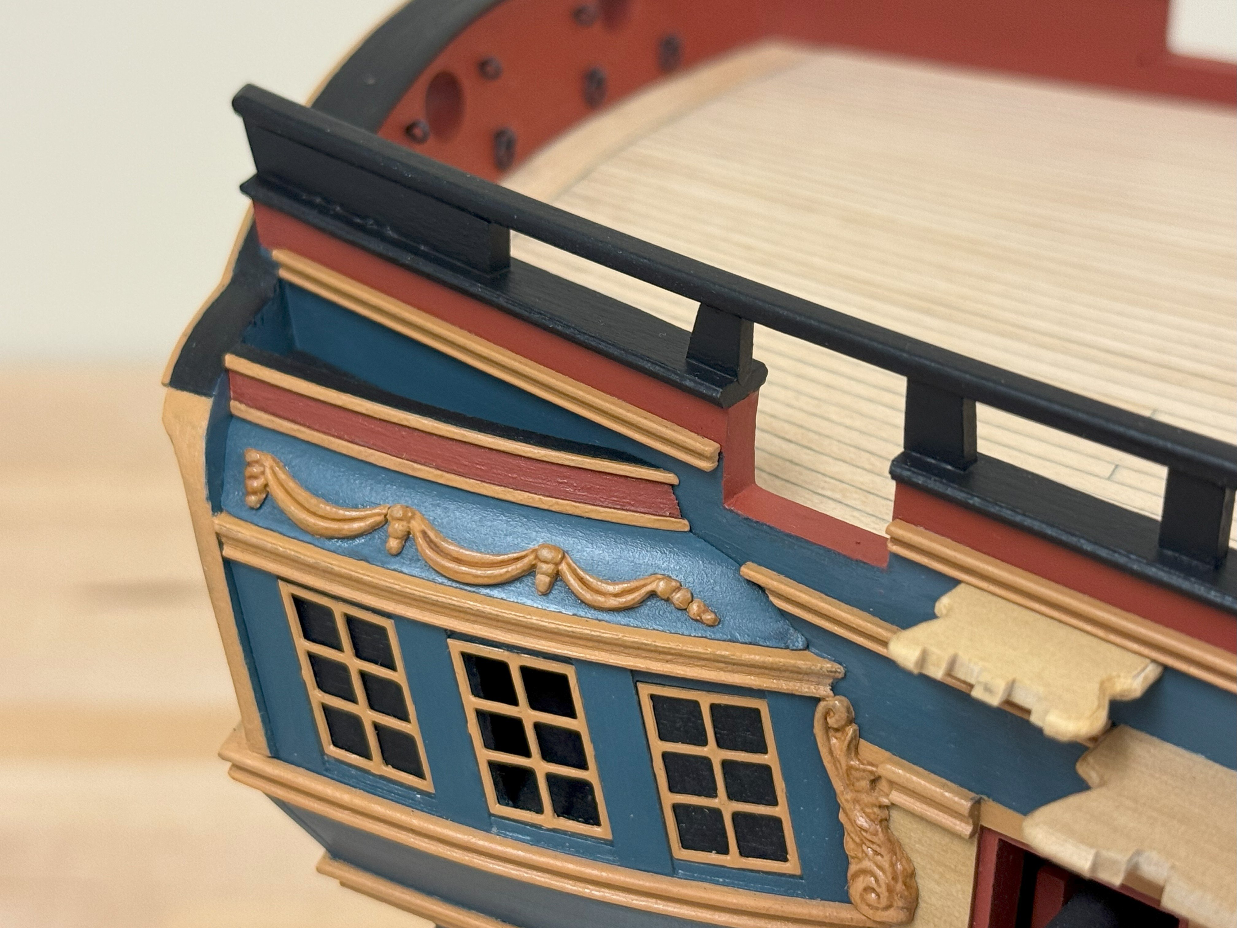
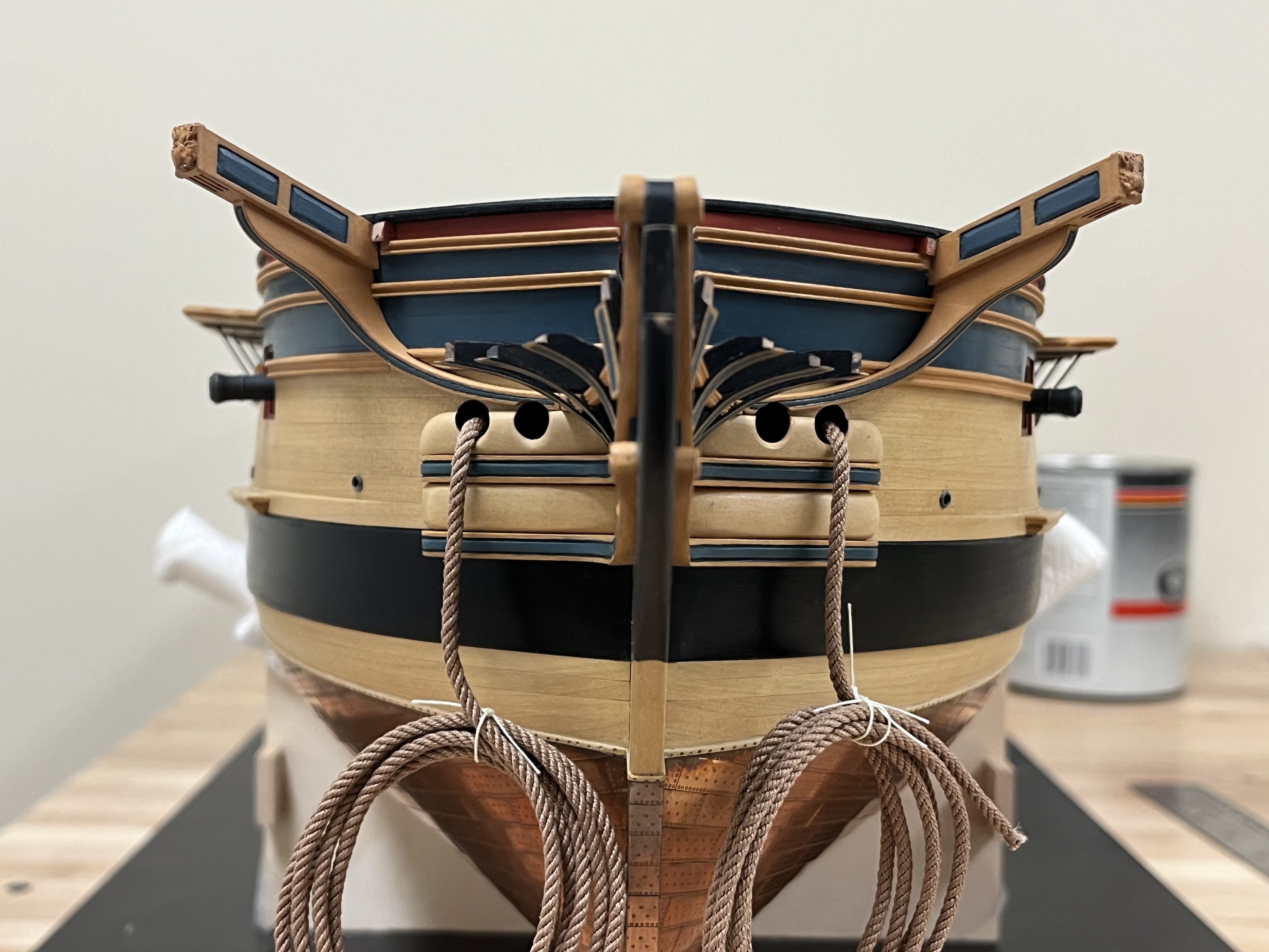
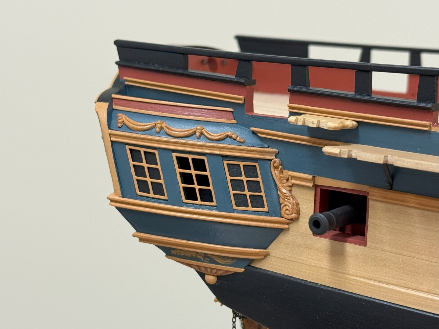
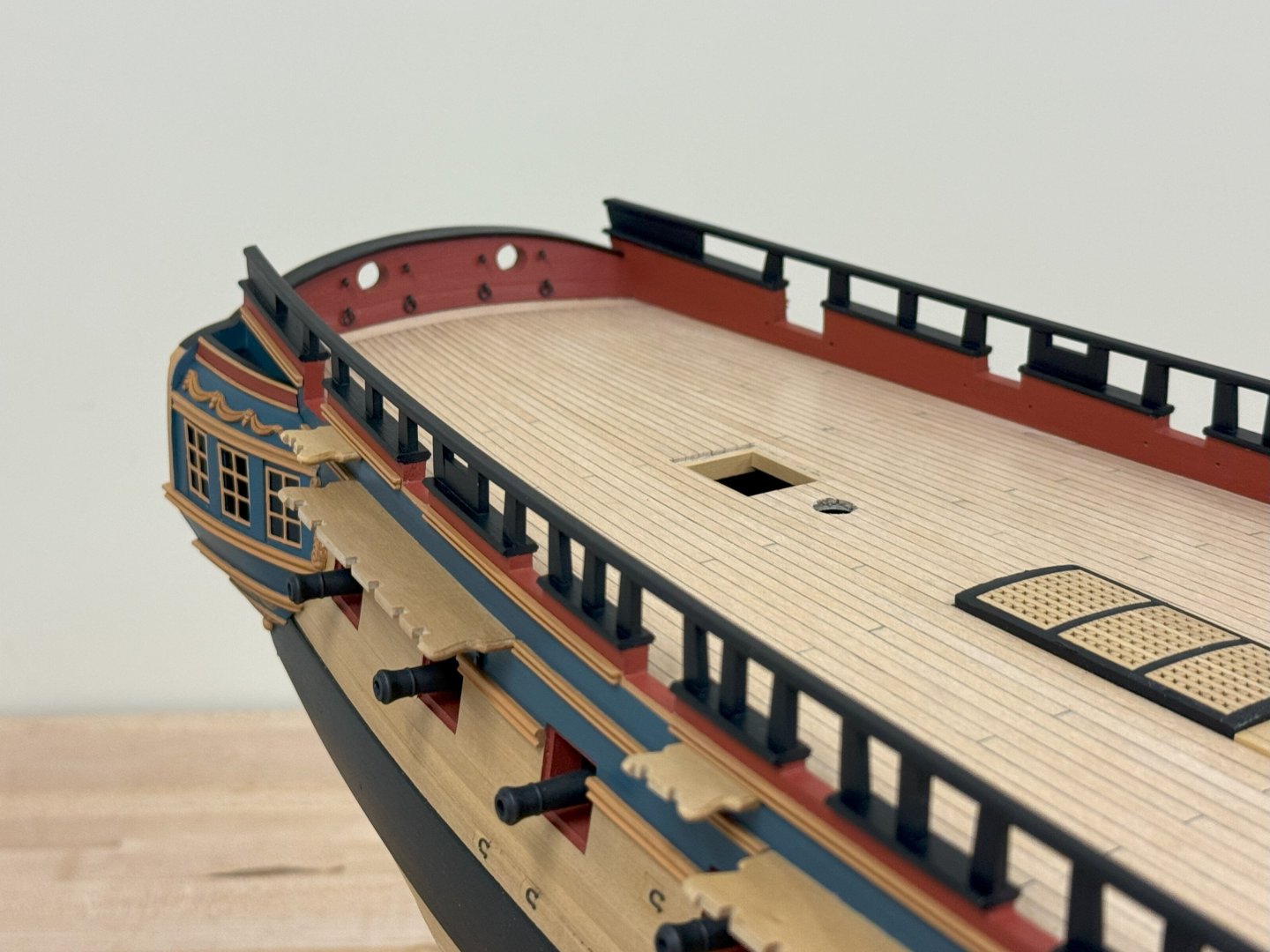
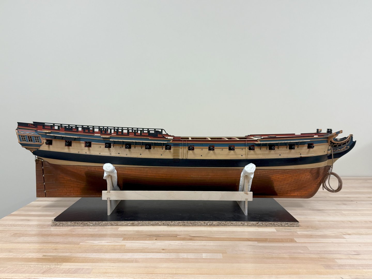
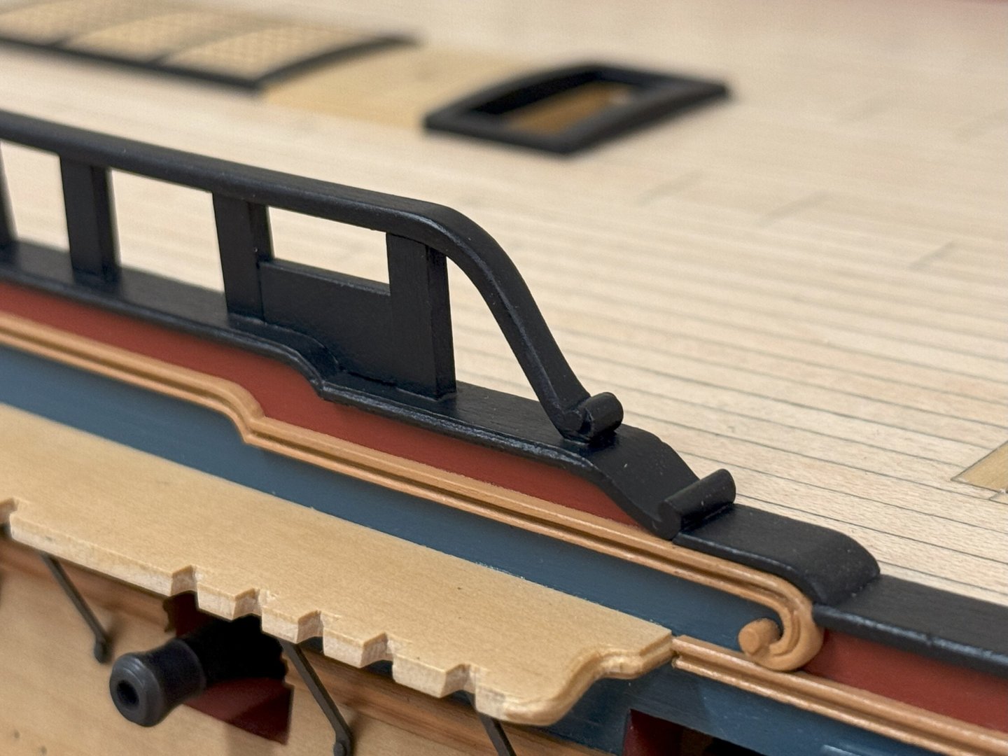
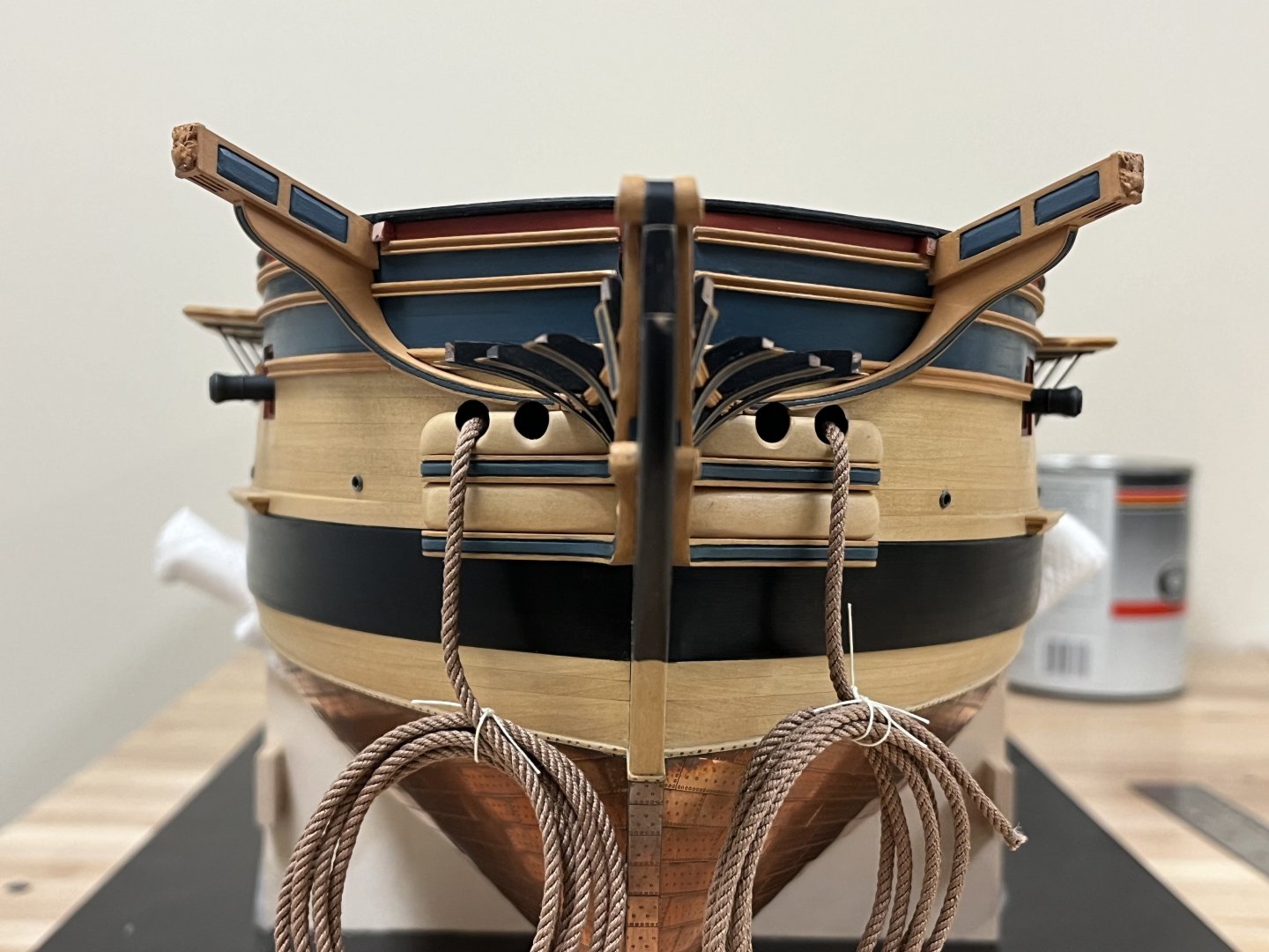
It has clearly been a very long time since last I was here and I hope that people remember me! Suffice to say it has been hard to make any progress beyond a snails pace. I last left off after focusing on the complex bow structures. To keep moving I needed to install the rough tree rail and the various supports as well as the Fretwork to the upper finishing. Dimensions were estimated from plans and contemporary model, and these all seem to vary to some degree. I had held off making the fretworks as I wasn't sure of the approach, and I wanted to get a curved profile. In the end, shaped billets were made to size and shaped, thin 1mm square boxwood strip (which I had hand sanded down to ~0.5mm) was then glued to the upper and lower edges. Once dry, the back was cut away and finished by hand. This is where the piper must be paid for any prior size and alignment estimates- as things stood I'm estimating that this is maybe 1mm shorter than it should be per the various plans and diagrams (4mm vs 5mm), but this was necessary to sit appropriately. Unfortunately, my progress was so slow making the rough tree rails that I neglected to take photos. These were cut from 2mm boxwood following the profile of the hull and were 3mm wide. The curved for'ad sections were made separately using a similar technique as taken for the decorative rails and then joining to the main rough tree rail. This follows the sheer of the deck, rather than the wale, so a template was made to ensure that these were positioned correctly. The timberheads were then added using 2x5mm pear strip., because these are continuations of the frames, they need to be perpendicular to the keel. There seems to be a huge amount of small variation on how these were constructed and captured on plans and models, and a variation even between the plans I have for HMS Jason showing these and the various Artois class models. The template was once again used to ensure the consistent height above the deck. Much of this process required fine adjustments using the Mk. 1 eyeball which seemed to take a considerable amount of time. In the end, I drew inspiration from model 1794-3 illustrated on page 19 of the AOTS Diana book. This has 2 curious semi-bulkheads installed in the timberheads, as well as being solidly built up at the stern. I have no idea what these are as I haven't seen them anywhere else. The mizen and main backstay stools have also been glued into position. Finishing up with some overall shots of where things stand (The quarter gallery lights are not attached, but were placed to get a sense for proportion when finalizing the fretwork)


-
Will follow you closely on this build, the lines of this ship are quite pleasing. I have seen others struggle with some aspect of this kit, I hope those kit failings have been corrected and this is a pleasant build for you.
-
Hi David, I hope I didn't add confusion, these are the things I find endlessly fascinating. Its always hard to explain shapes on 3D curved surfaces but I think the post below the master Chuck on his Speedwell model illustrates well, it shows a planking template to apply to the hull. The rise of the wale flattens off slightly and is probably most visible when viewed from the front, and the same being true for the line of the top timbers as they approach the centre.
-
Hi David - the placement of the wale is indeed challenging. A fact that is maybe completely obvious to many but only hit me after a lot of looking at plans and models is that there are essentially two curves/sheers that are followed. The deck/gunports, and the upper hull/wale. The second is most important to get correct as the top of the hull, lines of planking, molding and the wales should all essentially be parallel. Once seen, this is something that can't be unseen! If you are happy with the line of the hull at the bow, then I would suggest using that as a basis for aligning the wale (basically measuring down equal distances from the top of the hull). When viewed from the side, the wale should have a gentle flattened 'S' shape. The same alignment is true at the stern, but if you are building with the raised bulwarks, then this is much easier to accommodate - the top of the raised bulwarks follows the sheer of the deck, the moldings follow the sheer of the wale. Good luck!
-
Best wishes Rob, I'm sorry my hiatus delayed responding to yours!
-
That is just beautiful planking!
-
Awesome progress! Question on the galleries, do you think you will be using the resin/plastic galleries in the final version? It feels a little our of keeping with the other wonderful wood of the model.
-
Your planking looks spot on, very nicely done. I'm pleased to see that you appear to have filled in the stern a little to allow the planking to sit nicely against the sternpost, think you will be much happier with that result. The shaping of the plank ends in this area can be challenging further up the hull, definitely not something to rush. Looking at what you have done so far, sure you will encounter no major problems. You have a wonderful model coming together here.
-
Looks like the perfect balance to my eye...1 too few, 3 too many 🙂 The different paint tones really catch the eye and enhance the whole, very much to my taste as well. Wonderful model you have there, very well done indeed!
- 648 replies
-
- 3
-

-
- Indefatigable
- Vanguard Models
- (and 1 more)
-
This is definitely going to give the Caldercraft Snake/Cruiser model line a run for its money! Maybe this will show whether CC have completely lost interest in new static kit development when some of their established legacy models comes under direct competition.
-
Love the picture of the stern Christian, the more muted monochromatic approach is definitely to my tastes as well...the Norman knights don't look quite so...Norman! Good luck moving forward, but you already seem to have the major challenging elements completed successfully.
-
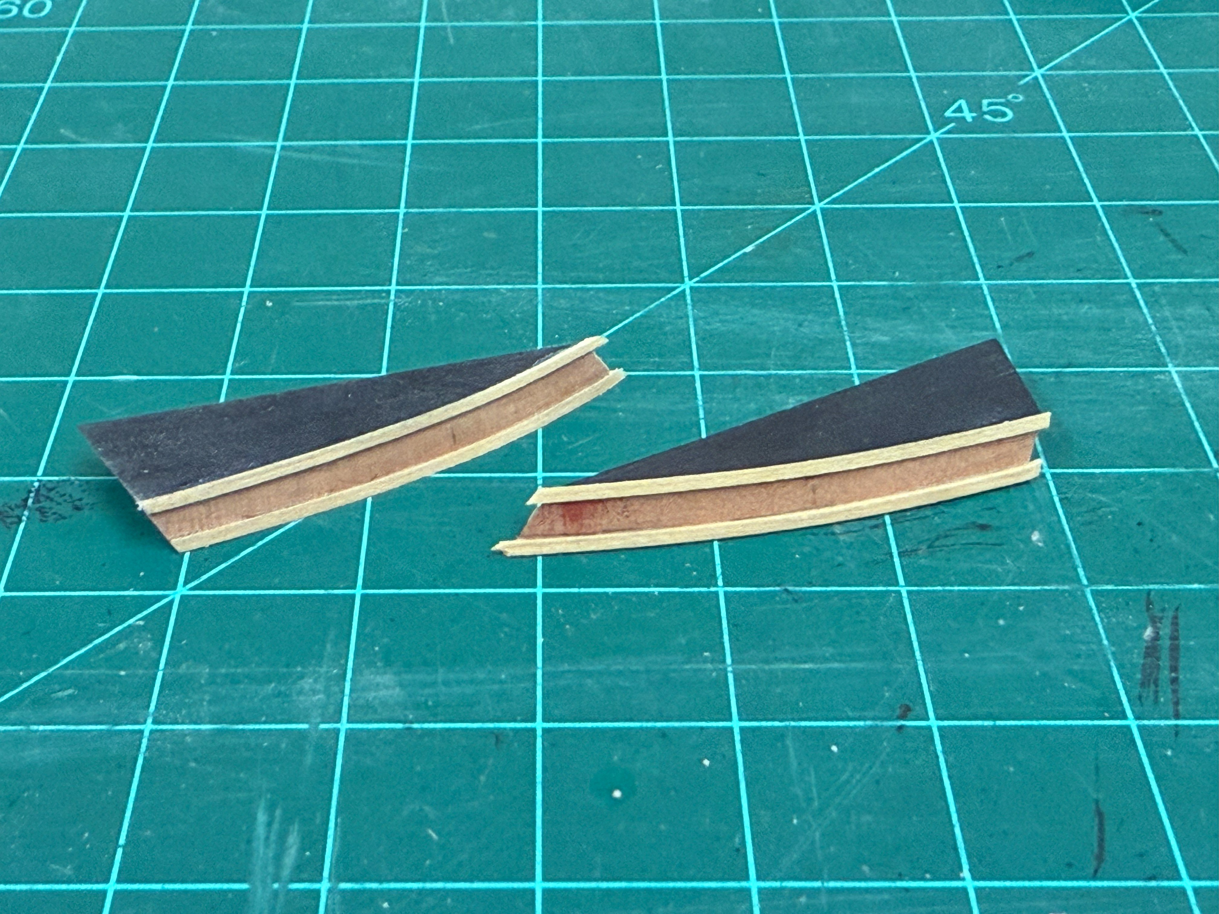
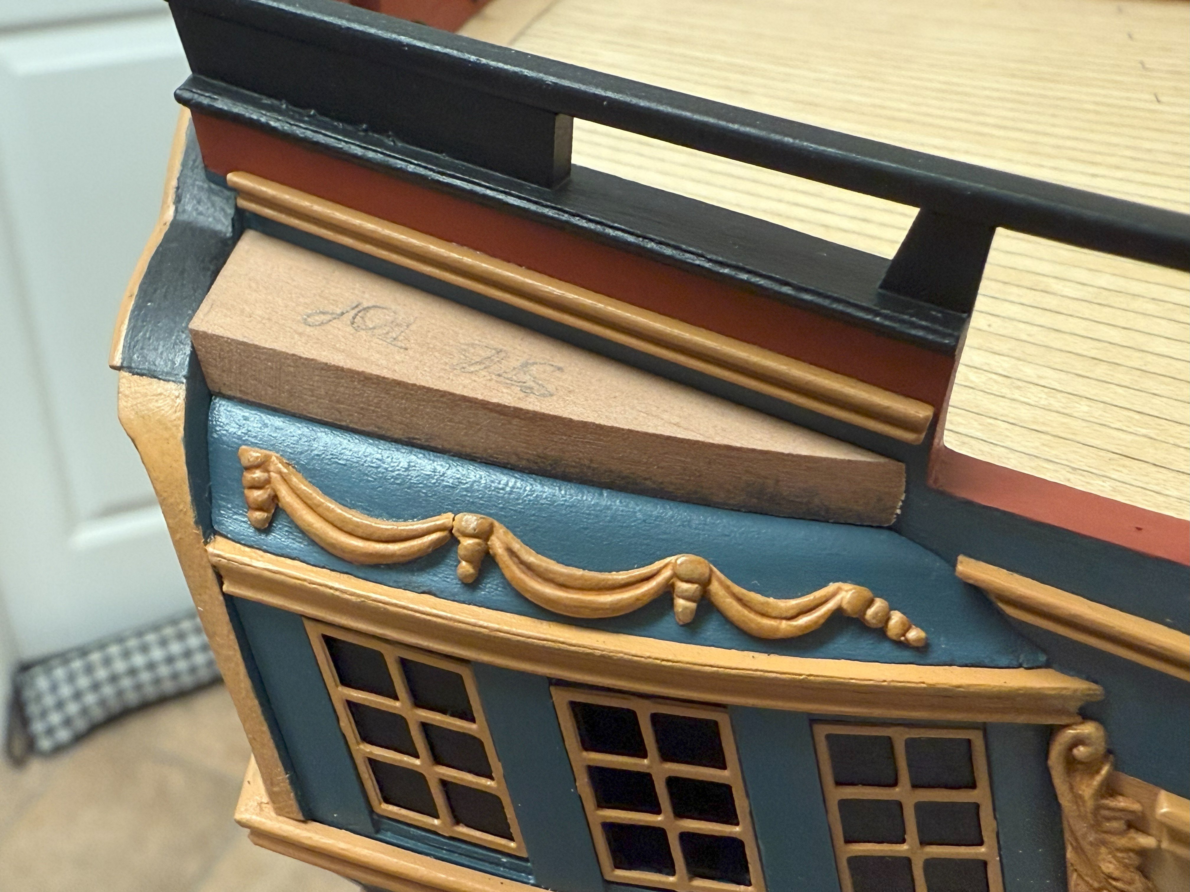
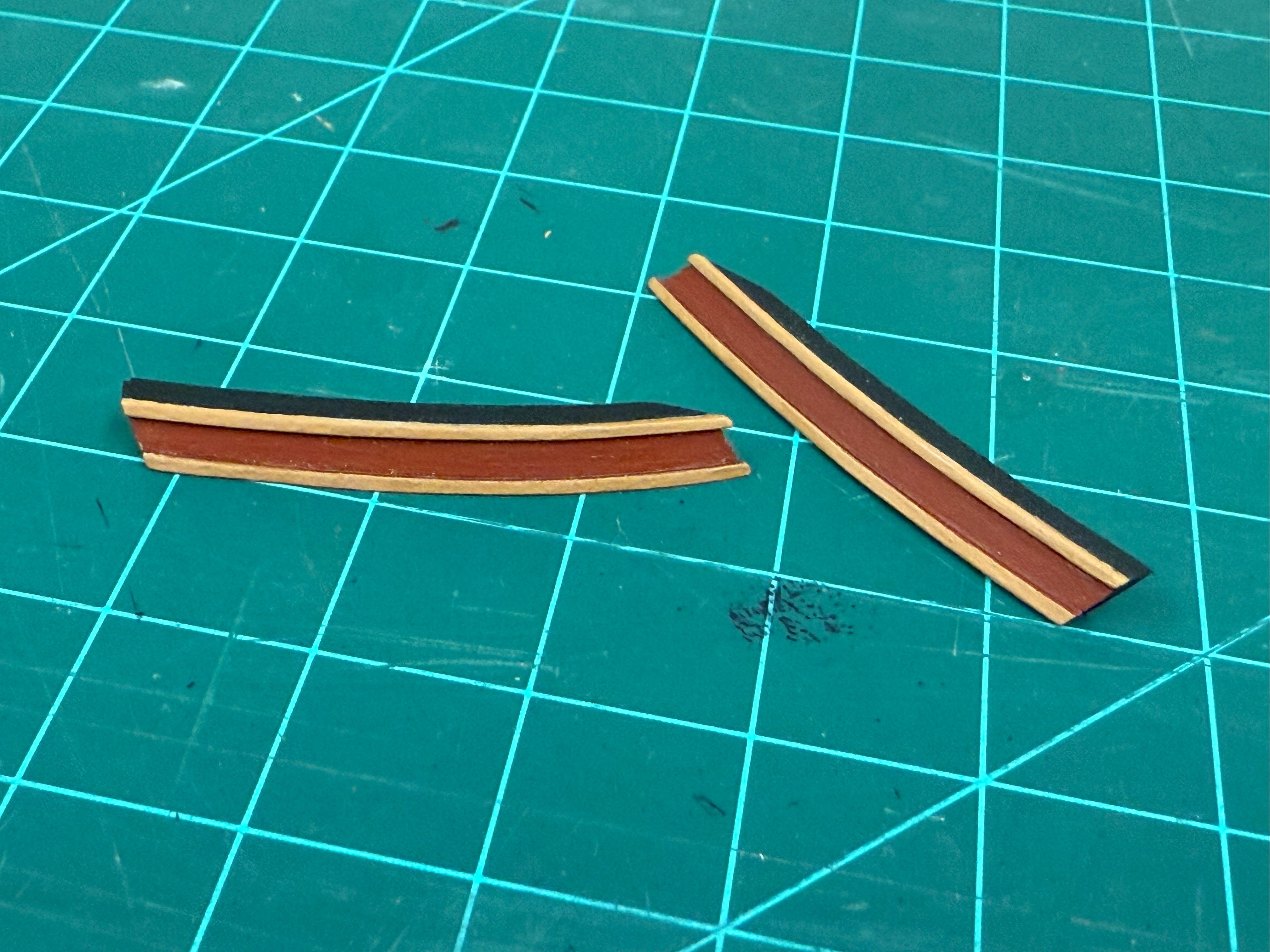
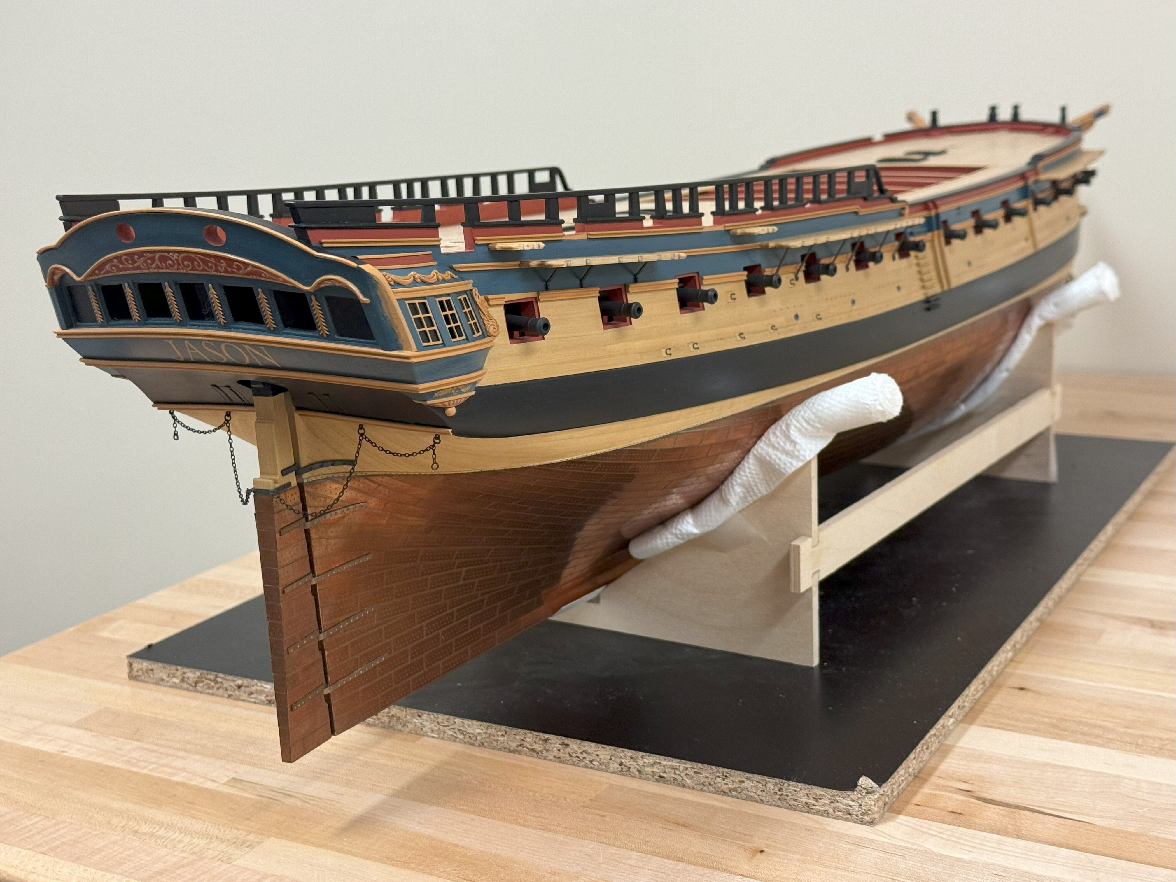
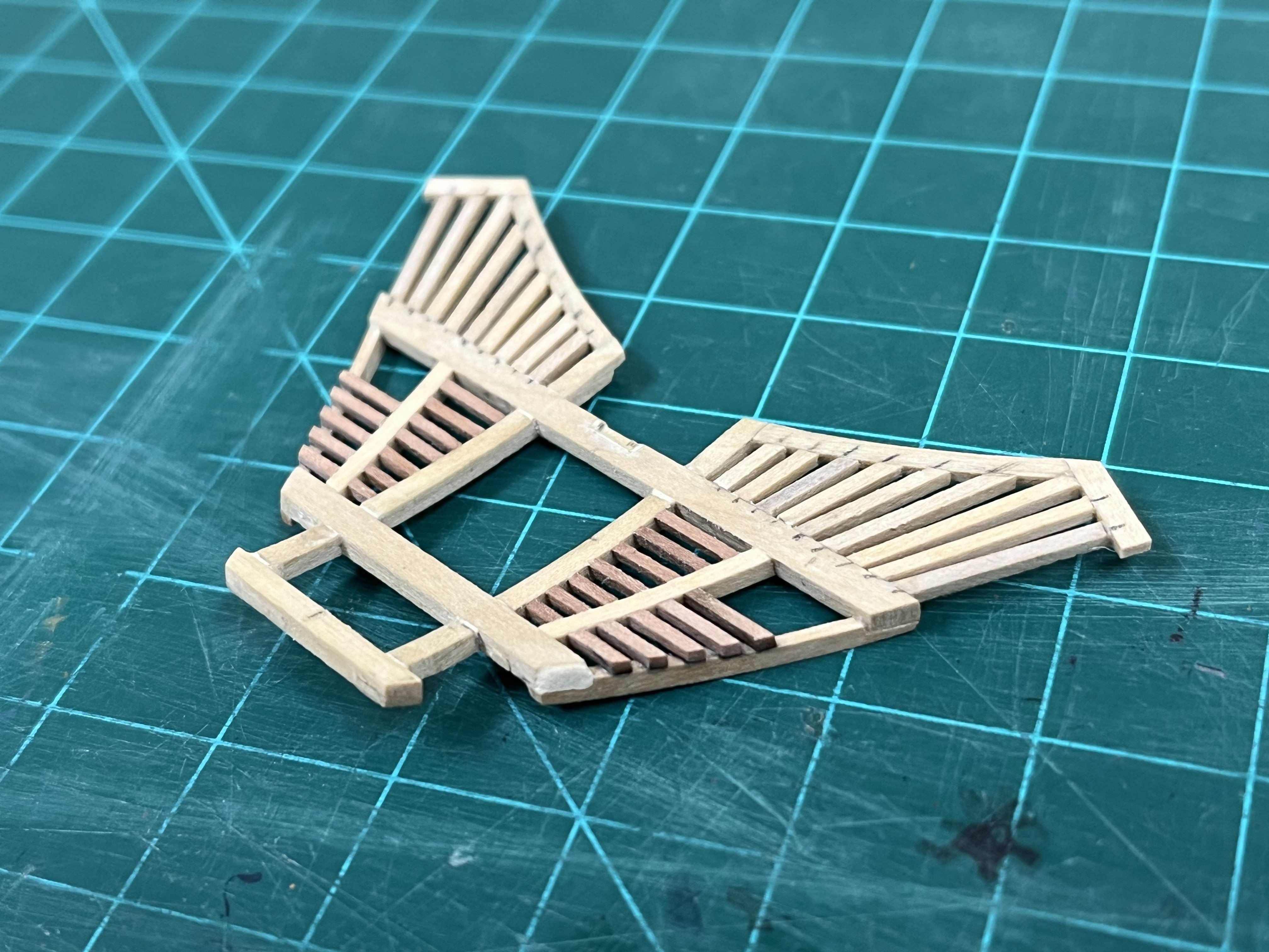
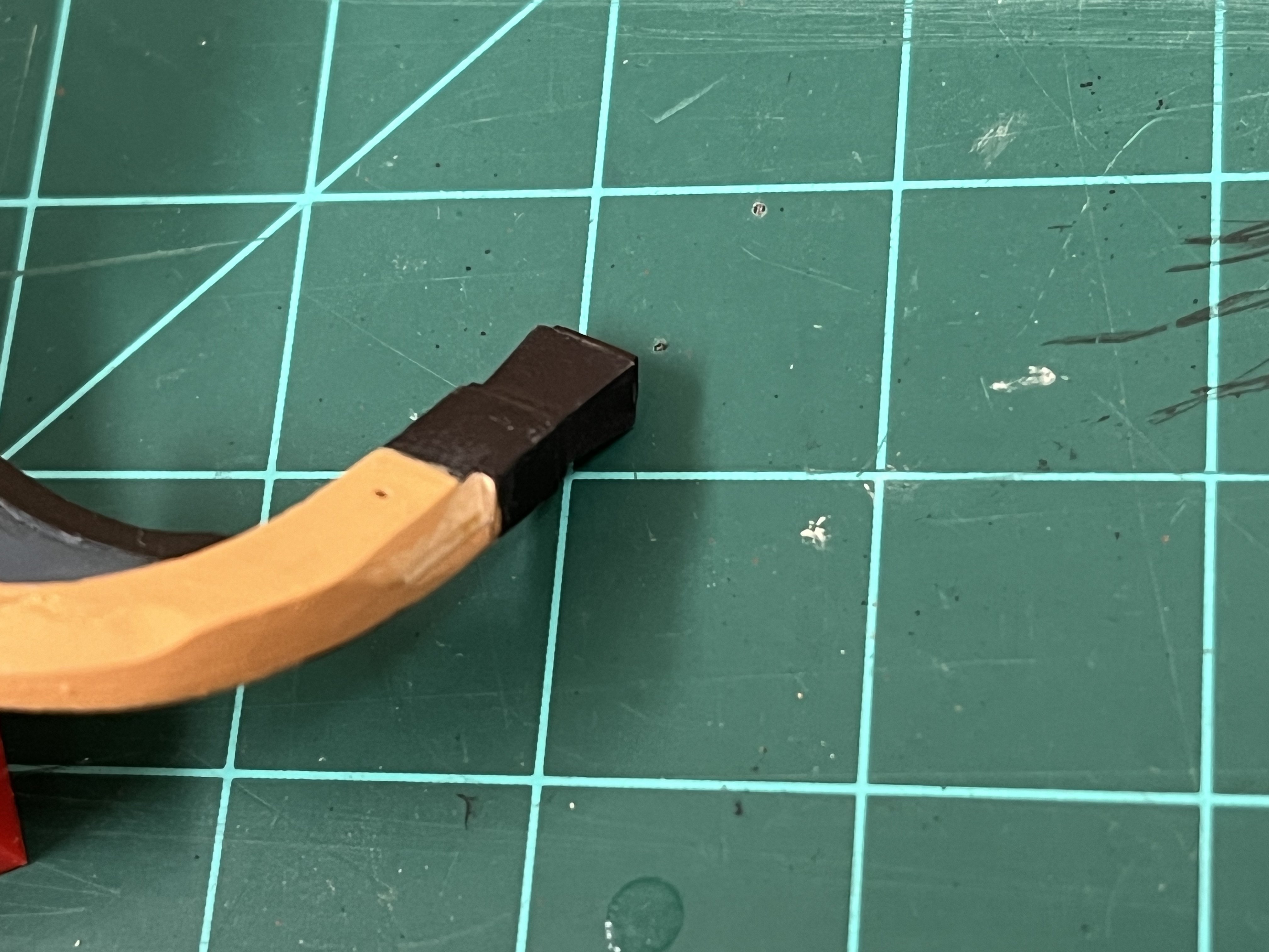
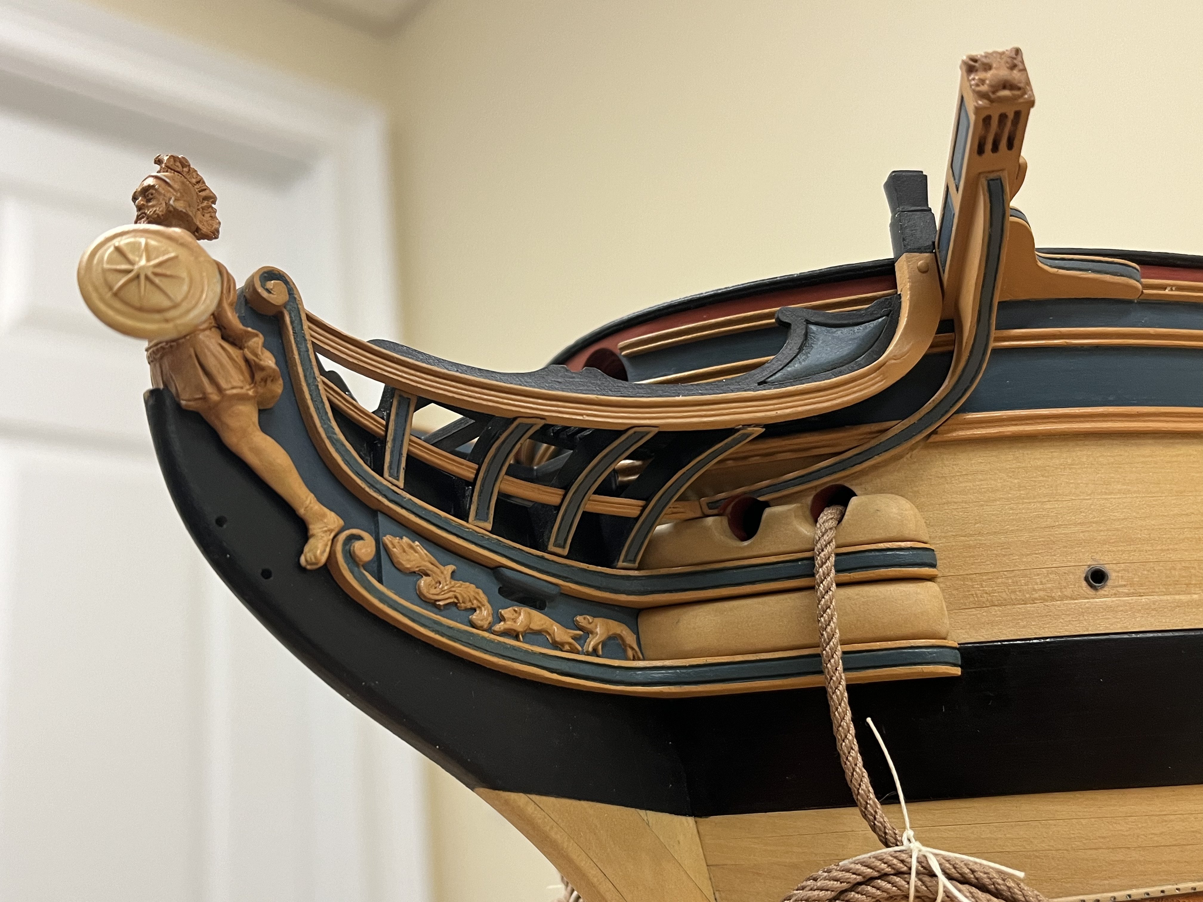
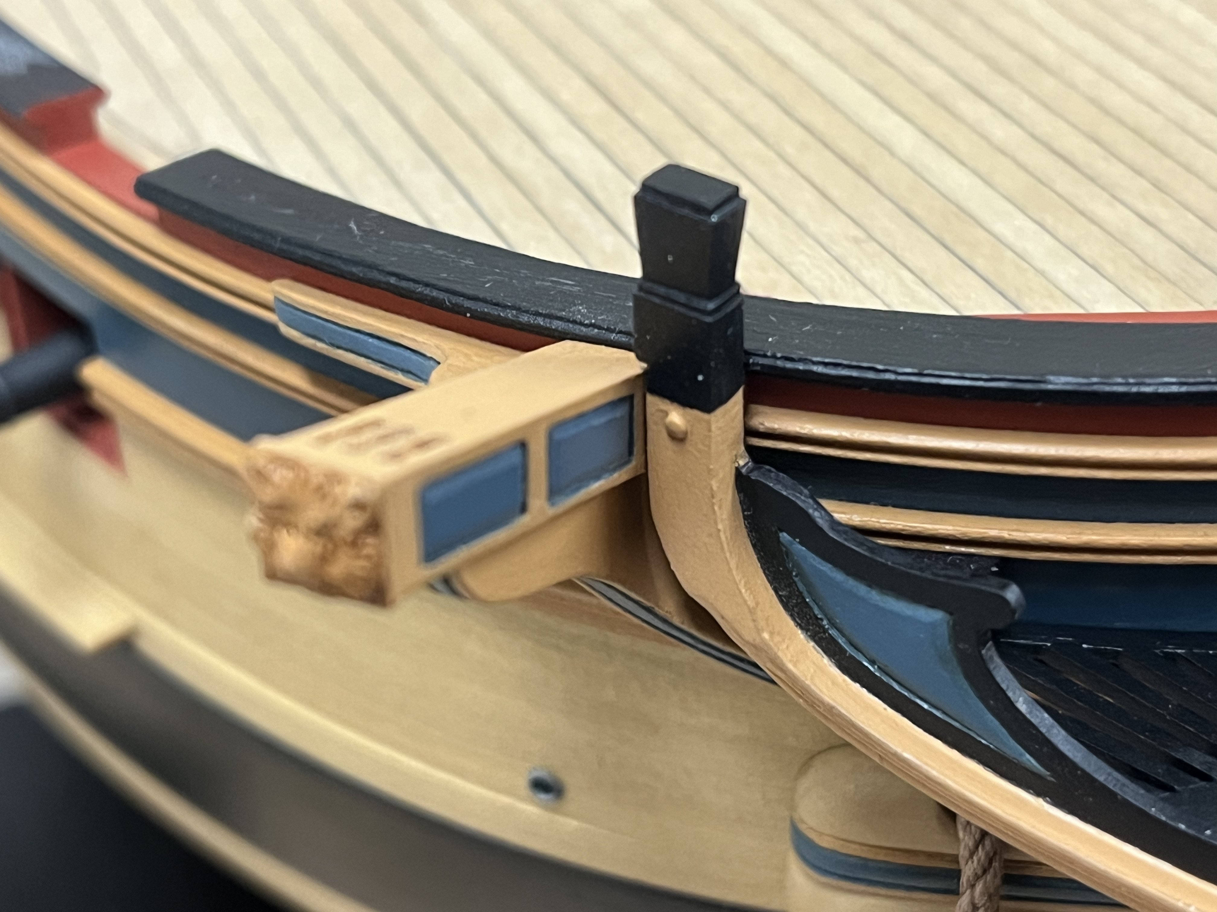
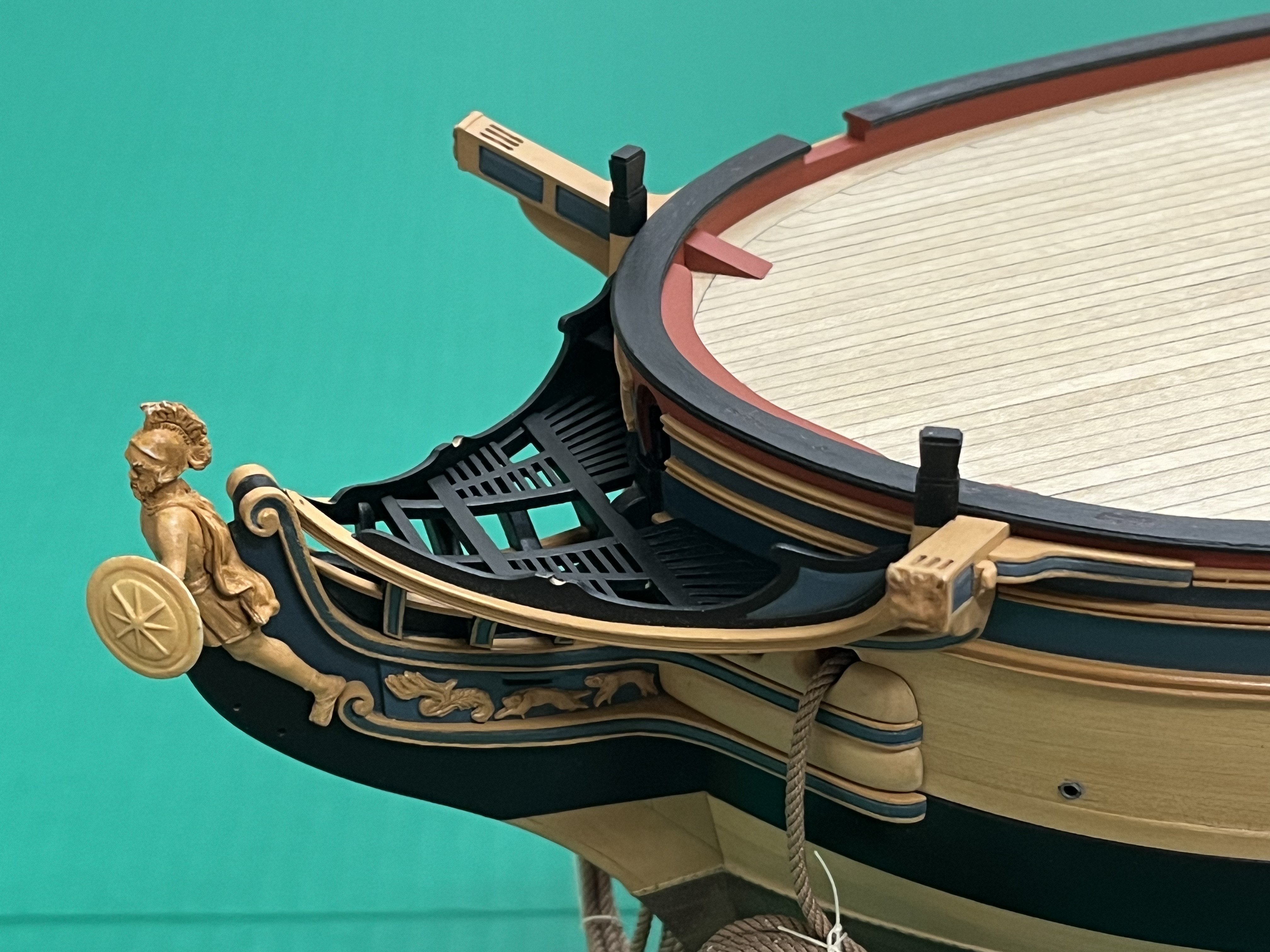
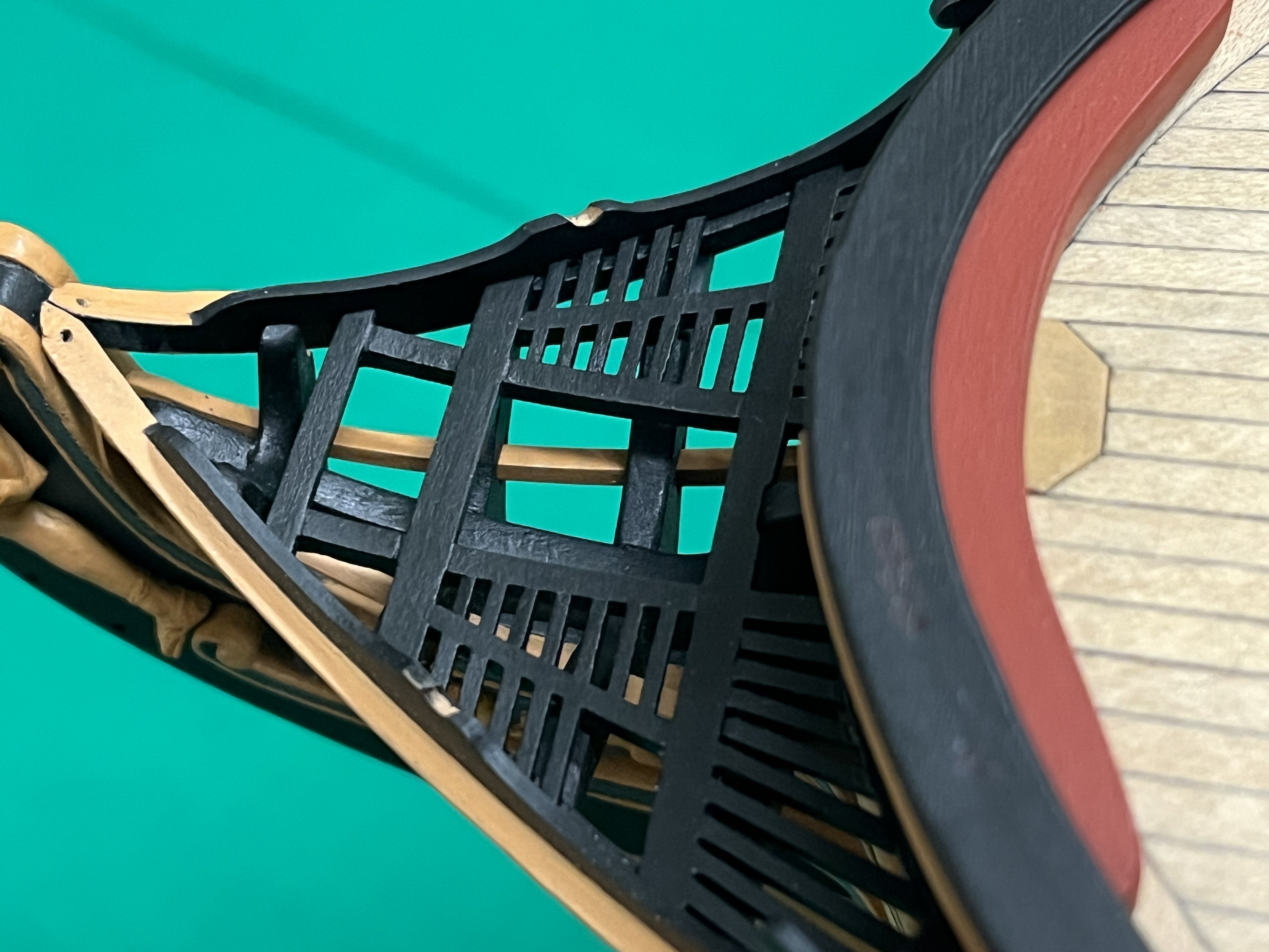
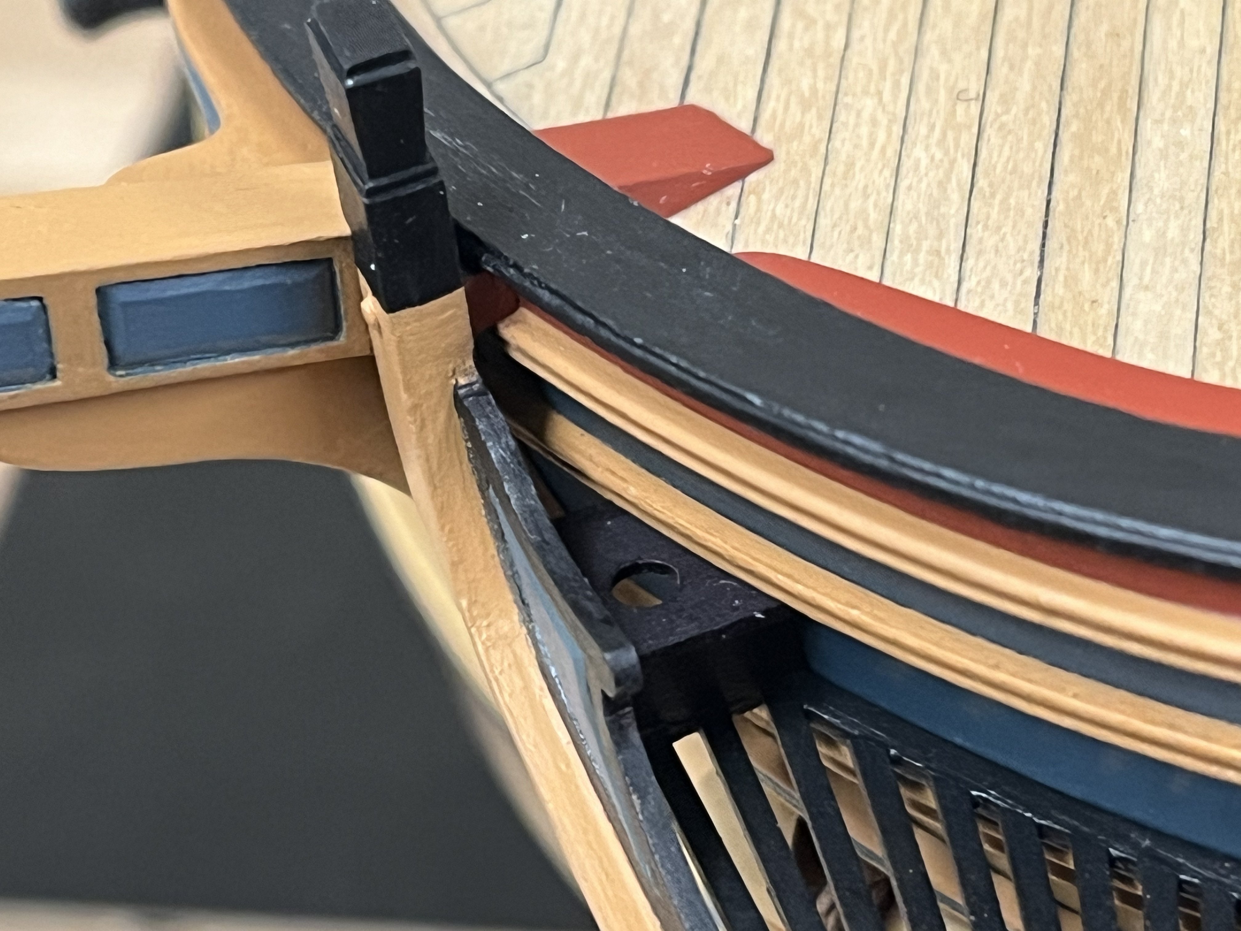
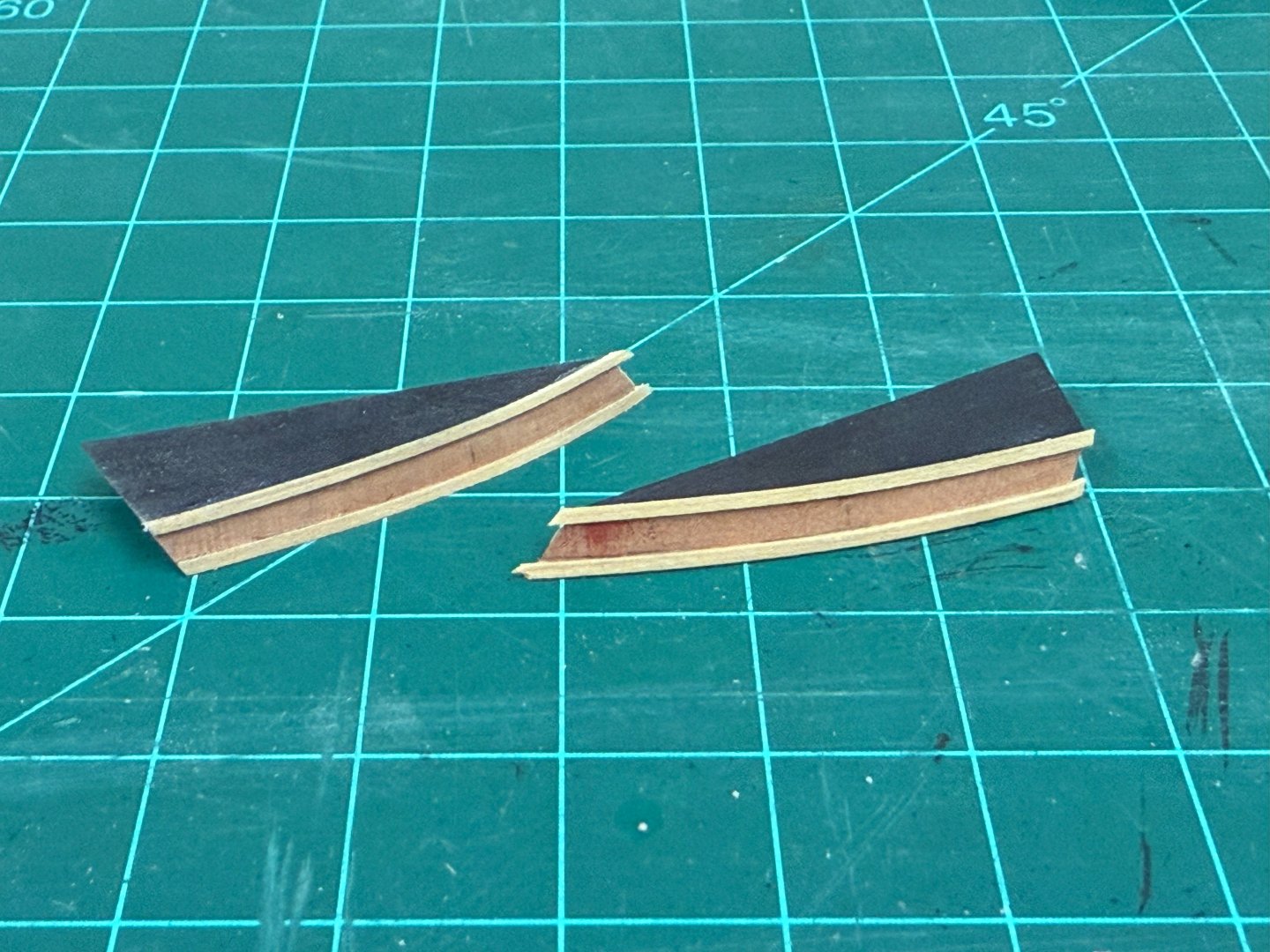
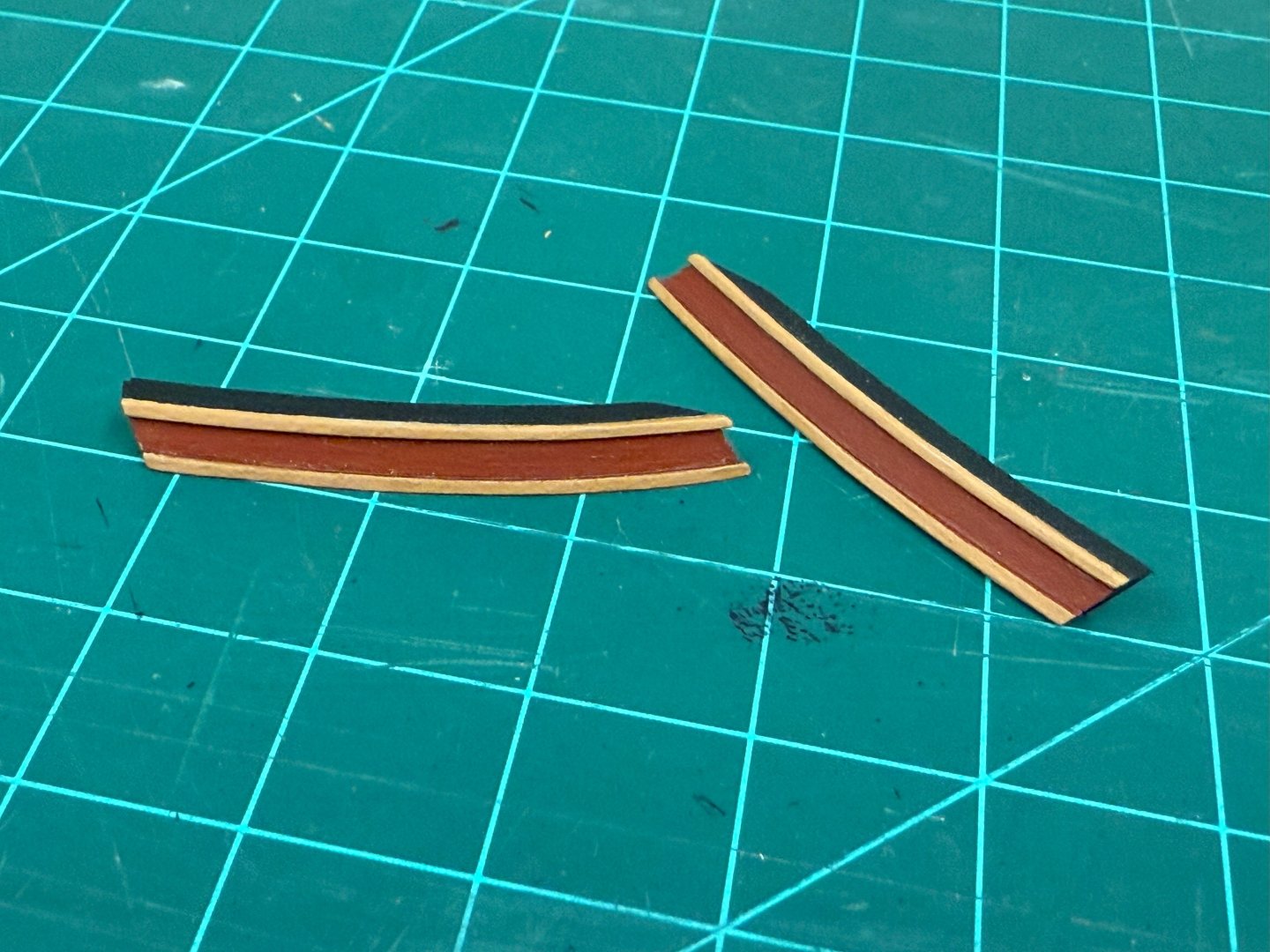
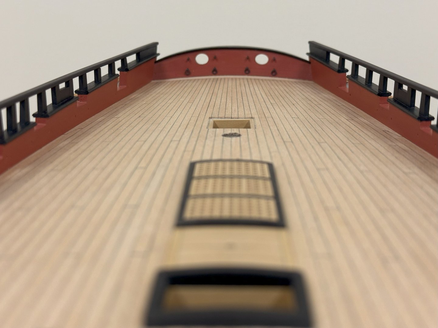
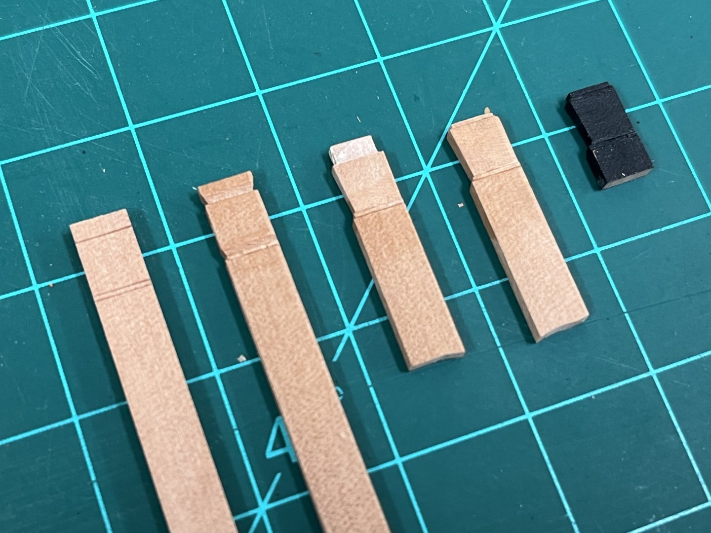
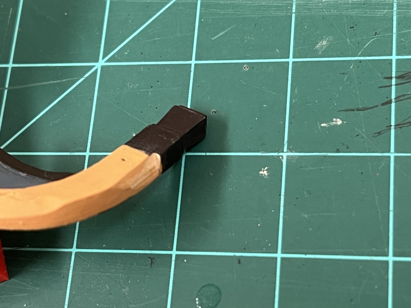
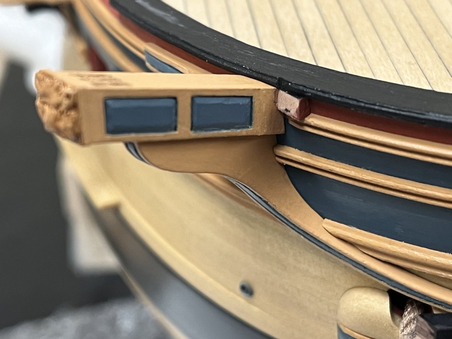
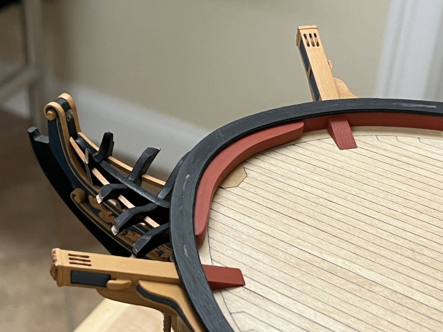
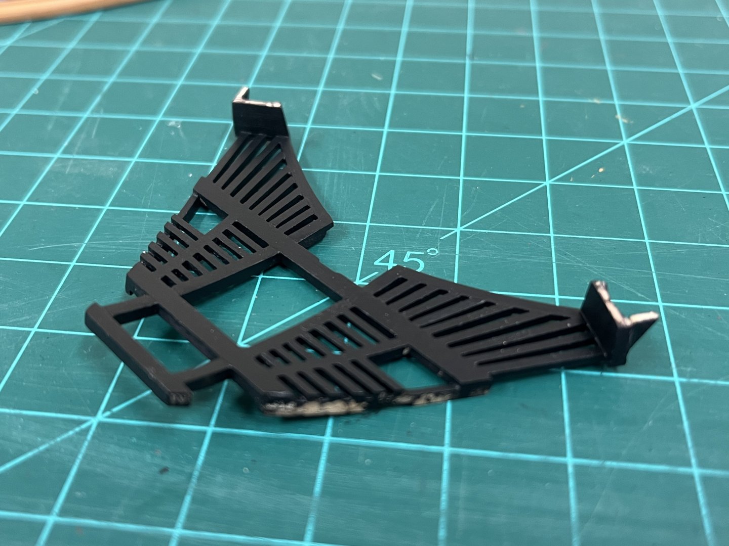
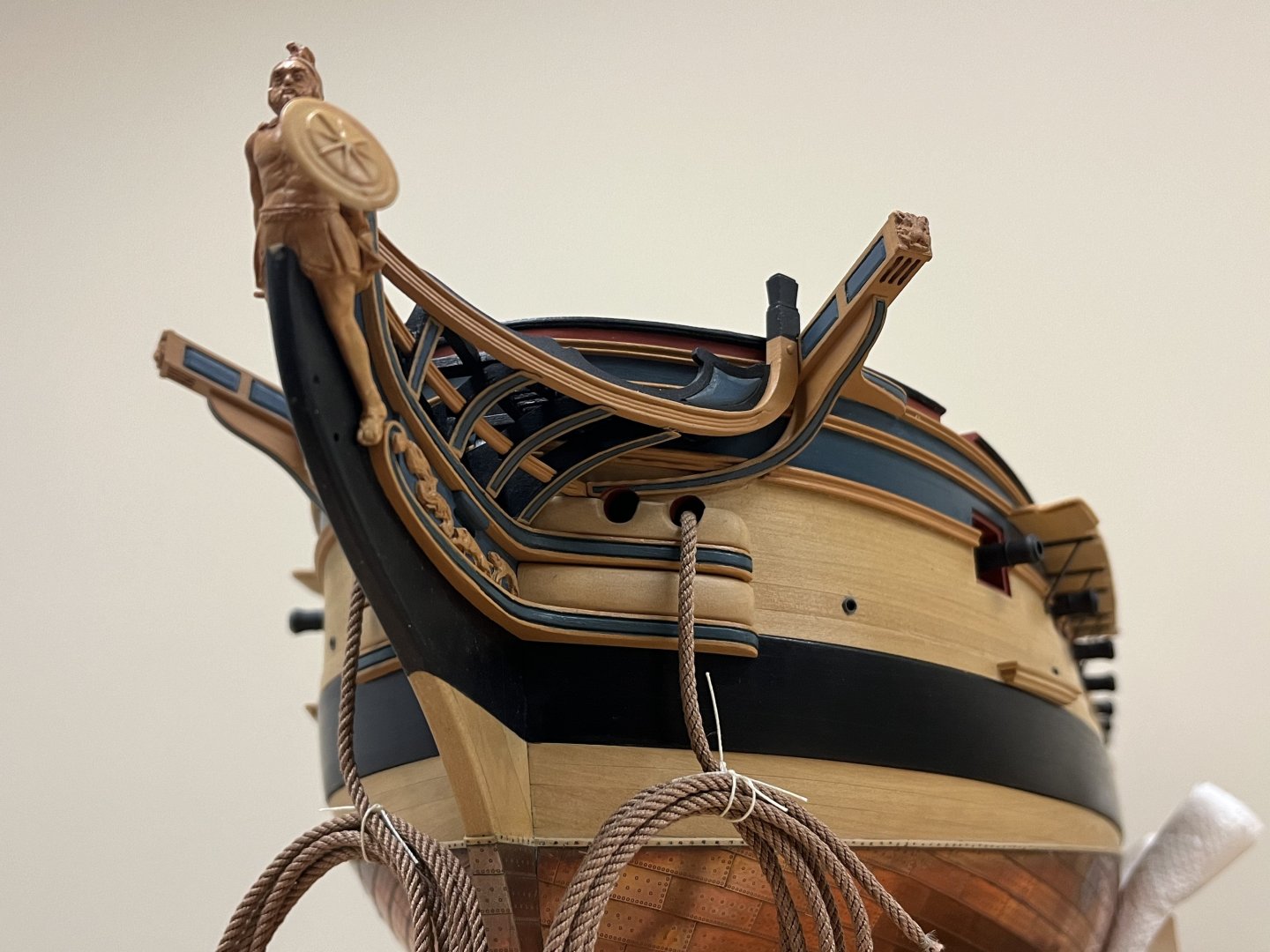
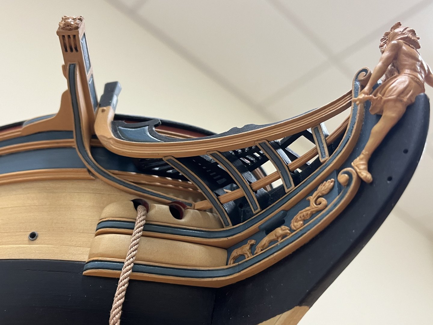
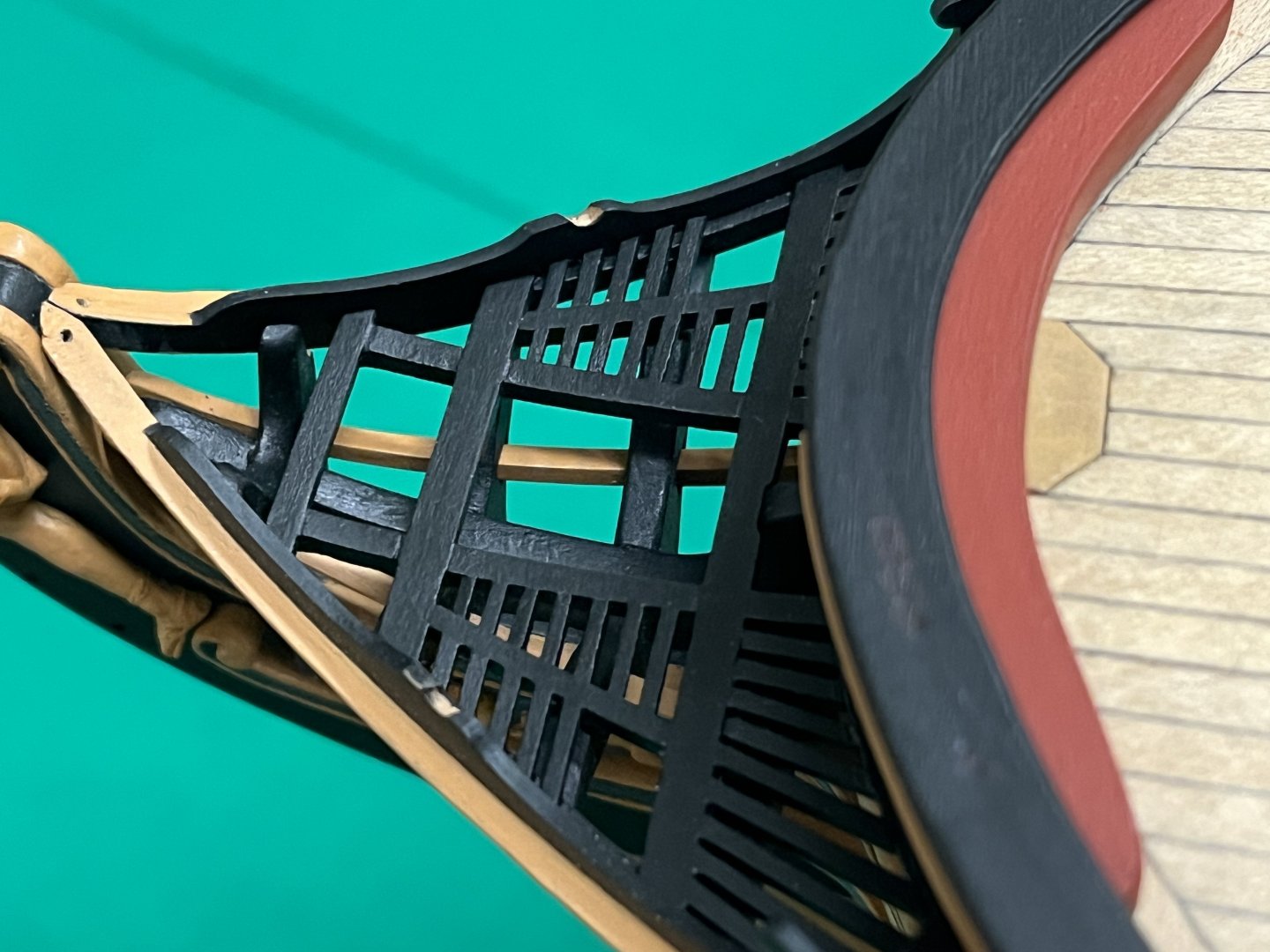
Its scary to note that my last update was 9 months ago, much has dragged me away from keeping current with other's builds on this wonderful site, and making progress myself. While not much, this brings me up to date. Head Grating: This caused much pondering! Like everything, this had to be scratch built. and wasn't quite sure whether I could pull of the gracefully curved gratings that grace many period models. In the end, this turned out to be a highly enjoyable little project. The main framing elements were built following the layout and dimensions of previously assembled components. The outside angled edge follows the curve of the main headrail, and the inside a foreshortened version. No real secret other than use of lots of templates and continual trial fitting. The larger framing elements were joined with a simple box joint for strength, the battens were individually shaped and glued end on. Once completed, the front of the seats of ease were attached to simplify final installation. Catheads, fo'c'sl plansheer and breasthook: With the gratings finalised, it was possible to install the catheads with some confidence. The breasthook was cut following dimension estimates from contemporary models (as much as possible) Prior to that however, the fo'c'sl plansheer was finalised, which required the underside where the catheads are located to be slightly angled to allow for the upward slope of the cathead given the overlap of the plansheer, and to ensure it sits flat. Timberheads: It was necessary t get my head around how I was going shape the timberheads, and figure out what was possible, so that I could both get some practice in shaping these and maximise the chance that these could be kept consistent and of an acceptable appearance. I did not want to have to redo the head rails as these had taken many hours to make. After some experimentation, the following approach seemed to provide the most consistent results for me. 2x5mm pear was used. From left to right: Preventer cuts were carefully made using a jig and #12 Exacto blade The edges were cut back gently to roughly preform the shape. I found the wood surface had a tendency to break off even with care so there were losses. Wipe on poly was applied at the cuts at this stage to both prove better visibility for further shaping, and also to harden the edges that had been formed The sloped faces were further refined, again carefully using a #12 Exacto blade, sanding sticks and microfiles. The top is deliberately made a little overlong as it makes shaping easier The top is reduced to final dimension... The overall height is reduced to final dimensions (in this case 10mm) Finalisation and installation of the main rail and grating: The main rail could now be finally dimension and shaped. As identified in TFFM, it did prove necessary to shape for rear outside profile to ensure it fits nicely to the cathead. I couldn't find much in the way of detail here, but the AOTS Diana book shows a slight wedge of wood sitting between the hull and the head rail. I decided to add two small wedges to ensure the headrail is fully secured to the hull. The plansheer also had to be nicked to allow it to sit properly. And with everything finally installed...I am greatly relieved and pleased with the way this has turned out as this proved to be a most challenging, but ultimately satisfying, adventure. The fore seats of ease have been made up and will ultimate slot into the grating, but these will not be installed until the placement of the boomkins is determined as everything is very tight in this small area.


-
Just in awe of what you have accomplished here with the 3D printing capabilities and out of the box thinking - your execution wonderful as well and the printed small parts so enhance the finished result. Very nicely done indeed!
-
Looking very good moonbug, coming together very nicely. Where did you find info on the 'swifter'?
- 419 replies
-
- 3
-
-
- Victory Models
- Pegasus
- (and 2 more)
-
Glad I've found your log sizzolo, you have made an outstanding start with some great details. Quick comment on the coppering, believe that the method was somewhat nation specific. US practice as you show was to have a parallel band at the waterline, RN practice was to copper from the keel upward. None of that takes away from the wonderful work you've done and would not be noticeable at this scale.
-
Hi David, when I first saw your log I was a little unclear on what you were looking to do, but I stand in awe of your efforts to fix this ugly duckling as she was. I have enough challenges putting up with my own mistakes and shortcomings to be able to deal with someone elses! Its commendable what you are looking to accomplish and I sincerely hope that you are able to enjoy the process and the ultimate results, will definitely be following along for future installments.
-
Been a long time since I've commented, but very much enjoyed catching up on your excellent work on this wonderful build. Love the colours you've chosen on the pinnace which are a pleasant change and gives a very period feel. I've just ordered this little kit myself from Chris, so hoping mine turns out half as well as yours. Great stuff!
- 648 replies
-
- 7
-
-

-
- Indefatigable
- Vanguard Models
- (and 1 more)
-
Looking very nice Dave, all the deck details coming together very nicely. Upper deck armament is definitely an ultra-marathon and not a sprint.
-
Hi David, so pleased to see you have completed her, unfortunately I've not been 'around' for a bit so missed the last steps in real time. Congratulations! You have created a truly spectacular model, and I have greatly enjoyed following your build from the start and learning with you, one of the great fellowship of Diana builders 🙂 I look forward to catching up with your future builds! All the best, Jason
- 310 replies
-
- 2
-
-
- Diana
- Caldercraft
- (and 1 more)
-
Your bowsprit came out very well indeed! Love the headshots and the bow detailing, really shows off the quality of your work and the period look you've achieved. I continue to eye your timber heads enviously, hoping I can get something close carving out of wood!
-
The boxwood is looking very nice Dave. Other than the visual benefit of the much nicer Amati plates, the other advantage is that you can lay rows of them as a single piece if you break them carefully from the sheet. Once glued in position, you would never know, and it can help keep the rows in line more easily....think its also quicker!