


Beef Wellington
-
Posts
2,249 -
Joined
-
Last visited
Content Type
Profiles
Forums
Gallery
Events
Everything posted by Beef Wellington
-
 Glad you've started a build log MM, this is a particularly intriguing kit. Look forward to seeing your progress.
 -
Jeff, I'm not familiar with Badger, but there are plenty of Badger logs on the site for you to reference which would likely be of value. The construction method you reference is pretty common to all Caldercraft (and other kits). You'll be surprised at the strength of the final hull once the second planking has been installed, and especially after the additional interior planking has been attached. Just be sure to get a good glue bond between the ply template and the limewood first planking edges. I have found that a SMALL amount of PVA glue on the bulkhead extensions can help ensure these stay positioned appropriately Personally, I've never found a use for the pins, but many people here seem to use them. BTW - welcome to MSW, and I'd strongly suggest starting a build log, photos are a big help to others to help you, and you will get plenty of good advice and support.
-
Wonderful detailing David, looks great. I do dislike the supplied funnel, 2lbs of poorly defined white metal, but you've managed to get it looking good.
-
Think it is also worth adding that there is not always an answer to all questions, even with AOTS books, NMM plans, models etc. There are often many small discrepancies and inconsistencies between even contemporary sources (especially the Artois's!), but part of fun is learning from this and working through these challenges to find the direction you want to go in. Look forward to seeing you start.
-
What a wonderful model Derek, only just caught up on your progress. Aside from the excellent execution, the tones of the boxwood sit very nicely with the eye.
- 345 replies
-
- 1
-

-
- Duchess Of Kingston
- Vanguard Models
- (and 1 more)
-
Beautiful pictures Peter, you've done an amazing job on the hull and the sails and running rigging look fantastic. The detail in the deck shots really show your workmanship.
- 366 replies
-
- 4
-
-
- bellerophon
- victory models
- (and 2 more)
-
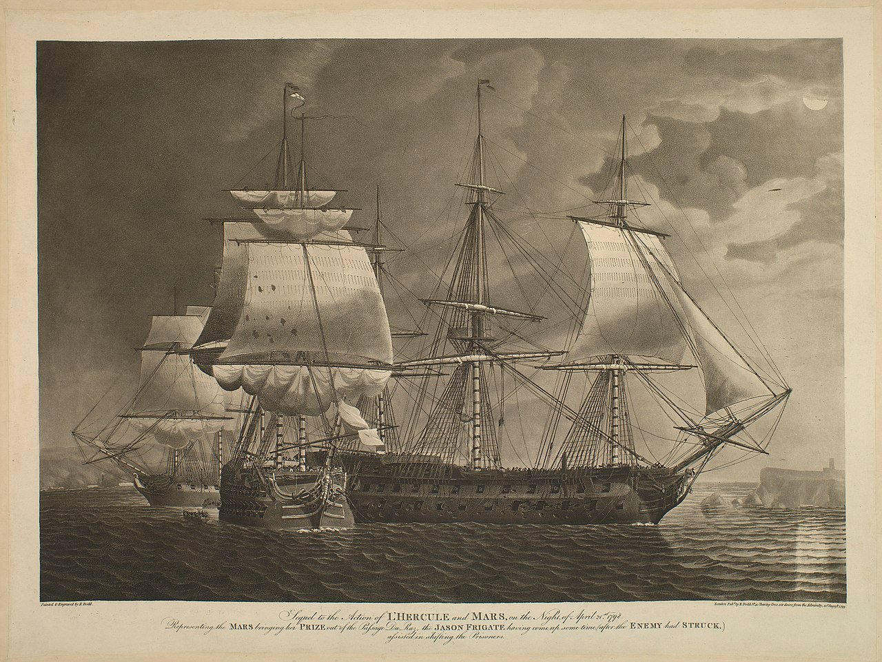
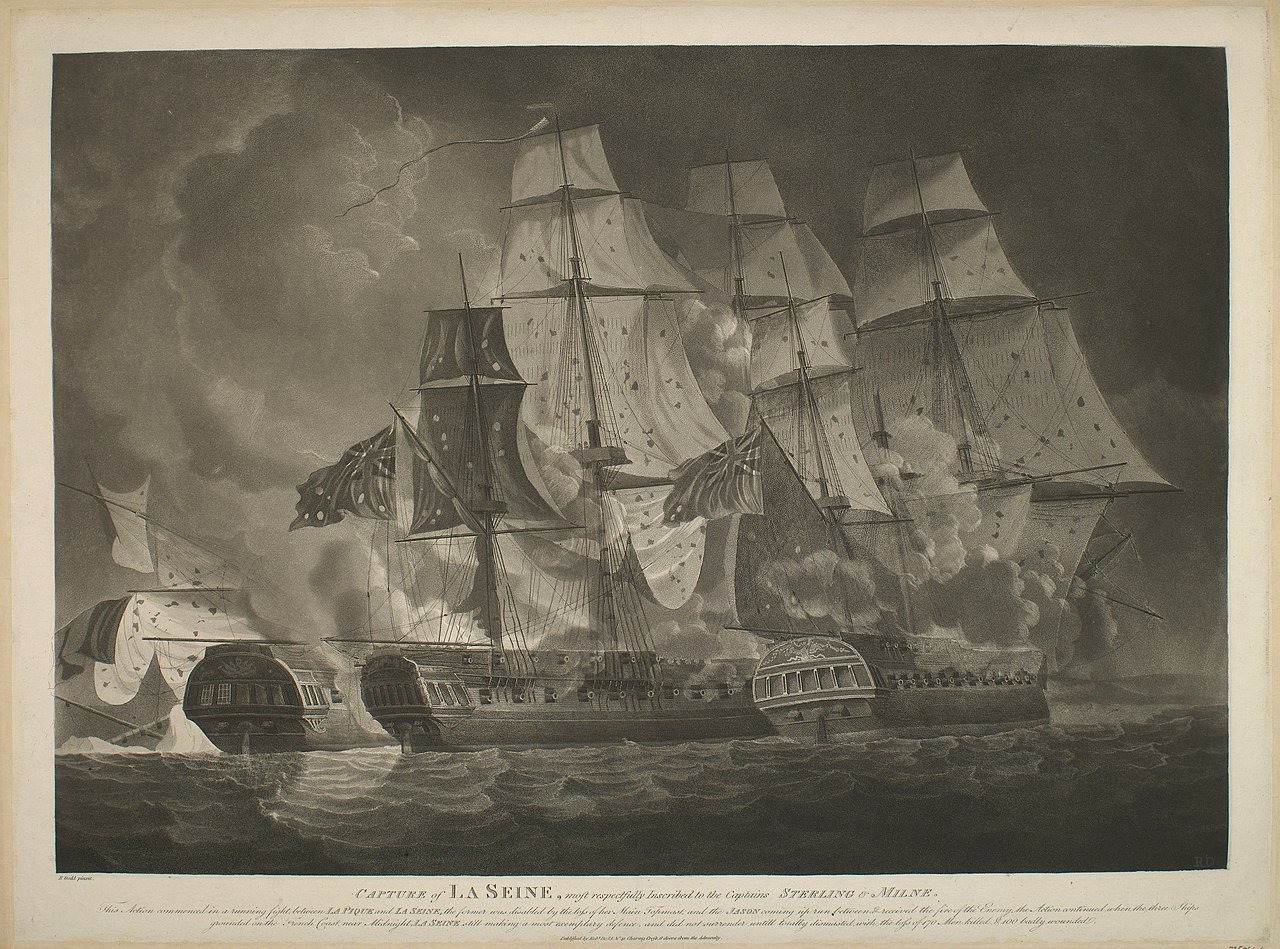
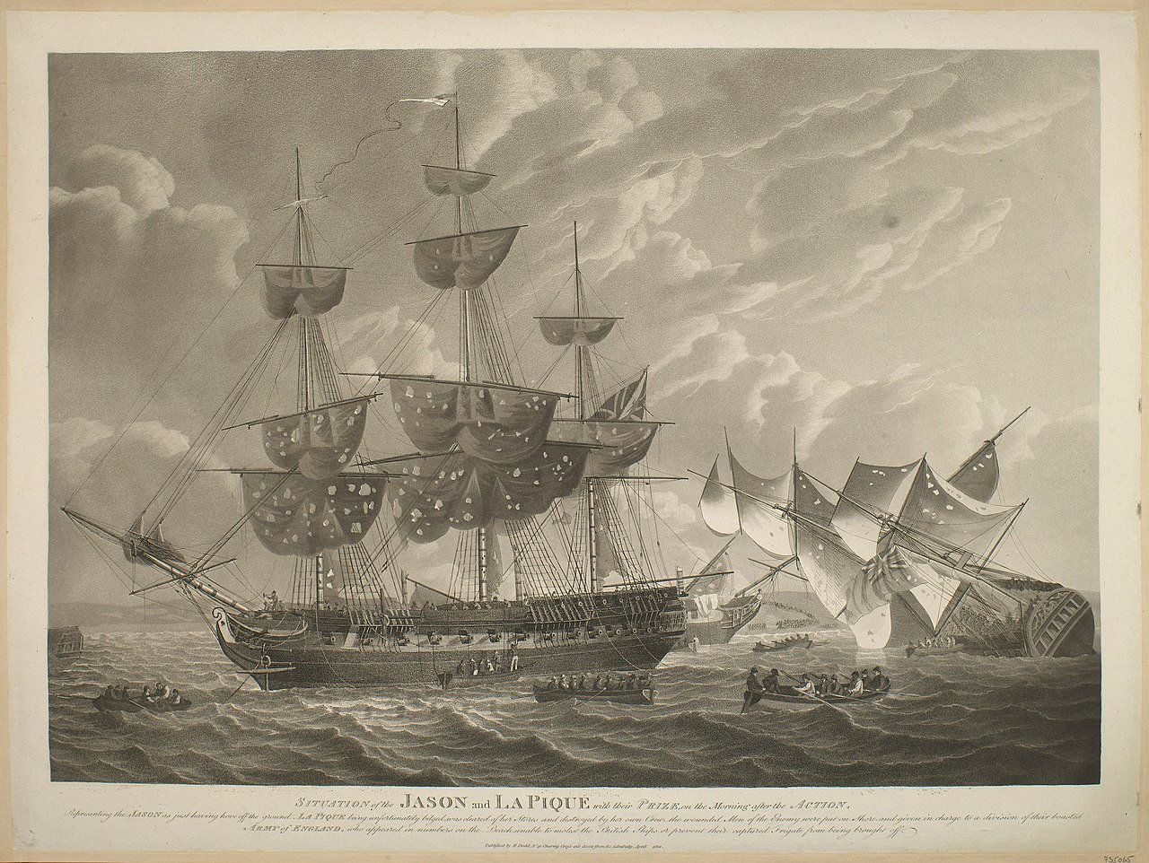
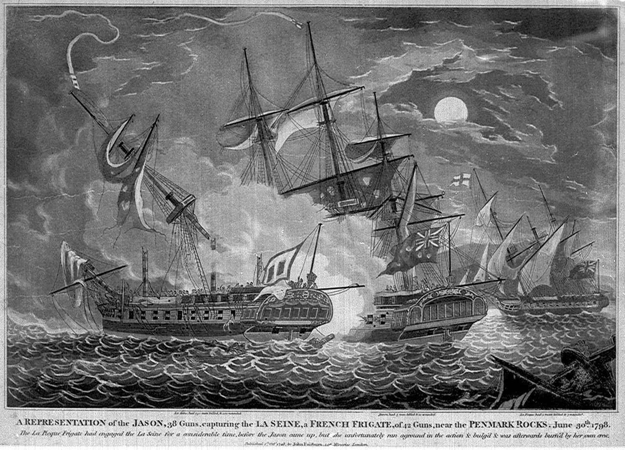
Work continues slowly, but not really anything that would be noticeable in a photo update. In a shameless attempt to cover this up, sharing some contemporary print images that I've been trying to get my hands on for quite some time now. (The 3rd print below first appeared in my second post in this log back in 2014...ahem...I'm including here for completeness). Three of the four are by Robert Dodd, and the other is by John Fairburn, and correlating with NMM records, were contemporaneously created between 1798 and 1801. Its hard to corroborate the details between artists because the Robert Dodd prints are of a much higher quality - a comment on Dodd reflects that he is likely a reasonably reliable source "Although technically accurate and meticulous, his artistic talents were somewhat eclipsed by the greatest of his peers, and it is his contribution to the historical record that is his greatest legacy". Considering that the representations were 'inscribed to' the ship's captains, one might think that they would be accurate on key points. Full details below, but a couple of things jump out, nothing here will change the approach being taken on this build, but may be of value to others. I'm really hoping I can get my hands on building contracts now. Shock and horror! - there 'aint a figurehead! Jason is clearly shown with a fiddlehead stem! - this is contradictory to available plans and seems unlikely to be an artistic creation. Especially as other ships represented show quite detailed figureheads. Jason is shown with 14 quarterdeck 'guns' - impossible to tell whether these are carronades or cannons. In any event, these exceeds the number described in AOTS Diana and seems to exceed Admiralty regulations. Perhaps Capt. Sterling pulled in some favours to obtain additional ordinance...It's hard to draw any conclusions on the bow armament because its just not clear enough. The Mizzen channel is also clearly shown at its original lower location together with a backstay stool (4th picture below). This reflects the earlier (original as designed/built?) configuration, and contradicts the single channel configuration located higher up the hull that is shown in AOTS and (possible subsequent alterations) on NMM plans. Interestingly, the same configuration is shown in second picture below, but the mizzen backstay stool is missing. Try as I might, I just can't resolve much in the way of clues to the stern decoration. Maybe wishful thinking, but the central figure on the stern in second picture below could be a golden fleece (as would possibly be expected!), and what I'm noodling over for 'my' Jason. The outboard supporting figures also look 'male' to my eye...but not sure. There are a number of details here that suggest a different representation here (e.g. ar those columns between the lights?). Wish I'd managed to get my hands on this years ago. Unfortunately, the representation by John Fairburn is of much lower artistic and technical and just seems to show smudges. Sequel to the action between L'Hercule and Mars (April 21, 1798): Artist: Robert Dodd ca.1798 Inscription “Sequel to the Action of L’HERCULE and MARS, on the Night of April 24th 1798. Representing the MARS bringing her PRIZE out of the Passage Du Raz, the JASON FRIGATE having come up some time after the ENEMY had STRUCK, assisting in shifting the Prisoners.” Capture of La Seine: Artist: Robert Dodd Inscription “CAPTURE of LA SEINE most respectfully Inscribed to the Captains STERLING & MILNE. This Action commenced in a running fight between LA PIQUE and LA SEINE the former was disabled by the loss of her Main Topmast and the JASON coming up between & received the fire of the Enemy Her Action continued when the [unreadable] Ships grounded on the French Coast near Midnight LA SEINE still making a most exemplary defense, and did not surrender until totally dismasted with the loss of 170 Men killed & 100 badly wounded” A REPRESENTATION of the JASON 38 guns capturing LA SEINE: Artist: John Fairburn, 1 Oct 1798 Inscription “A REPRESENTATION of the JASON 38 guns capturing LA SEINE, a FRENCH FRIGATE of 42 Guns near PENMARK ROCK, June 30th 1798 The La Pique Frigate had engaged the La Seine for a considerable time, before the Jason came up, but did unfortunately run aground in the action & bilged & was afterwards burn'd by her own crew" Situation of Jason and La Pique the morning after the engagement: Artist: Robert Dodd Description taken from NMM: A depiction of the British frigates Jason and La Pique on moderate seas, flying the British ensign, with their prize, La Seine, on 29 June 1798; troops can be seen on land in the distance. The Jason is shown in the foreground in port-broadside view, behind her is La Seine with her masts cut off; La Pique (port quarter view) is on the right in the process of sinking, shown with her crew climbing down on to a rowing boat. Several other rowing boats can be seen in the foreground. The sails of the Jason and La Pique show extensive damage from cannon fire. Inscription “SITUATION of the JASON and LA PIQUE with their Prize on the Morning after the Action. Representing the Jason as just having hove off the ground. La Pique being unfortunately bilged was cleared of her Stores and destroyed by her own Crew, the wounded Men of the Enemy were put on Shore and given in charge to a division of their [unreadable] ARMY of ENGLAND who appeared in numbers on the Beach unable to molest(?) the British Ships or prevent their captured Frigate from being brought off.”
-
As has been said, a 1:64 seventy-four is huge market gap....and so many great subjects. And of course the historic Leda class with 2 living examples...
-
Nice update David, sharing the challenges of the plansheer myself so appreciate the struggles. Your timberheads turned out very nicely indeed with some very crisp detail, ingenious to use 3D printed jigs. I will undoubtedly be going down the freehand road, but hoping it will be viable to make some less engineered jigs to get the angling correct. The headshots show shes coming together very nicely indeed, well done.
-
I would suggest using think back card or tape as you suggest. Think you will get a much better result that you ae happy with.
-
I too will follow along if I may, off to a nice start. This kit definitely has my interest piqued for the future. Are you going to build the split hull option?
-
Well done indeed with rounding that 1mm square stock, are you going to try and curve the blade? Big improvement on the kit offering.
- 106 replies
-
- 1
-
-
- Admirals Barge
- Vanguard Models
- (and 1 more)
-
Chris - for some reason I'm not seeing the photo (?). BTW, I like your confessional, you are now absolved 🙂
- 69 replies
-
- 5
-
-
- fly
- victory models
- (and 2 more)
-
Did you consider painting the details onto the bulkhead rather than using the stickers? Might be worth a try with nothing to lose and could give a much more pleasing result, I suspect that these should really be yellow ochre rather than black, with some light/dark highlights to give some depth.
-
Very nice build you have going on here Andrew, looking forward to seeing some more progress and will follow along.
-
Looking very good Stergios, you're getting really close now to finishing her.
- 1,144 replies
-
- 2
-
-

-
- snake
- caldercraft
- (and 1 more)
-
This model seems to sum up the concept of "less is more". You've done a fantastic job of her, the painting and weathering is very convincing.
- 65 replies
-
- 4
-
-
- X Craft
- I Love Kit
- (and 2 more)
-
This looks fantastic Chuck, what is your trick for removing laser char so thoroughly? Everything is so clean.
-
Glad you are 'happier' B.E., well justified in my humble opinion. Your tweaks have made all the difference.
- 106 replies
-
- 3
-
-
- Admirals Barge
- Vanguard Models
- (and 1 more)
-
You can view many models on the NMM site which I would definitely recommend. Books are an investment, but some I have invested in are the Rogers Collection Volumes 1&2 and 'The Sailing Frigate' by Gardiner, and 'The Ship of the Line' by Lavery. Both of the latter titles walk you through chronologically the evolution of ships interpreted through existing models. Absorbing all of the wonderful images of original models is something I will never tire of. It quickky becomes clear that there are many variations as has been pointed out. It is also clear that models do not always represent what is probably actual practice on ships - this leads to the first question to think through which is do you want to build a 'model of a model', or a model of the ship as it likely existed - there is bountiful evidence of the former, but not the latter. There are many examples, some of the most noteworthy being that models often appear highly decorated with friezes on blue backgrounds - likely not practical on a real ship, but very appealing to model makers when it seemed to be in fashion. The other consideration would be availability of paint colours - during the period in question, many colours existed but would have proved prohibitively expensive to all but the richest captains - so its most likely that red and yellow ochre predominated given its availability and low(er) cost. This does seem to be reflected on most contemporary models, which do not typically show multi-coloured stern decorations (or gold which seems to be some people's preference). Moving into early 19th century, white and green paint became more fashionable, and affordable and these started to replace the 'ochres'. These, and many more considerations suggest, as has been pointed out above, that there is not really a 'correct' answer, the best you are likely to achieve is 'directionally correct' 🙂 For what its worth, I am shamelessly taking the 'model of a model' approach for 'Jason', it is highly unlikely that any of the Artois class would have been so beautifully decorated. Indeed the only print I can find of 'Jason' shows her with the ubiquitous black hull with a stripe between gunports.
-
Congratulations Mike, you should be very proud of the excellent result!
- 109 replies
-
- 2
-
-
- snake
- caldercraft
- (and 1 more)
-
Where did you obtain the seated figures B.E.? They seem perfect for scale and dimension validation of the thwarts.
- 106 replies
-
- 2
-
-
-
- Admirals Barge
- Vanguard Models
- (and 1 more)
-
Thats a very nice treatise on rigging Mike! I think your efforts to show this for future Snake builders will be very valuable. Shes looking fantastic, very well done.
- 109 replies
-
- 2
-
-
- snake
- caldercraft
- (and 1 more)
-
Looking forward to your next update Mark...taps fingers 🙂