Beef Wellington
-
Posts
2,249 -
Joined
-
Last visited
Content Type
Profiles
Forums
Gallery
Events
Everything posted by Beef Wellington
-
 Well done Alistair, I also have these beauties in waiting and you've set a very high bar. Love the wick, just out of interest what did you use? Your thought on the wire support seems a good one.
 -
Ah-ha, been hunting high and low for you....and finally found you! This looks like a very nice kit, and a pleasant change to the usual. Looking forward to seeing more progress, looks like you're off to a great start.
-
I think you'll find that gallery former is very oversized. Suggest determining the right size and then playing around with the various items to get the best compromize. I never used this part. There are going to be compromises needed between the plans, AOTS and even the original plans because none of them reconcile exactly. Playing with the PE quarter gallery lights may also help you get a better sense of the final visual proportions. Good luck!
-
Looking very nice David, think all these small details, although somewhat obscured, make for a much more satisfying result.
-
Thats fantastic work Mark, beautiful joinery! I love seeing the detail of your approach to these complex pieces.
-
Looking very nice Dave! I think your decision to hold off on cutting the upper cannon/carronade ports is a sound one, these are no harder to do at a later date and as you indicate, you will have more data points to make a good decision. As I'm sure you've read, the placement of the stern fascia is difficult and can result in frustration down the road. The advice I would give would be to determine the position of the quarter galleries first (the bottom of the quarter gallery lights are at exactly the same height above the main deck as the lower edge of the gunports). This then will allow you to position the stern fascia with confidence as the sweep of the lower edge of the stern lights meets up with the lower edge of the quarter gallery lights. (You will need to account for the additional distance to the outside of the quarter gallery here). Adjustments to the lines of the upper and lower counter to match are more easily done at this point.
-
It seems very odd that the jib-boom would be secured without a rope lashing, and I suspect it is an omission in the AOTS.
-
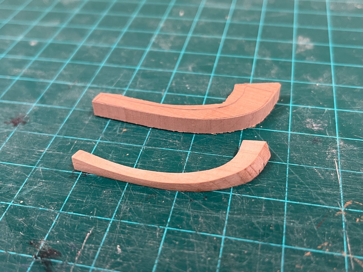
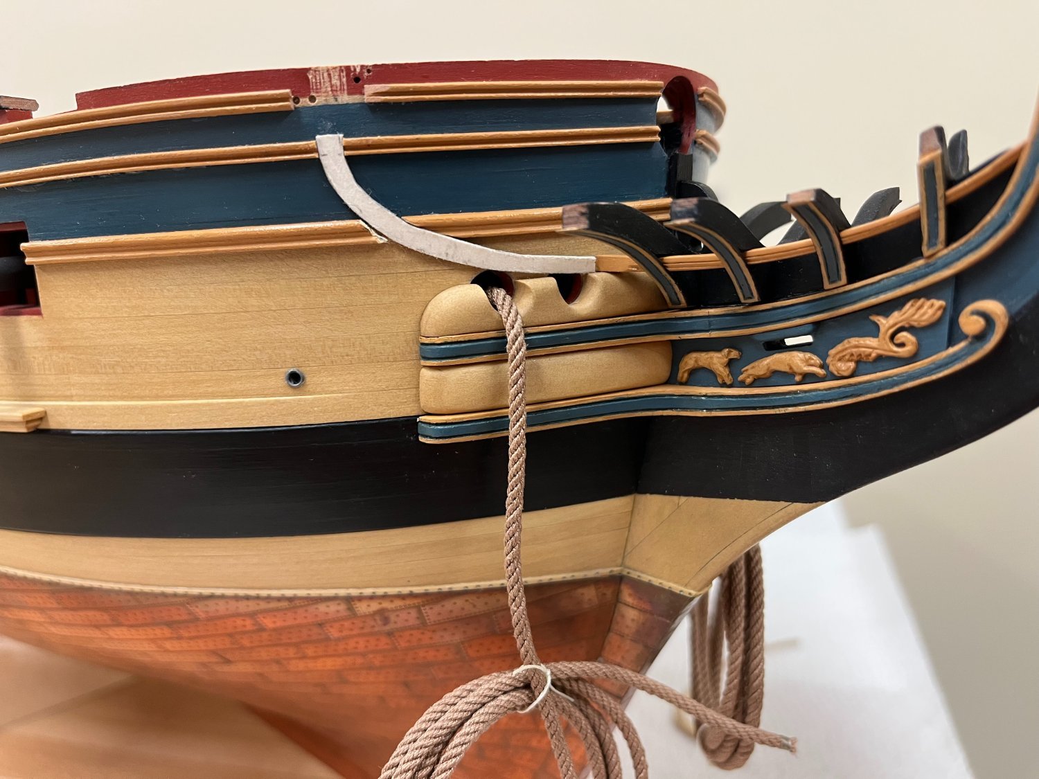
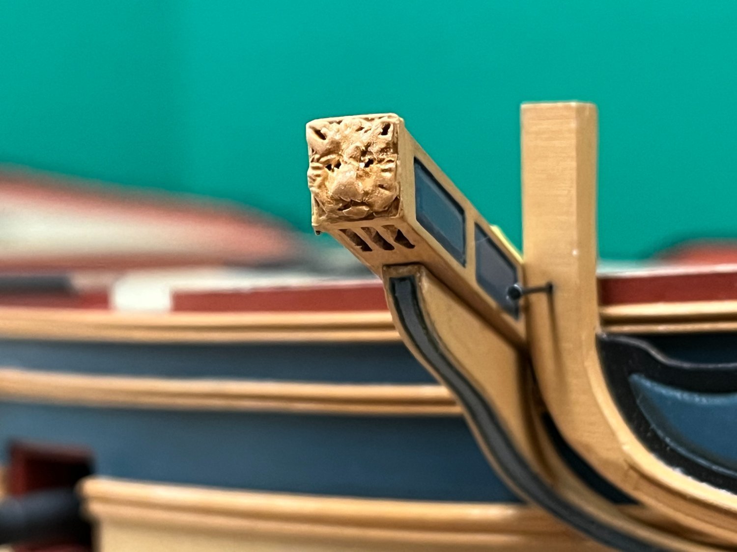
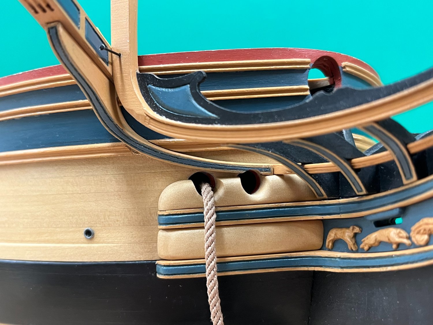
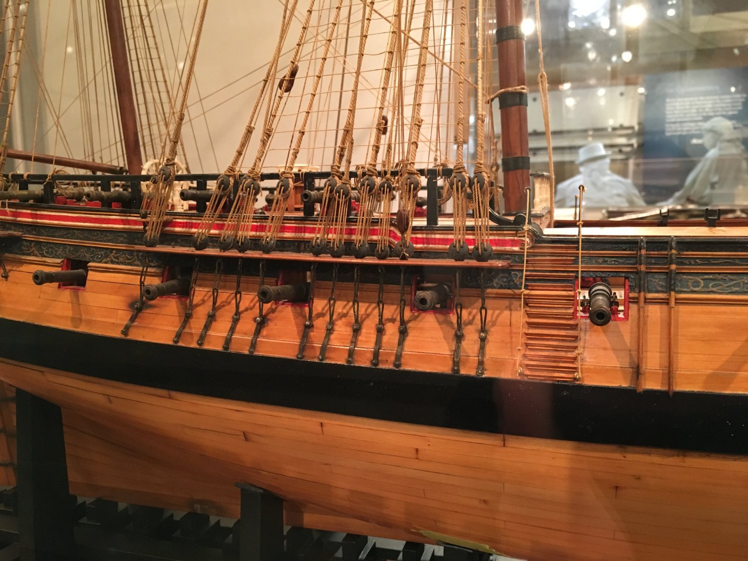
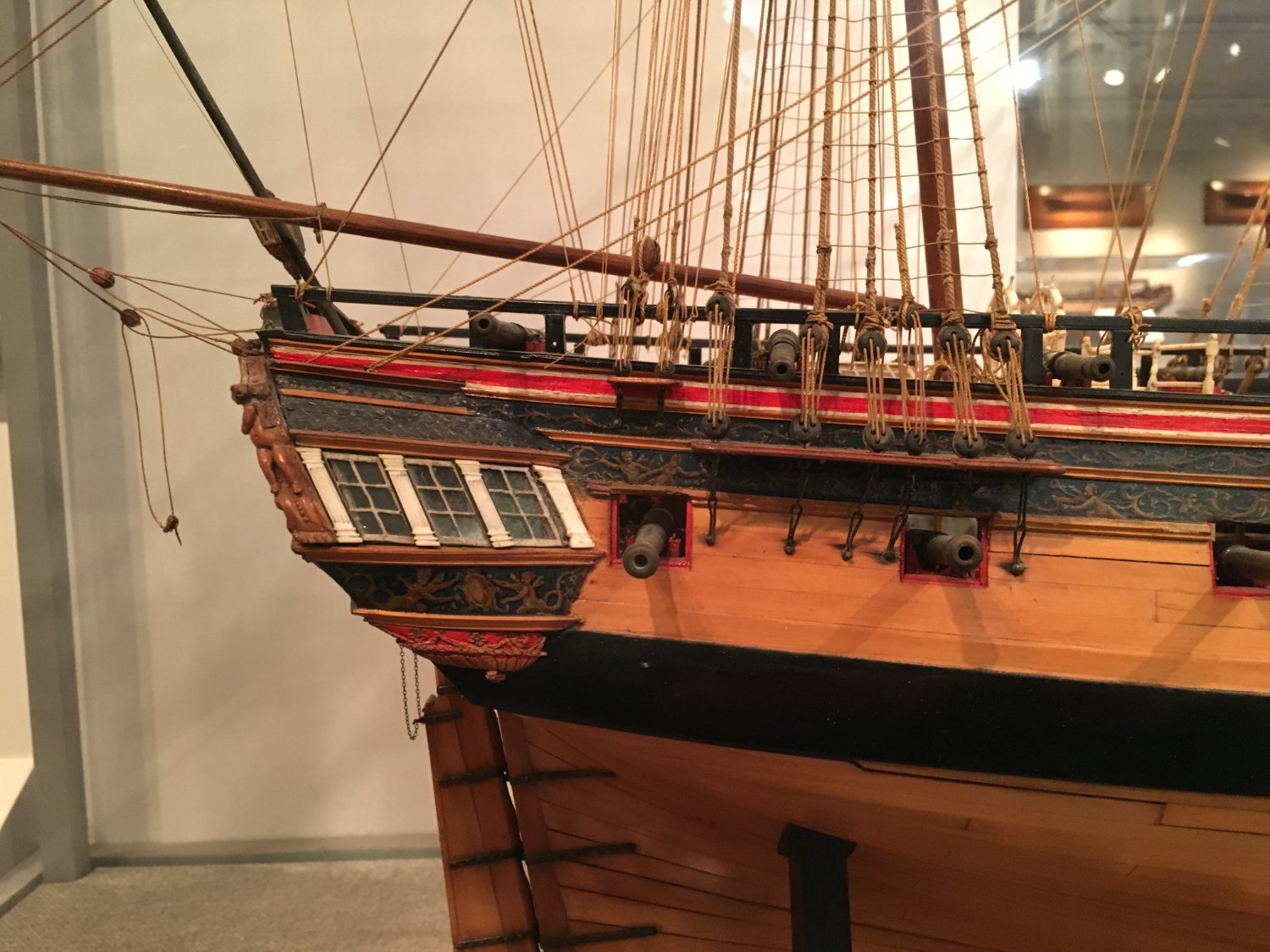
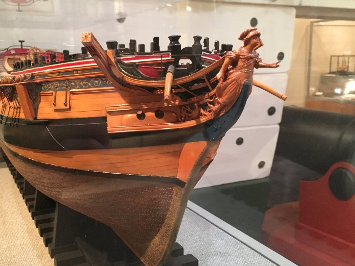
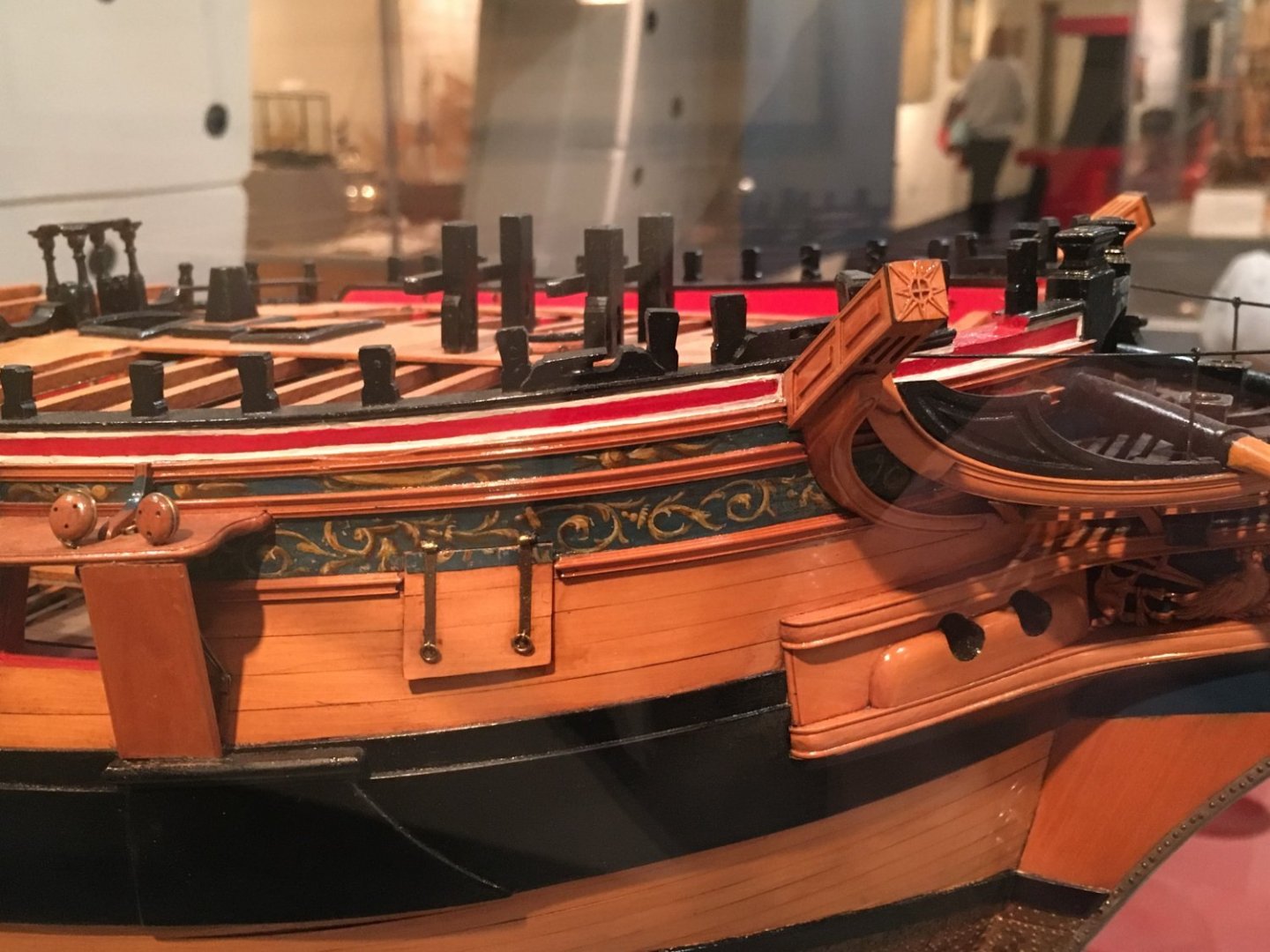
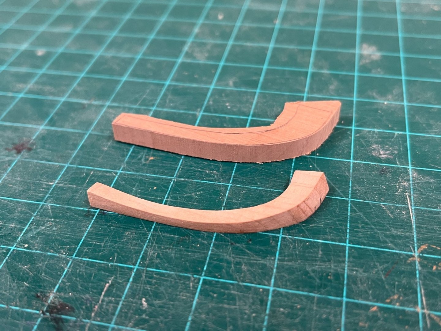
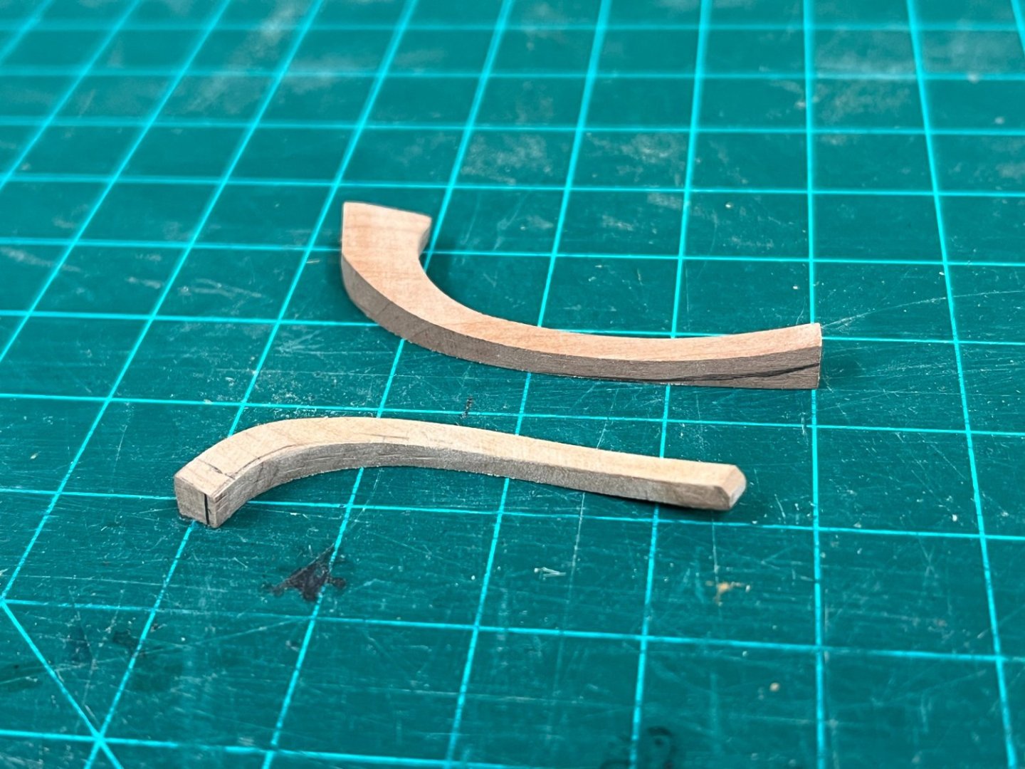
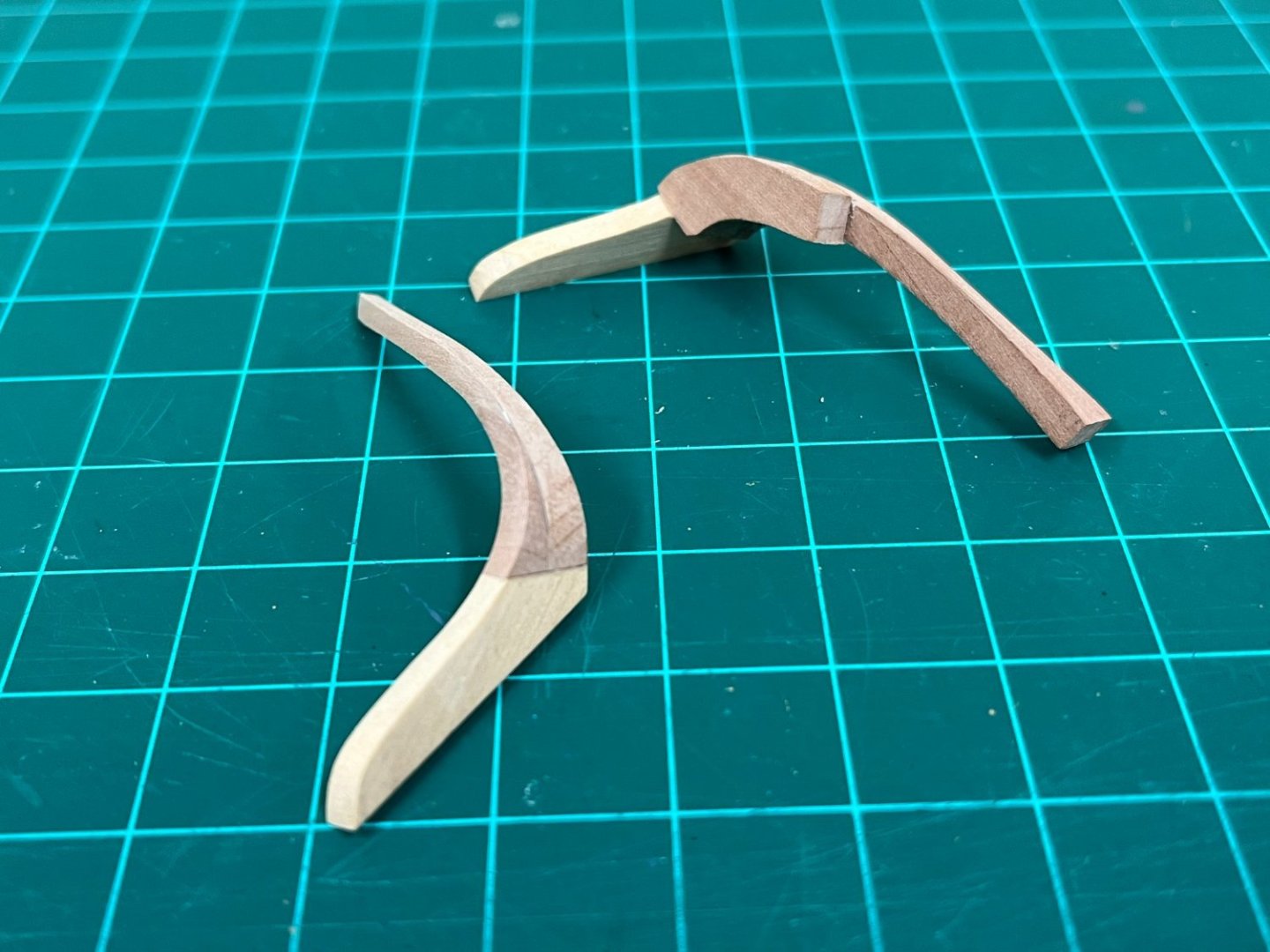
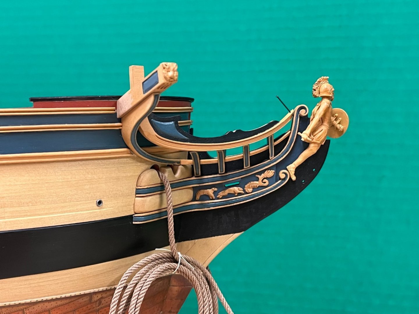
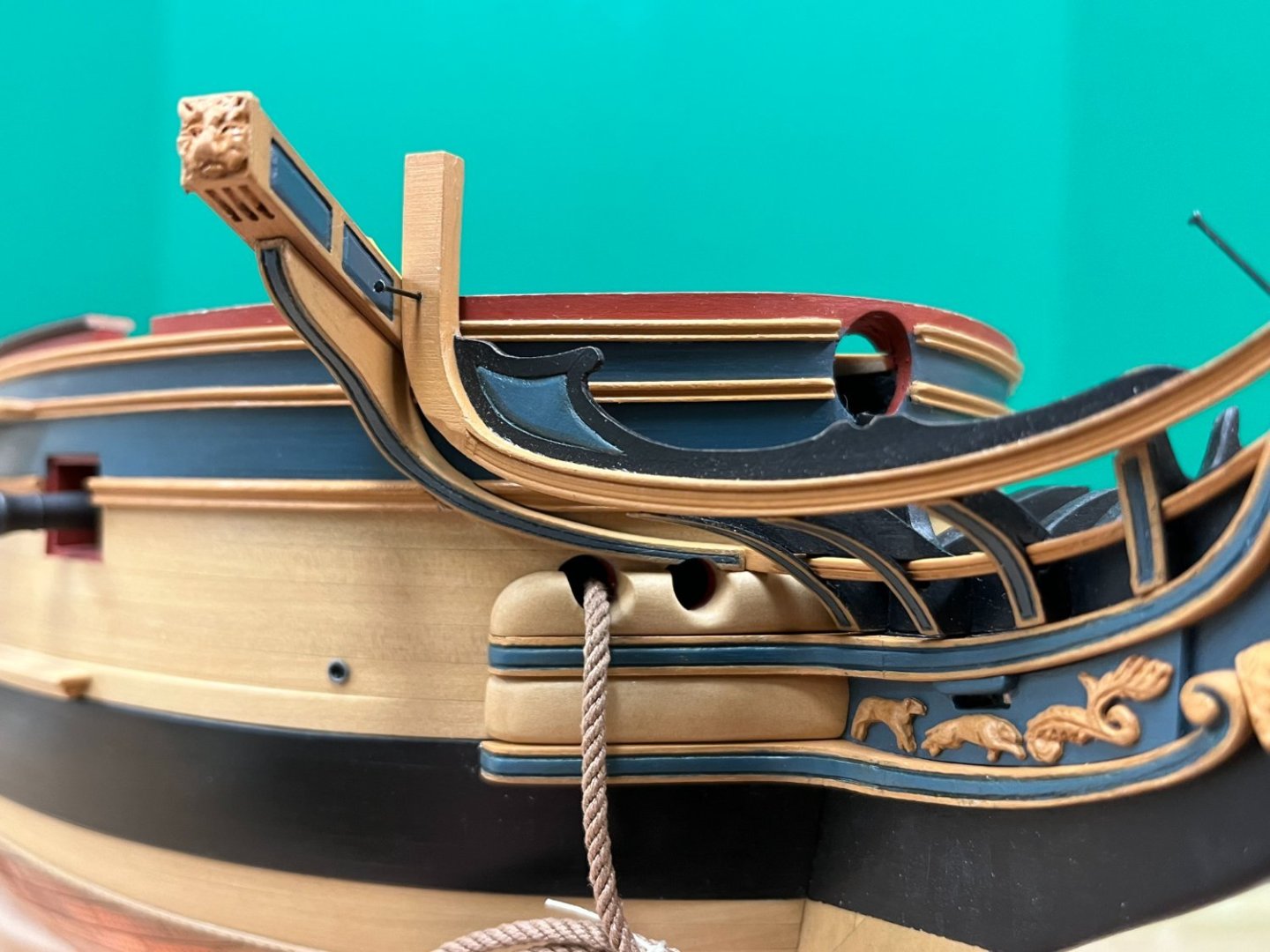
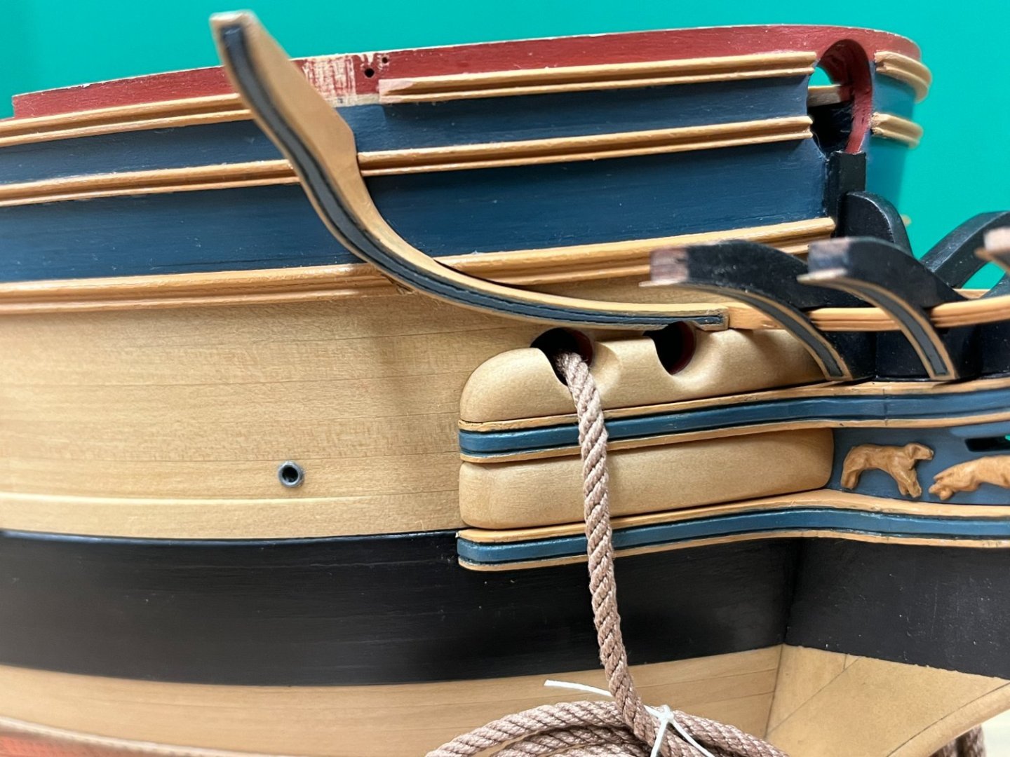
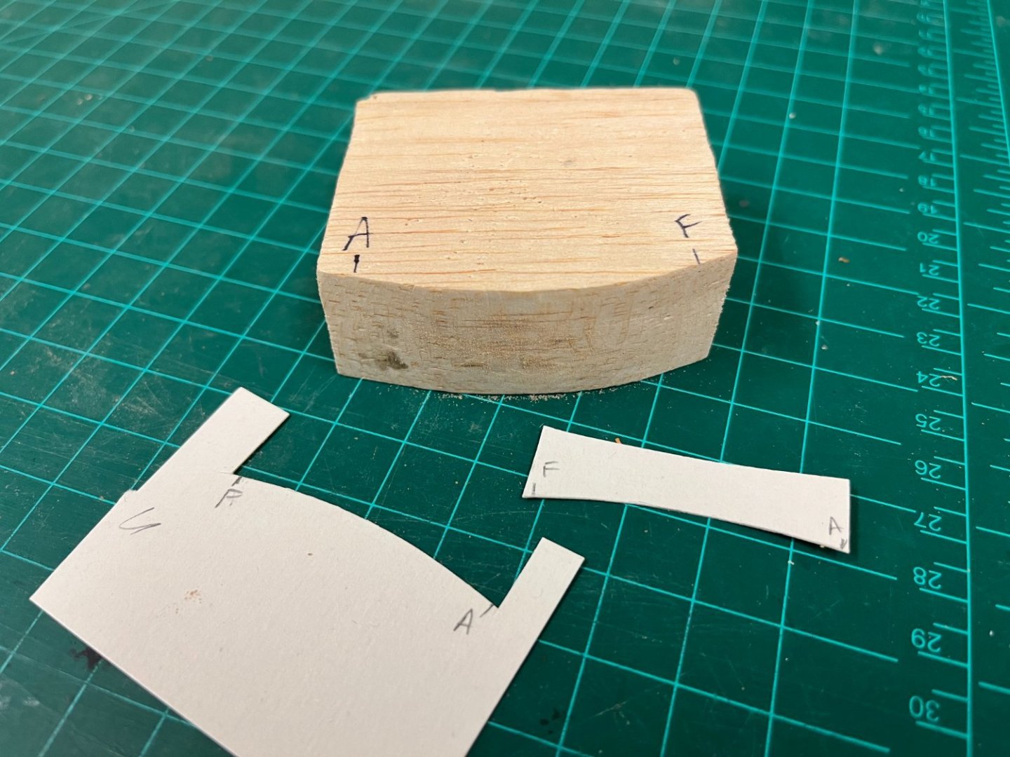
The Ekeing and Cathead supporter: The Ekeing is a detail as presented in the kit that consists of a simplified approach consisting of cat head supporter and ubiquitous white metal moldings. I was determined to make this as prototypical as I could as shown on the plans. Studying numerous contemporary models, this is a detail that seems to vary quite a lot, and I'm unsure whether this varied significantly from ship to ship, or whether the model builders took their own simplified approaches. The following photos of Minerva helped a lot in visualizing this complex shape consistent with the original plans (photos are my own taken at the Rogers Collection). This was a very humbling experience and definitely one of the more challenging pieces to make, requiring many hours of fiddling and sanding. In short (!) , the Eking and cathead supporter needs to meet the following criteria: Narrow from 3mm to approx 2mm at the middle rail to butt into it cleanly Follow the curve of the hull Extend the graceful curve of the middle rail up to the cathead when viewed from the side Be positioned such that the cathead sits snuggly against the top of the main rail, and is perpendicular to the hull Follow a smooth curve outboard from the cathead to the lower rail, the ekeing curving forward almost immediately below the cathead Pass just upward of the outboard hawse hole, but cross the inner....(differing from Minerva above) I had a couple of abortive attempts which while failures, were very helpful in helping me understand the approach described in TFFM Vol 2. The best piece of advice here is focus on one curved face at a time. A cardboard template was made to approximate the profile (this was initially estimated using the spare metal molding strips which work well for this). (Note: In the photos below, the various rails have been cut out to allow placement of the final rail. (When the template was made this had not been done which made this a little more challenging and subject to approximation) The profile of the hull at the bow was taken using a profile gauge and transferred to block of balsa. The ekeing template was transferred to some 5mm pear sheet and cut out leaving quite a bit of excess. The hull profile was then introduced onto the inward face. The shaped balsa block helped a lot in this exercise to allow frequent validation. Once the inner profile had been finalised, the card template could be used to fine tune the shape. This has to be transferred onto the curved surface that will sit against the hull, and it important to remember that the profile on the outboard face will be different because the shape will follow perpendicular to the interior face (i.e. the hull). Some excess was still left here to allow additional fine tuning. The top of the profile was then thickened using some more 5mm pear, and the cathead supporters roughly shaped and glued into place. The cathead supporters were attached perpendicular to interior face, not the exterior face. This rough structure can then be further fine tuned, again using the template on the inner surface and ensuring that the top and bottom face are perpendicular to this along its length. Following the advice in TFFM, The sternmost face was worked first, and once finalized, the inside curve was worked using the outside as a guide. Once these had been completed, the outboard curve following the underside of the cathead supporter was introduced. The lower version shown below still required a lot of fine tuning on the model. Once happy with the shape, the position on the model could be determined, and the decorative rails cut to allow the ekeing to sit flush against the hull. This was definitely a little nerve wracking and will require a little touch up when all is said and done. (The outer surface profiling was not introduced until after this work had all been done and position finalised - these still require some finishing as these photos embarrassingly highlight...) The end of the ekeing also needed to have the shape of the hawse hole introduced onto its lower edge to open that up.To allow the position to be determined, the catheads also needed to be madeup. The "cathead" decorations on the end was made from polymeric clay and followed the very nice original example originally on Trincomalee and other contemporary models - they look a little more acceptable at a distance! Not much else to comment on other than the dimensions and decoration were estimated from the original plans and inspired by contemporary models. These will get further attention in due course. The upper rail is still just pinned in place and will require the top to be shaped prior to final installation. Overall, I'm very pleased with how this came together, the various lines seem to flow quite nicely when viewed from the side which was a goal entering into this. The plansheer, ekeing, catheads and upper rail are all still dry-fit at this stage....but think I can move forward with more confidence.


-
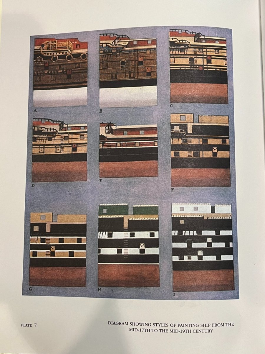
The following illustration comes from Old Ship Figure-heads and Sterns by L. G. Carr Laughton (1925). Think this summarizes the trends in ship colours nicely, and is not identified as nation specific. Unfortunately, no specific dates are provided, but that seems reasonable as changes would likely not be introduced instantaneously, and there were very likely exceptions. The one takeaway is that red/yellow ochre went through various interations, white was gradually introduced as a decorative element (pin striping on the edge of bands) and finally became prevalent along with green, likely becuase of paint technology/cost evolution.

-
some masterful work there David, know how long that must have taken! You've achieved a very authentic look, nicely done!
-
Nice plan! Do you know if Indy retained the upper wale from when she was a 64 when she was razeed?
- 648 replies
-
- 3
-

-
- Indefatigable
- Vanguard Models
- (and 1 more)
-
Its a real shame that display is only temporary, everything just fits together so well, just amazing the life you've built in.
- 200 replies
-
- 5
-
-
- Transport No. 103
- Hasegawa
- (and 4 more)
-
Looking very nice Mark, good to see you back at her.
- 505 replies
-
- 7
-
-
- vanguard models
- Sphinx
- (and 1 more)
-
Looking great Kevin, nice paint job. When I first saw the pictures it looked like the upper hull was blue, but its clear that's just lighting!
- 443 replies
-
- 6
-
-
- Indefatigable
- Vanguard Models
- (and 1 more)
-
Good question Allan. James is probably spot on that for many kit makers it would be an unnecessary complication and would not be a big deal for most modelers, so it is understandably omitted. What is a little more surprising is that some of the more complex (i.e. expensive) POF kits (e.g. CAF Grenado, Bellona) do not seem to account for this in what would otherwise seem to be very comprehensive and well laid out kits. Its a small detail, but one that makes for a more pleasing model.
-
Very nice Henke, your Agamemnon has a very authentic look to it.
-
Thats exactly how I made the scrolls Dave, I tried to include the detail of how these were made in my log. It was something that scared me off for a bit, but of course once you get going, it tends to come together after thinking things through. I have not tried scraping profiles in the supplied walnut, but I suspect the grain may be too big. Pear or boxwood is very close grained and ideal for this type of finish.
-
HMS Victory Renovation - Outer Planking Removed
Beef Wellington replied to Steve20's topic in Nautical/Naval History
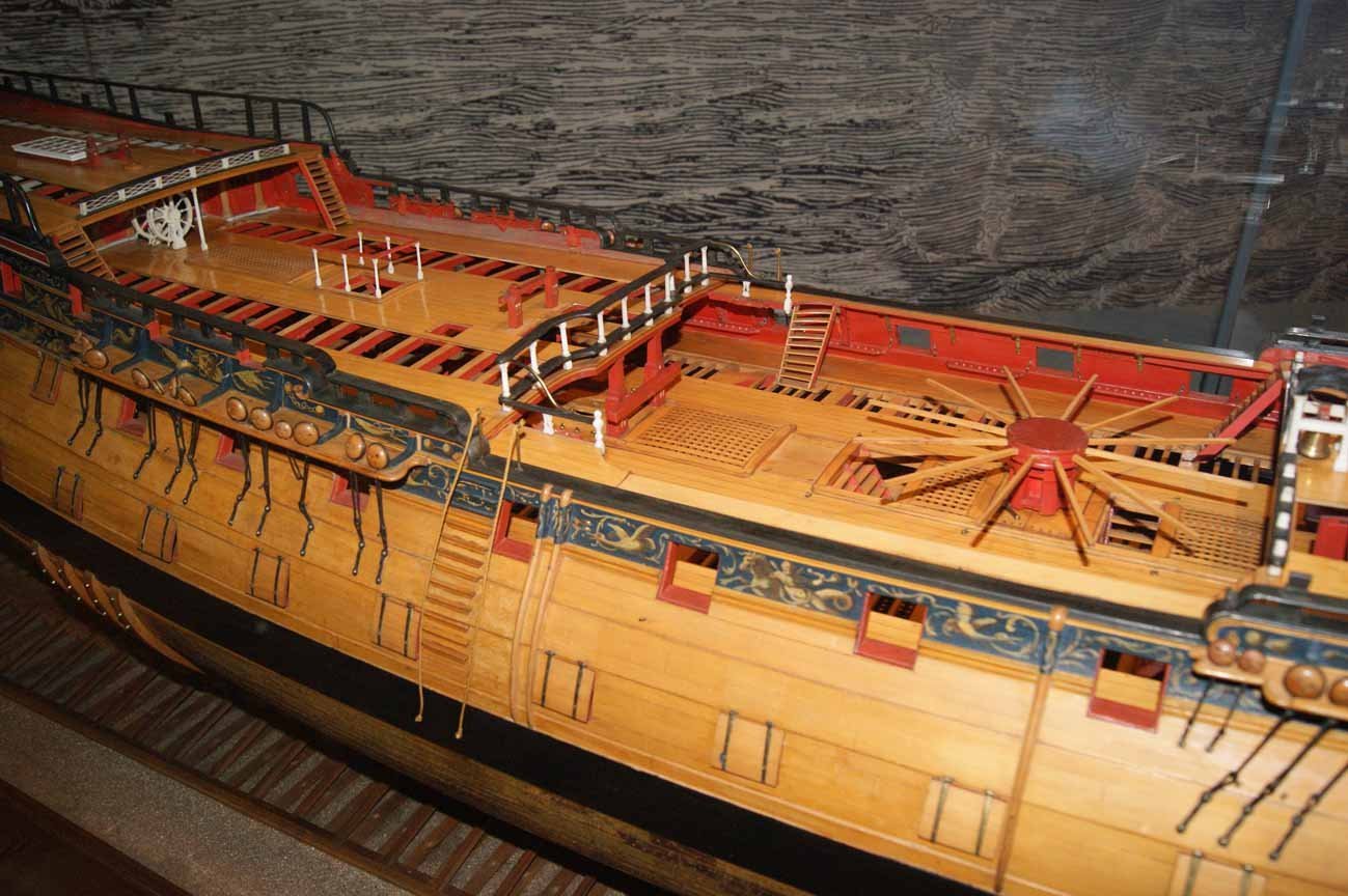
Thats the 'wrong' Foudroyant...it's actually the frigate Trincomalee, which was temporarily named Foudroyant before reverting back to her original name...and of course is now restored and berthed in Hartlepool as a museum ship. -
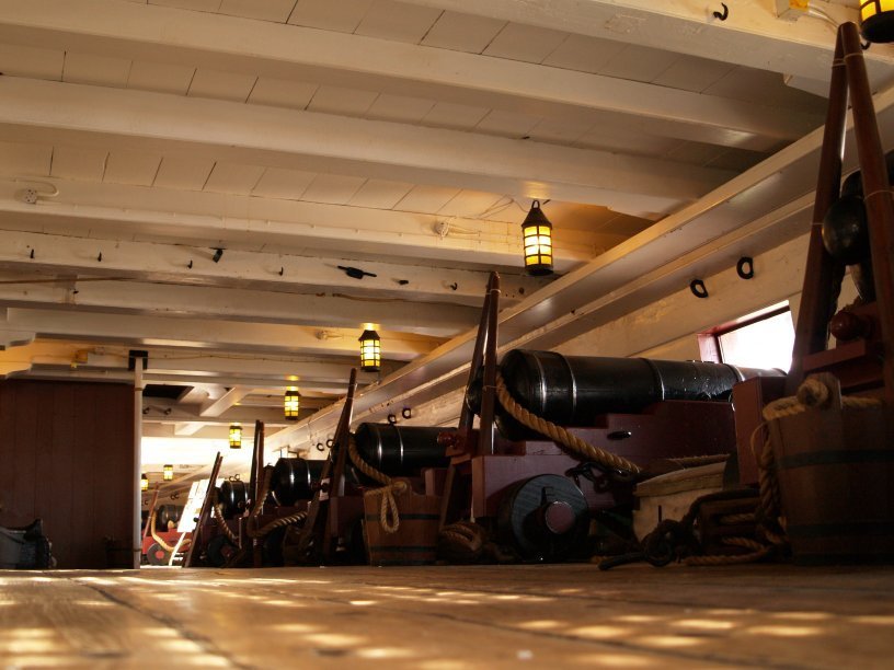
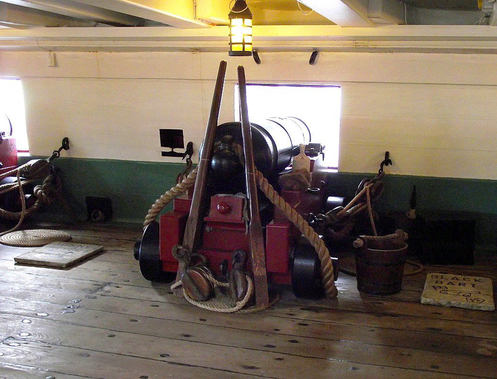
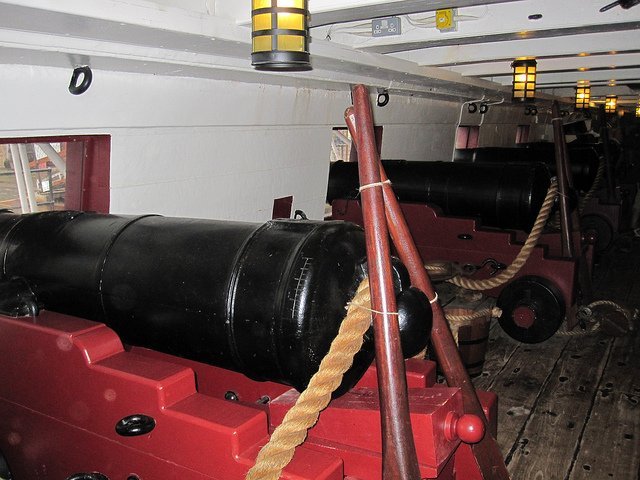
Think photos of the actual items may be clearest. These are of Trincomalee and show them running the full length of the deck. Given that the strakes directly under the beam would not really be seen, there is opportunity for simplification on the model.
-
HMS Victory Renovation - Outer Planking Removed
Beef Wellington replied to Steve20's topic in Nautical/Naval History
I think you have to be careful here...this seems to be a common mis-perception, especially in the US. It suggests that somehow ships just kept getting built until suddenly...surprise...there were no more trees left. While clearly the construction of ships would reduce the supply of specific timbers that require substantial time to replace, and required significant forest management, the impact of other factors were far more impactful in general (urbanization, increasing arable land etc which had been a factor for centuries before the 'golden age' of sail, and continue to be issues today. Who chopped down Britain’s ancient forests? | Aeon Essays -
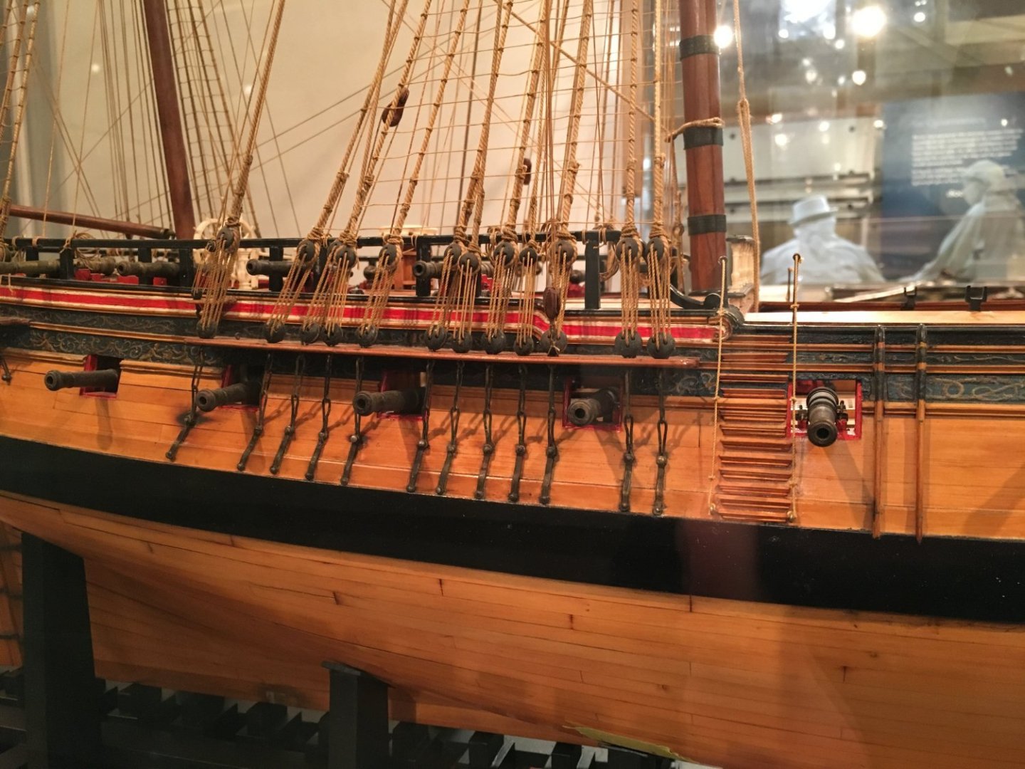
Hi Dave, I think you have some latitude, and I don't think anyone can definitively say how it was. Included below are some pictures I took at the Annapolis museum, so sorry for the poor picture quality. You can see that the frigate does not have any port lids at all (not sure which model this is), and the two decker shows ports only in the more extreme end of the hull, i.e. open around about the open deck. Despite Chris beating himself up unecessarily, I don't think the kit representation is really that out of whack with historical likelihood. My suspicion is the port lids are added primarly where there would have been a permanent or semi-permanent cabin for obvious reasons.

-
Hi Stergios, hopefully I can answer your question. The problem is that at real world scale, the lines that are secured to the braces would not pull the stays out of their natural position because they are so much more massive. Without dealing with this at this scale, the braces would pull the stays out of their natural line which is what I wanted to avoid. The approach used weighted the stays down enough to keep them in their natural position while the braces were given a little tension, then dilute PVA was brushed onto the braces so that when dry, they retain a 'taught' profile, even though there is no longer any real tension. Seem to recall I just used plastic clips or simply tied other thread around the stay to counteract the force of the braces. In the situations where the brace goes through 2 blocks on the stay, these were handled sequentially, waiting for the PVA to fully dry before moving on. Good news, if it doesn't quite work out as you'd like, you can re-wet the line and repeat the process until you're happy.
- 800 replies
-
- 5
-
-
- snake
- caldercraft
- (and 1 more)