Beef Wellington
-
Posts
2,249 -
Joined
-
Last visited
Content Type
Profiles
Forums
Gallery
Events
Everything posted by Beef Wellington
-
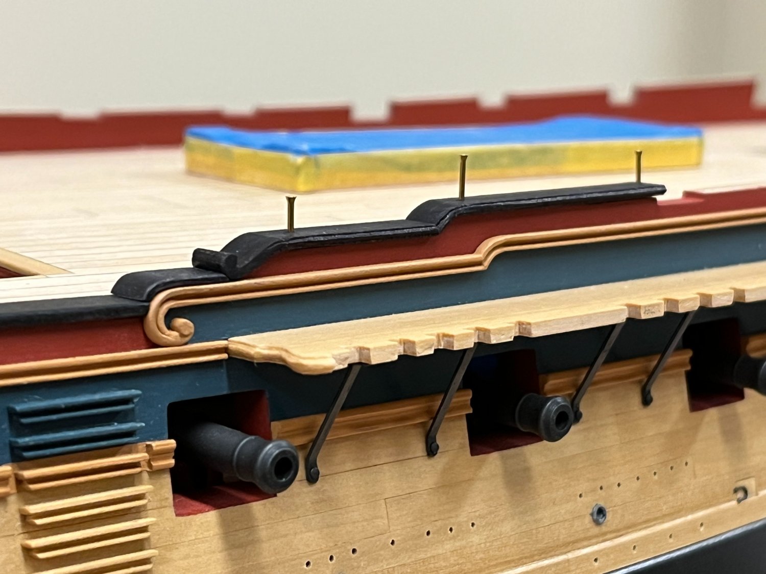
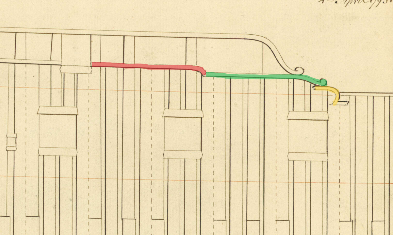
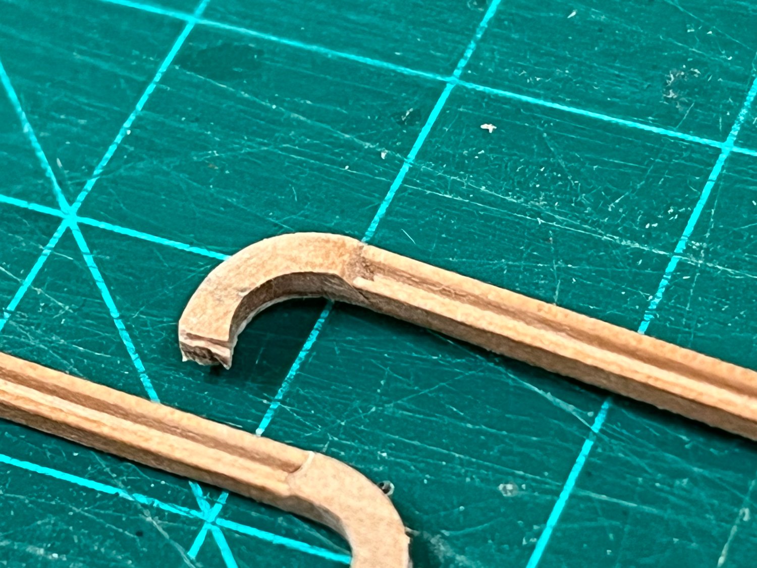
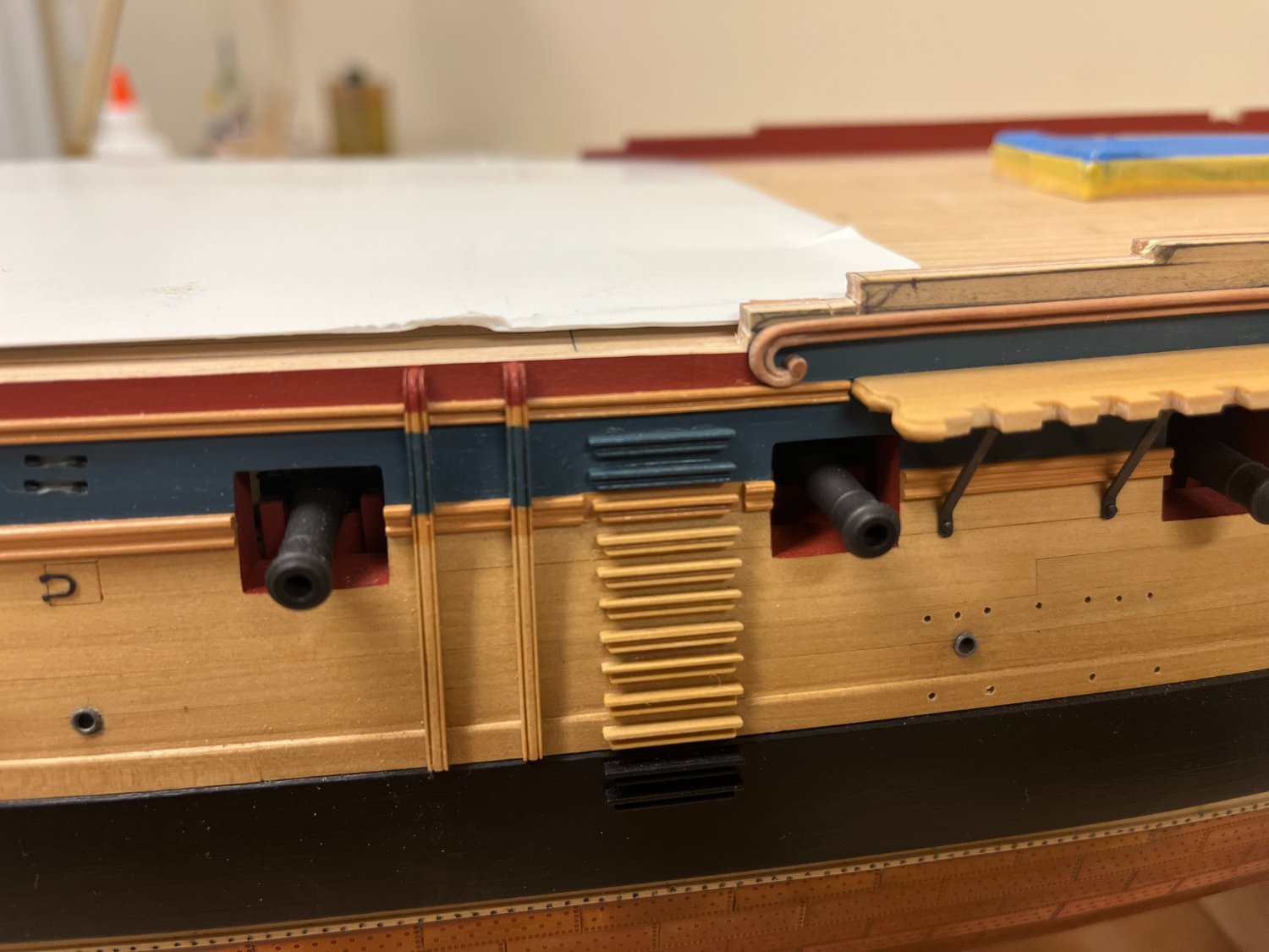
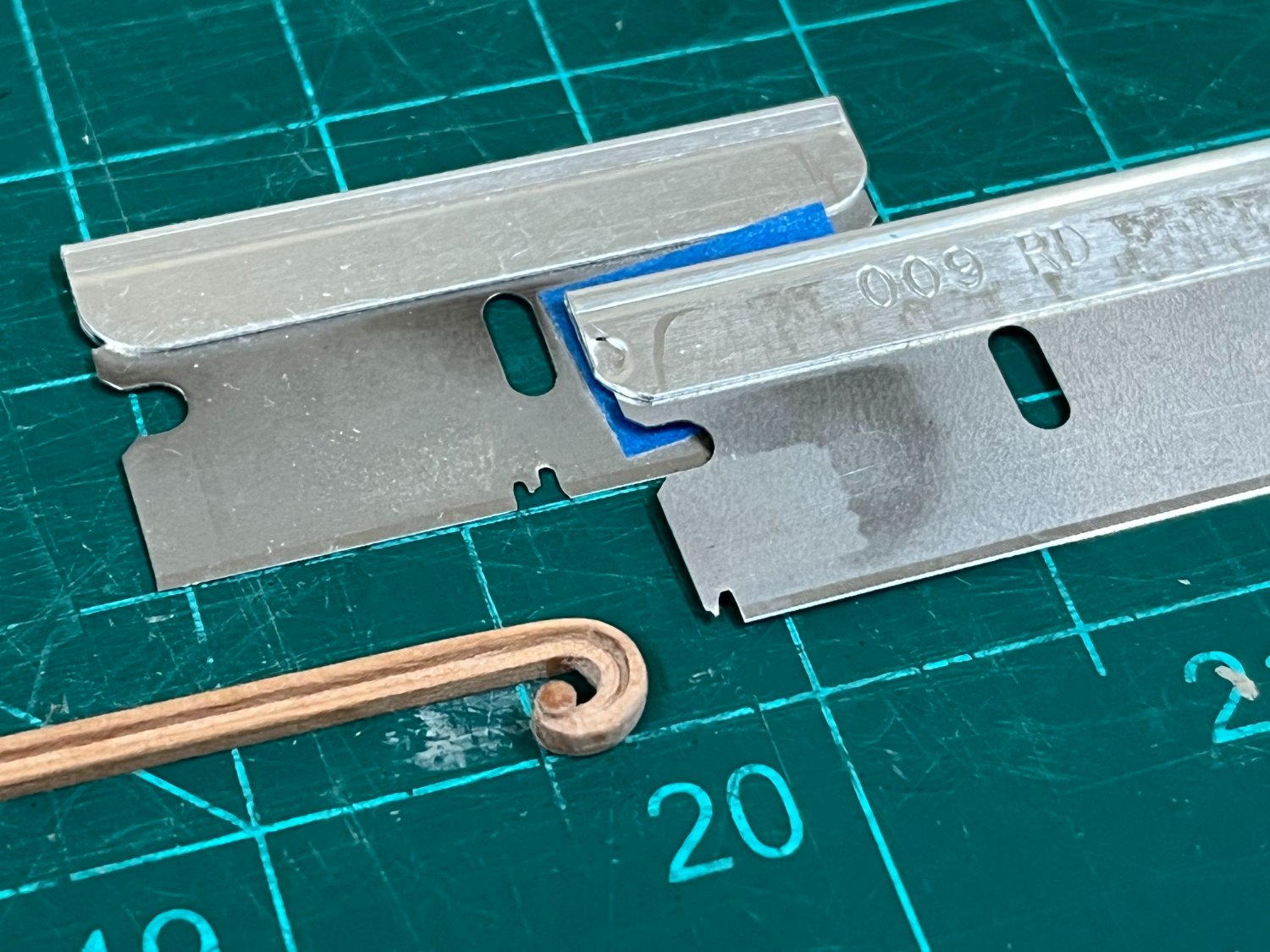
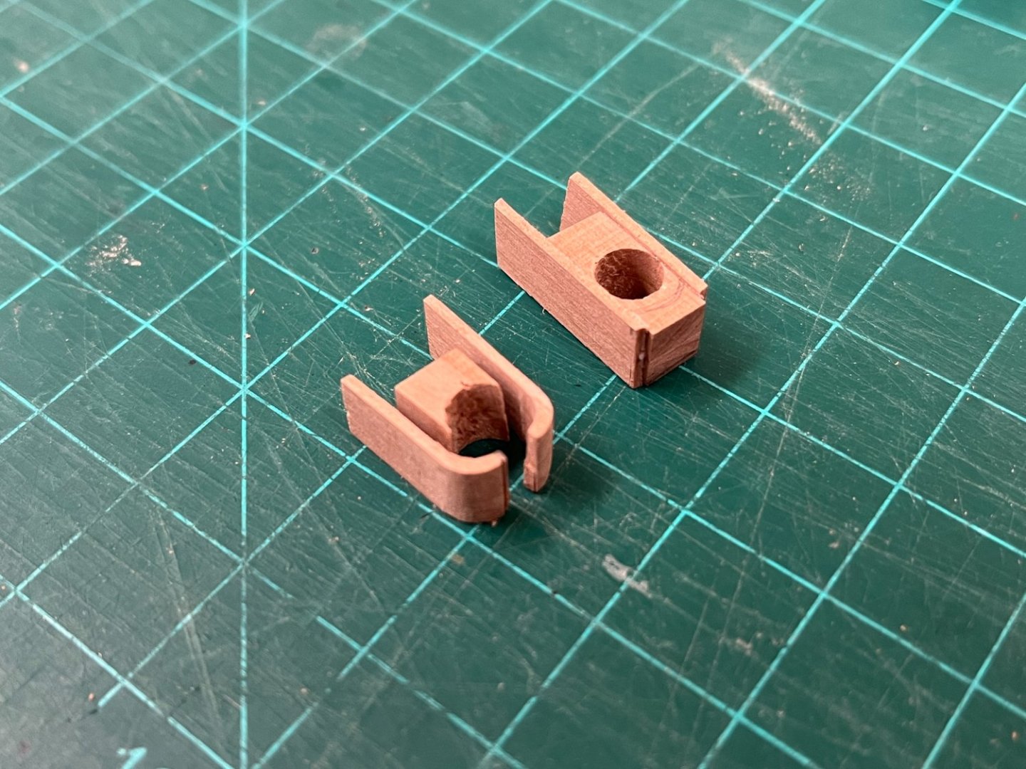
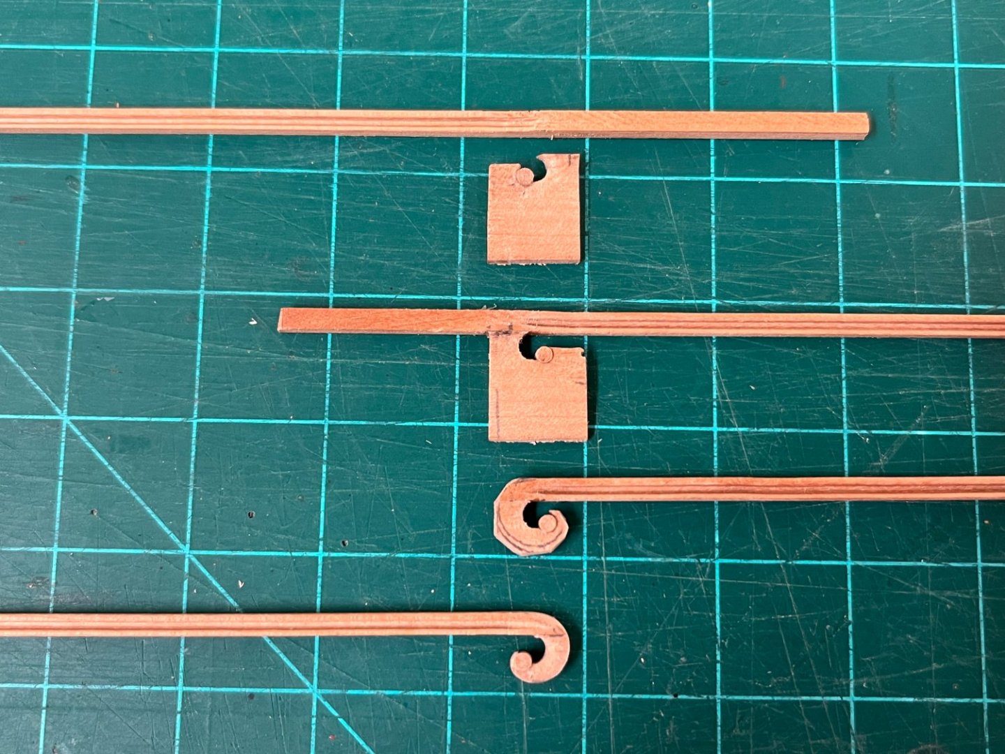
 @Wayne - I miss seeing progress on your Enterprise, hopefully soon (?) That will be a beauty! @Mark - I aspire to be able to do what your are achieving on your excellent Le Rochefort build, would love to do a POF one one day and I need to bone up on basic woodworking techniques first. Quarterdeck plansheer (capping rail?): Work can now commence on the quarterdeck plansheer given that the upper hull profile is finalised. This will be a rather long process given the many breaks in the smooth run of the plansheer. Starting with the quarterdeck, a 'lego' type approach was taken to build items individually and then combine on the hull. While more time consuming (what does that matter!), my feeling was that it would give more control over the outcome. 3 pieces will be needed, and will be referred to rather unimaginatively as pieces 1,2 and 3 becuase I have no idea how better to refer to them. (Given that 2D plans don't seem to translate 3D, I have attempted to study as many pictures of contemporary models, plans and the many high quality builds here - all I could really glean was that there are many ways to approach this, and this approach is probably a compromise.). This is the area I'm talking about: Piece #1: from the gunwale, around the main drift volute to the terminaton of the scroll decoration (yellow) Piece #2: middle section with a scroll type detail on one end (green) Piece #3: section following the profile caused by the break of the quarterdeck drift rail to the main rail (red) Construction of Piece #1: Without anythig sufficient thick to hand, 4mm pear sheet wood was laminated together and ever increasing holes drilled until 6mm had been achieved (curvature of volute top). A hand drill had to be used for this as I don't have a drill press. Care was taken to ensure that the grain was running perpendicular to the hole which I suspect will give the strongest final result. The hole was then very carefully reduced on the circular sander until just before the hole was opened up. (I managed to do this on both sides which allowed 2 sections to be made from one hole). 1mm thick strips were then attached on each side, with PVA glue only being used on one side and clamped. Once thoroughly dry, the piece was roughly shaped toward its final form of a 1mm thick curve. The part was cut in half, releasing each curved section for final finishing using sanding sticks. (Note: the downside of only having a hand drill means it is very difficult to get perpendicular holes, and the top block shows a failure to allow for this). Construction of Piece #2: The scroll detail is probably the most complicated item to deal with. To start, sandpaper wrapped around a section of 6mm dowel and a curved profile introduced into some 4mm cherry sheet. The section was then temporarily glued to some scrap to allow the excess material to be carefully removed on the circular sander, (a technique that is becoming very familiar!). The two halves were detatched, and glued to a pre-shaped section of 1.5mm thick pear because the curve of the hull is a factor. The first photo below shows this starting point from which the final form was shaped. The second photo shows progress mid way through shaping. To account for the scroll detail, a circular needle file was used to introduce a profile into which some pre-made 1.5mm pear dowel could be glued. Construction of Piece #3: This was constructed in exactly the same way as piece #1, only difference being that 1.5mm was used for the plansheer. Once each step was completed, the pieces can the be individually fine tuned prior to installation, each having deliberately been made a little long. A profile was introduced in the usual fashion using a profile cut into a safety razor blade (see final pics below): The curved sections proved not unexpectedly to be the most challenging to fine tune. The aft end of piece #3 terminates in a gun port which would be relatively easy to finish when the time comes, so this was fitted fitted first. The most worrying thing here was coping the angle of the curved portion to tie into the aft end of piece #2 to avoid a time intensive redo (65deg was found to be the solution). Piece #2 was then very carefully shortened until it sat correctly. Before piece #1 could be finalized, the gunwale was made up to ensure correct positioning and shaping as piece #1 will butt up against both. And the results... Everything is dryfit only for now. Pins were used to temporarily hold the various sections in place, these can be easily filled, although efforts were made to place these where the timber heads will cover them. With the exception of the gunwale, the plansheer sections have not yet been painted but have been coloured with artist pens to help my eye determine final proportions. The final shot below shows how even the relatively minor curve of the hull at this point needs to be accounted for. I have a lot of work ahead of me to finish off the other areas so will likely be a while before another update, but must confess to be being very pleased with the way this turned out.
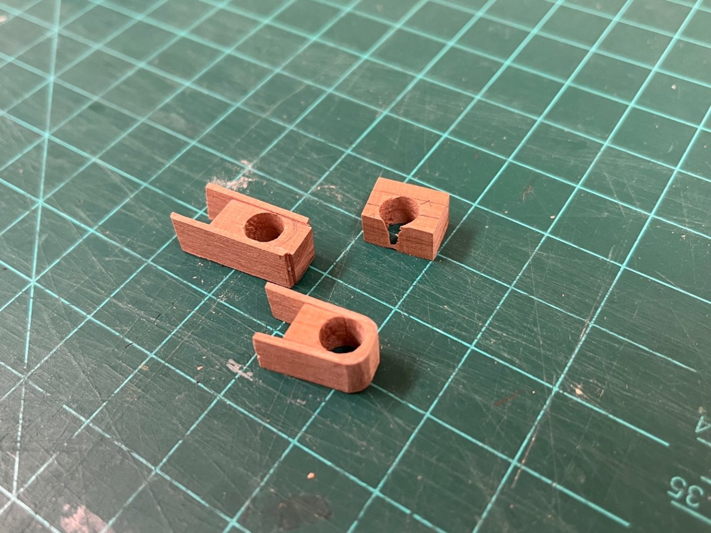


-
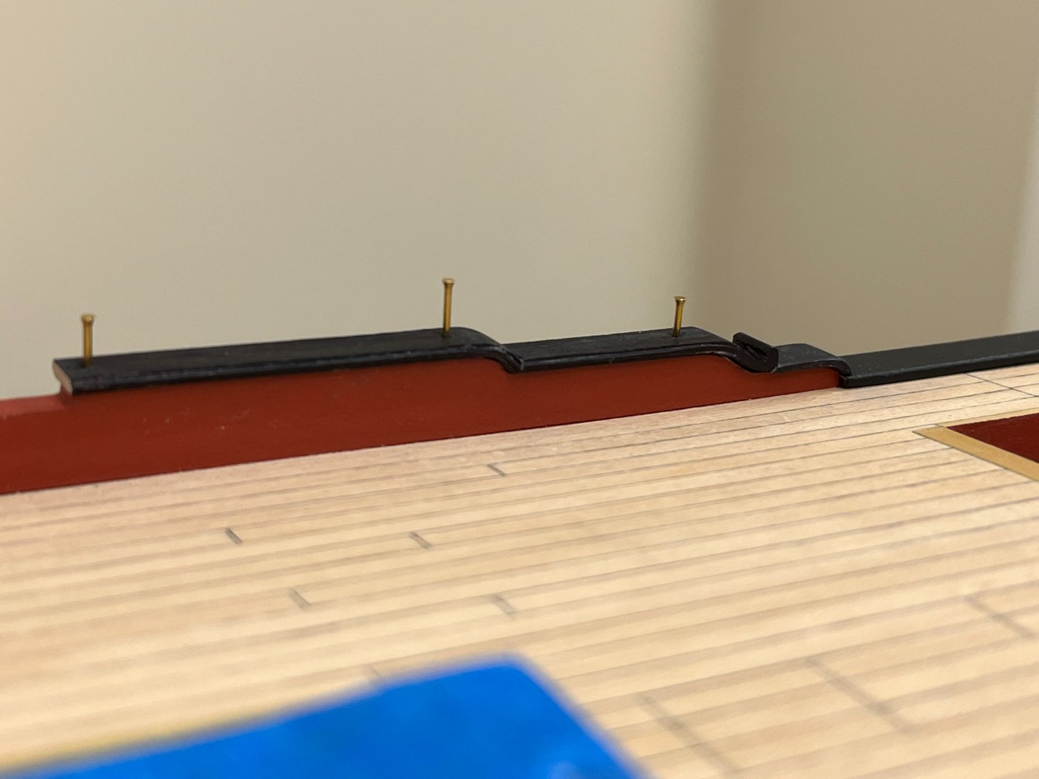
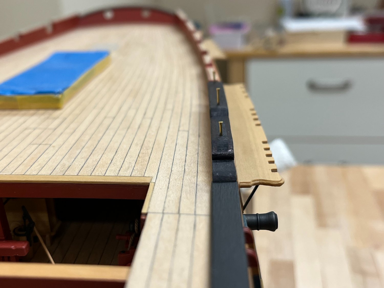
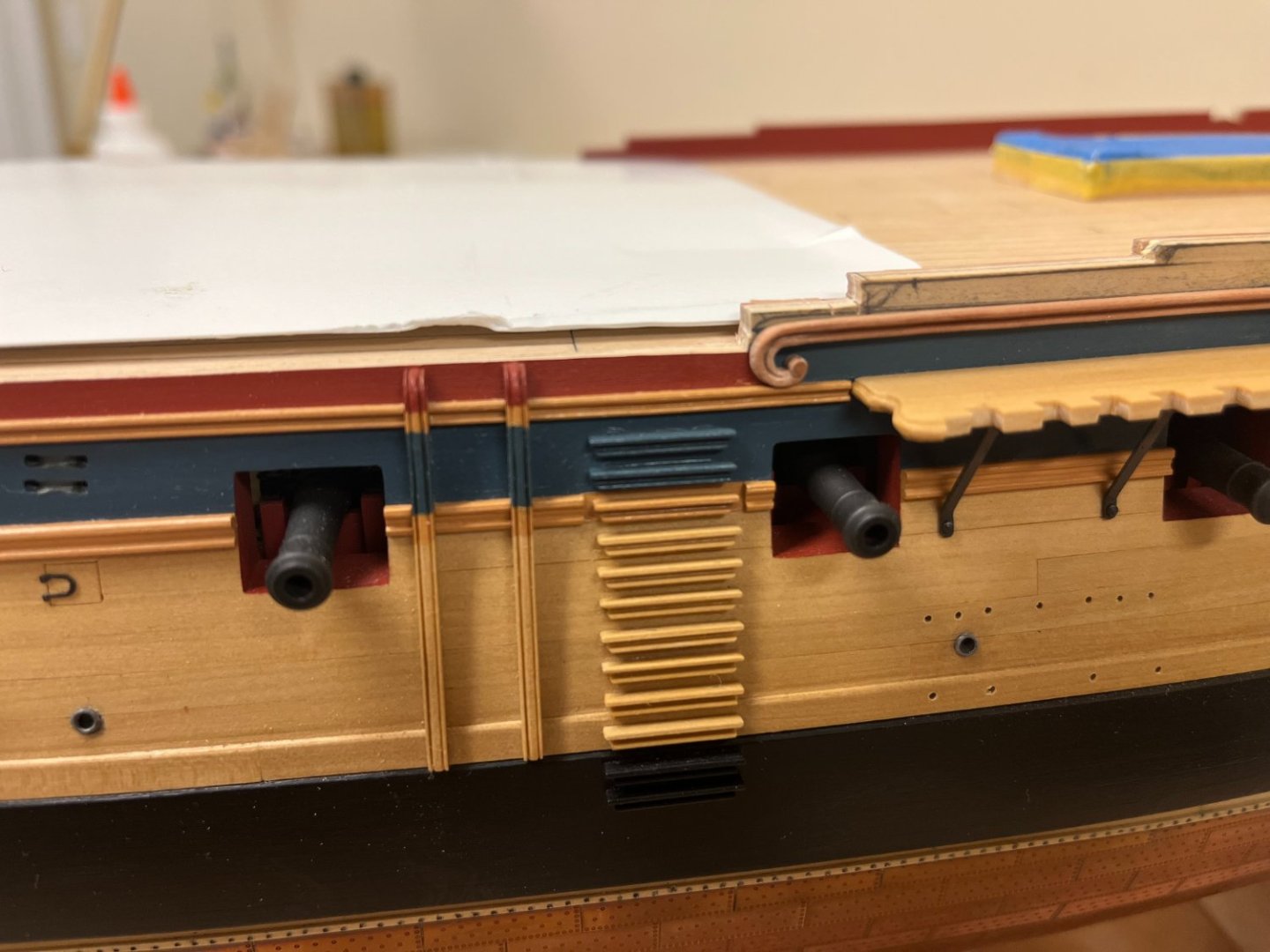
Thanks everyone for the continued interest. Catching up on a couple of items before moving onto the more complex task of the sheer rail (plansheer?, capping rail?) which will be the focus of the next update. The profile of the hull has been fine tuned, all of the gunports have been cut, fettled, and the upper hull painted. The only remaining task with the rails is to create the transition from the quarterdeck drift rail and the main rail. A similar approach was taken to that used for the volutes to introduce the curve, but a 45deg joint was used to try and leverage the pre-scraped profile as much as possible. The profile was then introduced into the curved section as described above for the volutes. Once complete, this section was joined with the volute section before gluing in place. And the rails finally attached the hull. The curve of the forward end of the bulwark follows that of the volute. Visually its important (to my eye anyway!) to ensure that all of the rails and top of the hull are parallel, and follow the sweep of the main wale. Placement of the rail also helps determine the appropriate final profile of the upper hull.


-
You have a very fine model coming together here Brian. Especially like your photos of the stern, the colour combination is very pleasing to my eye! Will be following along from here...
-
Just found you again BE, thankfully before you're finished. The small boats are fascinating and this is definitely one that has tempted me. I'm amazed that the flying transom only became detatched once, and have no doubt that the silk purse is not far away...definitely agree on the replacement of the transom panel.
- 106 replies
-
- 3
-

-
- Admirals Barge
- Vanguard Models
- (and 1 more)
-
Looks great. Was the primer that you used matte? That would make seeing any imperfections that mush harder, as it looks like the finish has a satin finish which would show these much more.
-
Looks great, definitely intriguing to see how this beauty develops!
-
Great result on the binnacle, and love those close in deck shots which really show the scale and detail authenticity. BTW, love your statement "Everything I attempt is taking a lot longer than envisaged."...can certainly relate!
-
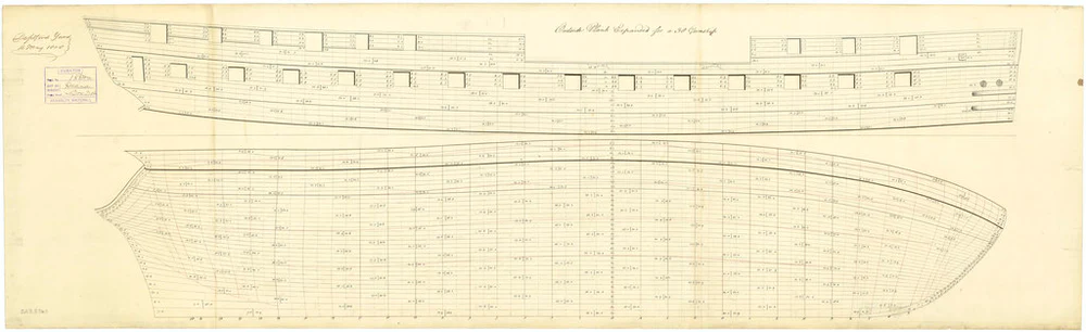
Quick update - even though I've been gathering the info above for some time, immediately after making this post I stumbled across another plan that I had not seen before. (Available at Ship plan of HMS 'Diana' (1794): expansion of outboard works (rmg.co.uk) ). Thankfully this supports the thinking outlined above, but makes me happily retract the statement that there are no plans of the Artois class reflecting the 1793 Admiralty order for 4 quarterdeck carronades. Unfortunately I can't find a high resolution version to be able to read the text, but this planking expansion clearly shows the 2 carronade port alignment. Fortunately, the approach I've taken described above has been validated and I can continue with a clean(er) conscience. Of interest to other Artois builders, this adds yet another option for the bulwarks showing a fully built up bow, and squared profile of the quaterdeck not commonly seen. Ship plan of HMS 'Diana' (1794): expansion of outboard works (NMM J5533)
-
Hi Beez, think your toned down stern is much more in keeping. You're making great progress.
-
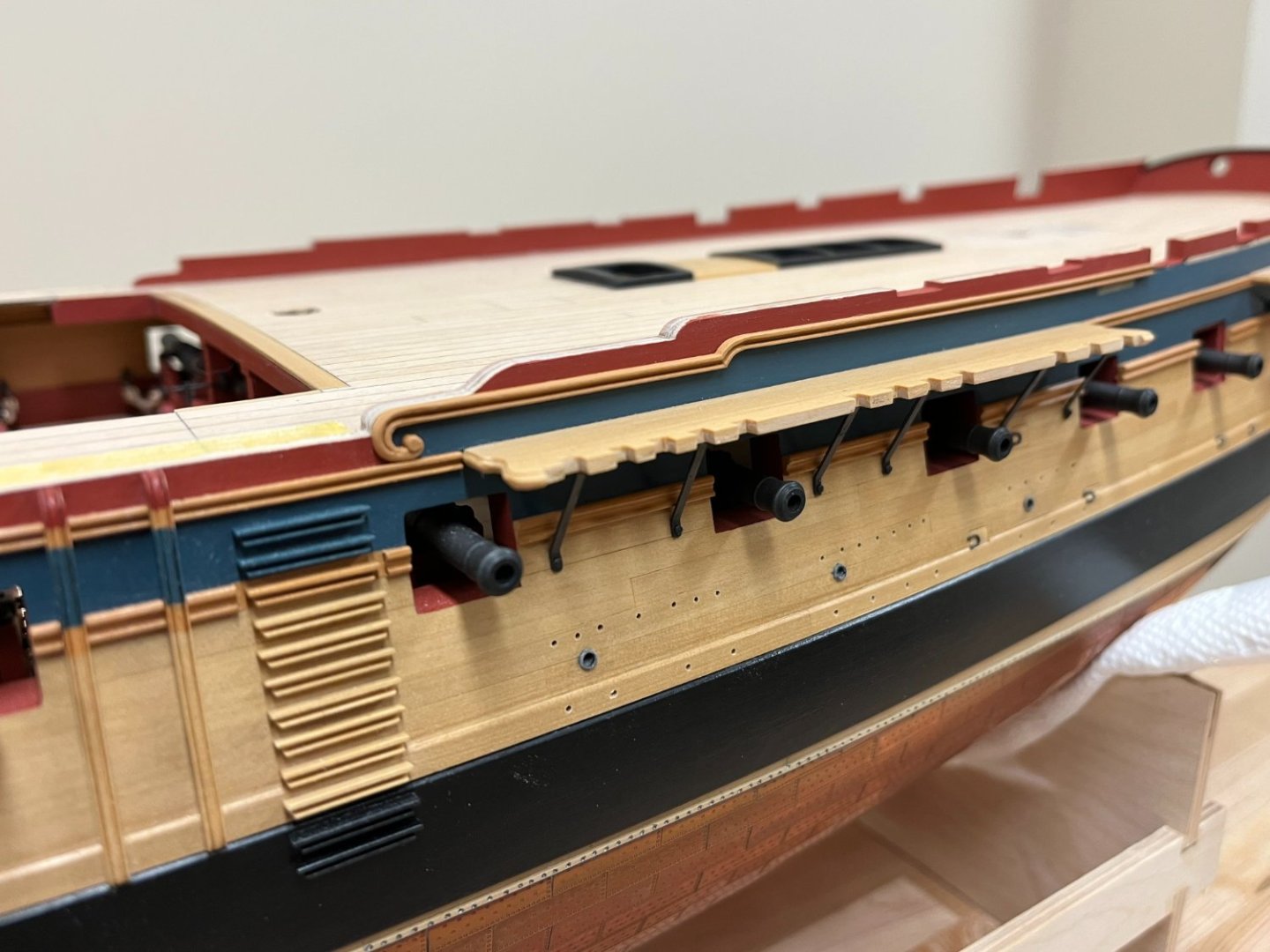
Thoughts and conjectures on 'Jason's' (and Artois class frigate) armament and bulwark configuration: Currently knee deep trying to think through a number of problems making sharing photos at this stage a little premature. I have however reached a stage where certain decisions are required, specifically the armament bulwark gunport/carronade configuration. I very much enjoy seeing other builders' thoughts and decisions on how to build their Artois class frigate, Diana or otherwise, and at the risk of putting people to sleep I'm summarizing my thoughts below. As has been commented many times, much is unknown leaving a lot to builders' discretion, but I think the available evidence suggests that these options can be. Without either the builders or ships logs to shed more light, much will remain conjecture. My goal was to arrive at the most likely (IMHO) scenario for 'Jason' when she was launched, but also not let this get in the way of the model I want to build. (Recognizing of course that certain anachronisms will persist, for example copper plates, armament etc. would not be present at launch). My intent is not to spark debate, but to get my thoughts on paper. 🙂 Chronological timeline of evidence and events: Date unknown: Various NMM models with no armament, pierced for canons with open quarterdeck bulwarks and multiple design differences discussed fully in AOTS. 1793 (NMM Plan Ref ZAZ2383) – open bulwarks with quarterdeck, with more additional exposed quarterdeck timberheads, ports for cannons only (no carronades) March 1793 (NMM Plan Ref ZAZ2341) - Open bulwarks, originally reflects, but reflects updates (likely1797?) showing 6 quarterdeck, 2 forecastle carronade ports March/April 1793 (NMM Wikimedia Commons J5552) – Open bulwarks, reflects 6 quarterdeck, 2 forecastle carronade ports 1st April 1793 (NMM Wikimedia Commons J7737) - Closed bulwarks, ports for cannons only (no carronades) 4th April 1793 (NMM Plan ZAZ2344, NMM Wikimedia Commons J7733) – Framing plan, open bulwarks, ports for cannons only (no carronades) 12 June 1793 (NMM Wikimedia Commons J5549) – Closed bulwarks, ports for cannons, (reflects change for 6 quarterdeck, 2 forecastle carronade ports, as well as subsequent adjustments to gunport position – date unknown). Interestingly also shows the mainmast brace bits moved forward adjacent to the barricade which is not reflected in any other sources. November 1793: Admiralty promulgated Order defines armament: Quarterdeck: 8 x 9lb’er, 4 x 24lb Carronade per Admiralty Order, fo’c’sle: 2 x 9lb’er (Likely long nine chase guns), 2 x 24lb Carronade April 1794: JASON LAUNCHED November 1794: Admiralty promulgated order to replace 24lb Carronades and carry additional 32lb Carronades at expense of some carriage guns. Quarterdeck: 6 x 9lb’er, 6 x 32lb Carronade, fo’c’sle: 2 x 9lb’er (Probably long nine chase guns), 2 x 32lb Carronade 1797 (NMM Plan Ref ZAZ2341) Closed quarterdeck bulwarks shown on plan per current practice (Details of design or build channel and open bulwark arrangement shown). This plan also indicates the more austere square finish to the quarterdeck bulwark in addition to the more ornate version used in the illustration on the jacket and used as basis for the kit configuration. Interestingly, plan indicates that the Foremast of Jason and Diamond were moved forward 6 ¼ inches. Quarterdeck piercings for 12 carriage guns shown as designed/built together subsequent adjustments for piercings for 6 x carriage guns and 6 x Carronades Aug 1798: JASON WRECKED December 1799: All upper deck armament to comprise 32lb Carronades per Admiralty Order, with exception of 2 chase guns) Quarterdeck: 12 x 32lb carronade, fo’c’sle: 2 x 9lb’er (Probably long nine chase guns), 2 x 32b Carronade Decisions and rationale for how to represent ‘Jason’ “as launched”: Bulwarks: Sufficient historical ambiguity to allow the model maker (me) to feel comfortable that both open or built-up bulwarks are historically viable. This short period of a few years when these ships were built was a time when the preference for 'built up' and 'open' bulwarks switched back and forth. The earlier older design variance of open bulwark with exposed timberheads, while intriguing to model, seems unlikely by 1794. Armament: The admiralty order of November 1793 will be reflected as I believe there would be sufficient time to between issuance and launch for this to be reflected. As such, Jason will be equipped with Quarterdeck: 8 x 9lb’er, 4 x 24lb Carronade and fo’c’sle: 2 x 9lb’er and 2 x 24lb Carronade. Gunports: ‘Jason’s’ gunports will be pierced to reflect the armament described above. There are however no (existing) plans that show this configuration (i.e. only 2 quarterdeck carronades per side). In my view, this does not seem problematic: CORRECTED - there is! See post #691 below There was only a 12 month period between the Nov 1793 Admiralty orders to carry 4x24lb quarterdeck carronades, and the Nov 1794 order to carry 6x32lb quarterdeck carronades. Only plans drawn up in this period would reflect this configuration, and given that plans for each member of the class were drawn up pretty extensively in 1793, there doesn’t seem to have been much need to redo. The available plans reflect different things, but it's not definitively known exactly what. Various plans showing the original cannon only configuration show subsequent modifications for the 6 carronade ports, but none show only 4. It seems reasonable that any updates to reflect the 1793 (4) carronade configuration, would likely have been updated again to reflect the 6 carronade configuration after 1794, or just updated to once after 1794. My conclusion therefore is that the absence of a plan showing this configuration does not preclude it. The ports least encumbered by stays were selected, and which are consistent with subsequent carronade layout. Hopefully back to some photo's next update...
-
Thats a nice guide, and the results show you're clearly an old hand at ratlines. BTW - I *think* the tool you show is called a bradawl, but not sure if that name applies to squared tips and maybe others can confrim...in any event, I wish I had one!
- 310 replies
-
- 2
-
-
- Diana
- Caldercraft
- (and 1 more)
-
Hi Sparky, you've made a solid start. I'm not familiar with the kit, but just a suggestion, looking at your pictures it doesn't seem that you have faired the bulkheads anywhere near enough to get a smooth run for the planks. You really want the fairing to all the way to the aft face of the bulkhead so all of the plank face contacts it. I think if you revisited that, it would make your planking a much easier and enjoyable experience.
-
Nice results there David, looking great. Just curious whether you looked at and compared the 'aftermarket' pins provided by Caldercraft, they are much slimmer and proportional that those provided in the earlier kits. I doff my cap to you as well for making 60 of those things!
-
Bit late, but congratulations on yet another fine build, with just the perfect amount of period 'je ne sais quoi' that you excel at!
- 857 replies
-
- 5
-
-

-
- Sphinx
- Vanguard Models
- (and 1 more)
-
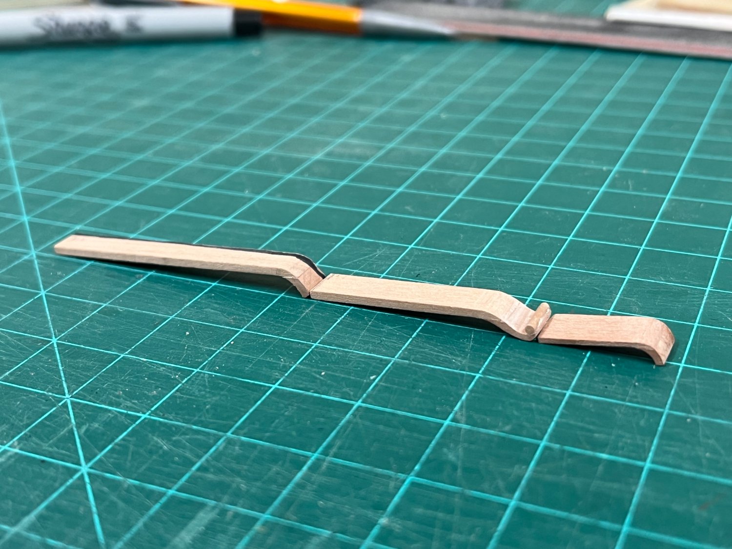
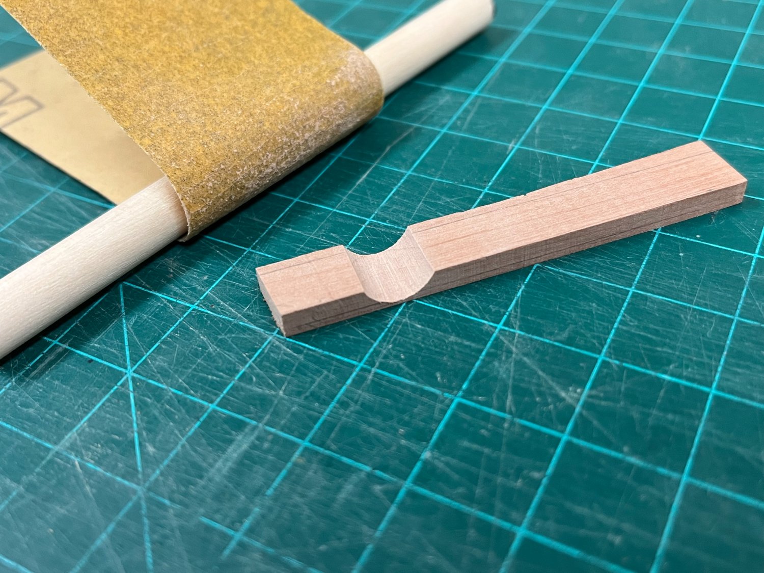
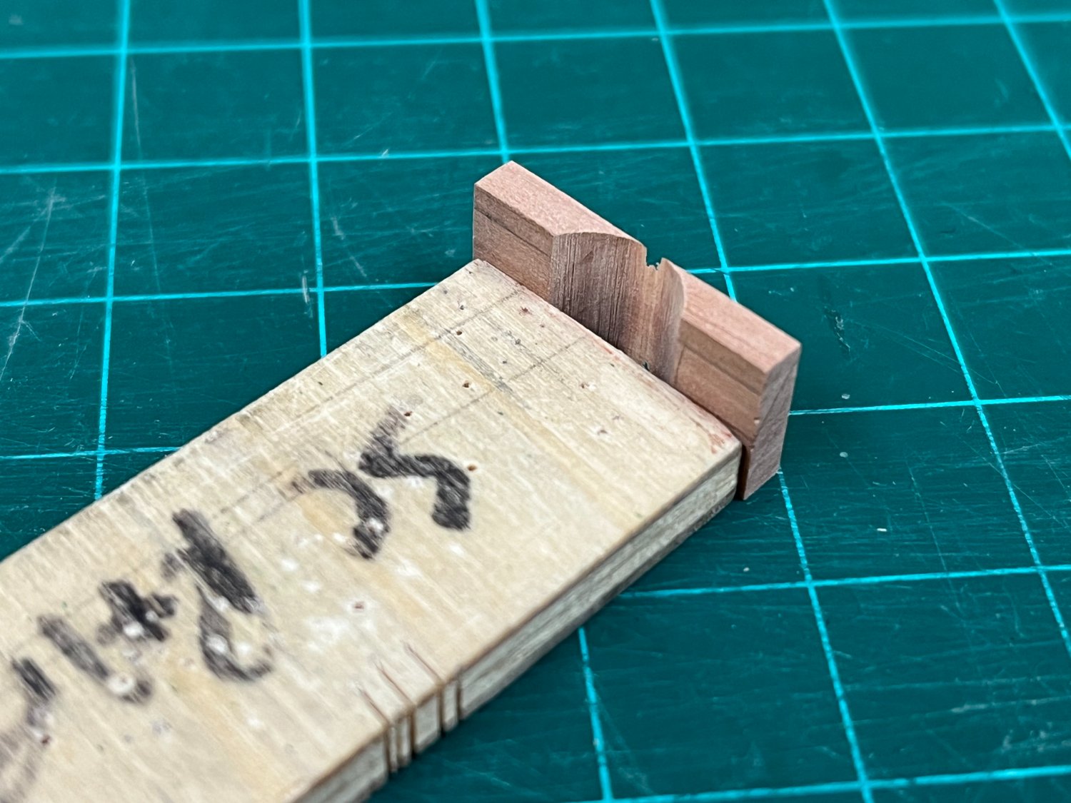
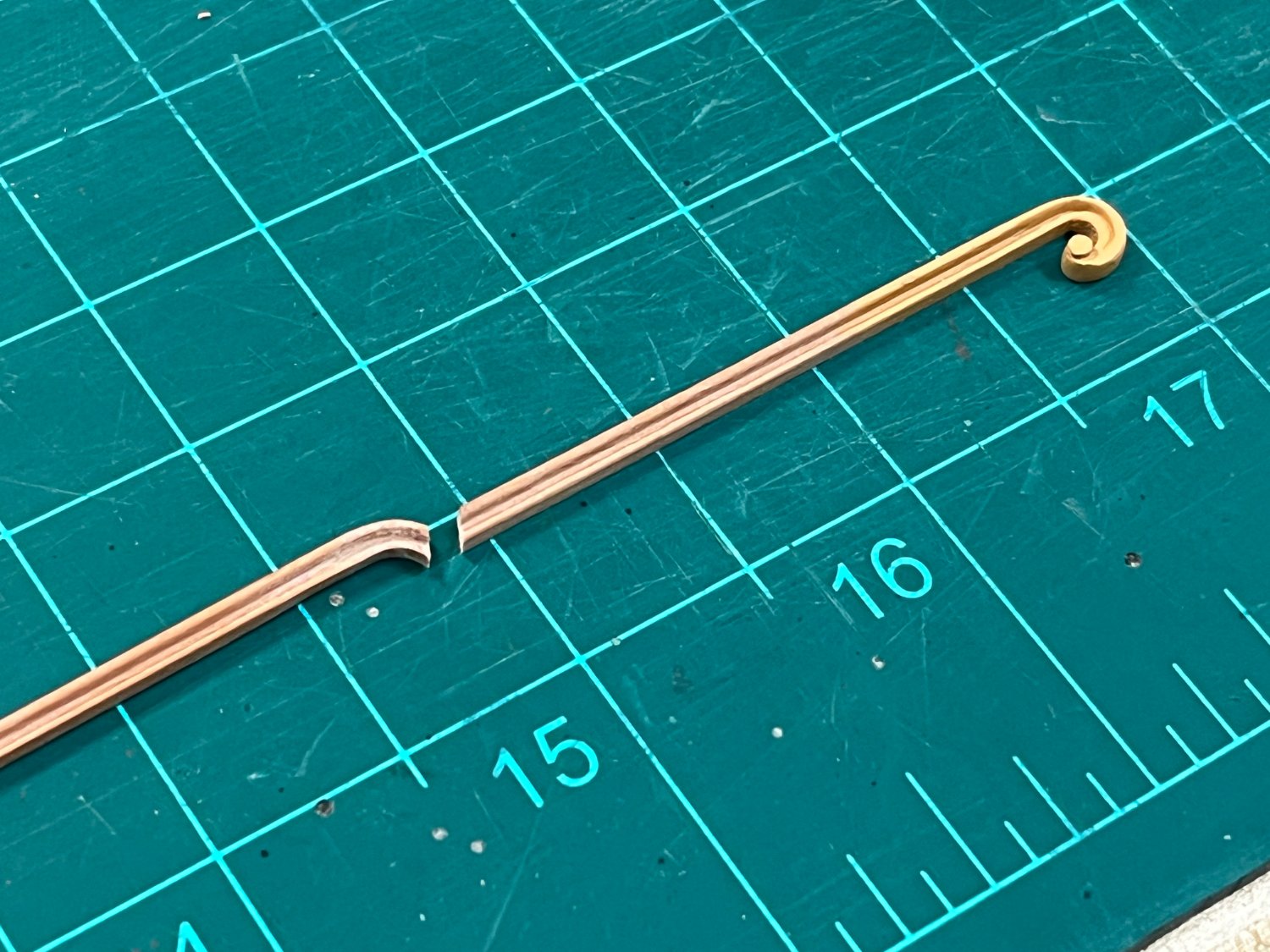
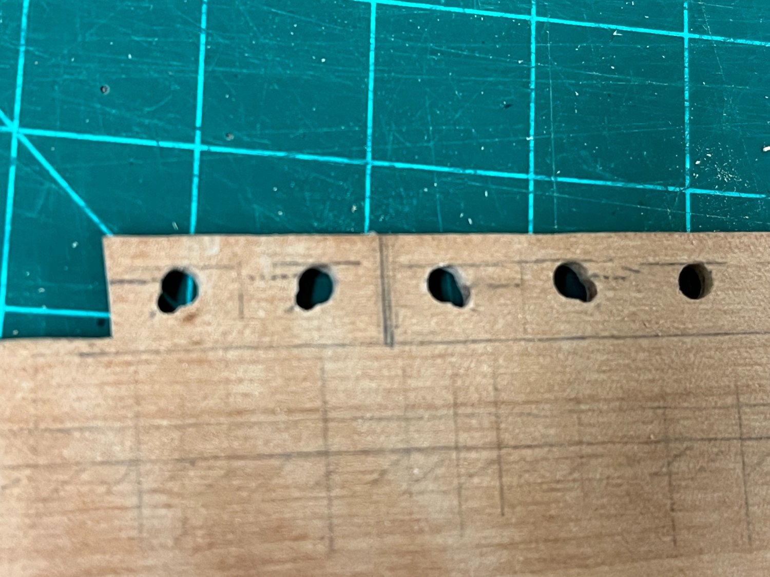
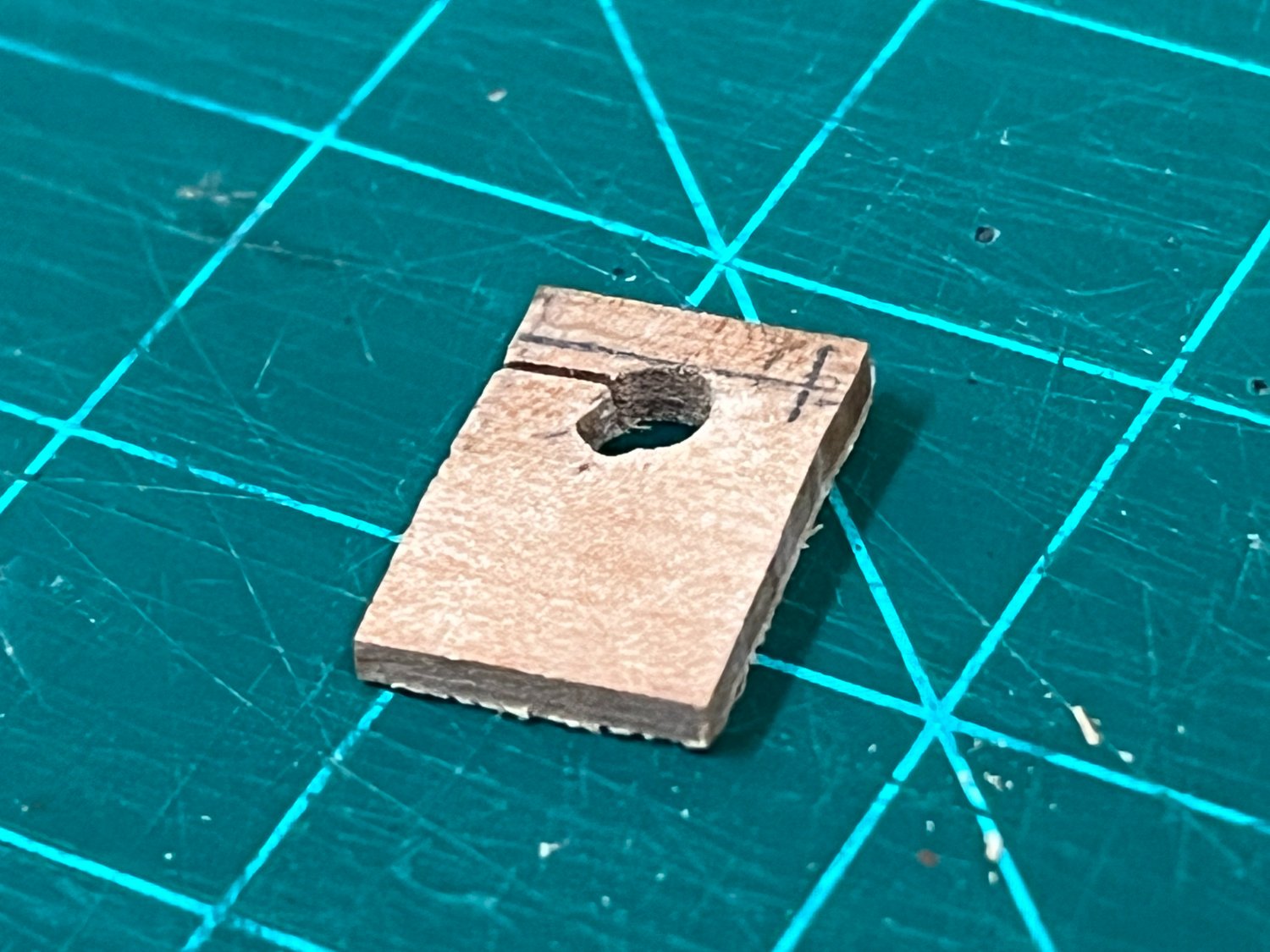
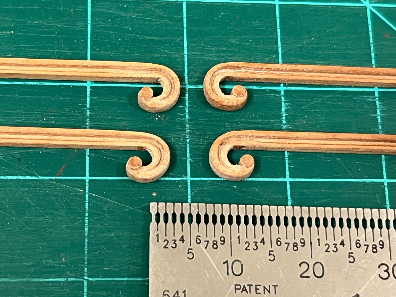
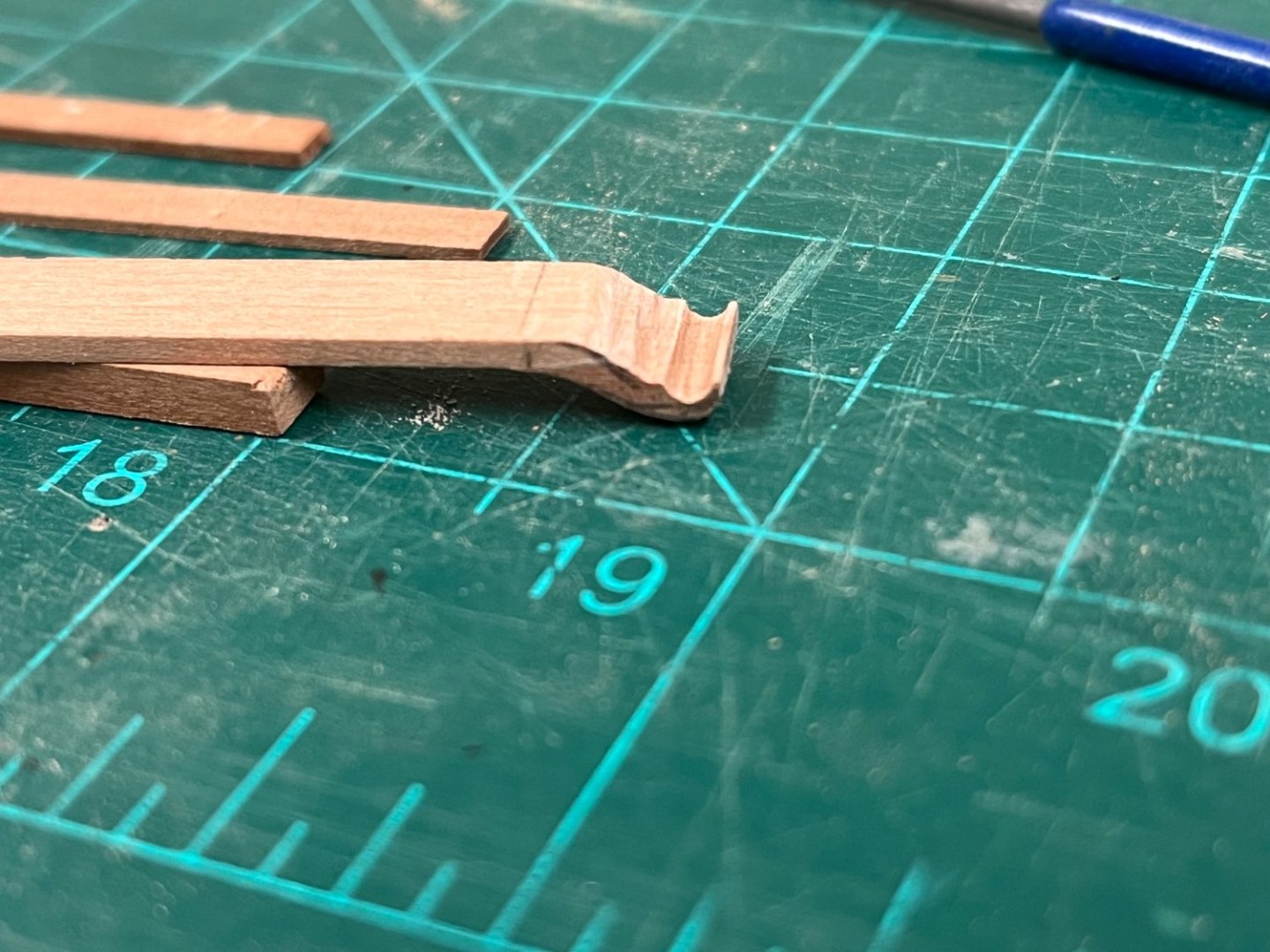
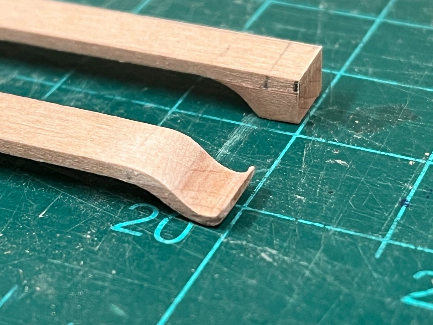
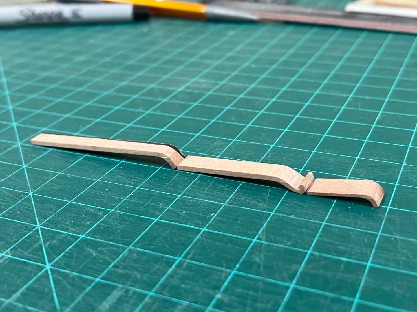
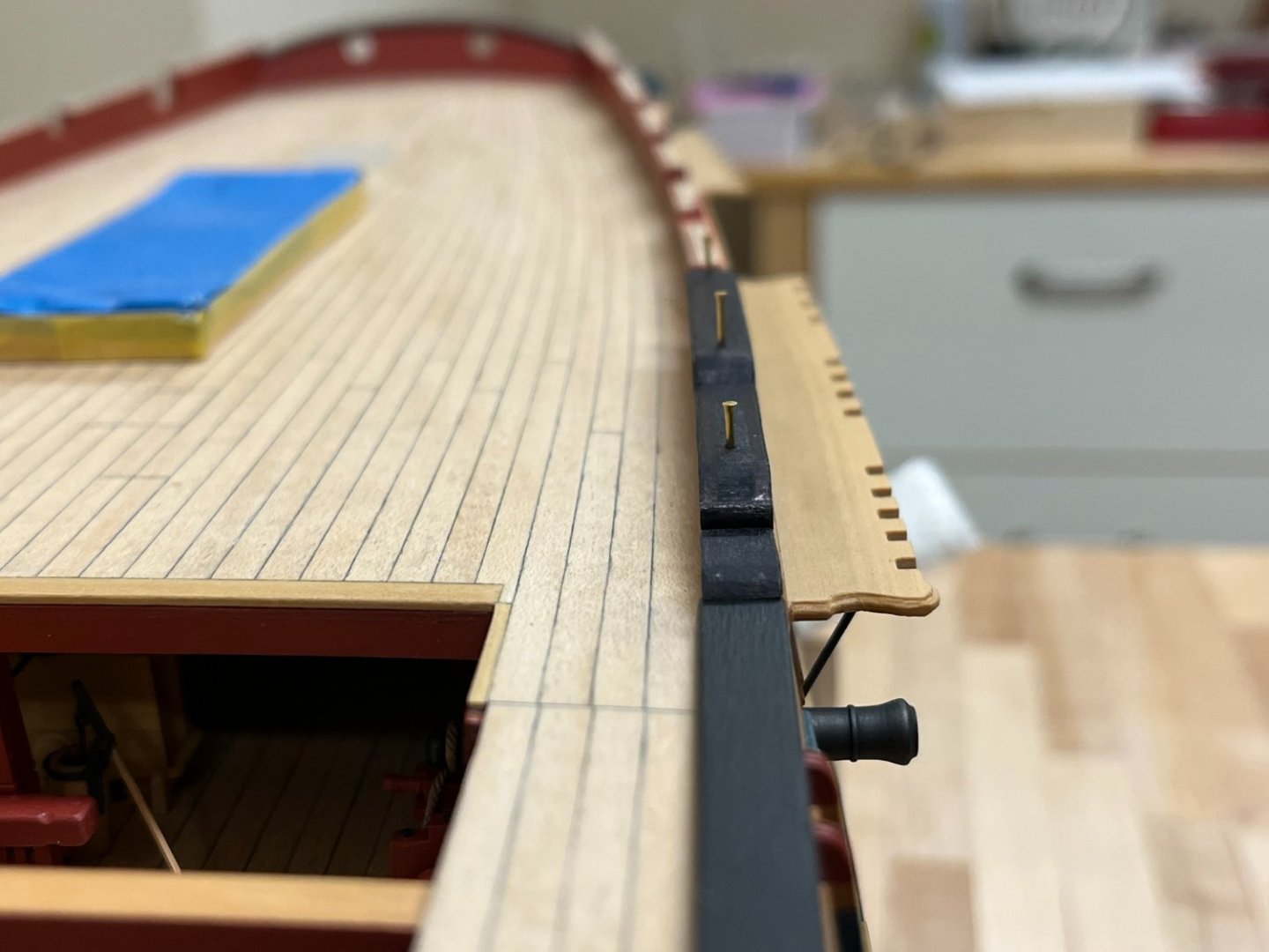
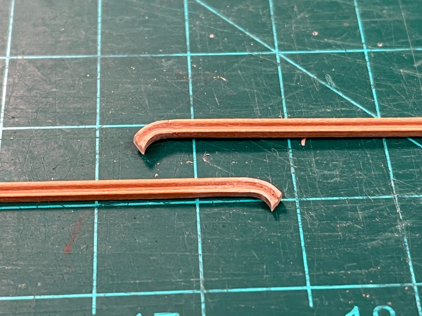
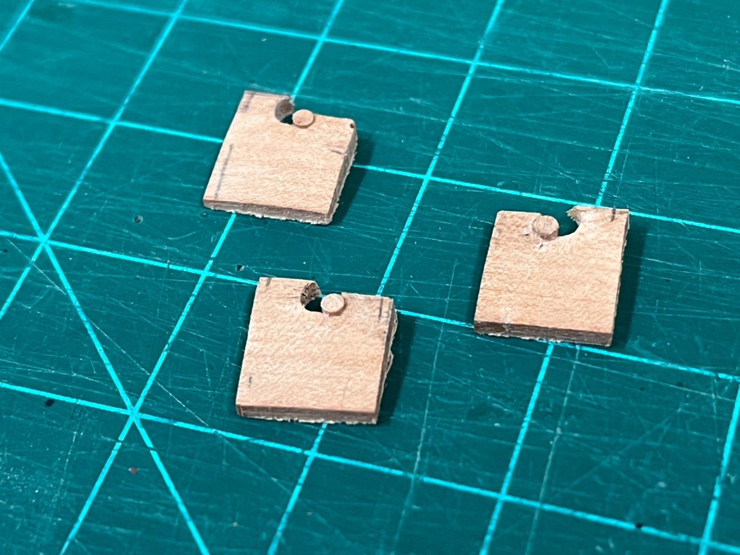
Hancing pieces and volutes.... I'm a little embarrassed that it has been so long that I've been away, somewhat from the shipyard but also this wonderful site. With the weather starting to turn and a bit more available time it seemed a good time to get back into things and try to pick up from a point that I left a little disheartened so many months ago. To be able to move forward, I had to come up with a solution for the hancing pieces which should then really allow much of the final hull form to be finalised. The problem I faced stemmed from the fact that I had to come up with a hancing piece volute 6mm high (per NMM plans) to transition the upper rails into the waist, and following a profile already established for the other rails. Although these are not large details, they are features that to my eye need to be sufficiently elegant and accurate to avoid detracting from the lines of the hull. I tried many different approaches, but here is the one that worked best for me and provided a method of construction that allowed consistent results. I'll apologize in advance for quality of the photographs, I was so focused on the work and forgot to check the photo quality as I progressed. 2.2 mm holes were drilled using a pin vise into some 2mm pear wood (actually 1.5mm + 0.5mm pear laminated together cross grain because I didn't have any 2mm sheet stock), this matches the starting thickness used for the upper rails which started as 2x2mm square strip. (A 2.2mm hole was found through visual trial and error to introduce the gradual narrowing of the rail into the end of the volute). A 1.5mm diameter recess was then carefully made at the edge using a round needle file at 45deg to the bottom of the hole. Each 'blank' was then cut from the sheet, given a slight reduced profile using an exacto blade, and a thin cut made above the filed lobe (explanation below). Small sections of 1.5mm diameter pear dowel were then glued into the 1.5mm recess, so they very slightly protruded above the top of the block. Sufficient PVA glue was used to ensure that these were well bonded. Once dry, a the top of the blanks were gently cut back and carefully finished against a circular sander so that the top edge of the blank was tangential to the top of the 2.2mm drilled hole (the cut previously made above the recess allows this section to release easily as it will no longer be needed. A length of 2x2mm pear wood strip was scraped with the same molding profile as used previously in the build, but care taken to leave an untouched section toward the end. The volute blanks were then attached to the unfinished end of the scraped molding. PVA glue was used generously, and left to dry overnight to ensure a full strength bond. Once dry, the excess was then carefully cut away to give proportions pleasing to the eye (mine at least) and ensure that the final volute form would be 6mm high. The rough cut was then very carefully reduced to its final shape using various grades of sanding sticks. Once the final shape was achieved, a profile needed to be introduced to match, and transition as smoothly as possible from the molding strip into the curve of the volute. To do this I needed to create a second scraper profile at the very edge of a razor blade to work on the volute curve effectively (the scraper profile used previously for strip had been centered to give best control on straight strip). This was performed very slowly as catastrophic failure would be very easy! While it is true that it took multiple experiments to get this method down, it did work well and the four needed volutes were all first time efforts with no rework, and despite the many imperfections highlighted by the macro lens, the results to the naked eye exceeded my expectations. In position, the volutes will now allow final shaping of the hull profile. Onto the next challenges!


-
Very much enjoyed catching up on your progress David. If only progress could be as speedy as reading a build log. Great to see some of the techniques you're using, and I totally agree the carronades need some serious TLC, yours came out very nice.
-
Like many things, I believe it depends on the period and the nation in question. From what I understand, the iron T-plates gradually replaced the wooden knees as metalwork became more prevalent in late 18th century. Thanasis' post above shows the redundancy that seems to be in place by having both - which probably did occur during the transition, and seems to have been ubiquitous through the history of ships.
-
Awesome progress David...been 'away' and missed so much of your progress, probably overloaded your inbox with 'likes' 🙂
- 310 replies
-
- 3
-
-
- Diana
- Caldercraft
- (and 1 more)
-
This subject and kit are very intriguing Mike, will definitely be following along. There seem to be a multitude of molded plastic/resin (?) parts which I'm hoping the kit provides elements to further detail these.
- 58 replies
-
- 2
-
-
- Calypso
- Billing Boats
- (and 1 more)
-
Looking great. I have nothing to point to, but the red ochre 'waterline' looks awkwardly low on the hull. Curious what pointed you in the direction of doing it so low.
-
Its amazing how you have created the various 3D printed parts David. You're really showing how this kit can really be taken to the next level with these details, you have a really beautiful model coming together. I'd love to know how to do what you do 🙂
-
HMS Bounty by AdamA - 1:48
Beef Wellington replied to AdamA's topic in - Build logs for subjects built 1751 - 1800
Adam, very much enjoyed catching up on your log, I very much appreciate you showing how you approached the basic wood working of each piece for those of us not too familiar with basic techniques, you make it look simple! A beautiful model you have coming together here, very much want to follow along. -
Looking fantastic! BTW - you could honestly sell that ladder making jig, I would buy one!