


Beef Wellington
-
Posts
2,245 -
Joined
-
Last visited
Reputation Activity
-

 Beef Wellington reacted to drtrap in HMS Snake by drtrap - Caldercraft
Hi Jason
To my knowledge, to be able to put and finish the stays (main and preventer) I have to fix the bowsprit dowel in advance.
Am I wrong somewhere?
-
 Beef Wellington got a reaction from popeye the sailor in Trafalgar Class Submarine by Old Collingwood - FINISHED - Airfix - 1/350 - PLASTIC
Count me in on this OC from here in, interesting to see how this comes together and how you approach the painting. Nicely done so far.
-
 Beef Wellington got a reaction from DaveBaxt in HMS Jason by Beef Wellington - Caldercraft - 1:64 - Artois-class frigate modified from HMS Diana 1794
First off, thanks everyone for the likes and comments, my apologies for not responding sooner. I haven't been able to keep up with everyone else's builds as much as I would have liked.
Been tinkering with a number of items that I want to get a head start on hopefully avoid pitfalls later. I'm leaning toward getting as much work on the hull planned out or complete before the cannons get installed and the upper deck can go on - although that will still be a while because I needed a break from gun carriages.
Trimming the bow height:
Way back I'd mentioned that I took the approach to build the bows up higher than I would likely need to allow for the unforeseen. I have now shaped these to be much closer to where I think they will end up, less a little finishing. The bulwarks at the bow appear to be parallel to the whale, just like the rails, which was used as a guide. This was an exercise in reconciliation as of course various small (or not so small) errors have crept in along the way. This proved not too difficult, the only hiccup was found when dry fitting the deck, to ensure that the height of the bulwark is symmetrical on both sides, some shims were added to the top of some of the forward bulkheads. The error is unlikely to be in the kit cut bulkheads, but more likely a combination of small discrepancies in my positioning of the position of the whales, waterline etc. You can see in shots below the discrepancy in the height of the foremost gunport, this was a result of positioning the ports to be of equal height off the deck, which was clearly not fitted as well as it should have been. These add about .5-0.75 of height on the starboard side, but the very small 'twist that this will introduce will not be noticeable. The sheer rail at the bow has also been added.
Headworks:
Have been doing a lot of thinking about how to approach the headworks, clearly a rather challenging area. Frankly, the kit supplied parts are a little disappointing being rather grainy and splintery, with some questionable dimensions. The main rail seemed to be the place to start, and after a lot of experimentation decided to build this and the false rail together rather than in separate pieces - mainly because it seems sturdier, and less challenging as the false rail is rather lengthy and thin at this scale. The main rails were cut from 2mm castello, and a profile introduced using a scraper to simulate the various features of the genuine article. Curved, tapering shapes have to be the hardest to get right, especially with fine details and there were many time consuming rejects which painfully got me up the learning curve until I was happy. The AOTS side elevations were scanned and manipulated digitally to correct for the angle to get the appropriate shape. Caution! I think the placement of the slot for the boomkin is not shown correctly on the AOTS side profile, I adjusted this looking at contemporary models - the revised position matches closely with the kit part which does provide some comfort.
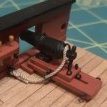
The false rail was cut from 0.6mm pear sheet and 2 were laminated together. The panel section of the false rail was cut out carefully to be shaped later by beveling the edges before replacing back in place. First photo below shows a little how these were built up, with the first successful but discarded prototype, and a main rail that failed scraping. Second photo below shows the kit supplied part next to the one of the scratched final articles. Ignoring the quality of the wood (and to be fair, I made no effort to clean up the supplied parts), the AOTS plans suggest a subtly different profile curve, and a thicker main rail which looks too thin on the kit part. The head of the main rail was deliberately cut a little longer to allow final shaping once these are finally installed.
These were then positioned with the head of the main rail vertical in both head on and side elevations. It was found that these were quite easy to keep in place using mini modeling clothes pins (scale replicas of the actual clothes pins used in actual ship construction ). Posting a lot of photos because I would really appreciate comments and suggestions from those more experienced with this to help me avoid fatal errors!
Finally, to confirm the layout of the boomkin slot, a copy was copied and scaled from the AOTS diagram. This shows the tight proximity of the boomkin and seat of ease. The triangular gap at the rear of the grating behind the false rail screen is where I believe there should be another seat of ease.
Again - I'm fumbling my way through this following the excellent TFFM book, so please do not be shy to point out errors and mistakes!
-
 Beef Wellington got a reaction from shipcarpenter in HMS Jason by Beef Wellington - Caldercraft - 1:64 - Artois-class frigate modified from HMS Diana 1794
First off, thanks everyone for the likes and comments, my apologies for not responding sooner. I haven't been able to keep up with everyone else's builds as much as I would have liked.
Been tinkering with a number of items that I want to get a head start on hopefully avoid pitfalls later. I'm leaning toward getting as much work on the hull planned out or complete before the cannons get installed and the upper deck can go on - although that will still be a while because I needed a break from gun carriages.
Trimming the bow height:
Way back I'd mentioned that I took the approach to build the bows up higher than I would likely need to allow for the unforeseen. I have now shaped these to be much closer to where I think they will end up, less a little finishing. The bulwarks at the bow appear to be parallel to the whale, just like the rails, which was used as a guide. This was an exercise in reconciliation as of course various small (or not so small) errors have crept in along the way. This proved not too difficult, the only hiccup was found when dry fitting the deck, to ensure that the height of the bulwark is symmetrical on both sides, some shims were added to the top of some of the forward bulkheads. The error is unlikely to be in the kit cut bulkheads, but more likely a combination of small discrepancies in my positioning of the position of the whales, waterline etc. You can see in shots below the discrepancy in the height of the foremost gunport, this was a result of positioning the ports to be of equal height off the deck, which was clearly not fitted as well as it should have been. These add about .5-0.75 of height on the starboard side, but the very small 'twist that this will introduce will not be noticeable. The sheer rail at the bow has also been added.
Headworks:
Have been doing a lot of thinking about how to approach the headworks, clearly a rather challenging area. Frankly, the kit supplied parts are a little disappointing being rather grainy and splintery, with some questionable dimensions. The main rail seemed to be the place to start, and after a lot of experimentation decided to build this and the false rail together rather than in separate pieces - mainly because it seems sturdier, and less challenging as the false rail is rather lengthy and thin at this scale. The main rails were cut from 2mm castello, and a profile introduced using a scraper to simulate the various features of the genuine article. Curved, tapering shapes have to be the hardest to get right, especially with fine details and there were many time consuming rejects which painfully got me up the learning curve until I was happy. The AOTS side elevations were scanned and manipulated digitally to correct for the angle to get the appropriate shape. Caution! I think the placement of the slot for the boomkin is not shown correctly on the AOTS side profile, I adjusted this looking at contemporary models - the revised position matches closely with the kit part which does provide some comfort.
The false rail was cut from 0.6mm pear sheet and 2 were laminated together. The panel section of the false rail was cut out carefully to be shaped later by beveling the edges before replacing back in place. First photo below shows a little how these were built up, with the first successful but discarded prototype, and a main rail that failed scraping. Second photo below shows the kit supplied part next to the one of the scratched final articles. Ignoring the quality of the wood (and to be fair, I made no effort to clean up the supplied parts), the AOTS plans suggest a subtly different profile curve, and a thicker main rail which looks too thin on the kit part. The head of the main rail was deliberately cut a little longer to allow final shaping once these are finally installed.
These were then positioned with the head of the main rail vertical in both head on and side elevations. It was found that these were quite easy to keep in place using mini modeling clothes pins (scale replicas of the actual clothes pins used in actual ship construction ). Posting a lot of photos because I would really appreciate comments and suggestions from those more experienced with this to help me avoid fatal errors!
Finally, to confirm the layout of the boomkin slot, a copy was copied and scaled from the AOTS diagram. This shows the tight proximity of the boomkin and seat of ease. The triangular gap at the rear of the grating behind the false rail screen is where I believe there should be another seat of ease.
Again - I'm fumbling my way through this following the excellent TFFM book, so please do not be shy to point out errors and mistakes!
-
 Beef Wellington got a reaction from Piet in Trafalgar Class Submarine by Old Collingwood - FINISHED - Airfix - 1/350 - PLASTIC
Count me in on this OC from here in, interesting to see how this comes together and how you approach the painting. Nicely done so far.
-
 Beef Wellington got a reaction from Mirabell61 in HMS Jason by Beef Wellington - Caldercraft - 1:64 - Artois-class frigate modified from HMS Diana 1794
First off, thanks everyone for the likes and comments, my apologies for not responding sooner. I haven't been able to keep up with everyone else's builds as much as I would have liked.
Been tinkering with a number of items that I want to get a head start on hopefully avoid pitfalls later. I'm leaning toward getting as much work on the hull planned out or complete before the cannons get installed and the upper deck can go on - although that will still be a while because I needed a break from gun carriages.
Trimming the bow height:
Way back I'd mentioned that I took the approach to build the bows up higher than I would likely need to allow for the unforeseen. I have now shaped these to be much closer to where I think they will end up, less a little finishing. The bulwarks at the bow appear to be parallel to the whale, just like the rails, which was used as a guide. This was an exercise in reconciliation as of course various small (or not so small) errors have crept in along the way. This proved not too difficult, the only hiccup was found when dry fitting the deck, to ensure that the height of the bulwark is symmetrical on both sides, some shims were added to the top of some of the forward bulkheads. The error is unlikely to be in the kit cut bulkheads, but more likely a combination of small discrepancies in my positioning of the position of the whales, waterline etc. You can see in shots below the discrepancy in the height of the foremost gunport, this was a result of positioning the ports to be of equal height off the deck, which was clearly not fitted as well as it should have been. These add about .5-0.75 of height on the starboard side, but the very small 'twist that this will introduce will not be noticeable. The sheer rail at the bow has also been added.
Headworks:
Have been doing a lot of thinking about how to approach the headworks, clearly a rather challenging area. Frankly, the kit supplied parts are a little disappointing being rather grainy and splintery, with some questionable dimensions. The main rail seemed to be the place to start, and after a lot of experimentation decided to build this and the false rail together rather than in separate pieces - mainly because it seems sturdier, and less challenging as the false rail is rather lengthy and thin at this scale. The main rails were cut from 2mm castello, and a profile introduced using a scraper to simulate the various features of the genuine article. Curved, tapering shapes have to be the hardest to get right, especially with fine details and there were many time consuming rejects which painfully got me up the learning curve until I was happy. The AOTS side elevations were scanned and manipulated digitally to correct for the angle to get the appropriate shape. Caution! I think the placement of the slot for the boomkin is not shown correctly on the AOTS side profile, I adjusted this looking at contemporary models - the revised position matches closely with the kit part which does provide some comfort.
The false rail was cut from 0.6mm pear sheet and 2 were laminated together. The panel section of the false rail was cut out carefully to be shaped later by beveling the edges before replacing back in place. First photo below shows a little how these were built up, with the first successful but discarded prototype, and a main rail that failed scraping. Second photo below shows the kit supplied part next to the one of the scratched final articles. Ignoring the quality of the wood (and to be fair, I made no effort to clean up the supplied parts), the AOTS plans suggest a subtly different profile curve, and a thicker main rail which looks too thin on the kit part. The head of the main rail was deliberately cut a little longer to allow final shaping once these are finally installed.
These were then positioned with the head of the main rail vertical in both head on and side elevations. It was found that these were quite easy to keep in place using mini modeling clothes pins (scale replicas of the actual clothes pins used in actual ship construction ). Posting a lot of photos because I would really appreciate comments and suggestions from those more experienced with this to help me avoid fatal errors!
Finally, to confirm the layout of the boomkin slot, a copy was copied and scaled from the AOTS diagram. This shows the tight proximity of the boomkin and seat of ease. The triangular gap at the rear of the grating behind the false rail screen is where I believe there should be another seat of ease.
Again - I'm fumbling my way through this following the excellent TFFM book, so please do not be shy to point out errors and mistakes!
-
 Beef Wellington got a reaction from cog in Trafalgar Class Submarine by Old Collingwood - FINISHED - Airfix - 1/350 - PLASTIC
Count me in on this OC from here in, interesting to see how this comes together and how you approach the painting. Nicely done so far.
-
Beef Wellington reacted to Old Collingwood in Trafalgar Class Submarine by Old Collingwood - FINISHED - Airfix - 1/350 - PLASTIC
I got a bit more time on the bench - these subs have acustic tiles glued onto thier dark grey/black hull, so on many areas the tiles are either missing or not placed, two of these areas are both sides a kind of zig zag pattern that shows the hull color, also down the center line there is a flat black anti-slip walkway.
So I have painted these areas with the masked areas as required.
Just the two pics.
OC.
-
 Beef Wellington got a reaction from Old Collingwood in Trafalgar Class Submarine by Old Collingwood - FINISHED - Airfix - 1/350 - PLASTIC
Count me in on this OC from here in, interesting to see how this comes together and how you approach the painting. Nicely done so far.
-
 Beef Wellington got a reaction from Canute in Trafalgar Class Submarine by Old Collingwood - FINISHED - Airfix - 1/350 - PLASTIC
Count me in on this OC from here in, interesting to see how this comes together and how you approach the painting. Nicely done so far.
-
 Beef Wellington got a reaction from yvesvidal in HMS Jason by Beef Wellington - Caldercraft - 1:64 - Artois-class frigate modified from HMS Diana 1794
First off, thanks everyone for the likes and comments, my apologies for not responding sooner. I haven't been able to keep up with everyone else's builds as much as I would have liked.
Been tinkering with a number of items that I want to get a head start on hopefully avoid pitfalls later. I'm leaning toward getting as much work on the hull planned out or complete before the cannons get installed and the upper deck can go on - although that will still be a while because I needed a break from gun carriages.
Trimming the bow height:
Way back I'd mentioned that I took the approach to build the bows up higher than I would likely need to allow for the unforeseen. I have now shaped these to be much closer to where I think they will end up, less a little finishing. The bulwarks at the bow appear to be parallel to the whale, just like the rails, which was used as a guide. This was an exercise in reconciliation as of course various small (or not so small) errors have crept in along the way. This proved not too difficult, the only hiccup was found when dry fitting the deck, to ensure that the height of the bulwark is symmetrical on both sides, some shims were added to the top of some of the forward bulkheads. The error is unlikely to be in the kit cut bulkheads, but more likely a combination of small discrepancies in my positioning of the position of the whales, waterline etc. You can see in shots below the discrepancy in the height of the foremost gunport, this was a result of positioning the ports to be of equal height off the deck, which was clearly not fitted as well as it should have been. These add about .5-0.75 of height on the starboard side, but the very small 'twist that this will introduce will not be noticeable. The sheer rail at the bow has also been added.
Headworks:
Have been doing a lot of thinking about how to approach the headworks, clearly a rather challenging area. Frankly, the kit supplied parts are a little disappointing being rather grainy and splintery, with some questionable dimensions. The main rail seemed to be the place to start, and after a lot of experimentation decided to build this and the false rail together rather than in separate pieces - mainly because it seems sturdier, and less challenging as the false rail is rather lengthy and thin at this scale. The main rails were cut from 2mm castello, and a profile introduced using a scraper to simulate the various features of the genuine article. Curved, tapering shapes have to be the hardest to get right, especially with fine details and there were many time consuming rejects which painfully got me up the learning curve until I was happy. The AOTS side elevations were scanned and manipulated digitally to correct for the angle to get the appropriate shape. Caution! I think the placement of the slot for the boomkin is not shown correctly on the AOTS side profile, I adjusted this looking at contemporary models - the revised position matches closely with the kit part which does provide some comfort.
The false rail was cut from 0.6mm pear sheet and 2 were laminated together. The panel section of the false rail was cut out carefully to be shaped later by beveling the edges before replacing back in place. First photo below shows a little how these were built up, with the first successful but discarded prototype, and a main rail that failed scraping. Second photo below shows the kit supplied part next to the one of the scratched final articles. Ignoring the quality of the wood (and to be fair, I made no effort to clean up the supplied parts), the AOTS plans suggest a subtly different profile curve, and a thicker main rail which looks too thin on the kit part. The head of the main rail was deliberately cut a little longer to allow final shaping once these are finally installed.
These were then positioned with the head of the main rail vertical in both head on and side elevations. It was found that these were quite easy to keep in place using mini modeling clothes pins (scale replicas of the actual clothes pins used in actual ship construction ). Posting a lot of photos because I would really appreciate comments and suggestions from those more experienced with this to help me avoid fatal errors!
Finally, to confirm the layout of the boomkin slot, a copy was copied and scaled from the AOTS diagram. This shows the tight proximity of the boomkin and seat of ease. The triangular gap at the rear of the grating behind the false rail screen is where I believe there should be another seat of ease.
Again - I'm fumbling my way through this following the excellent TFFM book, so please do not be shy to point out errors and mistakes!
-
 Beef Wellington got a reaction from Gahm in HMS Jason by Beef Wellington - Caldercraft - 1:64 - Artois-class frigate modified from HMS Diana 1794
First off, thanks everyone for the likes and comments, my apologies for not responding sooner. I haven't been able to keep up with everyone else's builds as much as I would have liked.
Been tinkering with a number of items that I want to get a head start on hopefully avoid pitfalls later. I'm leaning toward getting as much work on the hull planned out or complete before the cannons get installed and the upper deck can go on - although that will still be a while because I needed a break from gun carriages.
Trimming the bow height:
Way back I'd mentioned that I took the approach to build the bows up higher than I would likely need to allow for the unforeseen. I have now shaped these to be much closer to where I think they will end up, less a little finishing. The bulwarks at the bow appear to be parallel to the whale, just like the rails, which was used as a guide. This was an exercise in reconciliation as of course various small (or not so small) errors have crept in along the way. This proved not too difficult, the only hiccup was found when dry fitting the deck, to ensure that the height of the bulwark is symmetrical on both sides, some shims were added to the top of some of the forward bulkheads. The error is unlikely to be in the kit cut bulkheads, but more likely a combination of small discrepancies in my positioning of the position of the whales, waterline etc. You can see in shots below the discrepancy in the height of the foremost gunport, this was a result of positioning the ports to be of equal height off the deck, which was clearly not fitted as well as it should have been. These add about .5-0.75 of height on the starboard side, but the very small 'twist that this will introduce will not be noticeable. The sheer rail at the bow has also been added.
Headworks:
Have been doing a lot of thinking about how to approach the headworks, clearly a rather challenging area. Frankly, the kit supplied parts are a little disappointing being rather grainy and splintery, with some questionable dimensions. The main rail seemed to be the place to start, and after a lot of experimentation decided to build this and the false rail together rather than in separate pieces - mainly because it seems sturdier, and less challenging as the false rail is rather lengthy and thin at this scale. The main rails were cut from 2mm castello, and a profile introduced using a scraper to simulate the various features of the genuine article. Curved, tapering shapes have to be the hardest to get right, especially with fine details and there were many time consuming rejects which painfully got me up the learning curve until I was happy. The AOTS side elevations were scanned and manipulated digitally to correct for the angle to get the appropriate shape. Caution! I think the placement of the slot for the boomkin is not shown correctly on the AOTS side profile, I adjusted this looking at contemporary models - the revised position matches closely with the kit part which does provide some comfort.
The false rail was cut from 0.6mm pear sheet and 2 were laminated together. The panel section of the false rail was cut out carefully to be shaped later by beveling the edges before replacing back in place. First photo below shows a little how these were built up, with the first successful but discarded prototype, and a main rail that failed scraping. Second photo below shows the kit supplied part next to the one of the scratched final articles. Ignoring the quality of the wood (and to be fair, I made no effort to clean up the supplied parts), the AOTS plans suggest a subtly different profile curve, and a thicker main rail which looks too thin on the kit part. The head of the main rail was deliberately cut a little longer to allow final shaping once these are finally installed.
These were then positioned with the head of the main rail vertical in both head on and side elevations. It was found that these were quite easy to keep in place using mini modeling clothes pins (scale replicas of the actual clothes pins used in actual ship construction ). Posting a lot of photos because I would really appreciate comments and suggestions from those more experienced with this to help me avoid fatal errors!
Finally, to confirm the layout of the boomkin slot, a copy was copied and scaled from the AOTS diagram. This shows the tight proximity of the boomkin and seat of ease. The triangular gap at the rear of the grating behind the false rail screen is where I believe there should be another seat of ease.
Again - I'm fumbling my way through this following the excellent TFFM book, so please do not be shy to point out errors and mistakes!
-
 Beef Wellington got a reaction from robdurant in HMS Jason by Beef Wellington - Caldercraft - 1:64 - Artois-class frigate modified from HMS Diana 1794
First off, thanks everyone for the likes and comments, my apologies for not responding sooner. I haven't been able to keep up with everyone else's builds as much as I would have liked.
Been tinkering with a number of items that I want to get a head start on hopefully avoid pitfalls later. I'm leaning toward getting as much work on the hull planned out or complete before the cannons get installed and the upper deck can go on - although that will still be a while because I needed a break from gun carriages.
Trimming the bow height:
Way back I'd mentioned that I took the approach to build the bows up higher than I would likely need to allow for the unforeseen. I have now shaped these to be much closer to where I think they will end up, less a little finishing. The bulwarks at the bow appear to be parallel to the whale, just like the rails, which was used as a guide. This was an exercise in reconciliation as of course various small (or not so small) errors have crept in along the way. This proved not too difficult, the only hiccup was found when dry fitting the deck, to ensure that the height of the bulwark is symmetrical on both sides, some shims were added to the top of some of the forward bulkheads. The error is unlikely to be in the kit cut bulkheads, but more likely a combination of small discrepancies in my positioning of the position of the whales, waterline etc. You can see in shots below the discrepancy in the height of the foremost gunport, this was a result of positioning the ports to be of equal height off the deck, which was clearly not fitted as well as it should have been. These add about .5-0.75 of height on the starboard side, but the very small 'twist that this will introduce will not be noticeable. The sheer rail at the bow has also been added.
Headworks:
Have been doing a lot of thinking about how to approach the headworks, clearly a rather challenging area. Frankly, the kit supplied parts are a little disappointing being rather grainy and splintery, with some questionable dimensions. The main rail seemed to be the place to start, and after a lot of experimentation decided to build this and the false rail together rather than in separate pieces - mainly because it seems sturdier, and less challenging as the false rail is rather lengthy and thin at this scale. The main rails were cut from 2mm castello, and a profile introduced using a scraper to simulate the various features of the genuine article. Curved, tapering shapes have to be the hardest to get right, especially with fine details and there were many time consuming rejects which painfully got me up the learning curve until I was happy. The AOTS side elevations were scanned and manipulated digitally to correct for the angle to get the appropriate shape. Caution! I think the placement of the slot for the boomkin is not shown correctly on the AOTS side profile, I adjusted this looking at contemporary models - the revised position matches closely with the kit part which does provide some comfort.
The false rail was cut from 0.6mm pear sheet and 2 were laminated together. The panel section of the false rail was cut out carefully to be shaped later by beveling the edges before replacing back in place. First photo below shows a little how these were built up, with the first successful but discarded prototype, and a main rail that failed scraping. Second photo below shows the kit supplied part next to the one of the scratched final articles. Ignoring the quality of the wood (and to be fair, I made no effort to clean up the supplied parts), the AOTS plans suggest a subtly different profile curve, and a thicker main rail which looks too thin on the kit part. The head of the main rail was deliberately cut a little longer to allow final shaping once these are finally installed.
These were then positioned with the head of the main rail vertical in both head on and side elevations. It was found that these were quite easy to keep in place using mini modeling clothes pins (scale replicas of the actual clothes pins used in actual ship construction ). Posting a lot of photos because I would really appreciate comments and suggestions from those more experienced with this to help me avoid fatal errors!
Finally, to confirm the layout of the boomkin slot, a copy was copied and scaled from the AOTS diagram. This shows the tight proximity of the boomkin and seat of ease. The triangular gap at the rear of the grating behind the false rail screen is where I believe there should be another seat of ease.
Again - I'm fumbling my way through this following the excellent TFFM book, so please do not be shy to point out errors and mistakes!
-
 Beef Wellington got a reaction from Blue Ensign in HMS Jason by Beef Wellington - Caldercraft - 1:64 - Artois-class frigate modified from HMS Diana 1794
First off, thanks everyone for the likes and comments, my apologies for not responding sooner. I haven't been able to keep up with everyone else's builds as much as I would have liked.
Been tinkering with a number of items that I want to get a head start on hopefully avoid pitfalls later. I'm leaning toward getting as much work on the hull planned out or complete before the cannons get installed and the upper deck can go on - although that will still be a while because I needed a break from gun carriages.
Trimming the bow height:
Way back I'd mentioned that I took the approach to build the bows up higher than I would likely need to allow for the unforeseen. I have now shaped these to be much closer to where I think they will end up, less a little finishing. The bulwarks at the bow appear to be parallel to the whale, just like the rails, which was used as a guide. This was an exercise in reconciliation as of course various small (or not so small) errors have crept in along the way. This proved not too difficult, the only hiccup was found when dry fitting the deck, to ensure that the height of the bulwark is symmetrical on both sides, some shims were added to the top of some of the forward bulkheads. The error is unlikely to be in the kit cut bulkheads, but more likely a combination of small discrepancies in my positioning of the position of the whales, waterline etc. You can see in shots below the discrepancy in the height of the foremost gunport, this was a result of positioning the ports to be of equal height off the deck, which was clearly not fitted as well as it should have been. These add about .5-0.75 of height on the starboard side, but the very small 'twist that this will introduce will not be noticeable. The sheer rail at the bow has also been added.
Headworks:
Have been doing a lot of thinking about how to approach the headworks, clearly a rather challenging area. Frankly, the kit supplied parts are a little disappointing being rather grainy and splintery, with some questionable dimensions. The main rail seemed to be the place to start, and after a lot of experimentation decided to build this and the false rail together rather than in separate pieces - mainly because it seems sturdier, and less challenging as the false rail is rather lengthy and thin at this scale. The main rails were cut from 2mm castello, and a profile introduced using a scraper to simulate the various features of the genuine article. Curved, tapering shapes have to be the hardest to get right, especially with fine details and there were many time consuming rejects which painfully got me up the learning curve until I was happy. The AOTS side elevations were scanned and manipulated digitally to correct for the angle to get the appropriate shape. Caution! I think the placement of the slot for the boomkin is not shown correctly on the AOTS side profile, I adjusted this looking at contemporary models - the revised position matches closely with the kit part which does provide some comfort.
The false rail was cut from 0.6mm pear sheet and 2 were laminated together. The panel section of the false rail was cut out carefully to be shaped later by beveling the edges before replacing back in place. First photo below shows a little how these were built up, with the first successful but discarded prototype, and a main rail that failed scraping. Second photo below shows the kit supplied part next to the one of the scratched final articles. Ignoring the quality of the wood (and to be fair, I made no effort to clean up the supplied parts), the AOTS plans suggest a subtly different profile curve, and a thicker main rail which looks too thin on the kit part. The head of the main rail was deliberately cut a little longer to allow final shaping once these are finally installed.
These were then positioned with the head of the main rail vertical in both head on and side elevations. It was found that these were quite easy to keep in place using mini modeling clothes pins (scale replicas of the actual clothes pins used in actual ship construction ). Posting a lot of photos because I would really appreciate comments and suggestions from those more experienced with this to help me avoid fatal errors!
Finally, to confirm the layout of the boomkin slot, a copy was copied and scaled from the AOTS diagram. This shows the tight proximity of the boomkin and seat of ease. The triangular gap at the rear of the grating behind the false rail screen is where I believe there should be another seat of ease.
Again - I'm fumbling my way through this following the excellent TFFM book, so please do not be shy to point out errors and mistakes!
-
 Beef Wellington got a reaction from toms10 in HMS Jason by Beef Wellington - Caldercraft - 1:64 - Artois-class frigate modified from HMS Diana 1794
First off, thanks everyone for the likes and comments, my apologies for not responding sooner. I haven't been able to keep up with everyone else's builds as much as I would have liked.
Been tinkering with a number of items that I want to get a head start on hopefully avoid pitfalls later. I'm leaning toward getting as much work on the hull planned out or complete before the cannons get installed and the upper deck can go on - although that will still be a while because I needed a break from gun carriages.
Trimming the bow height:
Way back I'd mentioned that I took the approach to build the bows up higher than I would likely need to allow for the unforeseen. I have now shaped these to be much closer to where I think they will end up, less a little finishing. The bulwarks at the bow appear to be parallel to the whale, just like the rails, which was used as a guide. This was an exercise in reconciliation as of course various small (or not so small) errors have crept in along the way. This proved not too difficult, the only hiccup was found when dry fitting the deck, to ensure that the height of the bulwark is symmetrical on both sides, some shims were added to the top of some of the forward bulkheads. The error is unlikely to be in the kit cut bulkheads, but more likely a combination of small discrepancies in my positioning of the position of the whales, waterline etc. You can see in shots below the discrepancy in the height of the foremost gunport, this was a result of positioning the ports to be of equal height off the deck, which was clearly not fitted as well as it should have been. These add about .5-0.75 of height on the starboard side, but the very small 'twist that this will introduce will not be noticeable. The sheer rail at the bow has also been added.
Headworks:
Have been doing a lot of thinking about how to approach the headworks, clearly a rather challenging area. Frankly, the kit supplied parts are a little disappointing being rather grainy and splintery, with some questionable dimensions. The main rail seemed to be the place to start, and after a lot of experimentation decided to build this and the false rail together rather than in separate pieces - mainly because it seems sturdier, and less challenging as the false rail is rather lengthy and thin at this scale. The main rails were cut from 2mm castello, and a profile introduced using a scraper to simulate the various features of the genuine article. Curved, tapering shapes have to be the hardest to get right, especially with fine details and there were many time consuming rejects which painfully got me up the learning curve until I was happy. The AOTS side elevations were scanned and manipulated digitally to correct for the angle to get the appropriate shape. Caution! I think the placement of the slot for the boomkin is not shown correctly on the AOTS side profile, I adjusted this looking at contemporary models - the revised position matches closely with the kit part which does provide some comfort.
The false rail was cut from 0.6mm pear sheet and 2 were laminated together. The panel section of the false rail was cut out carefully to be shaped later by beveling the edges before replacing back in place. First photo below shows a little how these were built up, with the first successful but discarded prototype, and a main rail that failed scraping. Second photo below shows the kit supplied part next to the one of the scratched final articles. Ignoring the quality of the wood (and to be fair, I made no effort to clean up the supplied parts), the AOTS plans suggest a subtly different profile curve, and a thicker main rail which looks too thin on the kit part. The head of the main rail was deliberately cut a little longer to allow final shaping once these are finally installed.
These were then positioned with the head of the main rail vertical in both head on and side elevations. It was found that these were quite easy to keep in place using mini modeling clothes pins (scale replicas of the actual clothes pins used in actual ship construction ). Posting a lot of photos because I would really appreciate comments and suggestions from those more experienced with this to help me avoid fatal errors!
Finally, to confirm the layout of the boomkin slot, a copy was copied and scaled from the AOTS diagram. This shows the tight proximity of the boomkin and seat of ease. The triangular gap at the rear of the grating behind the false rail screen is where I believe there should be another seat of ease.
Again - I'm fumbling my way through this following the excellent TFFM book, so please do not be shy to point out errors and mistakes!
-
 Beef Wellington got a reaction from jwvolz in HMS Jason by Beef Wellington - Caldercraft - 1:64 - Artois-class frigate modified from HMS Diana 1794
First off, thanks everyone for the likes and comments, my apologies for not responding sooner. I haven't been able to keep up with everyone else's builds as much as I would have liked.
Been tinkering with a number of items that I want to get a head start on hopefully avoid pitfalls later. I'm leaning toward getting as much work on the hull planned out or complete before the cannons get installed and the upper deck can go on - although that will still be a while because I needed a break from gun carriages.
Trimming the bow height:
Way back I'd mentioned that I took the approach to build the bows up higher than I would likely need to allow for the unforeseen. I have now shaped these to be much closer to where I think they will end up, less a little finishing. The bulwarks at the bow appear to be parallel to the whale, just like the rails, which was used as a guide. This was an exercise in reconciliation as of course various small (or not so small) errors have crept in along the way. This proved not too difficult, the only hiccup was found when dry fitting the deck, to ensure that the height of the bulwark is symmetrical on both sides, some shims were added to the top of some of the forward bulkheads. The error is unlikely to be in the kit cut bulkheads, but more likely a combination of small discrepancies in my positioning of the position of the whales, waterline etc. You can see in shots below the discrepancy in the height of the foremost gunport, this was a result of positioning the ports to be of equal height off the deck, which was clearly not fitted as well as it should have been. These add about .5-0.75 of height on the starboard side, but the very small 'twist that this will introduce will not be noticeable. The sheer rail at the bow has also been added.
Headworks:
Have been doing a lot of thinking about how to approach the headworks, clearly a rather challenging area. Frankly, the kit supplied parts are a little disappointing being rather grainy and splintery, with some questionable dimensions. The main rail seemed to be the place to start, and after a lot of experimentation decided to build this and the false rail together rather than in separate pieces - mainly because it seems sturdier, and less challenging as the false rail is rather lengthy and thin at this scale. The main rails were cut from 2mm castello, and a profile introduced using a scraper to simulate the various features of the genuine article. Curved, tapering shapes have to be the hardest to get right, especially with fine details and there were many time consuming rejects which painfully got me up the learning curve until I was happy. The AOTS side elevations were scanned and manipulated digitally to correct for the angle to get the appropriate shape. Caution! I think the placement of the slot for the boomkin is not shown correctly on the AOTS side profile, I adjusted this looking at contemporary models - the revised position matches closely with the kit part which does provide some comfort.
The false rail was cut from 0.6mm pear sheet and 2 were laminated together. The panel section of the false rail was cut out carefully to be shaped later by beveling the edges before replacing back in place. First photo below shows a little how these were built up, with the first successful but discarded prototype, and a main rail that failed scraping. Second photo below shows the kit supplied part next to the one of the scratched final articles. Ignoring the quality of the wood (and to be fair, I made no effort to clean up the supplied parts), the AOTS plans suggest a subtly different profile curve, and a thicker main rail which looks too thin on the kit part. The head of the main rail was deliberately cut a little longer to allow final shaping once these are finally installed.
These were then positioned with the head of the main rail vertical in both head on and side elevations. It was found that these were quite easy to keep in place using mini modeling clothes pins (scale replicas of the actual clothes pins used in actual ship construction ). Posting a lot of photos because I would really appreciate comments and suggestions from those more experienced with this to help me avoid fatal errors!
Finally, to confirm the layout of the boomkin slot, a copy was copied and scaled from the AOTS diagram. This shows the tight proximity of the boomkin and seat of ease. The triangular gap at the rear of the grating behind the false rail screen is where I believe there should be another seat of ease.
Again - I'm fumbling my way through this following the excellent TFFM book, so please do not be shy to point out errors and mistakes!
-
 Beef Wellington got a reaction from Ferit in HMS Jason by Beef Wellington - Caldercraft - 1:64 - Artois-class frigate modified from HMS Diana 1794
First off, thanks everyone for the likes and comments, my apologies for not responding sooner. I haven't been able to keep up with everyone else's builds as much as I would have liked.
Been tinkering with a number of items that I want to get a head start on hopefully avoid pitfalls later. I'm leaning toward getting as much work on the hull planned out or complete before the cannons get installed and the upper deck can go on - although that will still be a while because I needed a break from gun carriages.
Trimming the bow height:
Way back I'd mentioned that I took the approach to build the bows up higher than I would likely need to allow for the unforeseen. I have now shaped these to be much closer to where I think they will end up, less a little finishing. The bulwarks at the bow appear to be parallel to the whale, just like the rails, which was used as a guide. This was an exercise in reconciliation as of course various small (or not so small) errors have crept in along the way. This proved not too difficult, the only hiccup was found when dry fitting the deck, to ensure that the height of the bulwark is symmetrical on both sides, some shims were added to the top of some of the forward bulkheads. The error is unlikely to be in the kit cut bulkheads, but more likely a combination of small discrepancies in my positioning of the position of the whales, waterline etc. You can see in shots below the discrepancy in the height of the foremost gunport, this was a result of positioning the ports to be of equal height off the deck, which was clearly not fitted as well as it should have been. These add about .5-0.75 of height on the starboard side, but the very small 'twist that this will introduce will not be noticeable. The sheer rail at the bow has also been added.
Headworks:
Have been doing a lot of thinking about how to approach the headworks, clearly a rather challenging area. Frankly, the kit supplied parts are a little disappointing being rather grainy and splintery, with some questionable dimensions. The main rail seemed to be the place to start, and after a lot of experimentation decided to build this and the false rail together rather than in separate pieces - mainly because it seems sturdier, and less challenging as the false rail is rather lengthy and thin at this scale. The main rails were cut from 2mm castello, and a profile introduced using a scraper to simulate the various features of the genuine article. Curved, tapering shapes have to be the hardest to get right, especially with fine details and there were many time consuming rejects which painfully got me up the learning curve until I was happy. The AOTS side elevations were scanned and manipulated digitally to correct for the angle to get the appropriate shape. Caution! I think the placement of the slot for the boomkin is not shown correctly on the AOTS side profile, I adjusted this looking at contemporary models - the revised position matches closely with the kit part which does provide some comfort.
The false rail was cut from 0.6mm pear sheet and 2 were laminated together. The panel section of the false rail was cut out carefully to be shaped later by beveling the edges before replacing back in place. First photo below shows a little how these were built up, with the first successful but discarded prototype, and a main rail that failed scraping. Second photo below shows the kit supplied part next to the one of the scratched final articles. Ignoring the quality of the wood (and to be fair, I made no effort to clean up the supplied parts), the AOTS plans suggest a subtly different profile curve, and a thicker main rail which looks too thin on the kit part. The head of the main rail was deliberately cut a little longer to allow final shaping once these are finally installed.
These were then positioned with the head of the main rail vertical in both head on and side elevations. It was found that these were quite easy to keep in place using mini modeling clothes pins (scale replicas of the actual clothes pins used in actual ship construction ). Posting a lot of photos because I would really appreciate comments and suggestions from those more experienced with this to help me avoid fatal errors!
Finally, to confirm the layout of the boomkin slot, a copy was copied and scaled from the AOTS diagram. This shows the tight proximity of the boomkin and seat of ease. The triangular gap at the rear of the grating behind the false rail screen is where I believe there should be another seat of ease.
Again - I'm fumbling my way through this following the excellent TFFM book, so please do not be shy to point out errors and mistakes!
-
 Beef Wellington got a reaction from drtrap in HMS Jason by Beef Wellington - Caldercraft - 1:64 - Artois-class frigate modified from HMS Diana 1794
First off, thanks everyone for the likes and comments, my apologies for not responding sooner. I haven't been able to keep up with everyone else's builds as much as I would have liked.
Been tinkering with a number of items that I want to get a head start on hopefully avoid pitfalls later. I'm leaning toward getting as much work on the hull planned out or complete before the cannons get installed and the upper deck can go on - although that will still be a while because I needed a break from gun carriages.
Trimming the bow height:
Way back I'd mentioned that I took the approach to build the bows up higher than I would likely need to allow for the unforeseen. I have now shaped these to be much closer to where I think they will end up, less a little finishing. The bulwarks at the bow appear to be parallel to the whale, just like the rails, which was used as a guide. This was an exercise in reconciliation as of course various small (or not so small) errors have crept in along the way. This proved not too difficult, the only hiccup was found when dry fitting the deck, to ensure that the height of the bulwark is symmetrical on both sides, some shims were added to the top of some of the forward bulkheads. The error is unlikely to be in the kit cut bulkheads, but more likely a combination of small discrepancies in my positioning of the position of the whales, waterline etc. You can see in shots below the discrepancy in the height of the foremost gunport, this was a result of positioning the ports to be of equal height off the deck, which was clearly not fitted as well as it should have been. These add about .5-0.75 of height on the starboard side, but the very small 'twist that this will introduce will not be noticeable. The sheer rail at the bow has also been added.
Headworks:
Have been doing a lot of thinking about how to approach the headworks, clearly a rather challenging area. Frankly, the kit supplied parts are a little disappointing being rather grainy and splintery, with some questionable dimensions. The main rail seemed to be the place to start, and after a lot of experimentation decided to build this and the false rail together rather than in separate pieces - mainly because it seems sturdier, and less challenging as the false rail is rather lengthy and thin at this scale. The main rails were cut from 2mm castello, and a profile introduced using a scraper to simulate the various features of the genuine article. Curved, tapering shapes have to be the hardest to get right, especially with fine details and there were many time consuming rejects which painfully got me up the learning curve until I was happy. The AOTS side elevations were scanned and manipulated digitally to correct for the angle to get the appropriate shape. Caution! I think the placement of the slot for the boomkin is not shown correctly on the AOTS side profile, I adjusted this looking at contemporary models - the revised position matches closely with the kit part which does provide some comfort.
The false rail was cut from 0.6mm pear sheet and 2 were laminated together. The panel section of the false rail was cut out carefully to be shaped later by beveling the edges before replacing back in place. First photo below shows a little how these were built up, with the first successful but discarded prototype, and a main rail that failed scraping. Second photo below shows the kit supplied part next to the one of the scratched final articles. Ignoring the quality of the wood (and to be fair, I made no effort to clean up the supplied parts), the AOTS plans suggest a subtly different profile curve, and a thicker main rail which looks too thin on the kit part. The head of the main rail was deliberately cut a little longer to allow final shaping once these are finally installed.
These were then positioned with the head of the main rail vertical in both head on and side elevations. It was found that these were quite easy to keep in place using mini modeling clothes pins (scale replicas of the actual clothes pins used in actual ship construction ). Posting a lot of photos because I would really appreciate comments and suggestions from those more experienced with this to help me avoid fatal errors!
Finally, to confirm the layout of the boomkin slot, a copy was copied and scaled from the AOTS diagram. This shows the tight proximity of the boomkin and seat of ease. The triangular gap at the rear of the grating behind the false rail screen is where I believe there should be another seat of ease.
Again - I'm fumbling my way through this following the excellent TFFM book, so please do not be shy to point out errors and mistakes!
-
 Beef Wellington got a reaction from paulsutcliffe in HMS Jason by Beef Wellington - Caldercraft - 1:64 - Artois-class frigate modified from HMS Diana 1794
First off, thanks everyone for the likes and comments, my apologies for not responding sooner. I haven't been able to keep up with everyone else's builds as much as I would have liked.
Been tinkering with a number of items that I want to get a head start on hopefully avoid pitfalls later. I'm leaning toward getting as much work on the hull planned out or complete before the cannons get installed and the upper deck can go on - although that will still be a while because I needed a break from gun carriages.
Trimming the bow height:
Way back I'd mentioned that I took the approach to build the bows up higher than I would likely need to allow for the unforeseen. I have now shaped these to be much closer to where I think they will end up, less a little finishing. The bulwarks at the bow appear to be parallel to the whale, just like the rails, which was used as a guide. This was an exercise in reconciliation as of course various small (or not so small) errors have crept in along the way. This proved not too difficult, the only hiccup was found when dry fitting the deck, to ensure that the height of the bulwark is symmetrical on both sides, some shims were added to the top of some of the forward bulkheads. The error is unlikely to be in the kit cut bulkheads, but more likely a combination of small discrepancies in my positioning of the position of the whales, waterline etc. You can see in shots below the discrepancy in the height of the foremost gunport, this was a result of positioning the ports to be of equal height off the deck, which was clearly not fitted as well as it should have been. These add about .5-0.75 of height on the starboard side, but the very small 'twist that this will introduce will not be noticeable. The sheer rail at the bow has also been added.
Headworks:
Have been doing a lot of thinking about how to approach the headworks, clearly a rather challenging area. Frankly, the kit supplied parts are a little disappointing being rather grainy and splintery, with some questionable dimensions. The main rail seemed to be the place to start, and after a lot of experimentation decided to build this and the false rail together rather than in separate pieces - mainly because it seems sturdier, and less challenging as the false rail is rather lengthy and thin at this scale. The main rails were cut from 2mm castello, and a profile introduced using a scraper to simulate the various features of the genuine article. Curved, tapering shapes have to be the hardest to get right, especially with fine details and there were many time consuming rejects which painfully got me up the learning curve until I was happy. The AOTS side elevations were scanned and manipulated digitally to correct for the angle to get the appropriate shape. Caution! I think the placement of the slot for the boomkin is not shown correctly on the AOTS side profile, I adjusted this looking at contemporary models - the revised position matches closely with the kit part which does provide some comfort.
The false rail was cut from 0.6mm pear sheet and 2 were laminated together. The panel section of the false rail was cut out carefully to be shaped later by beveling the edges before replacing back in place. First photo below shows a little how these were built up, with the first successful but discarded prototype, and a main rail that failed scraping. Second photo below shows the kit supplied part next to the one of the scratched final articles. Ignoring the quality of the wood (and to be fair, I made no effort to clean up the supplied parts), the AOTS plans suggest a subtly different profile curve, and a thicker main rail which looks too thin on the kit part. The head of the main rail was deliberately cut a little longer to allow final shaping once these are finally installed.
These were then positioned with the head of the main rail vertical in both head on and side elevations. It was found that these were quite easy to keep in place using mini modeling clothes pins (scale replicas of the actual clothes pins used in actual ship construction ). Posting a lot of photos because I would really appreciate comments and suggestions from those more experienced with this to help me avoid fatal errors!
Finally, to confirm the layout of the boomkin slot, a copy was copied and scaled from the AOTS diagram. This shows the tight proximity of the boomkin and seat of ease. The triangular gap at the rear of the grating behind the false rail screen is where I believe there should be another seat of ease.
Again - I'm fumbling my way through this following the excellent TFFM book, so please do not be shy to point out errors and mistakes!
-
 Beef Wellington got a reaction from usedtosail in HMS Jason by Beef Wellington - Caldercraft - 1:64 - Artois-class frigate modified from HMS Diana 1794
First off, thanks everyone for the likes and comments, my apologies for not responding sooner. I haven't been able to keep up with everyone else's builds as much as I would have liked.
Been tinkering with a number of items that I want to get a head start on hopefully avoid pitfalls later. I'm leaning toward getting as much work on the hull planned out or complete before the cannons get installed and the upper deck can go on - although that will still be a while because I needed a break from gun carriages.
Trimming the bow height:
Way back I'd mentioned that I took the approach to build the bows up higher than I would likely need to allow for the unforeseen. I have now shaped these to be much closer to where I think they will end up, less a little finishing. The bulwarks at the bow appear to be parallel to the whale, just like the rails, which was used as a guide. This was an exercise in reconciliation as of course various small (or not so small) errors have crept in along the way. This proved not too difficult, the only hiccup was found when dry fitting the deck, to ensure that the height of the bulwark is symmetrical on both sides, some shims were added to the top of some of the forward bulkheads. The error is unlikely to be in the kit cut bulkheads, but more likely a combination of small discrepancies in my positioning of the position of the whales, waterline etc. You can see in shots below the discrepancy in the height of the foremost gunport, this was a result of positioning the ports to be of equal height off the deck, which was clearly not fitted as well as it should have been. These add about .5-0.75 of height on the starboard side, but the very small 'twist that this will introduce will not be noticeable. The sheer rail at the bow has also been added.
Headworks:
Have been doing a lot of thinking about how to approach the headworks, clearly a rather challenging area. Frankly, the kit supplied parts are a little disappointing being rather grainy and splintery, with some questionable dimensions. The main rail seemed to be the place to start, and after a lot of experimentation decided to build this and the false rail together rather than in separate pieces - mainly because it seems sturdier, and less challenging as the false rail is rather lengthy and thin at this scale. The main rails were cut from 2mm castello, and a profile introduced using a scraper to simulate the various features of the genuine article. Curved, tapering shapes have to be the hardest to get right, especially with fine details and there were many time consuming rejects which painfully got me up the learning curve until I was happy. The AOTS side elevations were scanned and manipulated digitally to correct for the angle to get the appropriate shape. Caution! I think the placement of the slot for the boomkin is not shown correctly on the AOTS side profile, I adjusted this looking at contemporary models - the revised position matches closely with the kit part which does provide some comfort.
The false rail was cut from 0.6mm pear sheet and 2 were laminated together. The panel section of the false rail was cut out carefully to be shaped later by beveling the edges before replacing back in place. First photo below shows a little how these were built up, with the first successful but discarded prototype, and a main rail that failed scraping. Second photo below shows the kit supplied part next to the one of the scratched final articles. Ignoring the quality of the wood (and to be fair, I made no effort to clean up the supplied parts), the AOTS plans suggest a subtly different profile curve, and a thicker main rail which looks too thin on the kit part. The head of the main rail was deliberately cut a little longer to allow final shaping once these are finally installed.
These were then positioned with the head of the main rail vertical in both head on and side elevations. It was found that these were quite easy to keep in place using mini modeling clothes pins (scale replicas of the actual clothes pins used in actual ship construction ). Posting a lot of photos because I would really appreciate comments and suggestions from those more experienced with this to help me avoid fatal errors!
Finally, to confirm the layout of the boomkin slot, a copy was copied and scaled from the AOTS diagram. This shows the tight proximity of the boomkin and seat of ease. The triangular gap at the rear of the grating behind the false rail screen is where I believe there should be another seat of ease.
Again - I'm fumbling my way through this following the excellent TFFM book, so please do not be shy to point out errors and mistakes!
-
 Beef Wellington got a reaction from BenD in HMS Jason by Beef Wellington - Caldercraft - 1:64 - Artois-class frigate modified from HMS Diana 1794
First off, thanks everyone for the likes and comments, my apologies for not responding sooner. I haven't been able to keep up with everyone else's builds as much as I would have liked.
Been tinkering with a number of items that I want to get a head start on hopefully avoid pitfalls later. I'm leaning toward getting as much work on the hull planned out or complete before the cannons get installed and the upper deck can go on - although that will still be a while because I needed a break from gun carriages.
Trimming the bow height:
Way back I'd mentioned that I took the approach to build the bows up higher than I would likely need to allow for the unforeseen. I have now shaped these to be much closer to where I think they will end up, less a little finishing. The bulwarks at the bow appear to be parallel to the whale, just like the rails, which was used as a guide. This was an exercise in reconciliation as of course various small (or not so small) errors have crept in along the way. This proved not too difficult, the only hiccup was found when dry fitting the deck, to ensure that the height of the bulwark is symmetrical on both sides, some shims were added to the top of some of the forward bulkheads. The error is unlikely to be in the kit cut bulkheads, but more likely a combination of small discrepancies in my positioning of the position of the whales, waterline etc. You can see in shots below the discrepancy in the height of the foremost gunport, this was a result of positioning the ports to be of equal height off the deck, which was clearly not fitted as well as it should have been. These add about .5-0.75 of height on the starboard side, but the very small 'twist that this will introduce will not be noticeable. The sheer rail at the bow has also been added.
Headworks:
Have been doing a lot of thinking about how to approach the headworks, clearly a rather challenging area. Frankly, the kit supplied parts are a little disappointing being rather grainy and splintery, with some questionable dimensions. The main rail seemed to be the place to start, and after a lot of experimentation decided to build this and the false rail together rather than in separate pieces - mainly because it seems sturdier, and less challenging as the false rail is rather lengthy and thin at this scale. The main rails were cut from 2mm castello, and a profile introduced using a scraper to simulate the various features of the genuine article. Curved, tapering shapes have to be the hardest to get right, especially with fine details and there were many time consuming rejects which painfully got me up the learning curve until I was happy. The AOTS side elevations were scanned and manipulated digitally to correct for the angle to get the appropriate shape. Caution! I think the placement of the slot for the boomkin is not shown correctly on the AOTS side profile, I adjusted this looking at contemporary models - the revised position matches closely with the kit part which does provide some comfort.
The false rail was cut from 0.6mm pear sheet and 2 were laminated together. The panel section of the false rail was cut out carefully to be shaped later by beveling the edges before replacing back in place. First photo below shows a little how these were built up, with the first successful but discarded prototype, and a main rail that failed scraping. Second photo below shows the kit supplied part next to the one of the scratched final articles. Ignoring the quality of the wood (and to be fair, I made no effort to clean up the supplied parts), the AOTS plans suggest a subtly different profile curve, and a thicker main rail which looks too thin on the kit part. The head of the main rail was deliberately cut a little longer to allow final shaping once these are finally installed.
These were then positioned with the head of the main rail vertical in both head on and side elevations. It was found that these were quite easy to keep in place using mini modeling clothes pins (scale replicas of the actual clothes pins used in actual ship construction ). Posting a lot of photos because I would really appreciate comments and suggestions from those more experienced with this to help me avoid fatal errors!
Finally, to confirm the layout of the boomkin slot, a copy was copied and scaled from the AOTS diagram. This shows the tight proximity of the boomkin and seat of ease. The triangular gap at the rear of the grating behind the false rail screen is where I believe there should be another seat of ease.
Again - I'm fumbling my way through this following the excellent TFFM book, so please do not be shy to point out errors and mistakes!
-
 Beef Wellington got a reaction from BANYAN in HMS Jason by Beef Wellington - Caldercraft - 1:64 - Artois-class frigate modified from HMS Diana 1794
First off, thanks everyone for the likes and comments, my apologies for not responding sooner. I haven't been able to keep up with everyone else's builds as much as I would have liked.
Been tinkering with a number of items that I want to get a head start on hopefully avoid pitfalls later. I'm leaning toward getting as much work on the hull planned out or complete before the cannons get installed and the upper deck can go on - although that will still be a while because I needed a break from gun carriages.
Trimming the bow height:
Way back I'd mentioned that I took the approach to build the bows up higher than I would likely need to allow for the unforeseen. I have now shaped these to be much closer to where I think they will end up, less a little finishing. The bulwarks at the bow appear to be parallel to the whale, just like the rails, which was used as a guide. This was an exercise in reconciliation as of course various small (or not so small) errors have crept in along the way. This proved not too difficult, the only hiccup was found when dry fitting the deck, to ensure that the height of the bulwark is symmetrical on both sides, some shims were added to the top of some of the forward bulkheads. The error is unlikely to be in the kit cut bulkheads, but more likely a combination of small discrepancies in my positioning of the position of the whales, waterline etc. You can see in shots below the discrepancy in the height of the foremost gunport, this was a result of positioning the ports to be of equal height off the deck, which was clearly not fitted as well as it should have been. These add about .5-0.75 of height on the starboard side, but the very small 'twist that this will introduce will not be noticeable. The sheer rail at the bow has also been added.
Headworks:
Have been doing a lot of thinking about how to approach the headworks, clearly a rather challenging area. Frankly, the kit supplied parts are a little disappointing being rather grainy and splintery, with some questionable dimensions. The main rail seemed to be the place to start, and after a lot of experimentation decided to build this and the false rail together rather than in separate pieces - mainly because it seems sturdier, and less challenging as the false rail is rather lengthy and thin at this scale. The main rails were cut from 2mm castello, and a profile introduced using a scraper to simulate the various features of the genuine article. Curved, tapering shapes have to be the hardest to get right, especially with fine details and there were many time consuming rejects which painfully got me up the learning curve until I was happy. The AOTS side elevations were scanned and manipulated digitally to correct for the angle to get the appropriate shape. Caution! I think the placement of the slot for the boomkin is not shown correctly on the AOTS side profile, I adjusted this looking at contemporary models - the revised position matches closely with the kit part which does provide some comfort.
The false rail was cut from 0.6mm pear sheet and 2 were laminated together. The panel section of the false rail was cut out carefully to be shaped later by beveling the edges before replacing back in place. First photo below shows a little how these were built up, with the first successful but discarded prototype, and a main rail that failed scraping. Second photo below shows the kit supplied part next to the one of the scratched final articles. Ignoring the quality of the wood (and to be fair, I made no effort to clean up the supplied parts), the AOTS plans suggest a subtly different profile curve, and a thicker main rail which looks too thin on the kit part. The head of the main rail was deliberately cut a little longer to allow final shaping once these are finally installed.
These were then positioned with the head of the main rail vertical in both head on and side elevations. It was found that these were quite easy to keep in place using mini modeling clothes pins (scale replicas of the actual clothes pins used in actual ship construction ). Posting a lot of photos because I would really appreciate comments and suggestions from those more experienced with this to help me avoid fatal errors!
Finally, to confirm the layout of the boomkin slot, a copy was copied and scaled from the AOTS diagram. This shows the tight proximity of the boomkin and seat of ease. The triangular gap at the rear of the grating behind the false rail screen is where I believe there should be another seat of ease.
Again - I'm fumbling my way through this following the excellent TFFM book, so please do not be shy to point out errors and mistakes!
-
 Beef Wellington got a reaction from mort stoll in HMS Jason by Beef Wellington - Caldercraft - 1:64 - Artois-class frigate modified from HMS Diana 1794
First off, thanks everyone for the likes and comments, my apologies for not responding sooner. I haven't been able to keep up with everyone else's builds as much as I would have liked.
Been tinkering with a number of items that I want to get a head start on hopefully avoid pitfalls later. I'm leaning toward getting as much work on the hull planned out or complete before the cannons get installed and the upper deck can go on - although that will still be a while because I needed a break from gun carriages.
Trimming the bow height:
Way back I'd mentioned that I took the approach to build the bows up higher than I would likely need to allow for the unforeseen. I have now shaped these to be much closer to where I think they will end up, less a little finishing. The bulwarks at the bow appear to be parallel to the whale, just like the rails, which was used as a guide. This was an exercise in reconciliation as of course various small (or not so small) errors have crept in along the way. This proved not too difficult, the only hiccup was found when dry fitting the deck, to ensure that the height of the bulwark is symmetrical on both sides, some shims were added to the top of some of the forward bulkheads. The error is unlikely to be in the kit cut bulkheads, but more likely a combination of small discrepancies in my positioning of the position of the whales, waterline etc. You can see in shots below the discrepancy in the height of the foremost gunport, this was a result of positioning the ports to be of equal height off the deck, which was clearly not fitted as well as it should have been. These add about .5-0.75 of height on the starboard side, but the very small 'twist that this will introduce will not be noticeable. The sheer rail at the bow has also been added.
Headworks:
Have been doing a lot of thinking about how to approach the headworks, clearly a rather challenging area. Frankly, the kit supplied parts are a little disappointing being rather grainy and splintery, with some questionable dimensions. The main rail seemed to be the place to start, and after a lot of experimentation decided to build this and the false rail together rather than in separate pieces - mainly because it seems sturdier, and less challenging as the false rail is rather lengthy and thin at this scale. The main rails were cut from 2mm castello, and a profile introduced using a scraper to simulate the various features of the genuine article. Curved, tapering shapes have to be the hardest to get right, especially with fine details and there were many time consuming rejects which painfully got me up the learning curve until I was happy. The AOTS side elevations were scanned and manipulated digitally to correct for the angle to get the appropriate shape. Caution! I think the placement of the slot for the boomkin is not shown correctly on the AOTS side profile, I adjusted this looking at contemporary models - the revised position matches closely with the kit part which does provide some comfort.
The false rail was cut from 0.6mm pear sheet and 2 were laminated together. The panel section of the false rail was cut out carefully to be shaped later by beveling the edges before replacing back in place. First photo below shows a little how these were built up, with the first successful but discarded prototype, and a main rail that failed scraping. Second photo below shows the kit supplied part next to the one of the scratched final articles. Ignoring the quality of the wood (and to be fair, I made no effort to clean up the supplied parts), the AOTS plans suggest a subtly different profile curve, and a thicker main rail which looks too thin on the kit part. The head of the main rail was deliberately cut a little longer to allow final shaping once these are finally installed.
These were then positioned with the head of the main rail vertical in both head on and side elevations. It was found that these were quite easy to keep in place using mini modeling clothes pins (scale replicas of the actual clothes pins used in actual ship construction ). Posting a lot of photos because I would really appreciate comments and suggestions from those more experienced with this to help me avoid fatal errors!
Finally, to confirm the layout of the boomkin slot, a copy was copied and scaled from the AOTS diagram. This shows the tight proximity of the boomkin and seat of ease. The triangular gap at the rear of the grating behind the false rail screen is where I believe there should be another seat of ease.
Again - I'm fumbling my way through this following the excellent TFFM book, so please do not be shy to point out errors and mistakes!
-
Beef Wellington reacted to drtrap in HMS Snake by drtrap - Caldercraft
Hi to everyone.
After the final trimming of the yards I'm showing you the latest picture of the ship and this way the stage of the current construction. Sorry for the anti-dust cover
Now, I really need your recommendations on "how to proceed, next":
working on the standing rigging ?, working upwards (and outwards)?, leaving the vulnerable bowsprit and its rigging for later? Doing something else?
Thank you in advance.
Stergios
-
Beef Wellington got a reaction from Old Collingwood in HMS Jason by Beef Wellington - Caldercraft - 1:64 - Artois-class frigate modified from HMS Diana 1794
First off, thanks everyone for the likes and comments, my apologies for not responding sooner. I haven't been able to keep up with everyone else's builds as much as I would have liked.
Been tinkering with a number of items that I want to get a head start on hopefully avoid pitfalls later. I'm leaning toward getting as much work on the hull planned out or complete before the cannons get installed and the upper deck can go on - although that will still be a while because I needed a break from gun carriages.
Trimming the bow height:
Way back I'd mentioned that I took the approach to build the bows up higher than I would likely need to allow for the unforeseen. I have now shaped these to be much closer to where I think they will end up, less a little finishing. The bulwarks at the bow appear to be parallel to the whale, just like the rails, which was used as a guide. This was an exercise in reconciliation as of course various small (or not so small) errors have crept in along the way. This proved not too difficult, the only hiccup was found when dry fitting the deck, to ensure that the height of the bulwark is symmetrical on both sides, some shims were added to the top of some of the forward bulkheads. The error is unlikely to be in the kit cut bulkheads, but more likely a combination of small discrepancies in my positioning of the position of the whales, waterline etc. You can see in shots below the discrepancy in the height of the foremost gunport, this was a result of positioning the ports to be of equal height off the deck, which was clearly not fitted as well as it should have been. These add about .5-0.75 of height on the starboard side, but the very small 'twist that this will introduce will not be noticeable. The sheer rail at the bow has also been added.
Headworks:
Have been doing a lot of thinking about how to approach the headworks, clearly a rather challenging area. Frankly, the kit supplied parts are a little disappointing being rather grainy and splintery, with some questionable dimensions. The main rail seemed to be the place to start, and after a lot of experimentation decided to build this and the false rail together rather than in separate pieces - mainly because it seems sturdier, and less challenging as the false rail is rather lengthy and thin at this scale. The main rails were cut from 2mm castello, and a profile introduced using a scraper to simulate the various features of the genuine article. Curved, tapering shapes have to be the hardest to get right, especially with fine details and there were many time consuming rejects which painfully got me up the learning curve until I was happy. The AOTS side elevations were scanned and manipulated digitally to correct for the angle to get the appropriate shape. Caution! I think the placement of the slot for the boomkin is not shown correctly on the AOTS side profile, I adjusted this looking at contemporary models - the revised position matches closely with the kit part which does provide some comfort.
The false rail was cut from 0.6mm pear sheet and 2 were laminated together. The panel section of the false rail was cut out carefully to be shaped later by beveling the edges before replacing back in place. First photo below shows a little how these were built up, with the first successful but discarded prototype, and a main rail that failed scraping. Second photo below shows the kit supplied part next to the one of the scratched final articles. Ignoring the quality of the wood (and to be fair, I made no effort to clean up the supplied parts), the AOTS plans suggest a subtly different profile curve, and a thicker main rail which looks too thin on the kit part. The head of the main rail was deliberately cut a little longer to allow final shaping once these are finally installed.
These were then positioned with the head of the main rail vertical in both head on and side elevations. It was found that these were quite easy to keep in place using mini modeling clothes pins (scale replicas of the actual clothes pins used in actual ship construction ). Posting a lot of photos because I would really appreciate comments and suggestions from those more experienced with this to help me avoid fatal errors!
Finally, to confirm the layout of the boomkin slot, a copy was copied and scaled from the AOTS diagram. This shows the tight proximity of the boomkin and seat of ease. The triangular gap at the rear of the grating behind the false rail screen is where I believe there should be another seat of ease.
Again - I'm fumbling my way through this following the excellent TFFM book, so please do not be shy to point out errors and mistakes!