vossiewulf
-
Posts
1,477 -
Joined
-
Last visited
Content Type
Profiles
Forums
Gallery
Events
Everything posted by vossiewulf
-
 Only thing is to make sure you follow the directions to get correct flow-out and leveling, and you should see if they have an extender to slow drying time if you're applying it in warm weather. It dries plenty fast even with an extender/leveling agent. You're going to want to use around three coats, sanding between with 1500 or so wet. More coats if you want a perfectly level finish.
- 193 replies
-
- 2
-

-
- cerberus
- paper shipwright
- (and 1 more)
-
Any luthier supply site will have many nitrocellulose lacquer options, it's still a popular finish for musical instruments.
- 193 replies
-
- 3
-
-
- cerberus
- paper shipwright
- (and 1 more)
-
Micro Drill Press
vossiewulf replied to michael mott's topic in Modeling tools and Workshop Equipment
Yeah Michael, the problem is the flimsy construction. When I make a drill press, I plan to machine a 12" x 12" solid brass bar for the quill and the post will be 14" diameter hardened steel, made from the boring bar used to cut the 16"/L50 guns of the Iowa class. It will fit into a 6 ton piece of grey iron, 4' x 4' x 5' tall and will sustain a runout of < .001" during an earthquake up to 7.7 on the Richter scale. If I didn't have a good mini-mill I'd be asking you how much I'd have to pay you to make one for me How has it been working for you now that you've had it operational for a while? -
MONTAÑES by Amalio
vossiewulf replied to Amalio's topic in - Build logs for subjects built 1751 - 1800
Short answer: English 74s were the smallest of the three but most strongly built, intended to last many years in service and they did for the most part. They were also the slowest-sailing of the three. French 74s were generally the largest of the three, and the best sailers, but lightly built and did not last long in service. Spanish 74s were arguably the best, being larger than the usually too-small British 74s, almost as good sailers as the French, and were built reasonably strongly out of the best woods- teak and mahogany that were very resistant to rot and imparted great strength without the need for the heavy scantlings of British 74s. -
Miniature Hand Tools
vossiewulf replied to Julie Mo's topic in Modeling tools and Workshop Equipment
Well, it's not like those are really bad choices, I just think a few other shapes are better. Hopefully you've gotten good use out of them? -
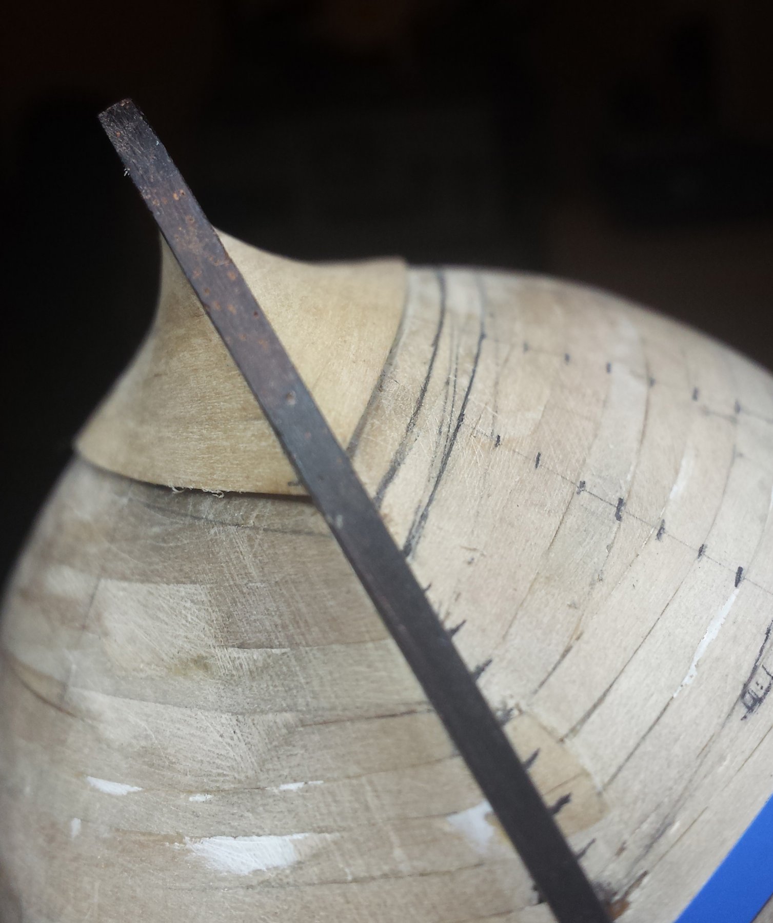
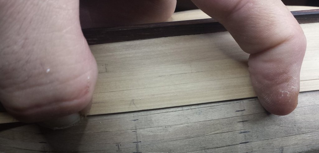
BTW, again for new people, this is the circumstance that I've run into most often that causes gaps in planking. The below drawing is very exaggerated for demonstration purposes, the reality is usually more subtle and sometimes extremely so. The biggest problem is noticing them, especially the very subtle ones. The most obvious way to see them is by testing with the plank you intend to glue on, keep bending it to follow all the segments, you'll see most of them here. The very subtle ones are on lines that are almost straight - basically the less curve there is overall, the harder it is to see the flat. These I found I could detect with my spring steel sander thing, I move it down a plank edge with a little bit of pressure at a steady and fairly slow pace. Periodically the sander will feel like it slips. That's your flat. You keep fixing and testing with the sander, eventually you'll do that test and you'll feel consistent resistance the whole way. Bravo! You have perfect continuous curves at that point that shouldn't have any gaps. I think there's nothing special about the spring steel there and any little sanding block with a gentle curve (like my steel sander has) will do.

- 714 replies
-
- 4
-
-
- lady nelson
- victory models
- (and 1 more)
-
Miniature Hand Tools
vossiewulf replied to Julie Mo's topic in Modeling tools and Workshop Equipment
Artco Tools has a better selection, I should have known that as they seem oriented toward supplying the remaining real-life die makers. Most of the professional rotary tools, particularly the air-powered ones, seem primarily designed for polishing molds. This is my other favorite one, again safe edges all around, very simple narrow rectangle shape with all upper surfaces beveled back to reduce interference, it's the perfect tight-corners file. (Terrible low-res pics that were badly upscaled at some point on Artco) Now with "In Action" screenshot!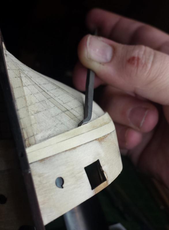
-
Fokker Dr.I by Torbogdan - FINISHED - Model Airways
vossiewulf replied to Torbogdan's topic in Non-ship/categorised builds
Congrats Tor, glad you are very happy with it, that's the only thing that's important in the end. -
Miniature Hand Tools
vossiewulf replied to Julie Mo's topic in Modeling tools and Workshop Equipment
I think we agreed that riffler file sets are what you need next? Certainly if you don't have a good set, you're going to find tremendous use out of that as a purchase. The annoying thing is the set I bought is no longer available anywhere. There is this Glardon-Vallorbe set at Otto Frei, but I don't think the choices in that set are the best for ship modeling. I think the best choice at this point is to buy individual Grobet files, Contenti is a good supplier that I've bought from for years. In fact you should add them to your supplier list, they are jeweler/watchmaker supplies like Otto Frei but they have some things Otto Frei doesn't. I tend to use Otto Frei because I get next-day delivery on standard shipping as they're just across the bay from me. Some things about rifflers - you want diesinkers' or diemakers' riffler files. Almost all suppliers call them diesinkers as a group now but sometimes you run into ones that know that there is a division there and will list them as two separate groups. DO NOT get silver smiths' riffler files, they are much too big. Unless you want an 800 pound gorilla riffler to teach a 1/24 build what's what. You want both cut 2 and cut 0. Those would be medium and coarse respectively when used on wood. If you can only get one... I'd probably get 2 as you can use it in precision cases, it's just not as good at removing large amounts of material. Number 901 is the one I use most, it has safe edges all around and you can do fairly big areas laying it flat or very tiny areas with the pointy end. Number 951 is generally useful but it also seems specifically designed to help make clean planking rabbets quickly. Click here to see it in action doing that (toward the end of the linked post). My other favorite is missing... I'll have to look around to find another supplier who has ALL Grobet rifflers, you can see there are many numbers missing from Contenti's list. There are others they have that are useful, but each of you should decide from here which ones will help the way you work. I do strongly recommend you focus on the ones with safe edges, if you have cutting surfaces all around it makes them more flexible but also capable of causing as many problems as they're solving. -
Miniature Hand Tools
vossiewulf replied to Julie Mo's topic in Modeling tools and Workshop Equipment
Yep, obsidian and flint were the first scrapers, and glass was very popular as scraper material throughout the 18th and 19th century as I recall, and still works fine today as mischief says, you just have to be careful handling it and the edge is not going to be regular. Every edge tool you own can also act as a scraper, and I regularly use them as such in small areas. As long as you don't do it too much, using them this way doesn't significantly increase sharpening requirements, at least in my experience. -
Miniature Hand Tools
vossiewulf replied to Julie Mo's topic in Modeling tools and Workshop Equipment
*Poster is not responsible for any resultant marital strife and/or budget destruction You guys are just joining me. Because I do all this digging I've been living with years-long wish lists forever Even now that I'm in a position to spend quite a bit more than I used to, it's STILL years long. But at least if you know all the cool things out there, you can make better judgments about priority and get the ones that will benefit your processes most first. -
Miniature Hand Tools
vossiewulf replied to Julie Mo's topic in Modeling tools and Workshop Equipment
Yeah, if you want good chisels or planes with blades that stay sharp near forever, most of Lee Valley/Veritas tools now have the PM-V11 powdered metal alloy as an option. You pay more but the reduction in sharpening time makes it very worth it. -
Miniature Hand Tools
vossiewulf replied to Julie Mo's topic in Modeling tools and Workshop Equipment
See the list of suppliers you want to look at that I posted over in my tools thread. I didn't include Lie-Nielsen as they are out of most folks' price range. -
Miniature Hand Tools
vossiewulf replied to Julie Mo's topic in Modeling tools and Workshop Equipment
Geez just realized that last post was pretty much of a repeat like three messages upward. Sorry for the repetition. -
Miniature Hand Tools
vossiewulf replied to Julie Mo's topic in Modeling tools and Workshop Equipment
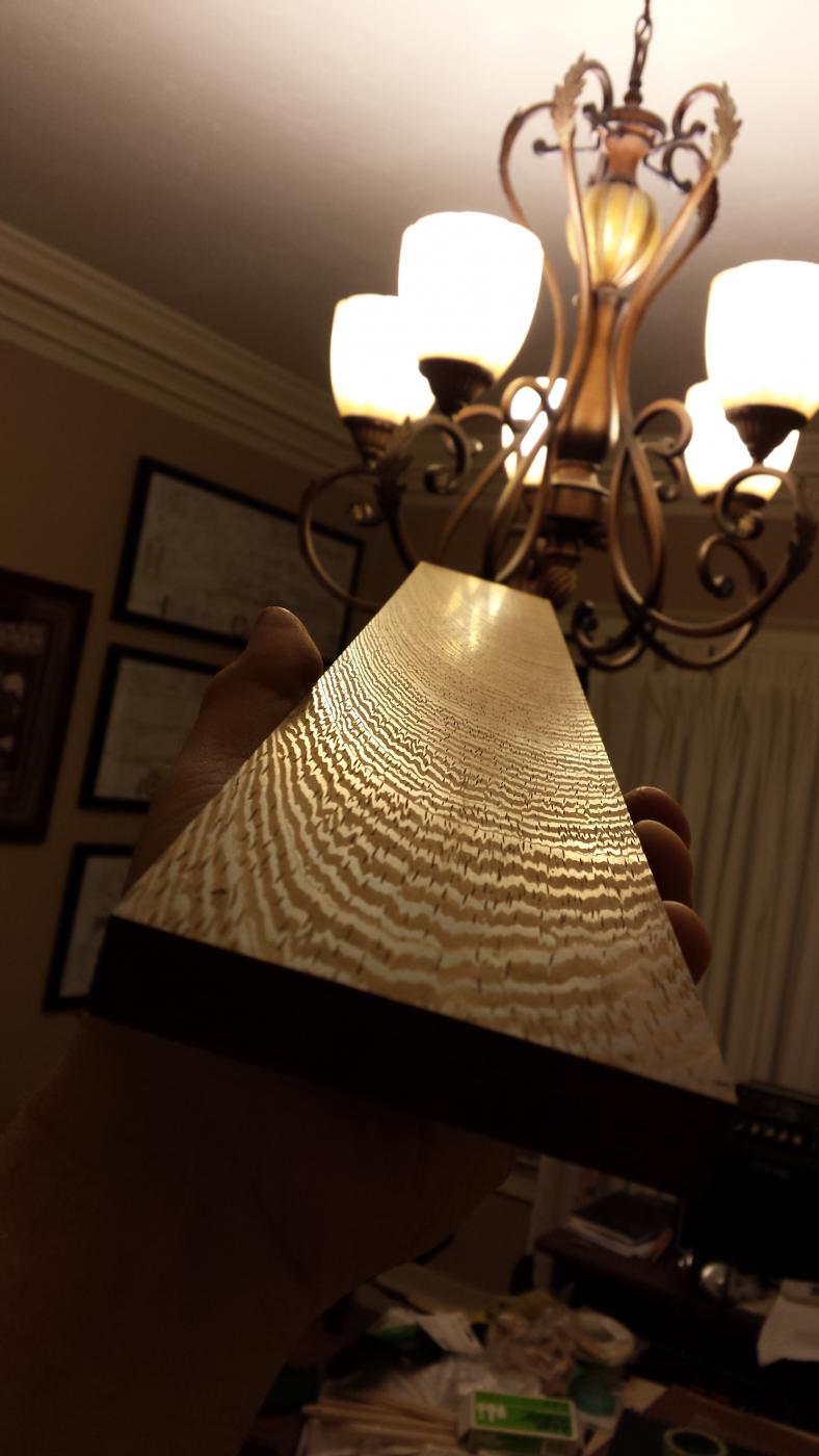
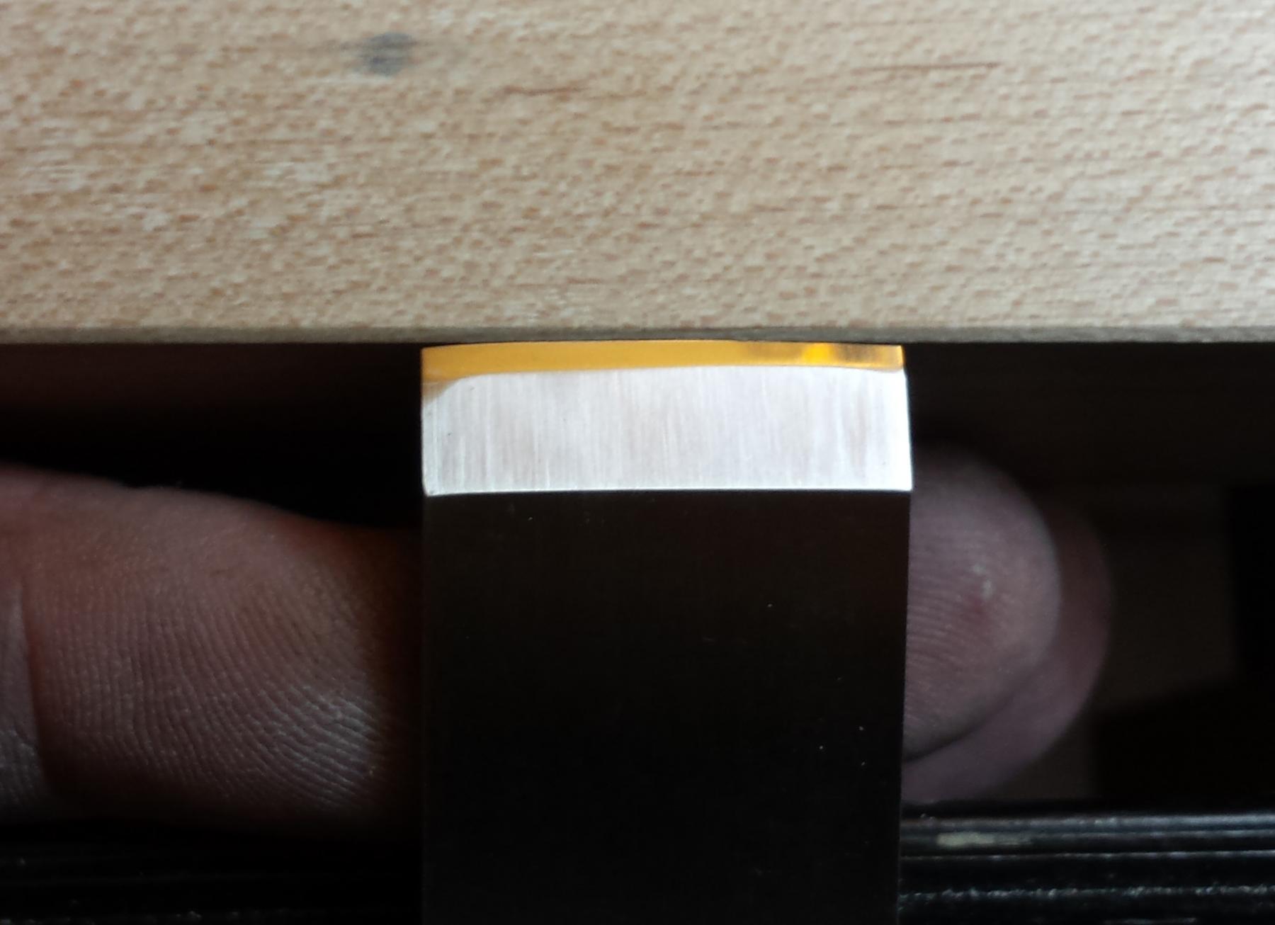
The Kell is an excellent chisel sharpening jig. I don't however think it's a good plane iron sharpening jig. Plane irons should be sharpened not with a straight edge and hard corners, but with a .005" to maybe .01" radius. A square-edged plane is not very good for the task of actually planing down stock, every cut leaves a deep hard edge or two deep hard edges. However, if the iron is sharpened with a gentle radius, the cut feathers out to nothing on both sides and you can easily produce a completely flat planed surface by overlapping strokes right to left or vice versa. The Veritas Mk.II is designed to make it easy to sharpen in that radius, and every plane I own is sharpened that way. Here's an example, I had just bought a Veritas low-angle jack plane, and had just sharpened it for the first time with the proper radius and used it to flatten this wenge board. If you can make a wood surface flatter and shinier than this, please let me know how And here is my little Lie-Nielsen plane that I use most on ships, showing a good but slightly lopsided radius on the edge, I straightened it out the next time I sharpened. And speaking of which, if you want to buy good tools now, you need to spend time at both Lee Valley and Lie-Nielsen.
-
Miniature Hand Tools
vossiewulf replied to Julie Mo's topic in Modeling tools and Workshop Equipment
See Ron Hock's book on sharpening that I linked in my tools topic, it really is the best and most straightforward I've read. I strongly recommend Shapton Glass Stones. I have an entire drawer filled with sharpening stones of every variety; Japanese water stones work as well as Shapton Glass stones but are much more messy. Diamond is 1) expensive for the rate at which they wear out and 2) always leaves a really aggressive scratch pattern. Ceramics almost always rapidly glaze over. Shapton glass stones stay reasonably flat for a long time, only require a few drops of water so very little mess, and remove steel at a faster rate than any stones I've ever used. I have a 220 for reshaping bevels, then 1000/4000/8000 for sharpening plus a strop for final finishing. I also strongly recommend the Mk.II Veritas Sharpening Guide if you have chisels and plane irons you want to sharpen. That jig makes plane iron sharpening very easy, including being able to gently radius the edge (never sharpen a plane iron square). -
Miniature Hand Tools
vossiewulf replied to Julie Mo's topic in Modeling tools and Workshop Equipment
That's more or less my state also Michael, and all of my hand saws and about a third of my hand tools are Japanese, most of which came from JW. I very much like the design philosophy of Japanese tools and I very much appreciate Rc64 edges in very good steel, you can get incredibly sharp edges. -
Fokker Dr.I by Torbogdan - FINISHED - Model Airways
vossiewulf replied to Torbogdan's topic in Non-ship/categorised builds
Yeah wow, order it while you can if you have any intention of ever building a Dr.I model. The book has 70 or so pages of nothing but various angles of a very highly detailed and mostly correct Fokker Dr. I 3d model and leaves almost nothing to doubt. -
More tools - Luthier, jeweler, fly-tying
vossiewulf replied to vossiewulf's topic in Modeling tools and Workshop Equipment
For anyone wanting good small ship-modeling planes at a reasonable cost, the Mujingfang planes are a good choice. I have a couple, the iron is plenty thick for this scale and is reasonably good steel. Only drawback for some is they are traditional wood planes that are adjusted by tapping, but that really isn't as hard as you might think once you learn how not to overshoot - that's when they can be irritating. Anyway, almost all are $26 and considering mine work really well after some tweaking and sharpening, that seems to me to be a pretty good deal. One that I have that I find myself using frequently is the bullnose plane, its ability to get into corners is handy. -
Miniature Hand Tools
vossiewulf replied to Julie Mo's topic in Modeling tools and Workshop Equipment
For anyone who's just really into collecting mini tools, Japan Woodworker carries several miniature Japanese tools, tool sets, and planes. -
Thanks folks. I'm sure there's nothing new here, just a synthesis of various other methods and ideas, but it does feel like "my" method now. And important thing there is that means I feel comfortable with what I'm doing. Also, it seems reasonably quick, my slow progress is my job not letting me spend time on it rather than the planking itself going slowly. For anyone who thinks the edges must be glued, the method of letting thin CA run down into the joints works, and it will leave a very fine glue line- I tested. I still have it in my head that it will be more stable in the long run with each plank allowed move a bit, but I'm not sure of that. I'm also going to be sure the treenails are real treenails, probably going all the way through the first planking, to back up the CA with a mechanical hold.
- 714 replies
-
- 3
-
-
- lady nelson
- victory models
- (and 1 more)
-
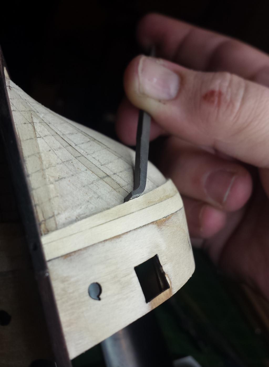
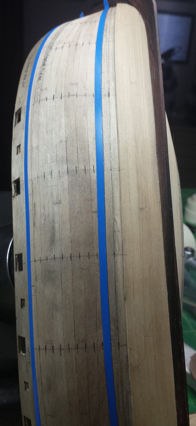
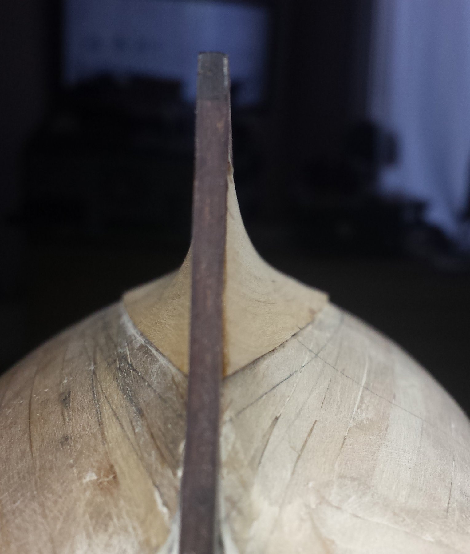
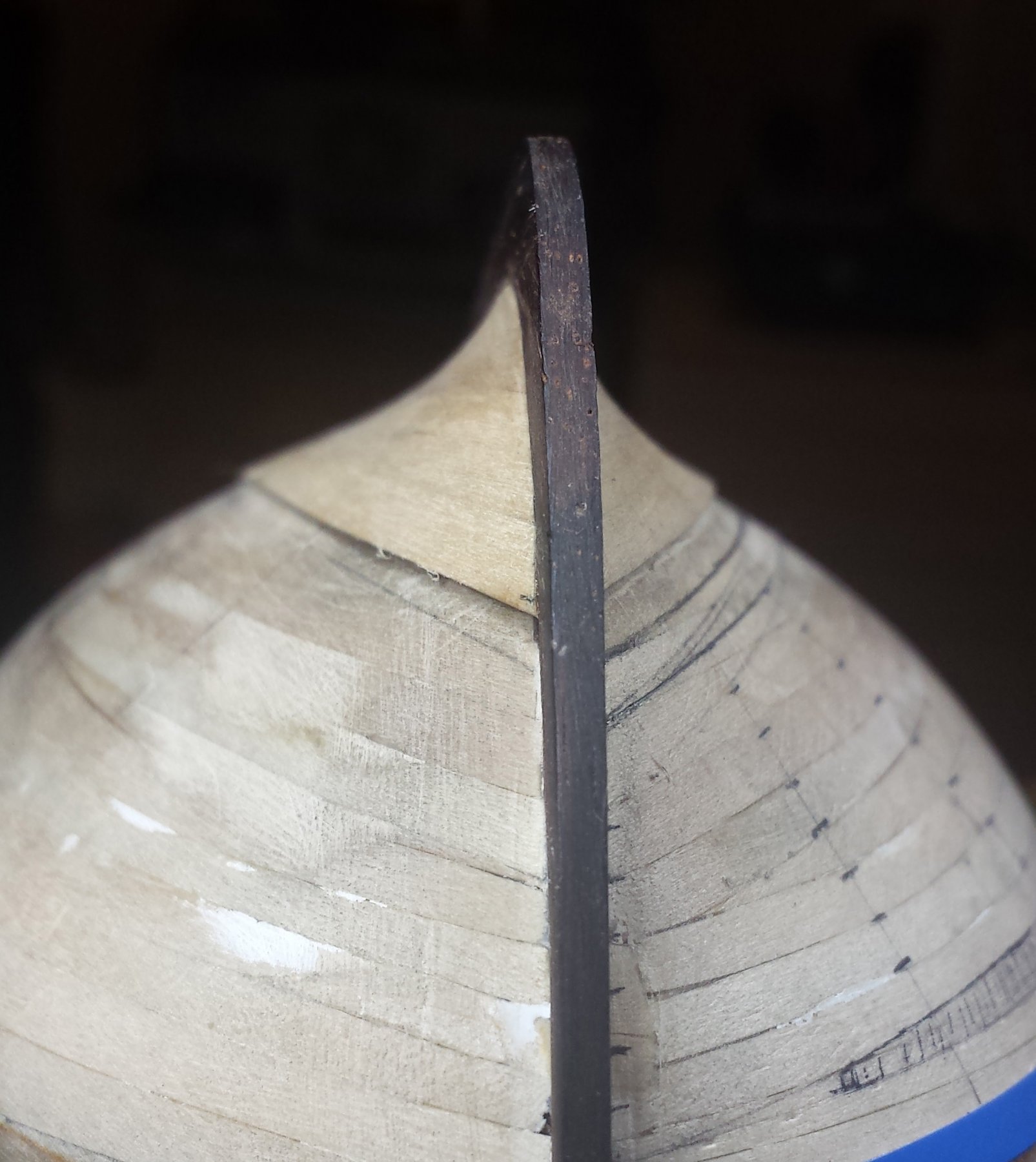
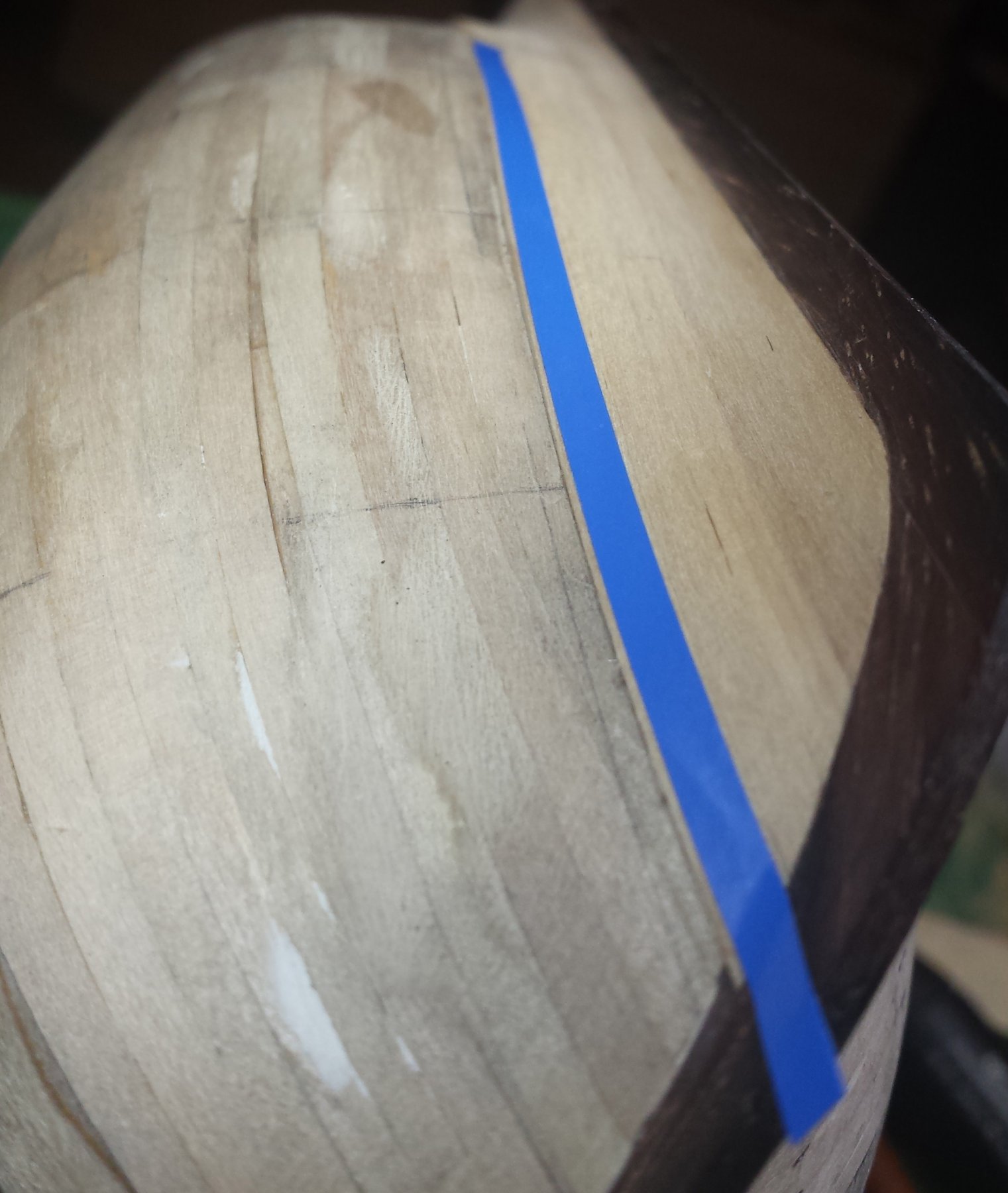
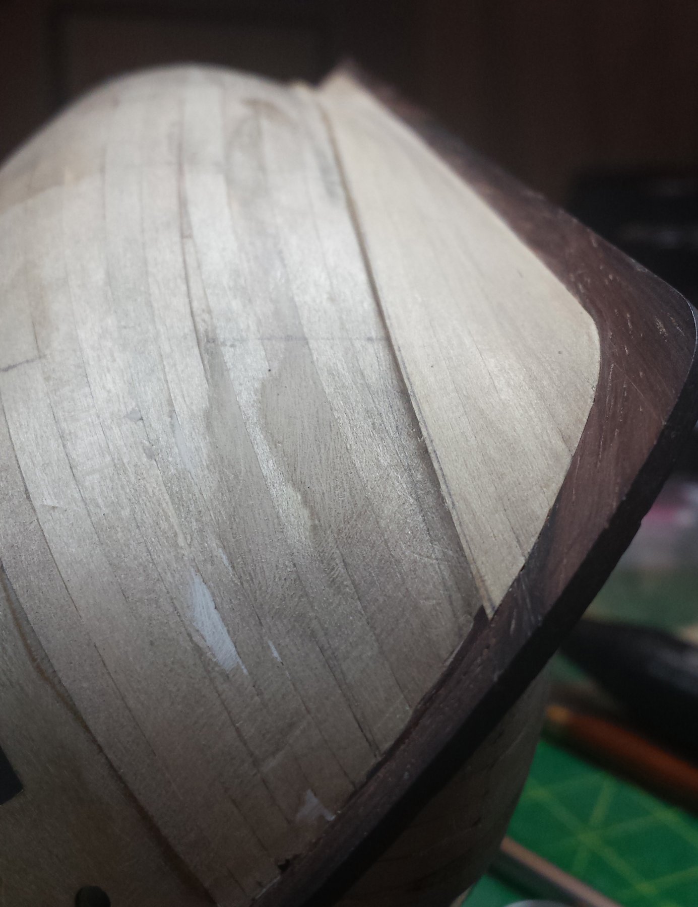
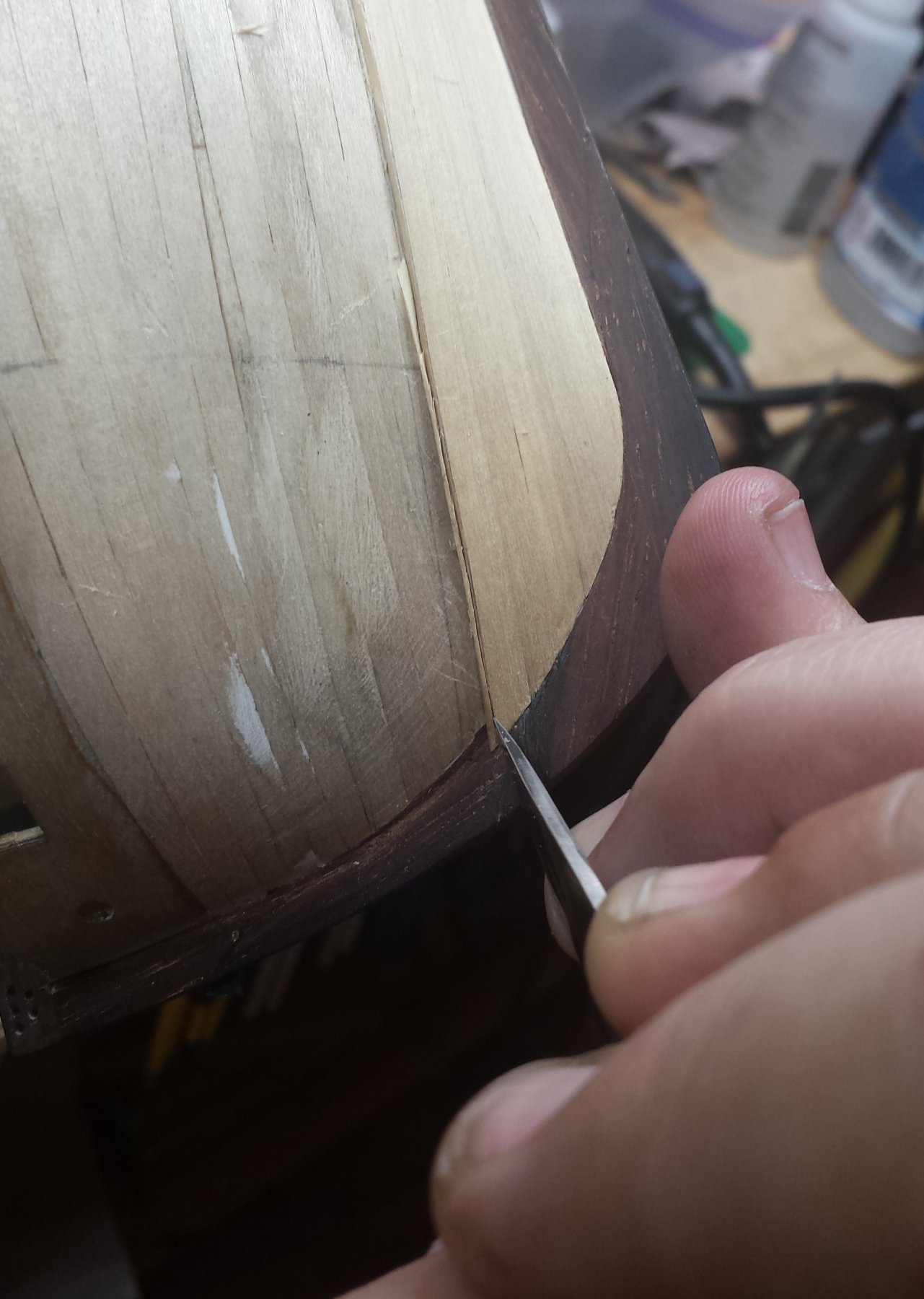
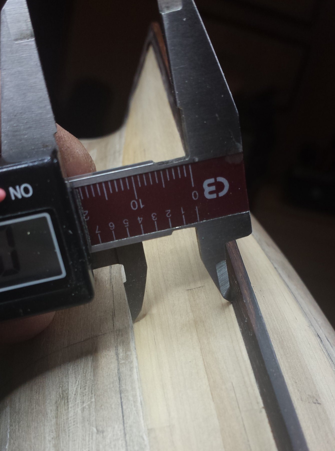
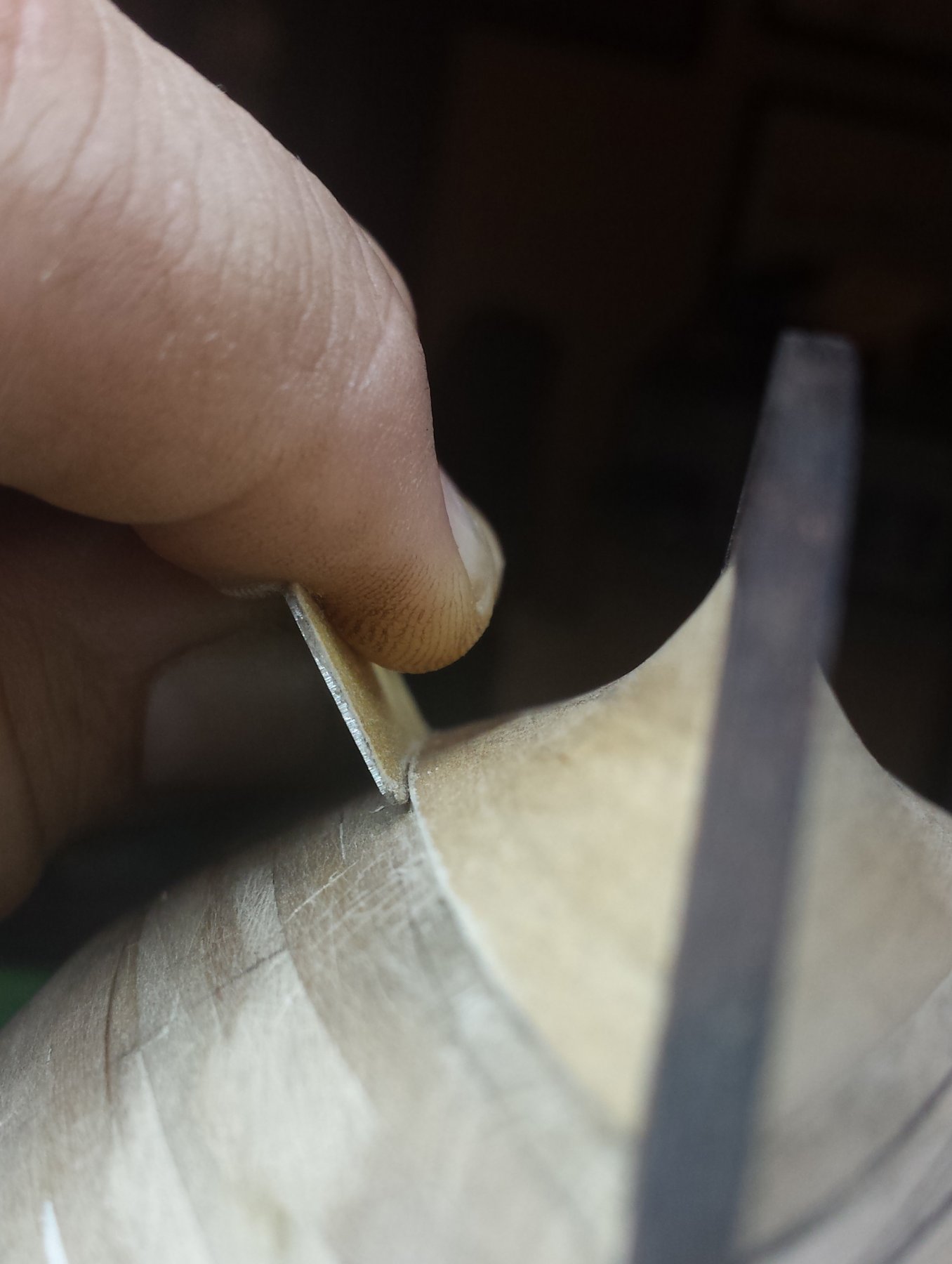
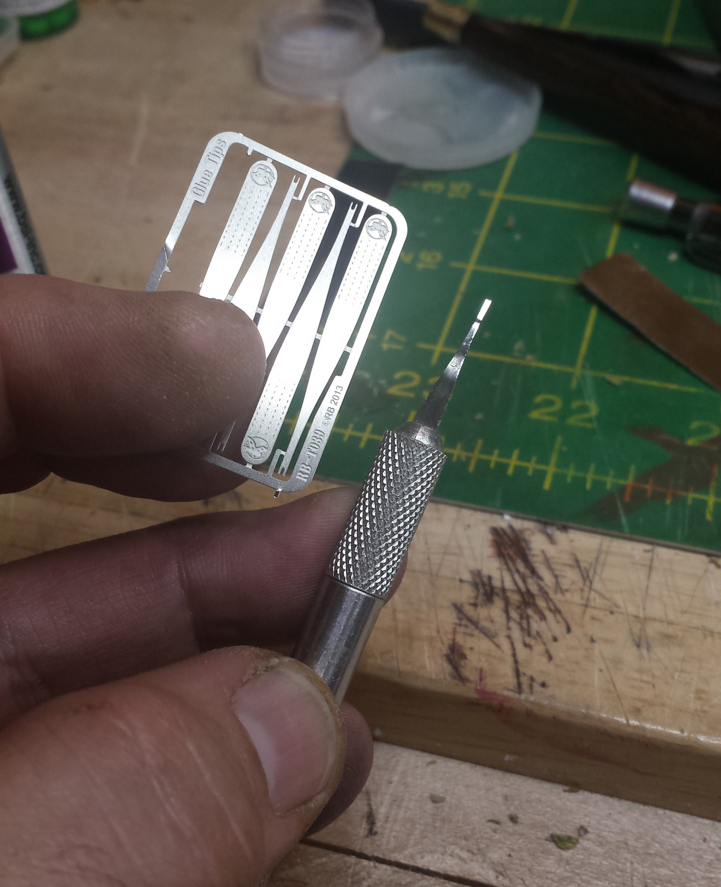
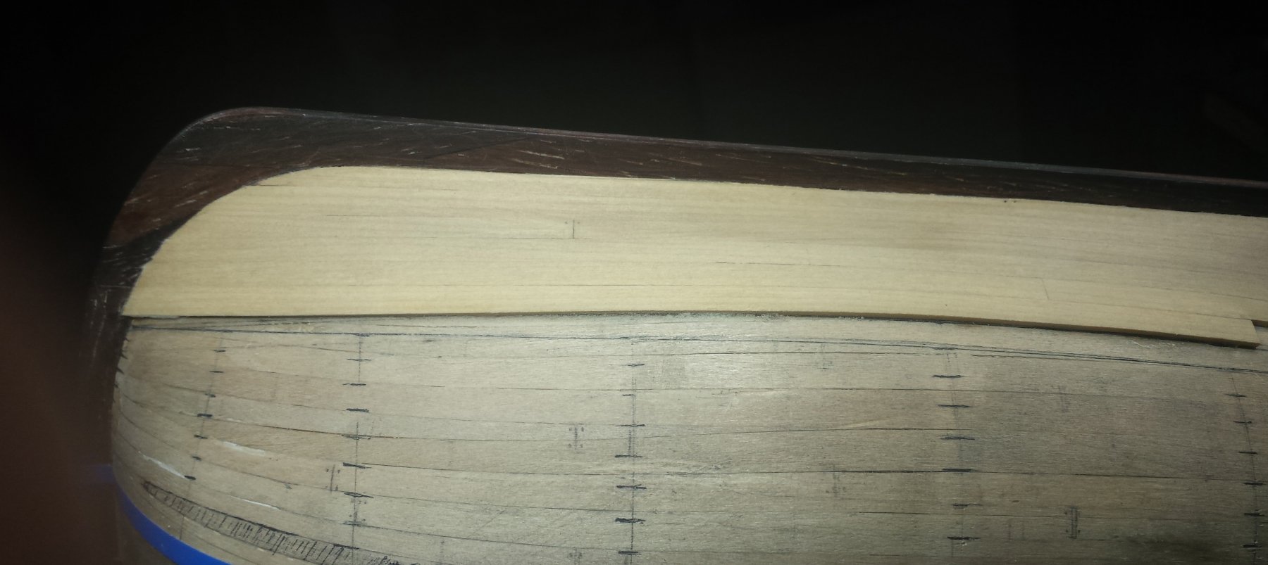
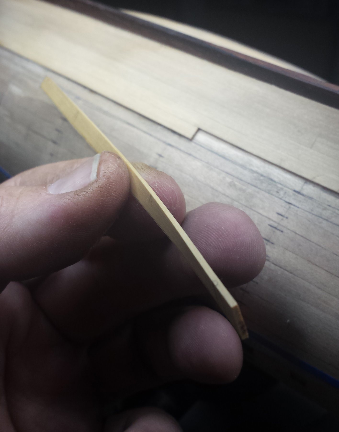
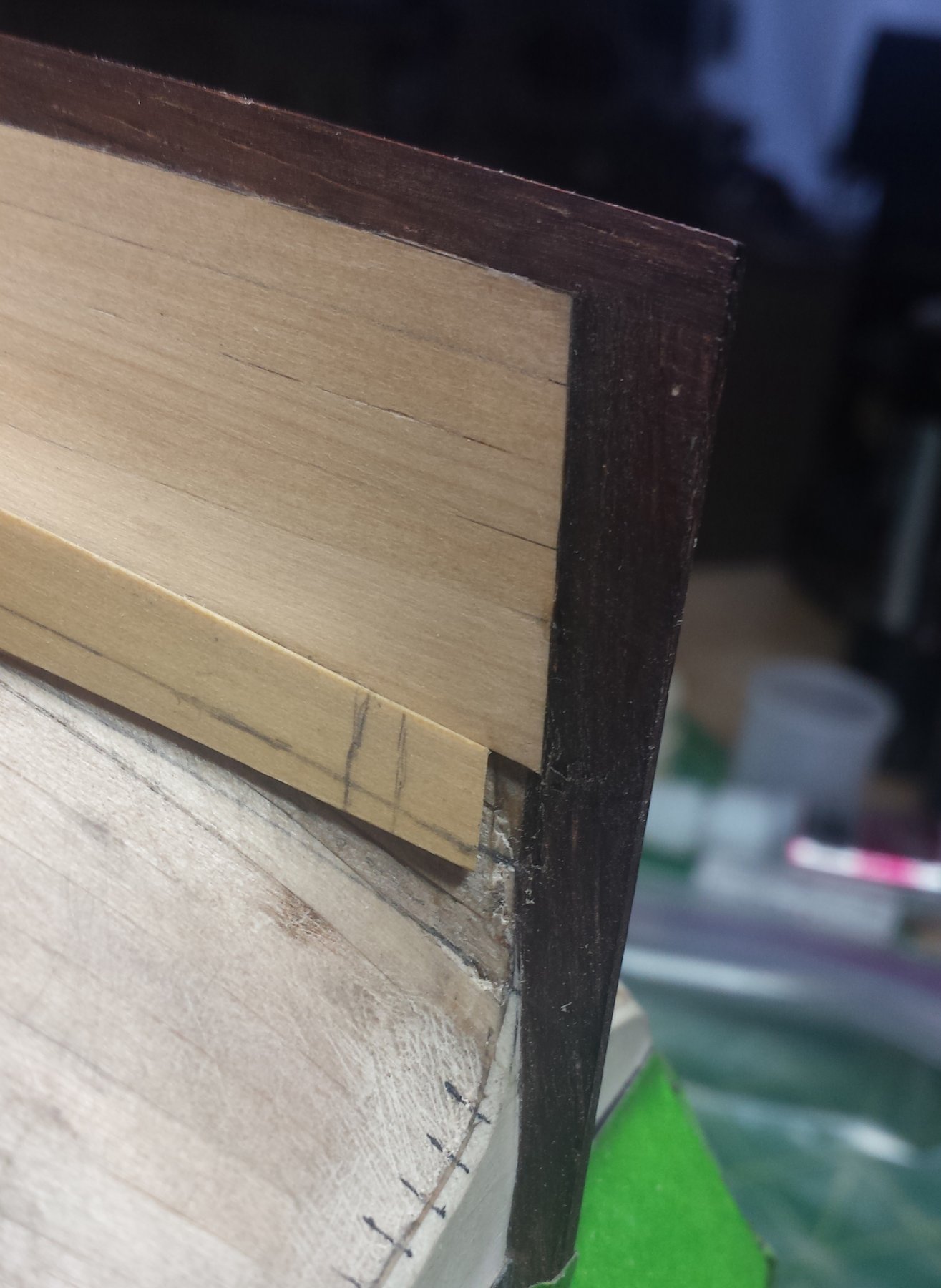
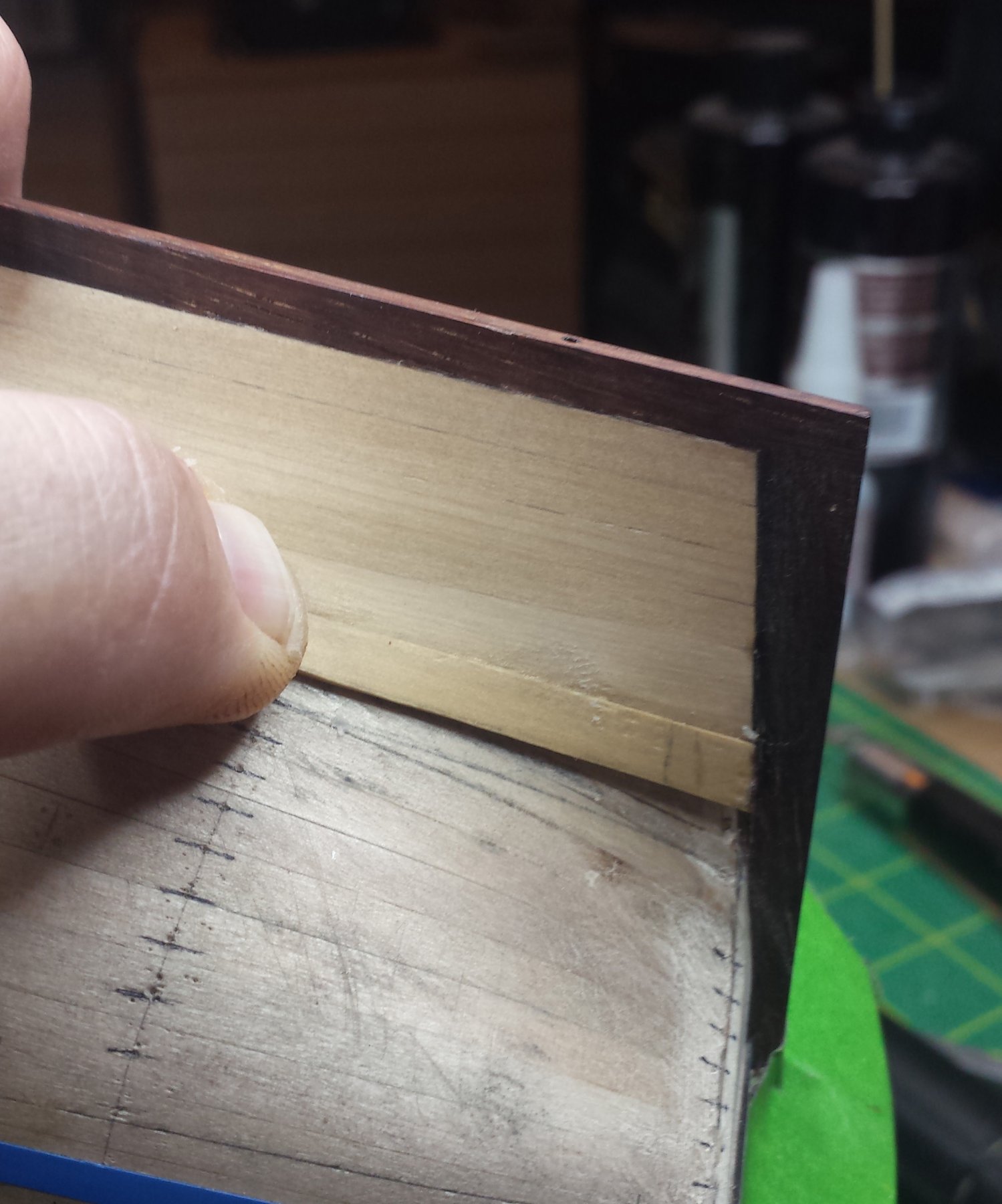
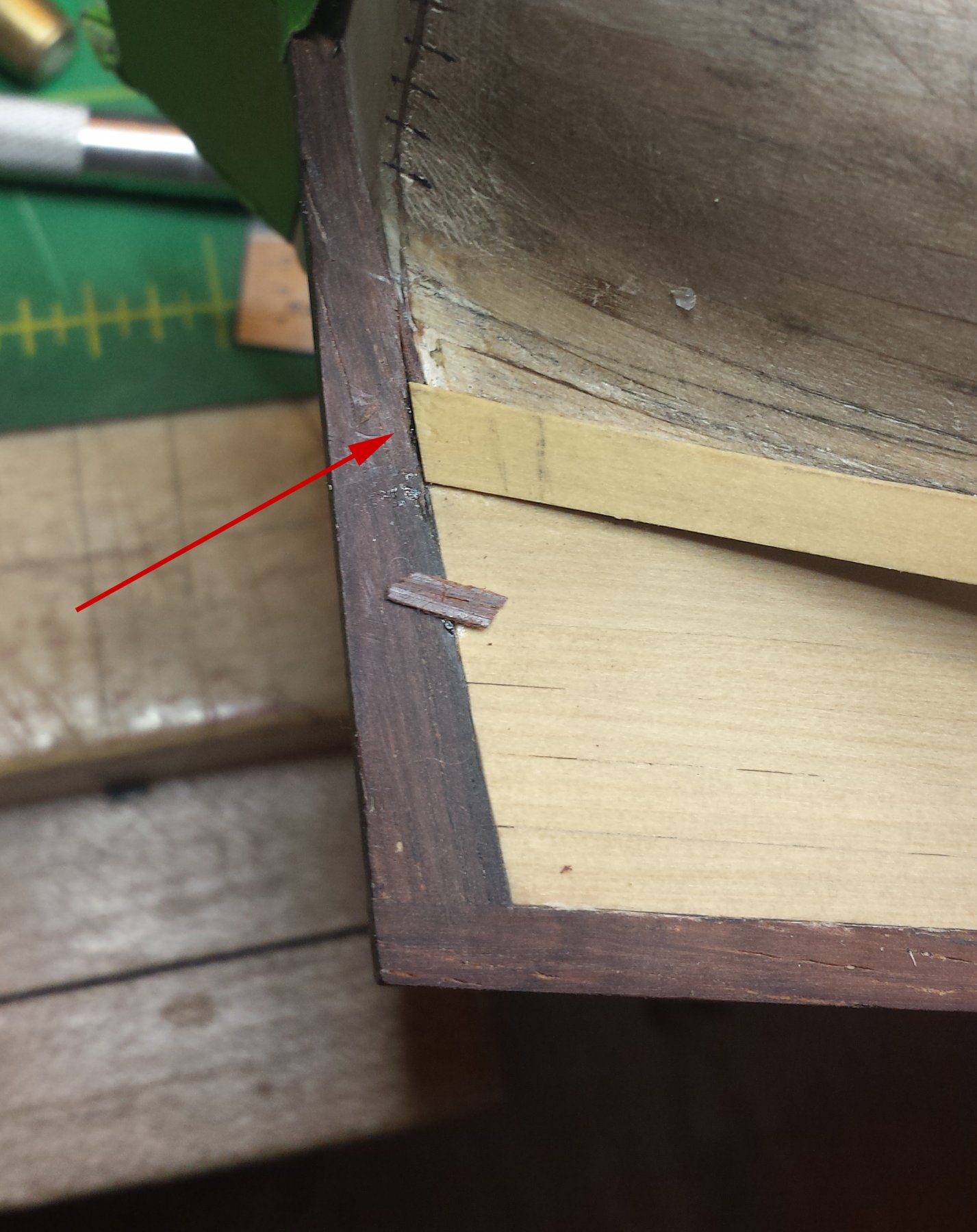
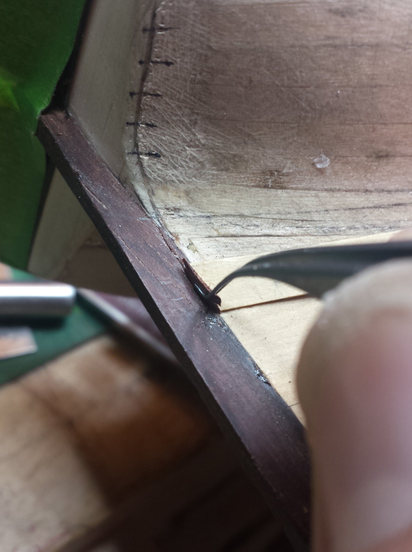
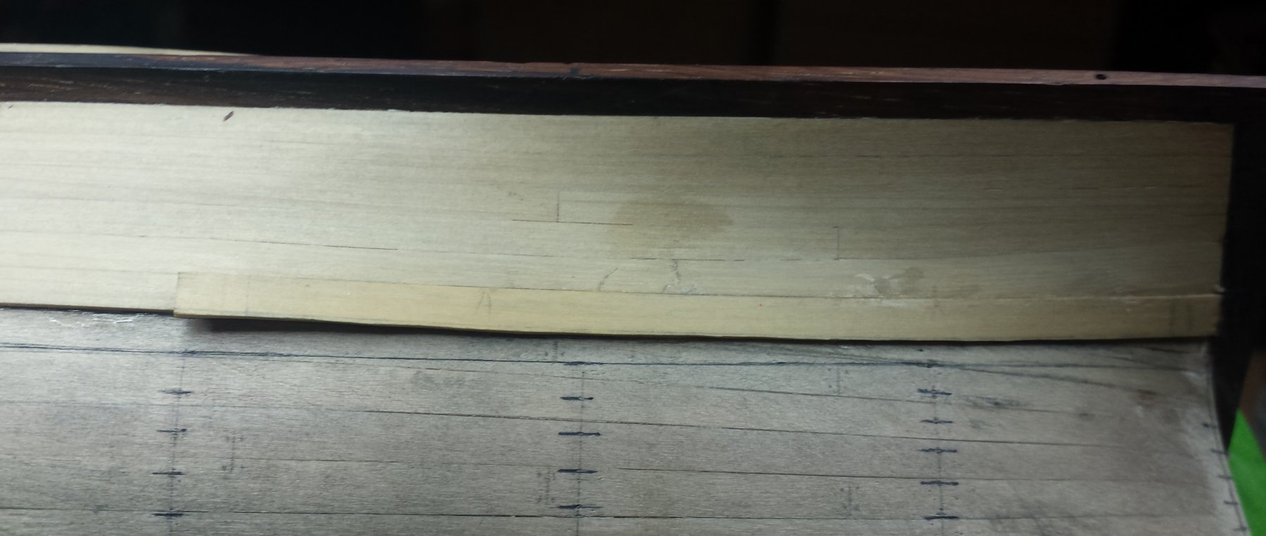
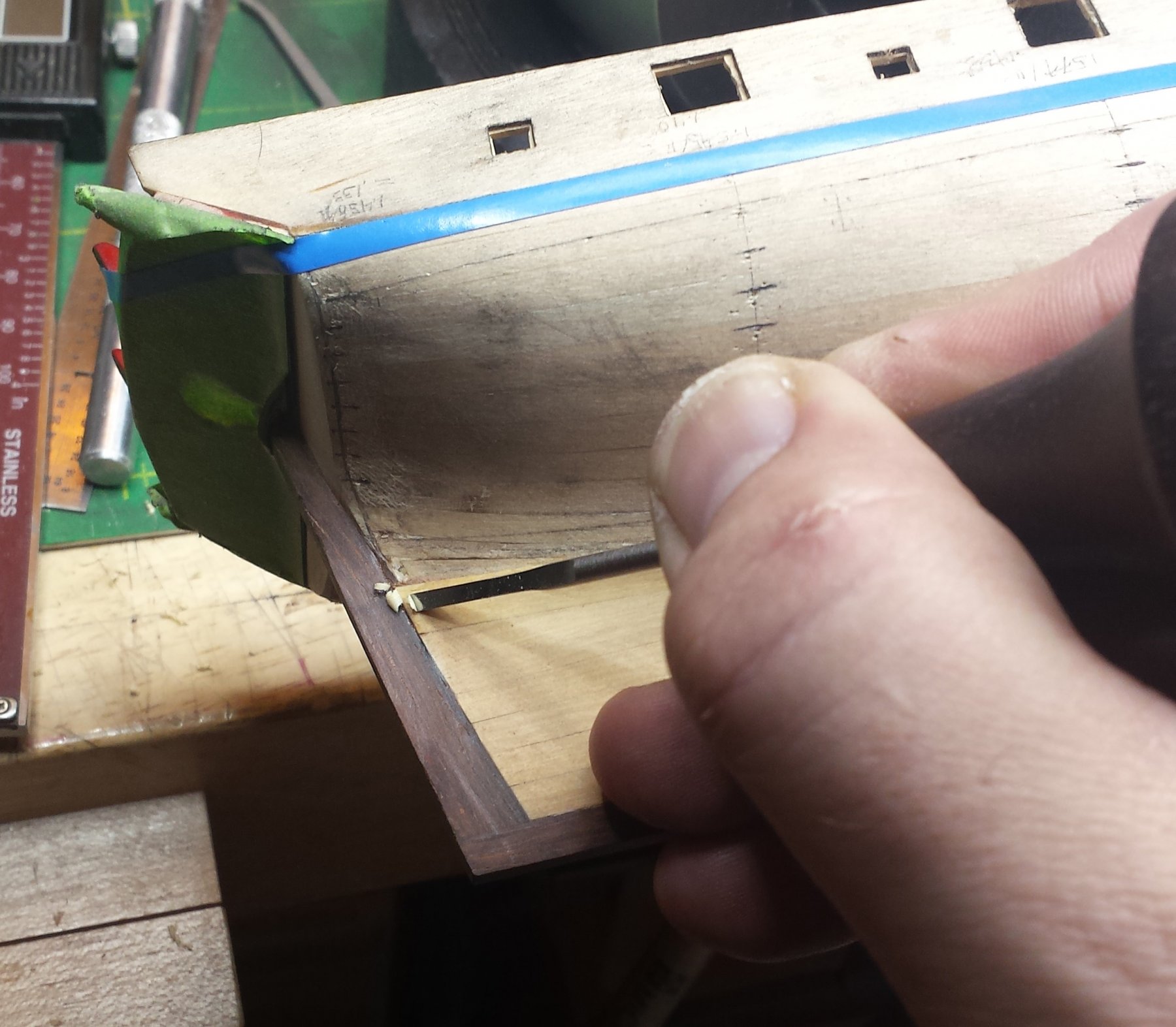
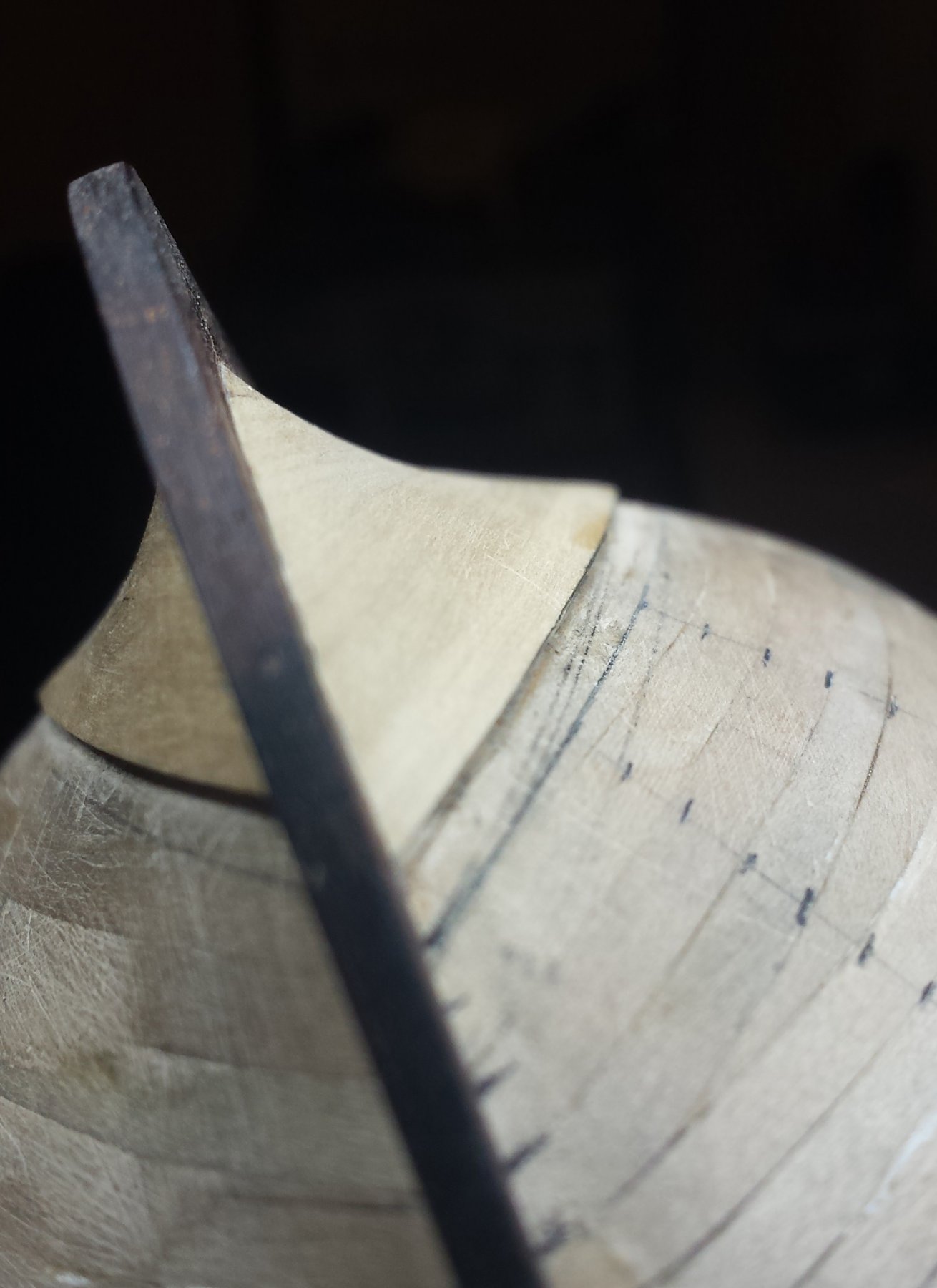
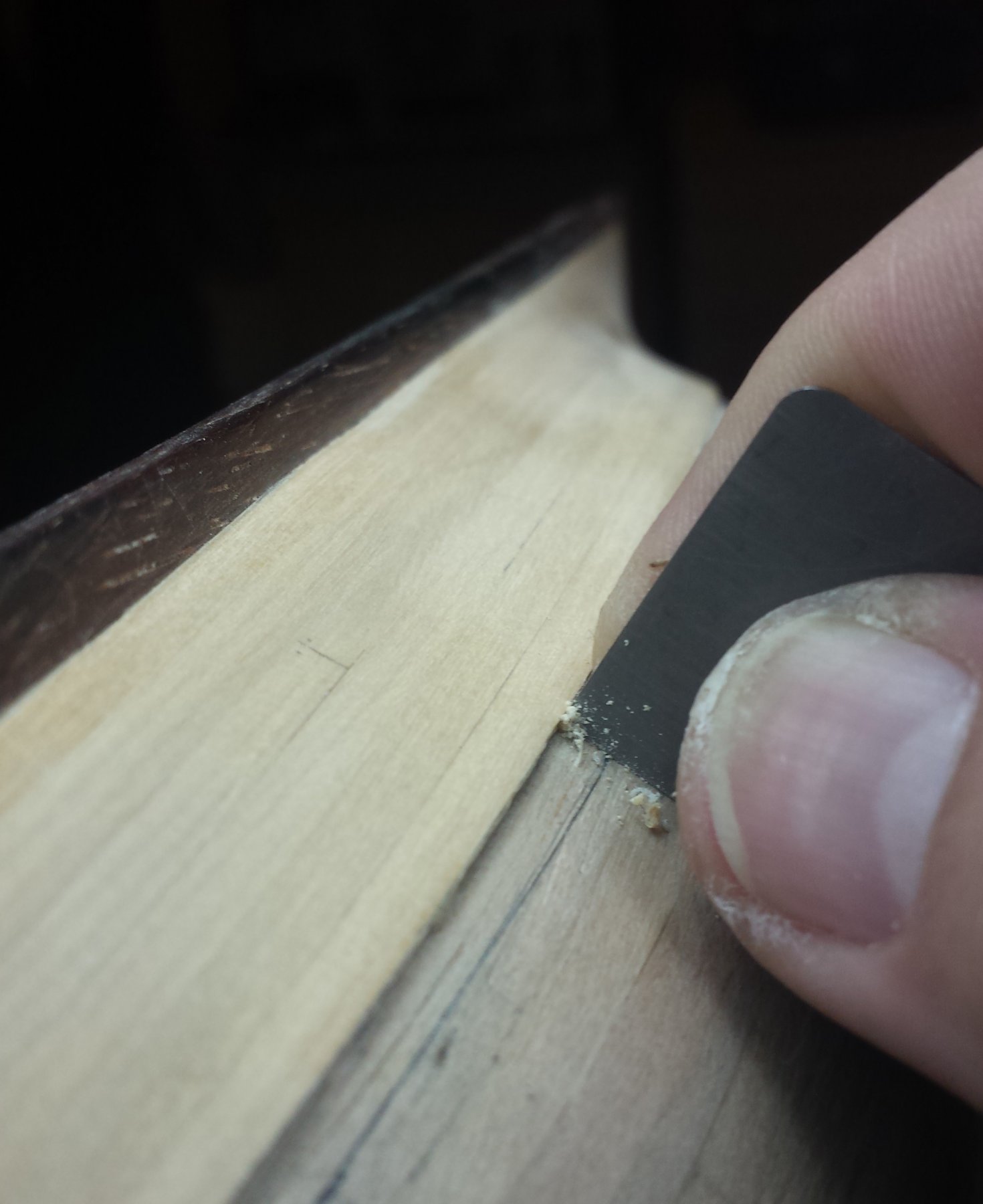
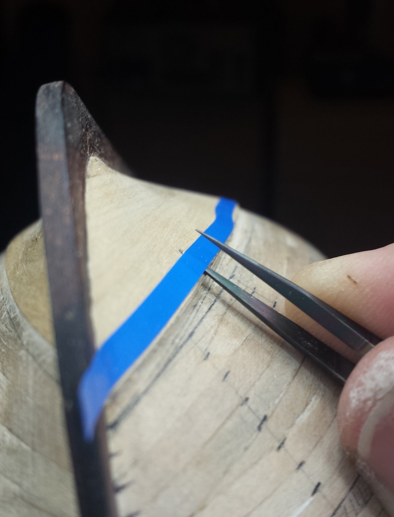
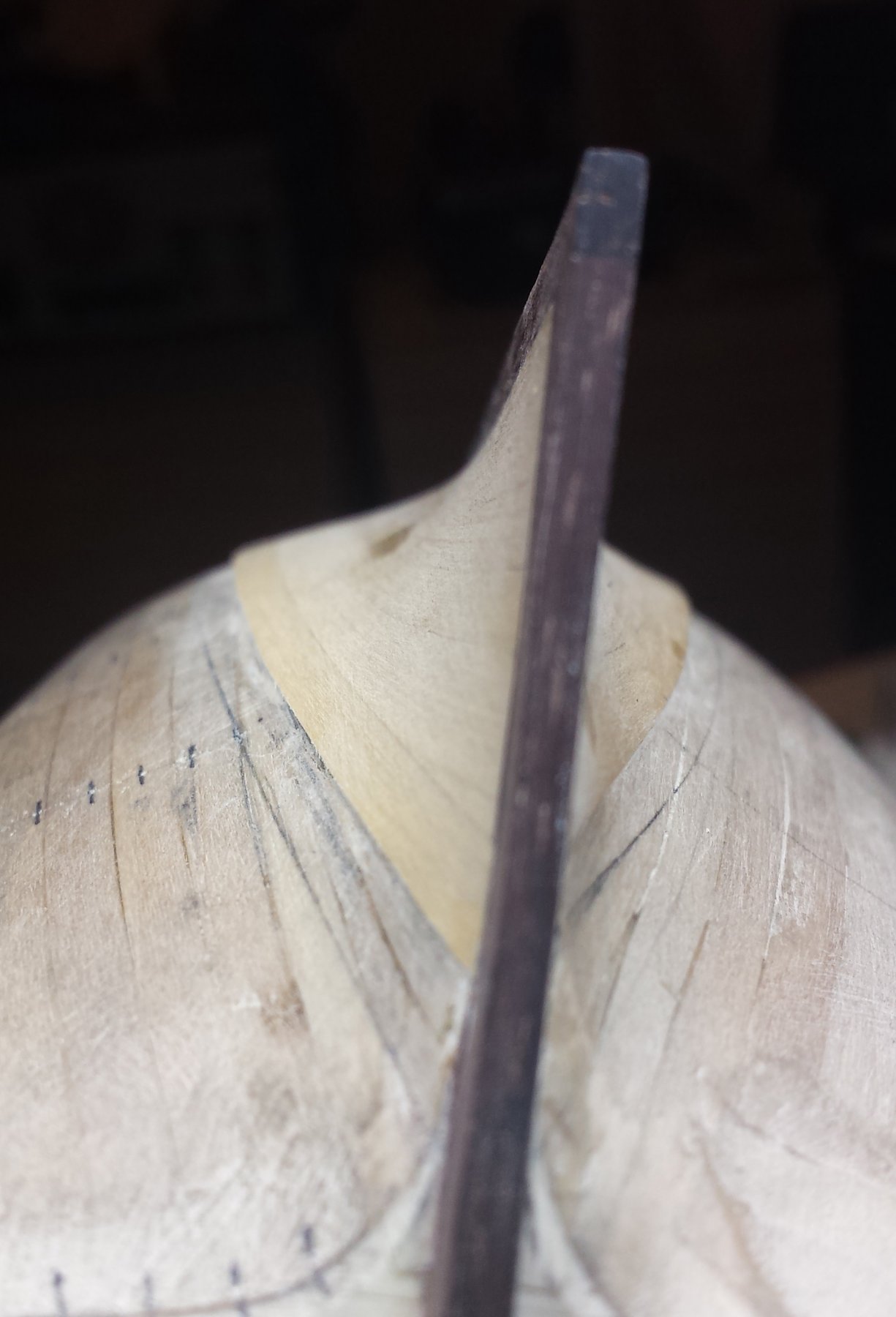
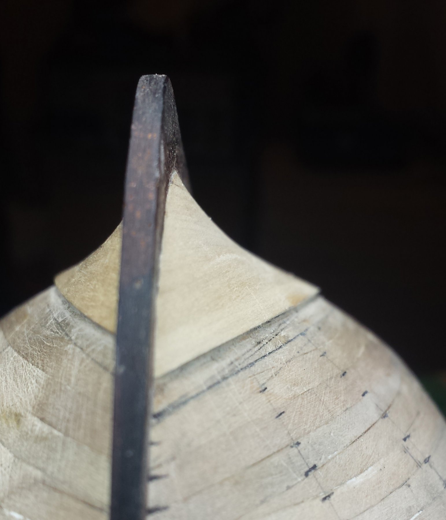
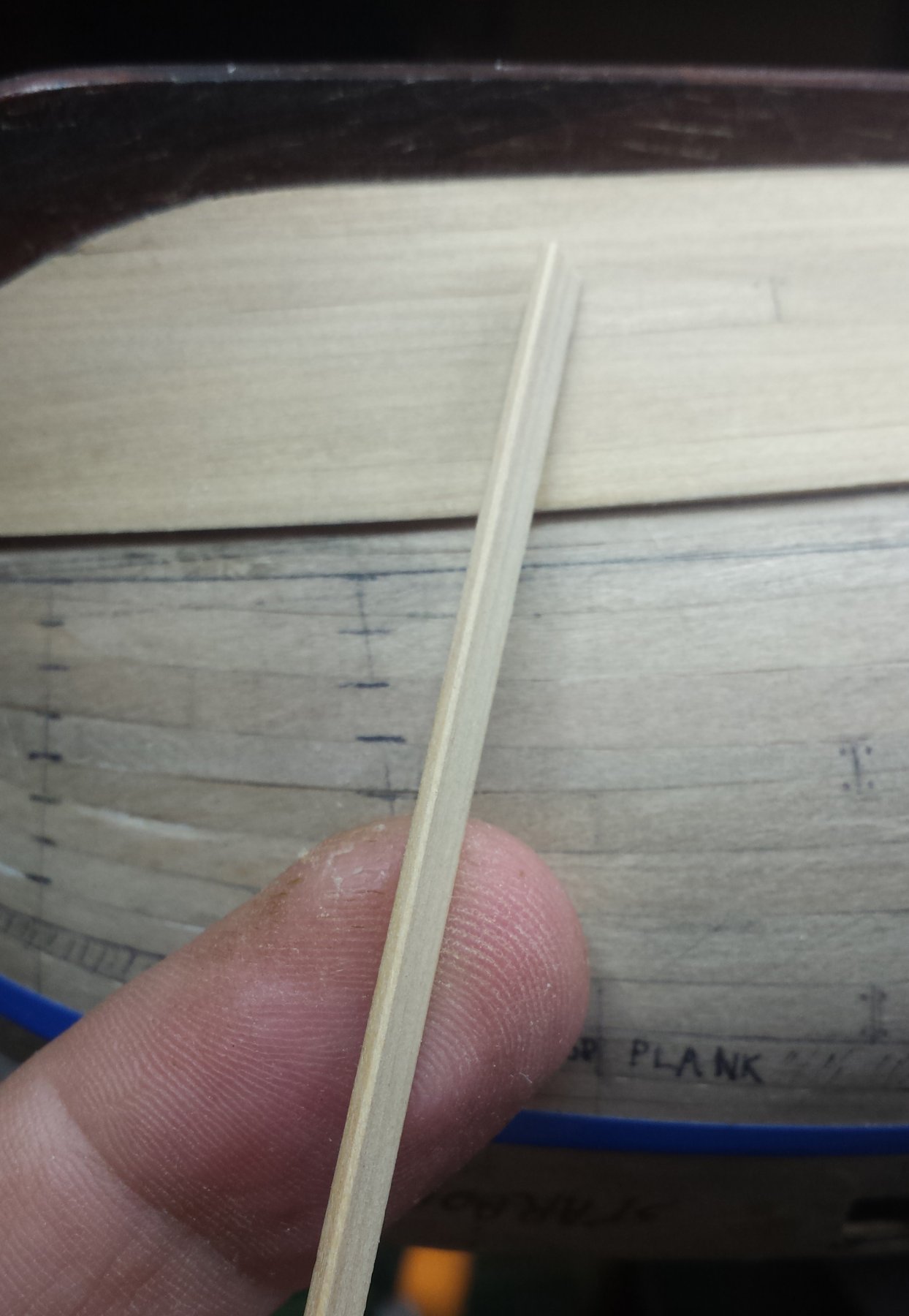
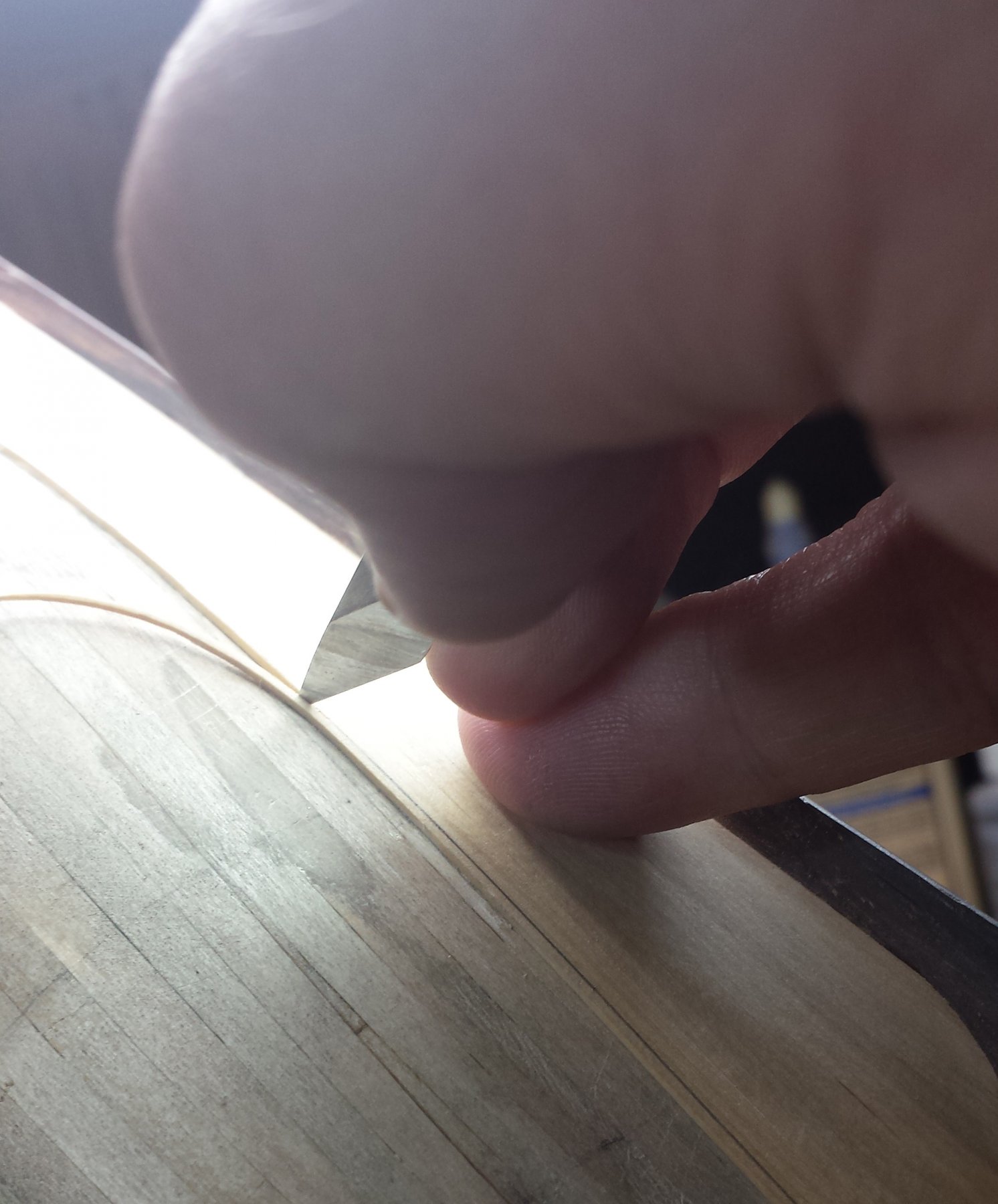
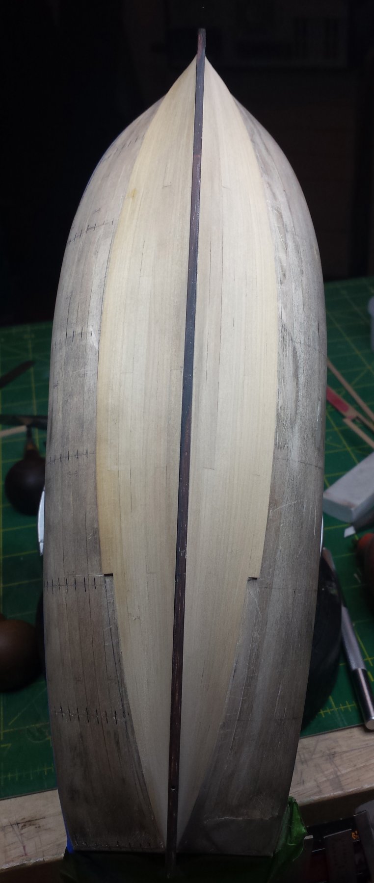
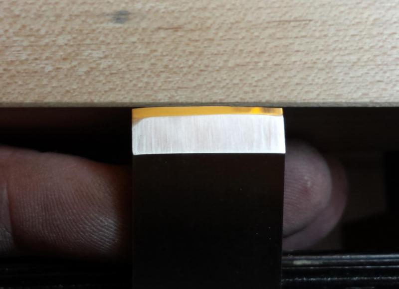
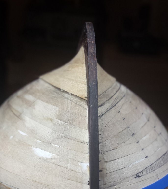
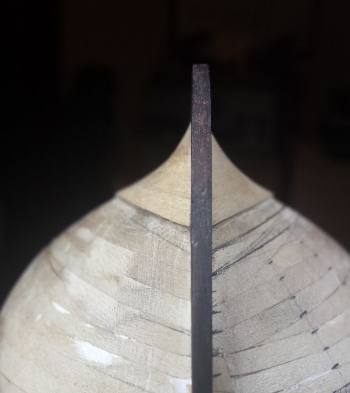
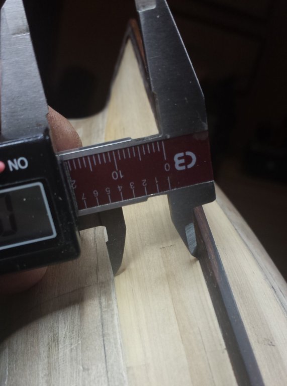
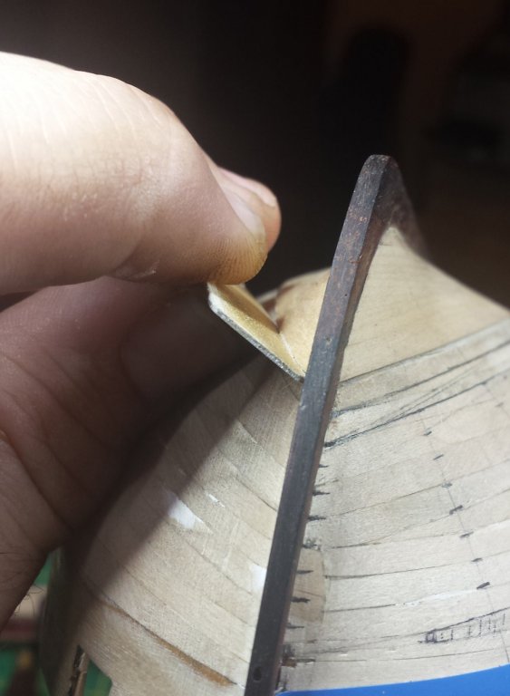
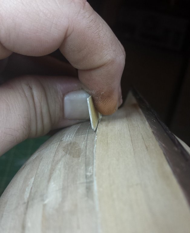
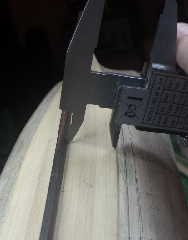
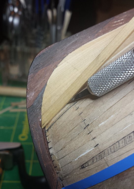
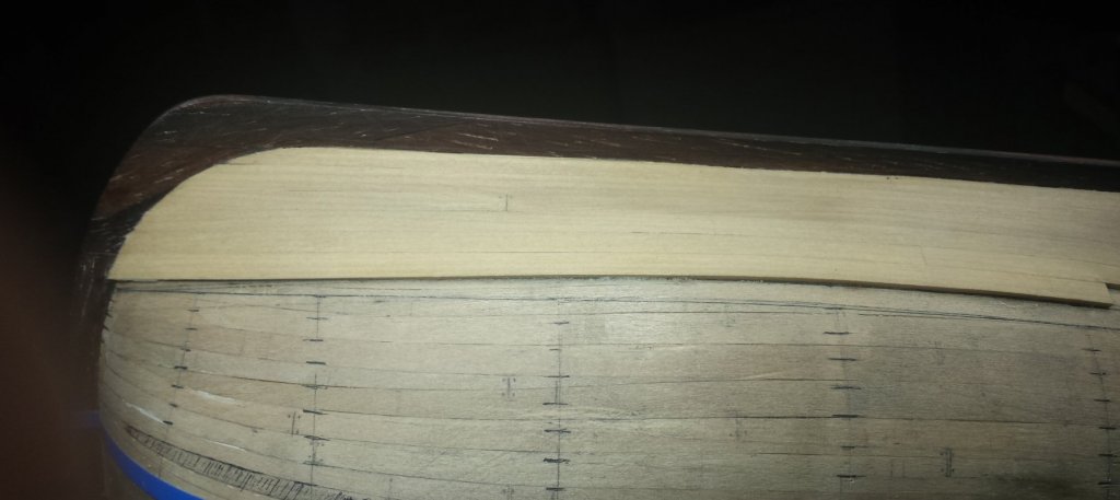
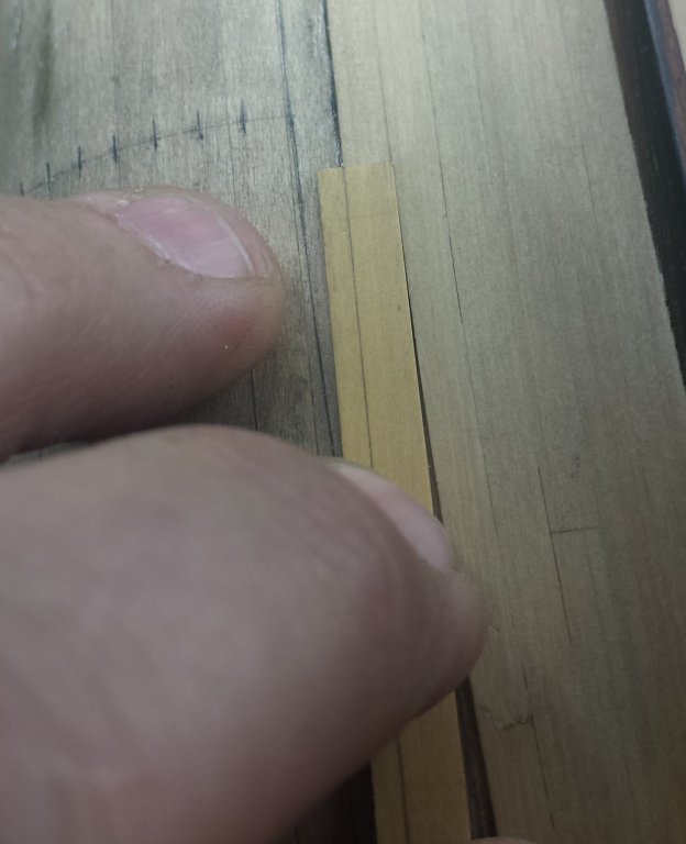
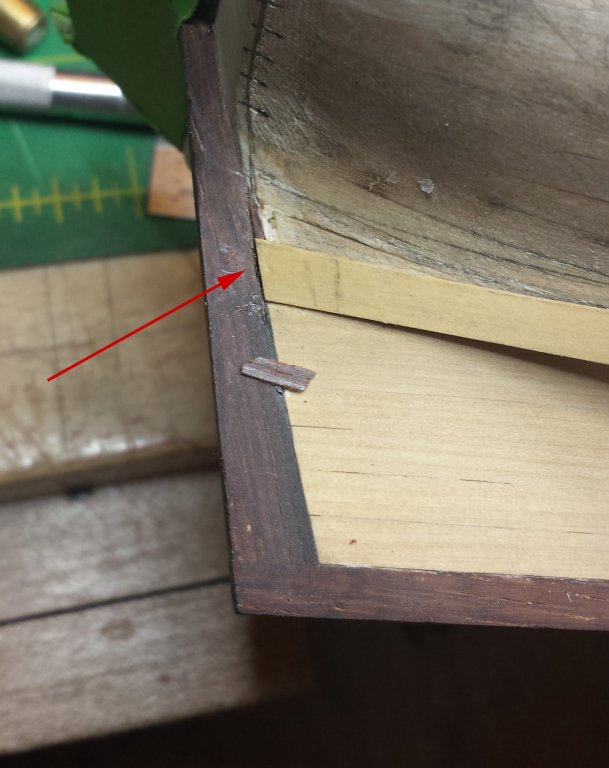
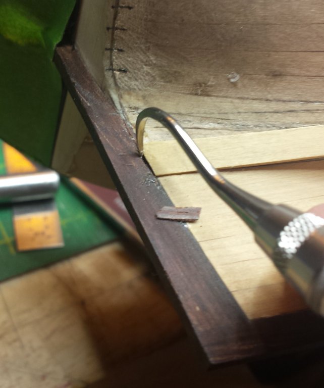
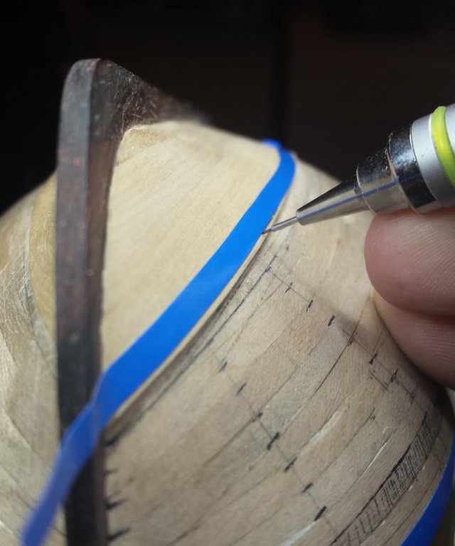
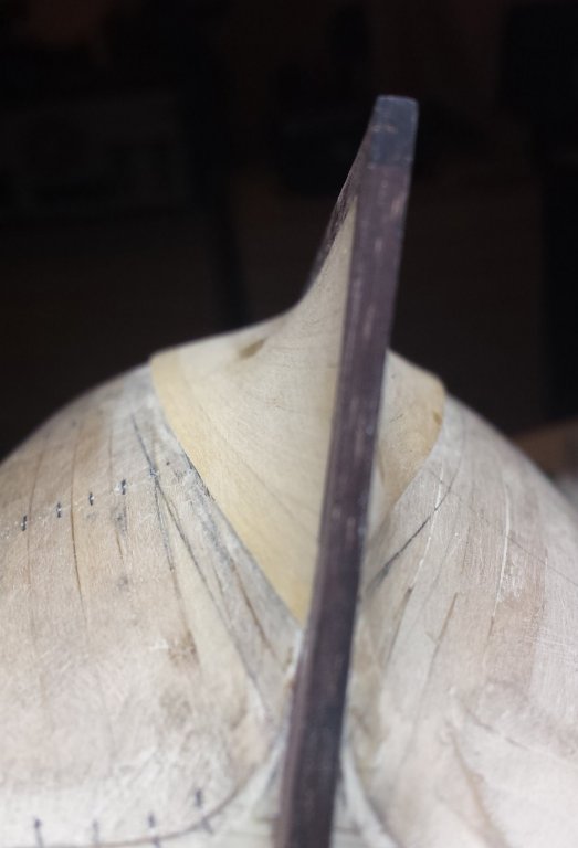
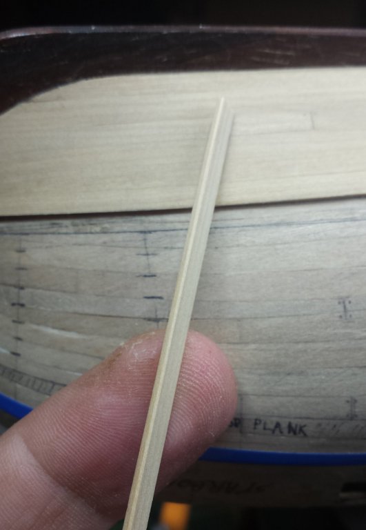
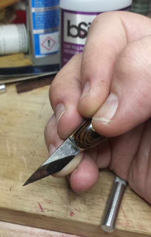
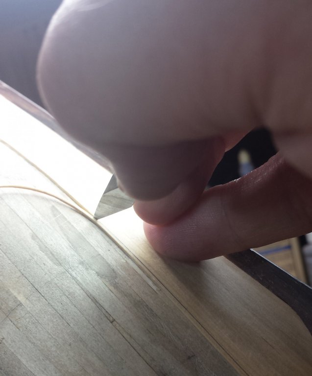
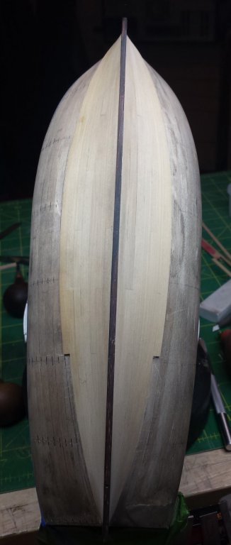
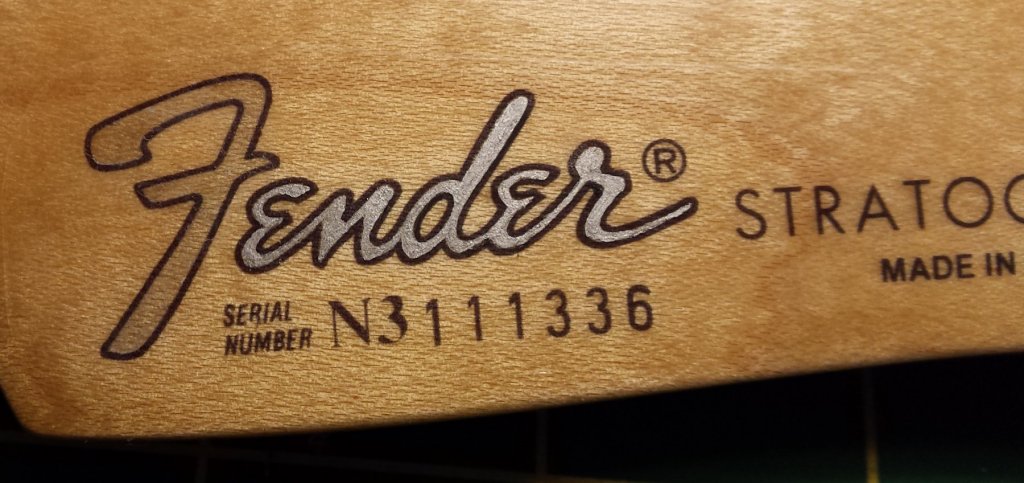
Ok one more long detailed one on planking. After this anybody who's interested in doing it this way certainly should be able to. So after this I'll just have updates showing progress. First my pencil marks on the port side were going so I inkified them. Also I drew in the lines for the next two planks. Doing so gives me a good reference when doing my planking trimming, and also helps make sure we're not drifting in one of the 12,000 ways planking can go bad. With the additive nature it's the sneakiest of any modeling process I've ever seen and until you've done it 20 times you better be checking it from every angle on every plank. The plank lines are really handy when knife-trimming planks because at that point you can't really go far wrong by making the edge of the plank you're trimming exactly halfway between its glued edge and the line of the next plank. I may in the end entirely give up marking planks in favor of that method, since I can get real close by eyeballing that. I am doing all these curving plank lines using flexible plastic lining tape. I burnish that down with the same burnisher I use fixing planks, and then take my .3mm lead pencil and sharpen it on 1200 grit sandpaper What? .3mm is a big fat line! Especially because I never completely like those lines and end up tweaking them by hand into big fat lines. Sigh. Now we'll pick up from the last post, I had just put on the starboard stern plank of the fifth strake. At this point I had to switch to the starboard side to trim and finalize the fifth strake lines, because that establishes the lines I'm going to mirror on the port side. Notice the port side doesn't have all the markings of the starboard side. I finished that, and then did the knife trimming on the stern end of the starboard plank before I remembered to take pics again. So here we are, again I'm getting very close with just my knife. Switching to the bow, I fist mark the end of the plank even with the same plank on the starboard side. I eyeballed down the line to see where the trim should end and marked it- our planks are exactly the right width out of the bag for the middle stations of the ship, so we only need to trim away areas in the bow and stern. Then back to my tape to get the right curve. And pencil mark. And then trim down to that with knife. As nice as it is in terms of increasing speed, I wouldn't recommend cutting as close to the lines as I am unless you're as comfortable as I am with a knife and you know how to make it very sharp. Boxwood in particular is tricky as it splits very easily and you have to feel that happening very quickly to prevent a serious problem. With a good little sanding stick with 120 grit you should be able to remove 1/64" outside the line quickly. This is after knife-trimming. Slight break here to talk about holding knives. Being able to cut really straight lines is much more a matter of technique and less of talent than people think. First, there is the not-rocket science concept that to do something with precision, you need to eliminate ALL unnecessary motion. Here is basically how I hold this knife. All fingers but pinky on the handle. Fingers are not just gripping the knife tightly, they are being pressed against each other tightly. Between the two, that blade is not going to wiggle at all and you can use your arm to pull your hand in a straight line and you're going to cut a very straight line. The reason we do this is because our muscles are FAR more stable under a medium continuous load than they are relaxed. By putting all of the important ones except the one that HAS to move under load, you quiet your knife point massively. This is what is looks like from on top... But you can't see the important part, which is this - I am pressing my pinky down very firmly and usually it's locked. My third finger presses down into pinky and other fingers pressing blade down against ring finger. This is what I mean, you need your hand and the knife to be one solid locked unit. I'll try to remember to demonstrate this with an even more extreme case where I had to hand-paint silver into the word Fender on a Strat neck decal and it had to be completely perfect. The way I did it, it wasn't even particularly hard. Said paint job in progress. Only bummer was paint was thicker than it should have been so it didn't level well. We now return you to your regularly scheduled build log... Now that both the stern and bow are trimmed, I sand the whole length and test with upcoming planks until the fit is good for the whole length. And as we said, the trick is always sanding perpendicular to the surface: And as we mentioned, we have to be totally batshit paranoid about keeping everything aligned. Here I am doing a reality check on both sides at the same station and there's maybe a couple thousanths variation. I repeated it up and down the length, found the stern still needed some work. As mentioned, before we could do that process on the port side plank we had to do it first on the starboard side. And that means as soon as we're done on the port side, we can put on the next plank on the starboard side. And here we see my glue thingy with all its battle scars compared to the brand-new ones. Look up RB Productions. And here is why it's important, as I add glue to the second segment of the next starboard strake. Skipping ahead slightly, here's that plank all glued in and cleaned up. Marking the stern plank before gluing it in. I haven't mentioned bending because I'm not doing any, there's nothing I can't handle with my hands at glue time. However, I AM twisting. Boxwood is some odd wood, this is first time I've worked with it. It's really pretty hard but it's also extremely plastic and bendy. I'm doing this twisting with just my hands with no heat, twist it past desired point and hold it for a minute. I saw it before I glued in the first bit, but still, blech. Piece of cocobolo I trimmed to fix it is already sitting there. First step was to widen the whole a bit. This is one of the dental scalers again, have found myself using them quite a bit. They're very sharp and work fine on wood as detail scrapers, at least these are, they're Osung and about $25 each. Gluing it in. We'll leave it for the moment, need to glue in the rest of that plank first. Here I am clamping a segment again with one hand. Most of it glued now. And once it was completely glued down, here's another perfectly good tool for leveling the planks, at least on convex surfaces. Any number of small planes can be used for this, from this Veritas one to violin maker's planes and other decent small planes. Japan Woodworker carries a nice line of small planes that are really pretty good and not too expensive ($25-$30). Now back to our sternpost fix, first have to level the planks. A bit more scraping and sanding and all better now. And now that starboard strake is on, next step is to trim and sand it down completely as remember that's required to establish the lines for the port side. So out comes the tape again! And this is how you accurately adjust said taped lines. For god's sake don't keep peeling it up and putting it down over and over. If you have a small section that's not right, just use something sharp to get under and lift that section. Then let it go. It will fall into a catenary and that probably fixes your problem. If not, after you let it go you can tweak it up or down a bit before burnishing back down. And now trimmed down by knife. You can see that it's very easy to eyeball problems because the final line should pretty much be the halfway point between the glue edge and the drawn line of your next plank. I mentioned this in the previous post, but here's a pic - a nice sharp small scraper with a perfectly square edge is also a very good tool for trimming down planks and should be considered by anyone not comfortable using a knife. It can remove material much quicker than sanding with much more control than a knife. And skipping ahead to done, after sanding the whole thing and test fitting the next plank. Here is the only preparation I do to planks about to be glued on - slightly relieve the inner edge where the next joint will be. And here is where we say we're done - when a plank can be held up to every segment with one hand and we see no line at all between planks. Actually I'll leave off here. If folks want yet more I have pics of doing the next port strake, I was on a roll. But here is where we are now.


- 714 replies
-
- 13
-
-
- lady nelson
- victory models
- (and 1 more)
-
MONTAÑES by Amalio
vossiewulf replied to Amalio's topic in - Build logs for subjects built 1751 - 1800
Amalio. MAKE A MISTAKE. Just one, it can be ANY kind. It doesn't have to be big, it can be quite small, just a tiny variation in a line or a corner that is not quite square. Otherwise I will request the Spanish government test you for alien DNA. ------------- Amalio. COMETER UN ERROR. Sólo uno, puede ser de cualquier tipo. No tiene que ser grande, puede ser muy pequeño, sólo una pequeña variación en una línea o una esquina que no es bastante cuadrada. De lo contrario, pediré al gobierno español que te pruebe el ADN extraño. -
More tools - Luthier, jeweler, fly-tying
vossiewulf replied to vossiewulf's topic in Modeling tools and Workshop Equipment
I will agree to disagree with you Gaetan But unless you're using scalpels different than those I'm aware of, I think the metallurgy is on my side. I did this about 80% with a Hock knife and the other 20% with a Japanese knife - no scalpel I've ever seen could do this, particularly the cross-grain cuts with this cleanness. This sharpness is at the hairy edge of what an Rc62 edge can do, so demanding in terms of sharpness that even with a Hock knife I have to re-strop every 15 minutes or so.
- 86 replies
-
- 11
-
-
More tools - Luthier, jeweler, fly-tying
vossiewulf replied to vossiewulf's topic in Modeling tools and Workshop Equipment
Thanks, very glad to hear you say that - the entire reason I started this, as mentioned, was to bring the results of my (and anyone else's) endless searching for better tools to the attention of as many modelers as possible, so they get the benefits of those long searches also.