


vossiewulf
-
Posts
1,207 -
Joined
-
Last visited
Content Type
Profiles
Forums
Gallery
Events
Posts posted by vossiewulf
-
-
Thanks Al. As you will see in this post, I have more lathe work to do.
Vossiewulf - thanks for the tip on the float. I will have to look into getting one.
I am such an idiot! I made the four topmast sheaves last night which attach to the sides of the top of the topmasts and as I held them up to one of the masts, I realized I had made the tops of all three topmasts round and they should be square! ARGH!!!!
So, I get to remake all three of them. And here I thought I had made such good progress over the weekend. Oh well, at least I had a lot of practice.
Are they going to be painted? If so cut them off, make new square tops, drill matching holes on each side and glue with dowel or better yet carbon fiber rod Even if you're not painting should still be doable, get matching grain pieces and get a good nearly invisible glue joint, that is perfectly possible with just two square (angle not shape) ends to glue together. It will be made all the more invisible by the change in shape, we expect grain to change when the shape changes significantly.
- usedtosail and CaptainSteve
-
 2
2
-
-
Also whoever said bulkheads were white, as far as I know that only started to become common in the late Georgian navy, they finally realized that extra light in the lower decks was more important than tradition. Prior to that the standard was red and I think red remained common on top deck bulkheads.
-
Being an optimist I'll assume the silence means the first rabbet looks ok. Got paged for a work crisis not long after I got home and had to get the team back online to deal with that, so I only had about an hour this evening.
I marked out and was quickly moving through doing the other side when one of my checks noticed something odd, and lesson for the evening turned out to be that if you're going to use where each bulkhead bottoms out as a reference point you should check that this side matches the other side first. One of six wasn't symmetrical, it was almost 1/32" short. Was odd because I thought I had checked for symmetry repeatedly through the previous processes.

So will have to be finished tomorrow.
-
The advanced model will have a small level in the front piece to keep yourself straight.
- thibaultron and Canute
-
2
-
Hi Jay,
I finally caught up with your log. I hope you don't mind if I follow along. Interesting wood choices you've made and you're giving me ideas....
More the merrier
 But I've seen your build, the only ideas you're going to get from me are wood choices ;-)
So anyway I got to cut a planking rabbet for the first time this evening, and I have one side done and will finish the other tomorrow. Will go much quicker tomorrow; since I'd never done this and as you folks have seen I'm a heavily armed modeler with eleventy zillion tools, I briefly tried a series of options before I settled on what was a very good solution (for me),
However first, I've been looking at my Admiral Paints Ensign Red and thinking it's (on scale 0-255) hue is about 3, saturation is 255, value 255. In short about as absurdly bright as modern chemistry can make red paint and it simply is not conceivable to me that that's an accurate color. I posted a question about it over in the paints forum. will see what they say. In the meantime decided to try out their red ochre. Although it's probably too orange, it has a saturation and value much more in line with what I would expect from 18th century ship paints.
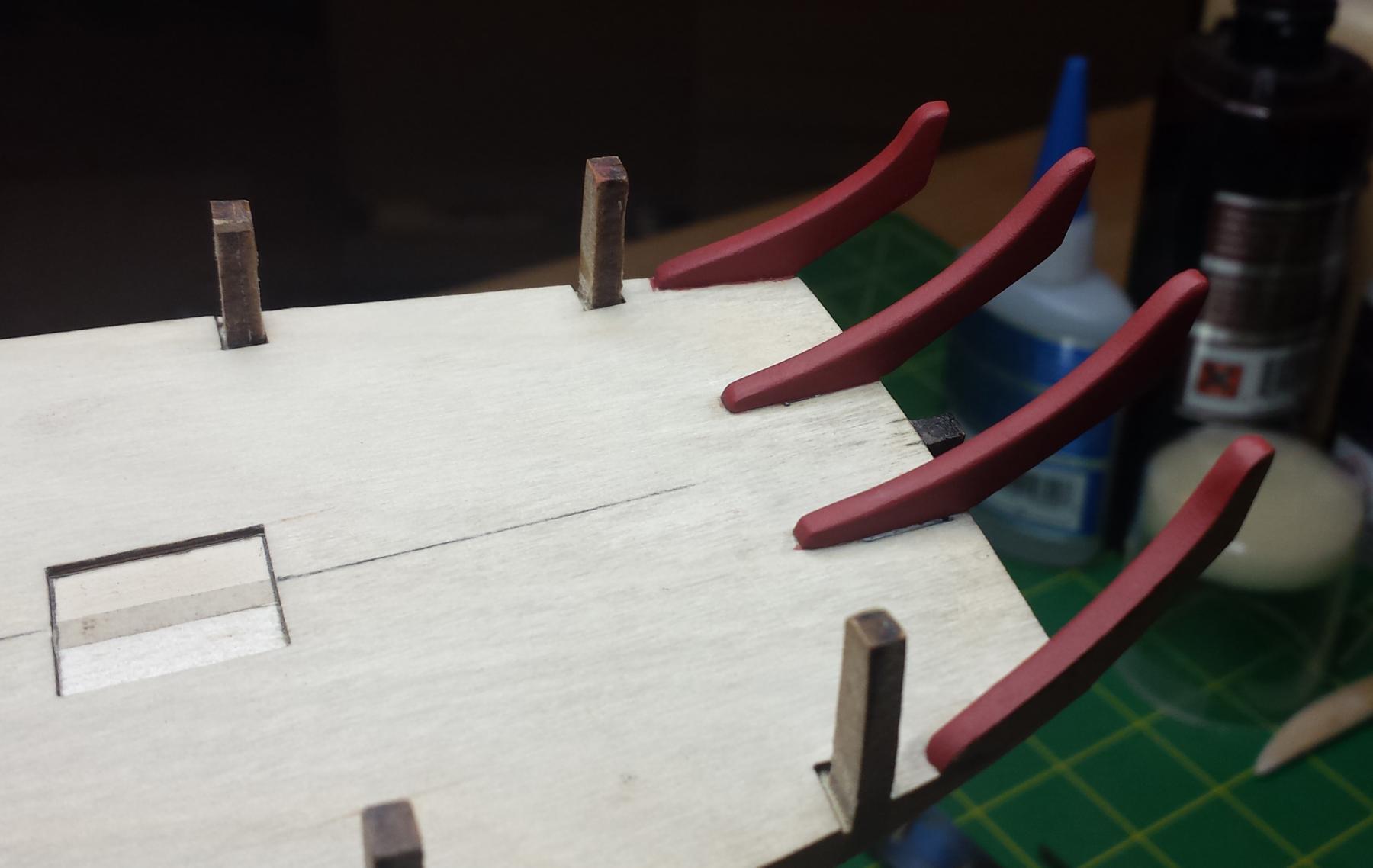
It's the fashion pieces we're talking about now, I'm about to add the upper bulwark strips that glue to the outer fashion pieces, so from here they just get more inaccessible and I decided I wanted to paint them now. First I hit them with a couple coats of a clear flat sanding sealer and smoothed down all the MDF fuzz.
Then gave it three thin coats of the Admiral red ochre.

I just wish the hue was a less orange.
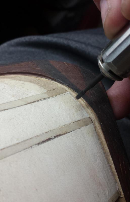
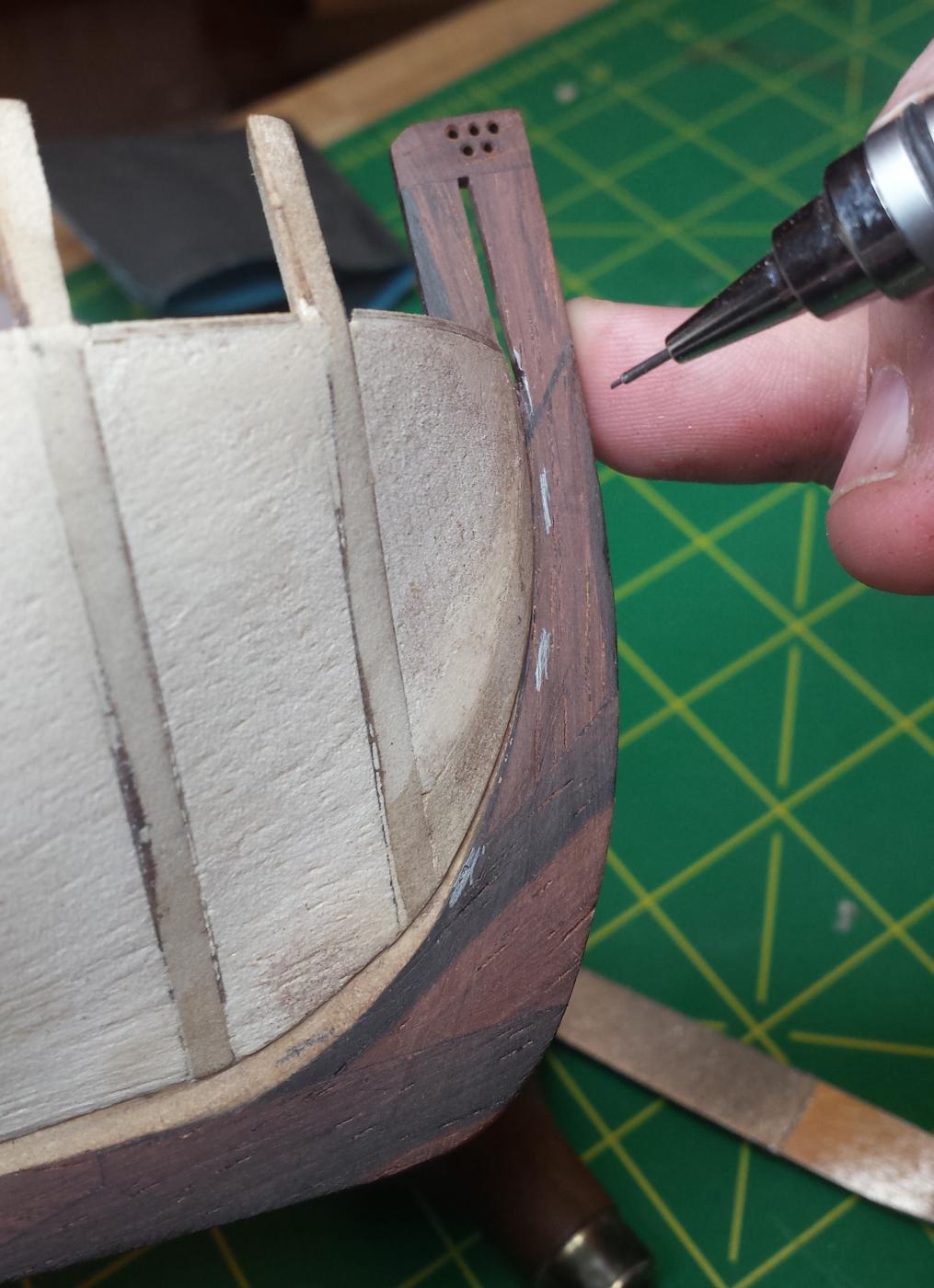
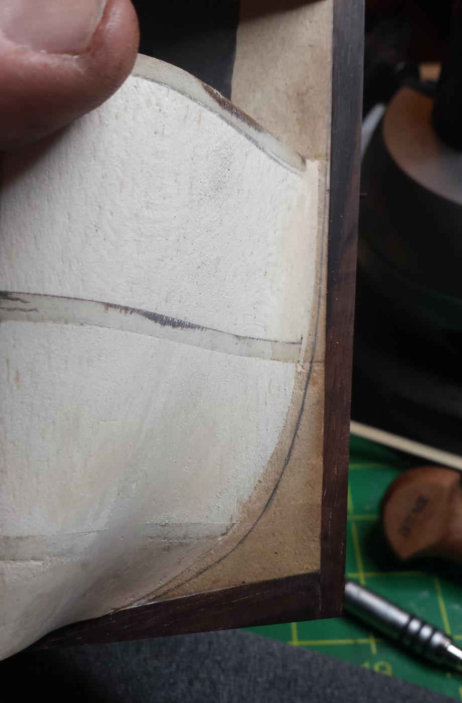
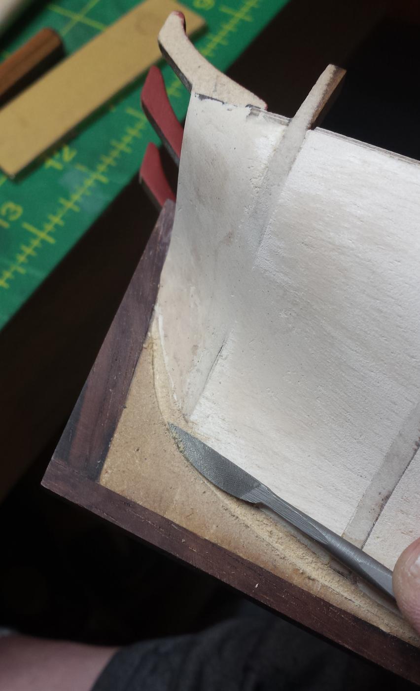
Marking rabbet. Notice my stem piece glue line was really not good on this side, not sure how but at least it's straight. Very disappointed with that, may have to fix it.


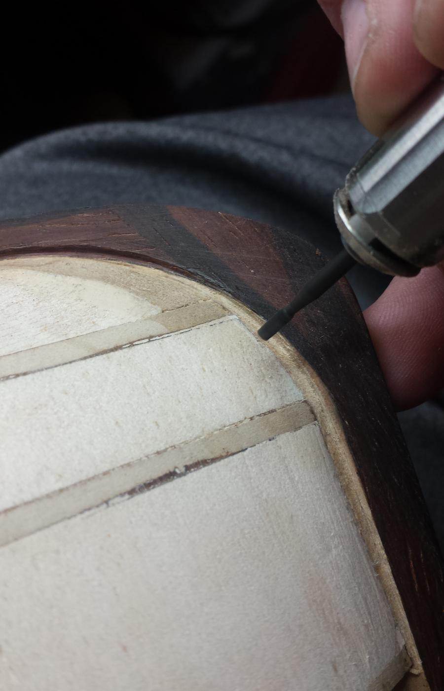
As noted tried a few tools briefly but closed in on this- a small square end mill in my Nakanishi turning at 40k RPM to rough out and just one riffler file to finish. I'm not sure I would try this with a Dremel, way too bulky and heavy with way more runout and vibration. Also this is a good quality and relatively new end mill, so there's almost no resistance from the wood allowing a very light touch.
Only trick here is having the end mill be orthogonal to the end of the frame to cut the right angle and smoothly transition between those angles along the run. I did not come anywhere close to trying to cut it in one pass, this was very light touch slowly working down with lots of shallow passes, I find this rotary tool easy to control but it's a rotary tool which means you still can completely screw up your work in zero seconds flat so slow and careful is the watchword.

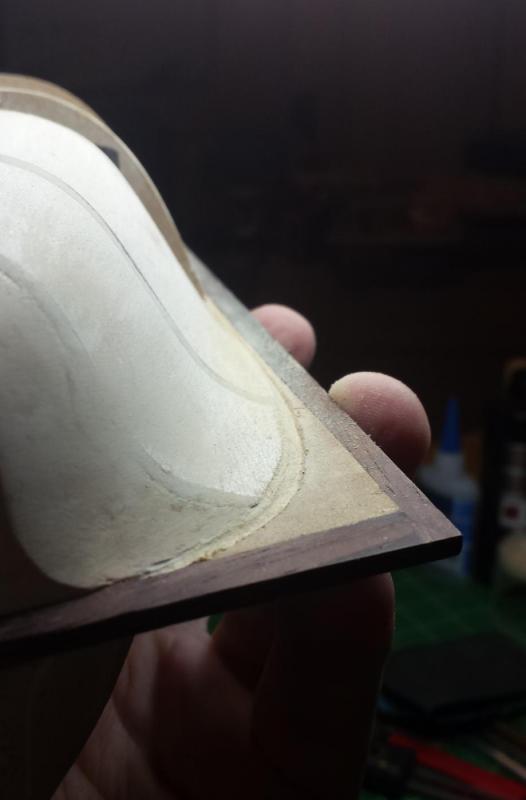
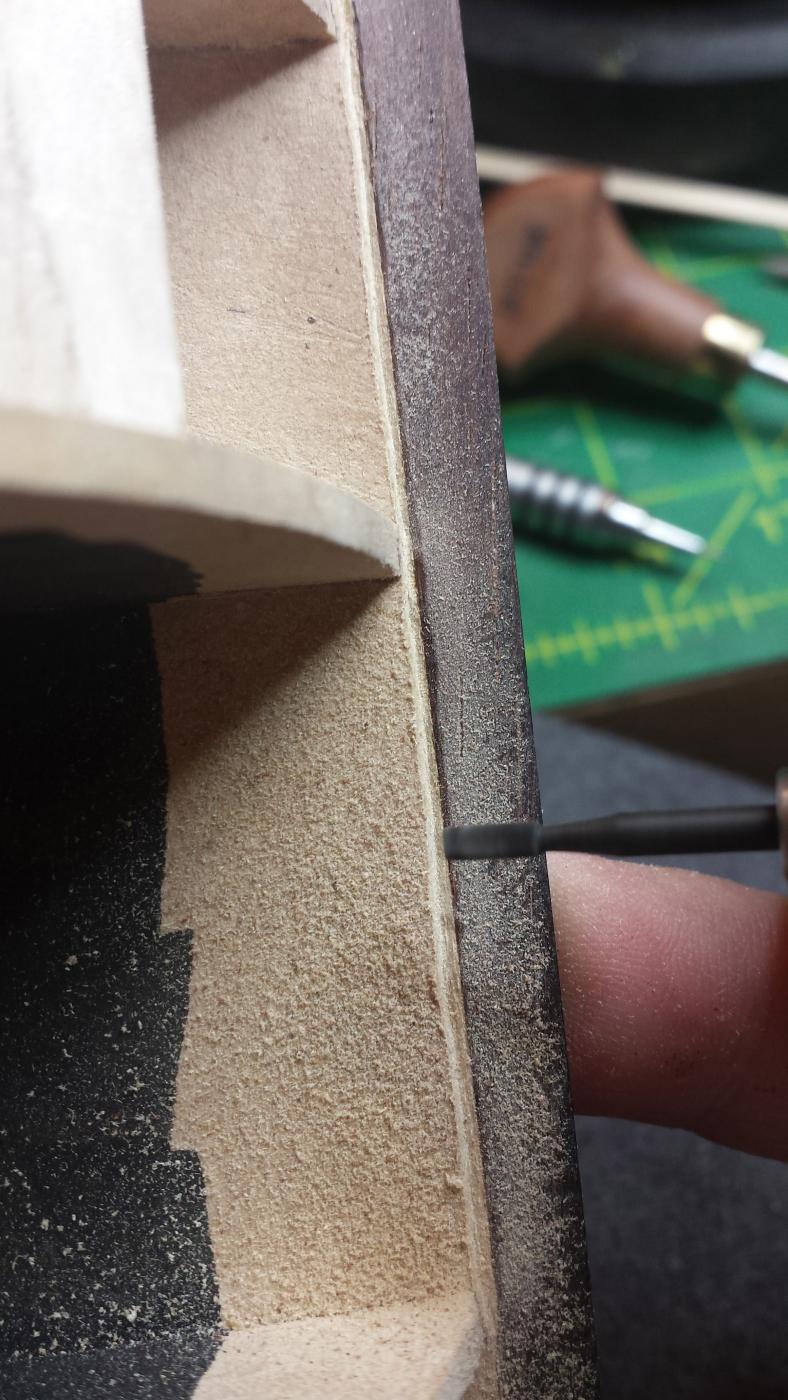
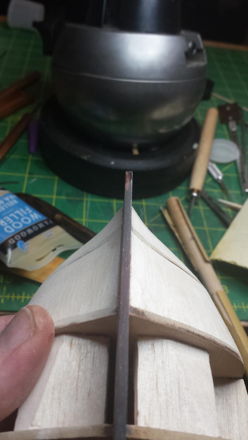
This is what the stern looked like after the rotary tool work.
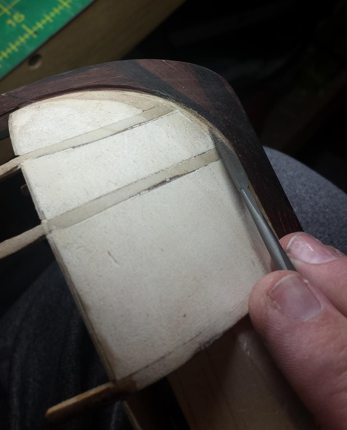
And this particular riffler file is perfect for this application. I wish I could point you to the set I have but Otto Frei has changed the Gardon-Vallorbe riffler set they carry and the choices are a bit different. My set's made by GV and was about the same expense and I will growl at you if you get close to them.
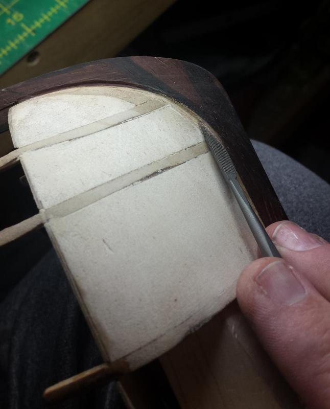

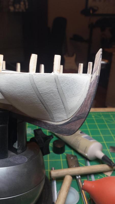
Still not perfectly straight but well within limits for first planking and I know I can make the second perfectly straight with just a bit more work.
Remember the plan is separate rabbets for each planking layer due to thin keel and thick planking, that's why the rabbet at the stern ends well short of the rudder post.
-
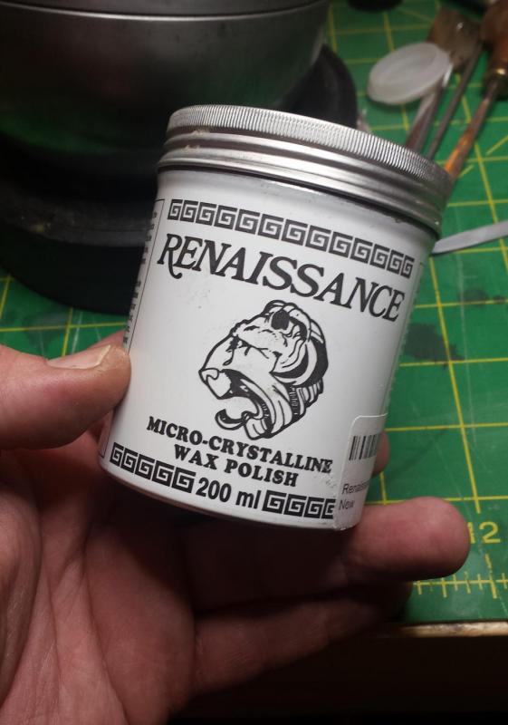
Another one, grab this wax, it's advertised as what the British Museum uses to protect its collection. I use it constantly as it's as easy to use as paste wax, but has no silicone like most paste waxes that can contaminate your woodworking area and ruin every finish you do for the rest of your life.
I use it to protect steel, for plane bottoms and anything else that needs to be slippery, and both over finishes and as the sole finish. I've been totally happy with every application. Only downside is strong thinner smell, so you need ventilation if you're covering big areas.
-
We have a good discussion of what red ochre is and where it comes from, not so clear the OP's original question was answered clearly. I have a similar issue in that I have two Admiralty Paints, crimson and red ochre. Allegedly the crimson is right for RN gunport sills and inner bulwarks, but it is an insanely bright and saturated red to my eye. I find it hard to believe they could make that red at the time, and if they could, whether it wouldn't have faded almost immediately.
I mean a modern paint manufacturer would hem and haw if you wanted to paint your house this color and have it remain color stable.
So I am considering using the red ochre, this is going to be one of the few painted surfaces on the model, most of the rest is going to be stained/clear. In the end since I'm already violating correct color by not painting some of the surfaces, I'll use the color I want but like the OP I'm wondering what the color was that they really used and what it looked like 3 months after it was last painted.
-
My question would be why, when you can have any color under the rainbow and have them be safe and stable long term by mixing alcohol-based aniline dyes? Best part is they're not pigment based, the color is molecular, so they don't occlude the underlying wood at all unless you go really dark If Gibson uses these every day to stain $4k Les Pauls in a thousand colors, it should be a good choice for ship modelers.
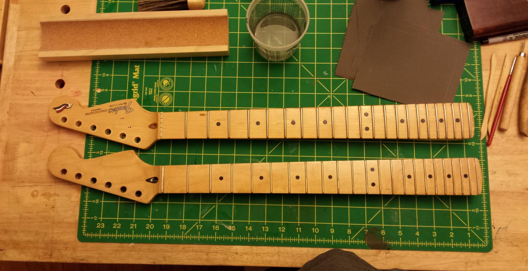
I'm new to ships but not making things, example of the trust I put in them was a so-called luthier ruined the neck on my 1994 Strat by stripping the truss rod, so I made a replacement neck and had to match the 20 year old yellowed Fender clear.

I also think they're very easy to use, best thing is to mix at 50% or 33% intended color so you can control better by putting a few coats on, and you also control color by how long you wait before wiping. With alcohol-based you can do coats about every two minutes since it dries immediately.
-
I actually thought that you'd realised that the deadeye would also require a bit of work! Maybe a request to Chuck for a "one off" would be the way to go. As for the boom/bowsprit I'm afraid I can't answer that one, hopefully Druxey or Chuck will see this and be able to answer, I'd also be interested in the reasoning behind it.
Rick
I just got a shipment from Chuck, I got one each of most of his rigging sizes and boxwood blocks and deadeyes in (I hope)the right sizes. I'll ask him.
-
I did a post on this same problem last November. Altduck recommended doing exactly what you are thinking of. I haven't gotten to the point of carving the rebate because I am still fairing the hull (and thanks to you, I'm going back and adding filler blocks as you did). I think your and Altduck's solution will work well and I intend to use it.
http://modelshipworld.com/index.php/topic/14706-problem-with-kit-planking-stock-dimensions/
I'm sorry I missed this yesterday, thanks for pointing to that. Considering the number of especially new people working on LN, we should put together a list of the oopses/WTFs?
-
-
I'm going to enjoy watching you make the corresponding 5 holed deadeye when you start rigging the ship.
Rick
The thing about deadeyes is the circle is turned so we get side grain looking at that circle, and I've never tried to turn anything in that orientation, not sure how you keep the pieces from exploding all over in the process of working them down to your circle diameter. Especially as that sounded like haha! You're screwed now you need to make the dreaded 5 HOLE DEADEYE!
-
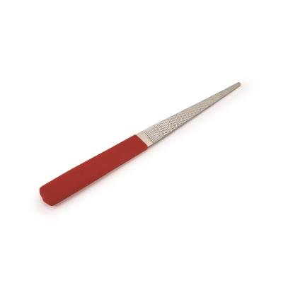
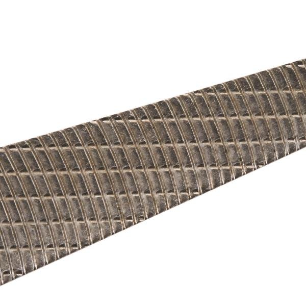
Tom, might want to try one of these (they even have one finer if this isn't fine enough) when doing the masts on the lathe. I haven't used them for specifically this purpose, but I have a different Iwasaki file and have used it very successfully for similar things. Unlike normal files, these teeth are milled with some kind of fly cutter in a circle the center point of which is maybe a foot beyond the handle of the file. So the teeth are also curved forward, and this file properly used will take shavings instead of dust and I'm guessing a fine or extra fine might leave a polished-looking surface much better than sandpaper unless you go out to like 2500 grit.
Iwasaki 8" Extra Fine Side Float
-
-
I figured out that it meant .6mm. No idea how, but I did.
Anyway that stem piece took way longer than I thought it would, but it's done. And for some reason took lots of photos so you get to see every step.
First I said in the previous update that I'd used lots of filler to get a reasonable shape at the stern, but forgot to show what I mean - as you see for me at least, the edges of that bulkhead were completely covered and as I said that bulkhead needs to be at least 1/8" talleer for it to be correctly faired where planks would touch the entire edge.

And another miscellaneous thing, this stuff is great. Advertised as the product the British Museum uses to preserve its collection. I use it constantly. It's what I use on all my tools, both handles and to preserve the steel and for plane bottoms. I've also used it over wood finishes or as the only finish on wood and I always like the results.
Unlike most paste waxes it has no silicone so you can use it in your wood shop without silicone contamination screwing up every finish you do for the rest of your life.
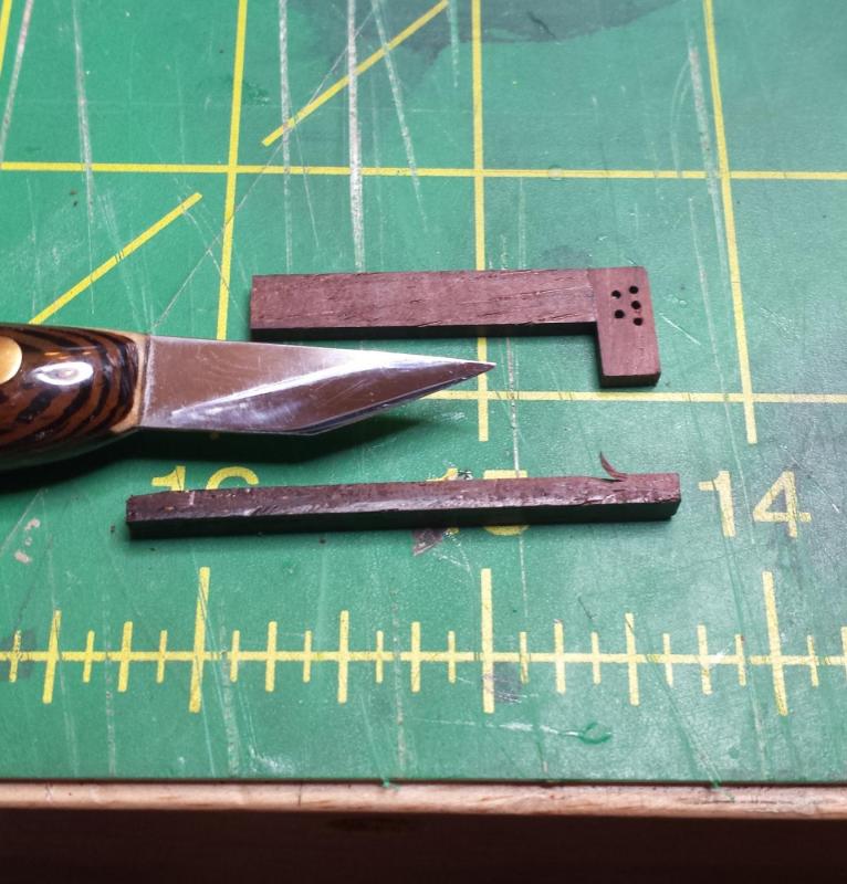
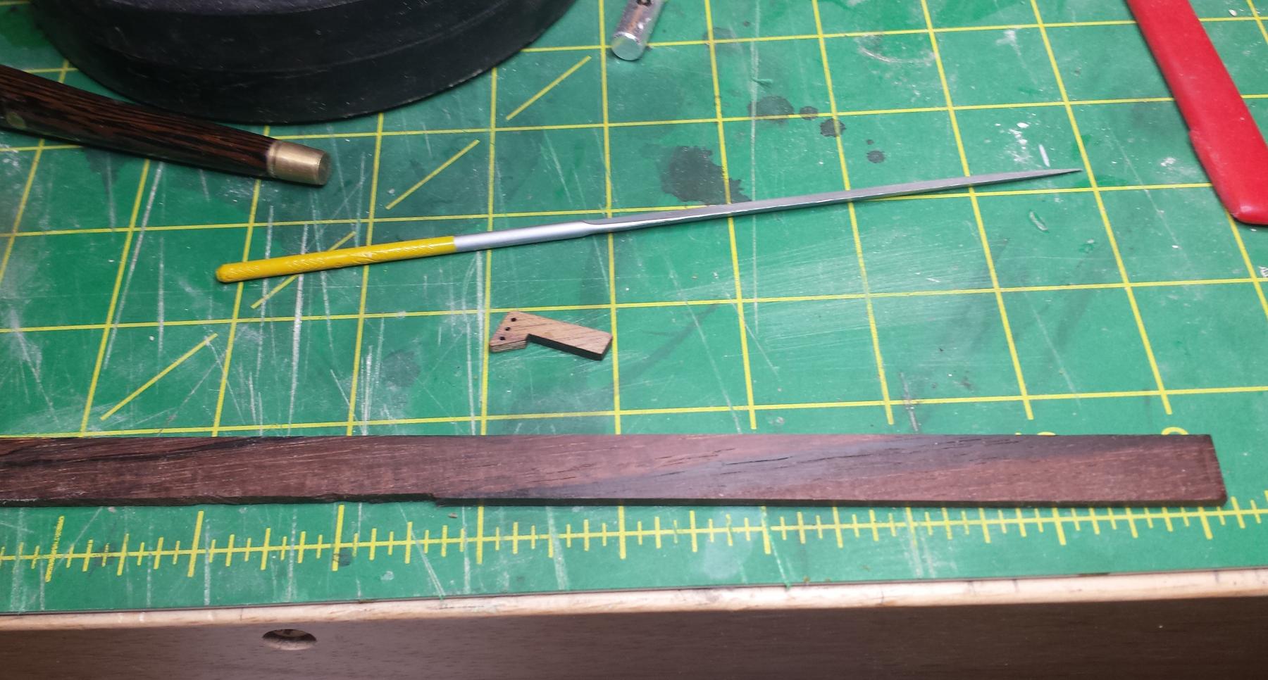
Ok so the little walnut bit is what we need to replace along with another piece going where the mitre-looking edge is, so I grabbed one of the other cocobolo strips I planed down other day.

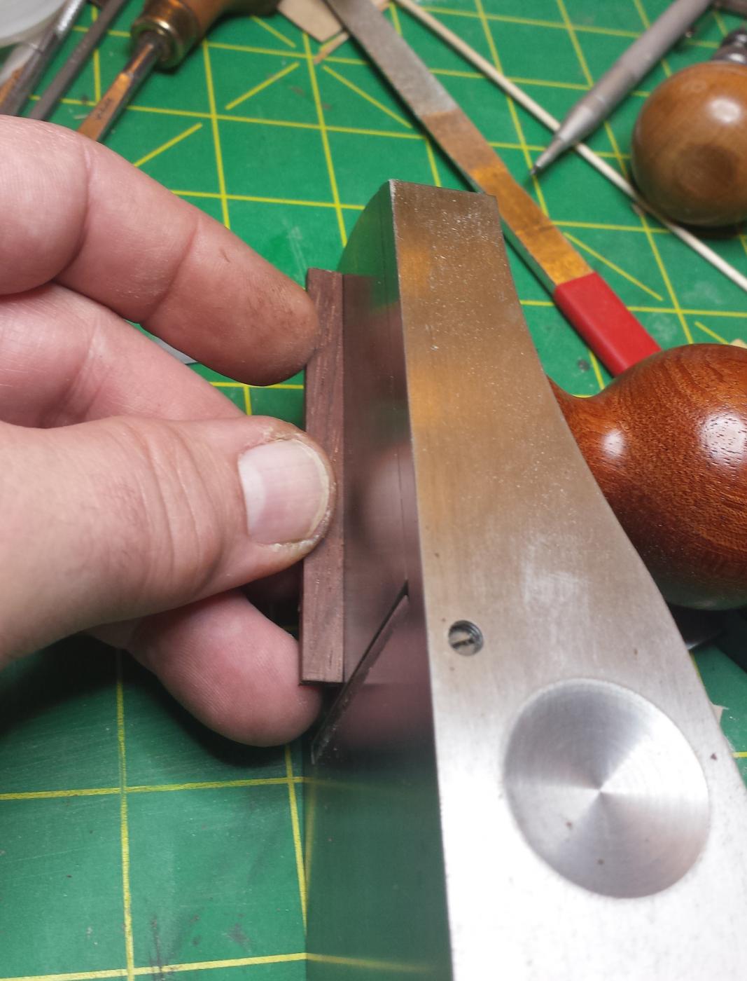
I cut a piece from that strip long enough to make the all of the pieces I need. Here is another reason it's good to have sharp full-sized planes around, they make it trivial and quick to get a perfectly square and straight and clean edge.

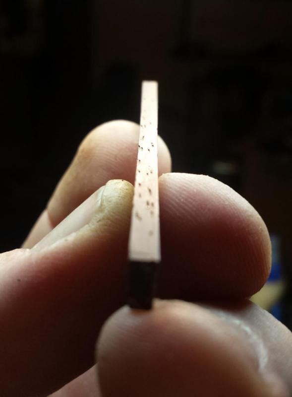
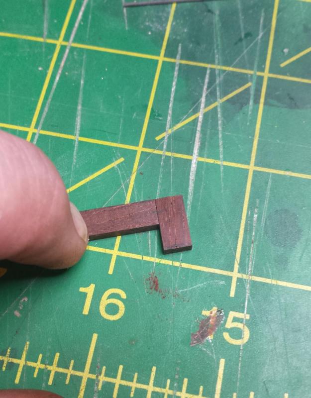
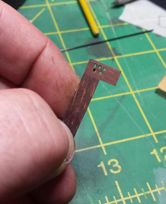
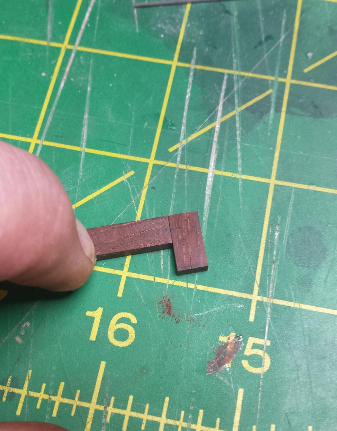
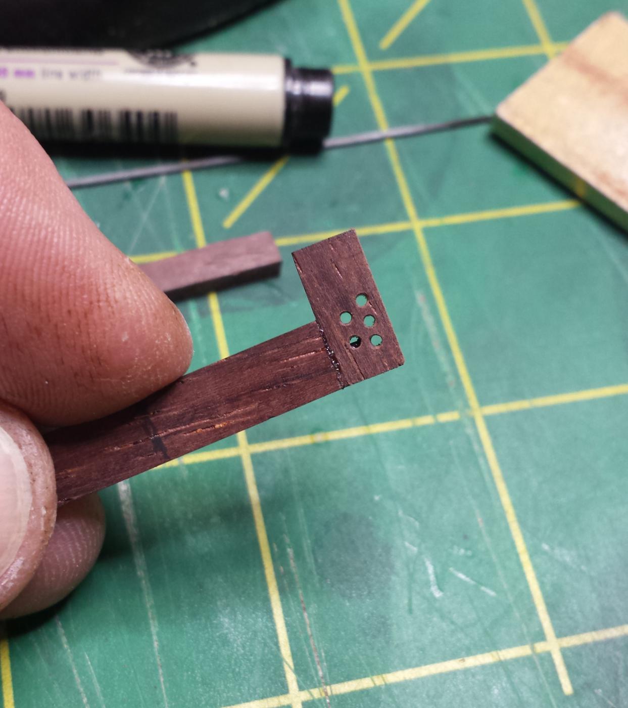
First two pieces, marked to get drilled for carbon fiber pins.
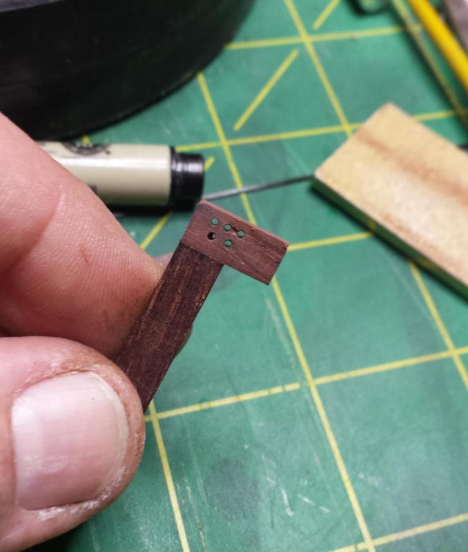
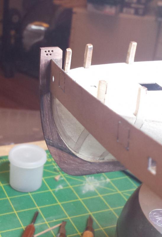
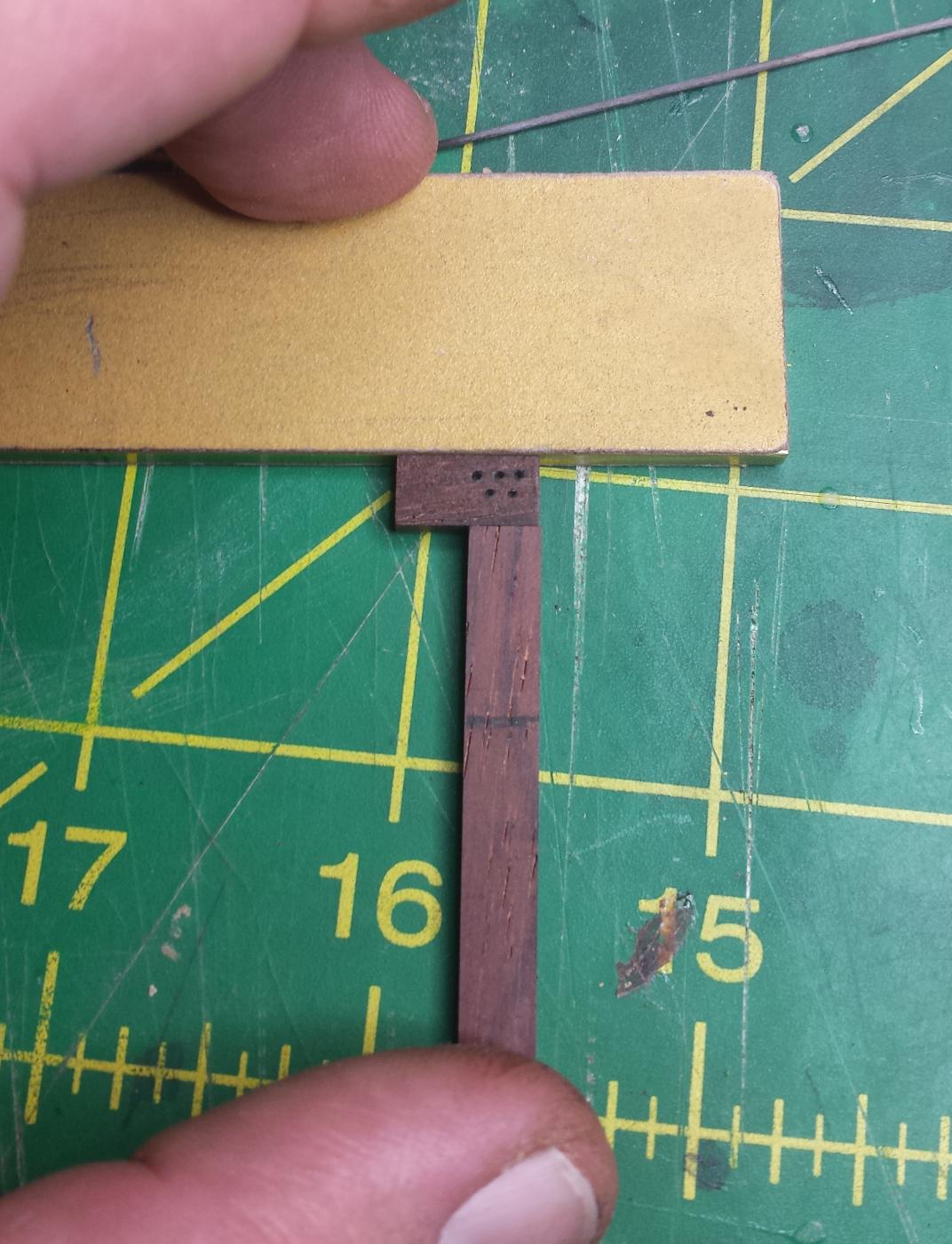
Before I could glue them together though, had to drill the five holes (thanks for pointing that out Rick) holes for the deadeye connected to the forestay. I then took a 90 degree stone-setting bur and beveled the holes as I assume the real ones were, no way they'd run an important standing rigging element over a sharp corner. I just held the bur in my hands, it's a good quality jeweler's bur so it's sharp and just a little pressure and a few spins is enough.
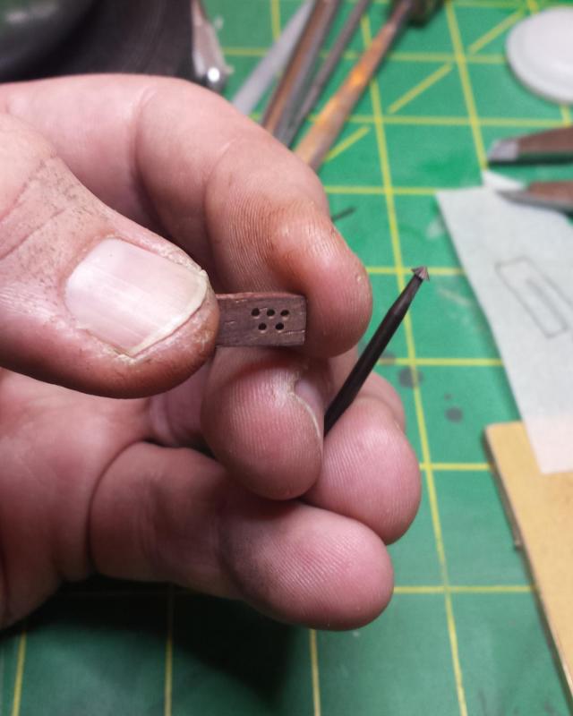
Now with 500% more holes.

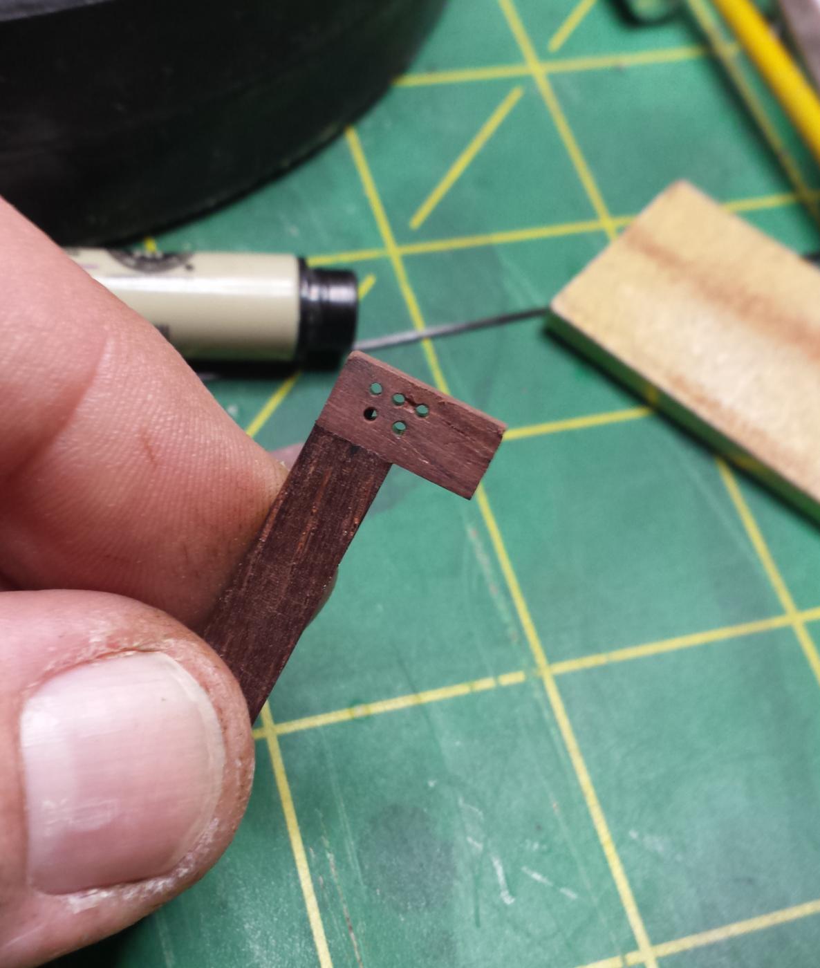
Glued.

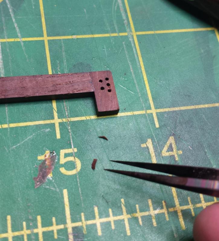
Unfortunately we have a problem, wood blew out between upper right two holes on this side. Which is annoying since it was drilled with another cocobolo piece backing it. Have to fix it, too obvious.
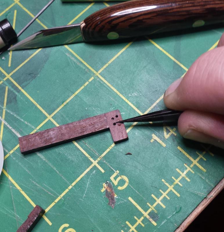
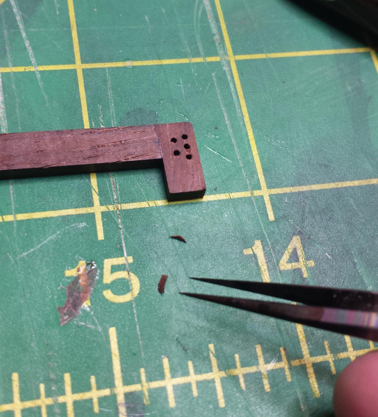
Step 1 curl a little shaving up off another piece.
Cut it off, grab our fine tweezers with the carbon coating that makes them very grippy.
Use tweezers to place on glue and hold down.
Sand down, all fixed.
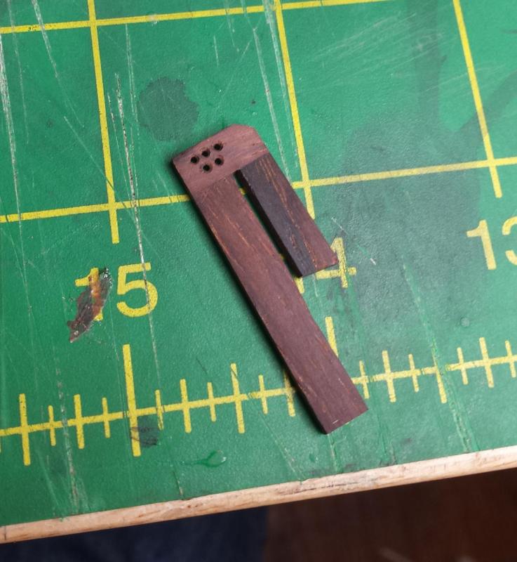
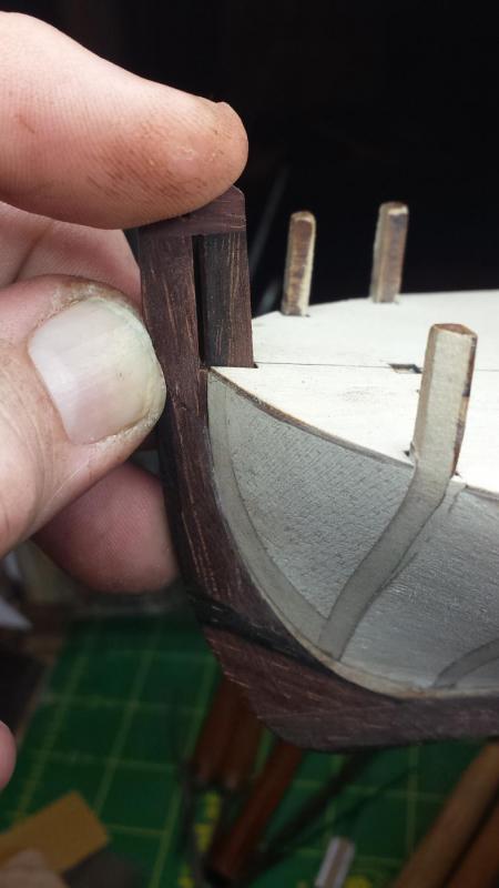
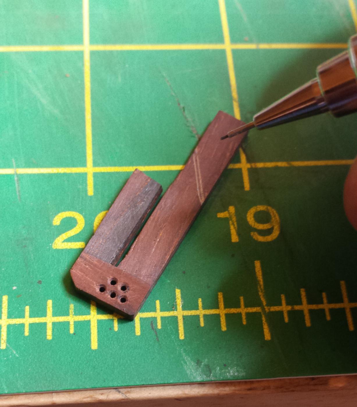
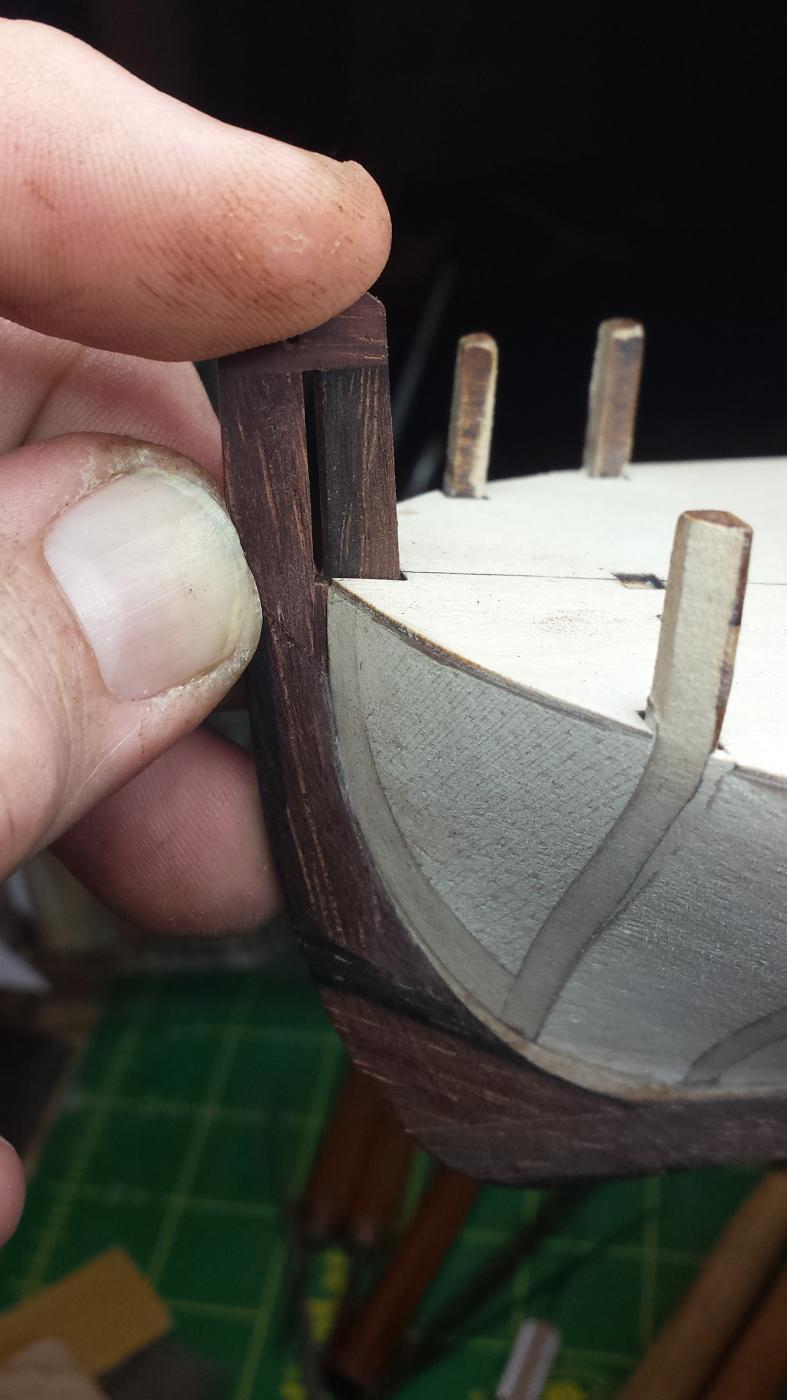
Here I've made the third piece and am test fitting it with the upper bulkhead strip that has to fit into this piece. You can see I have to trim the inside a bit, groove still not wide enough.
Once that was fit, put my CF pins in and glued and cleaned up the third piece.
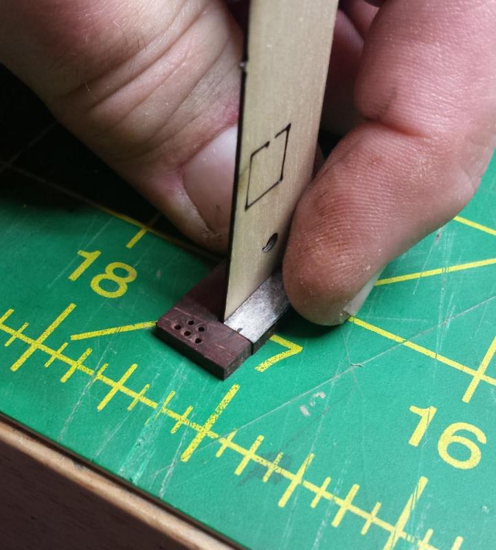
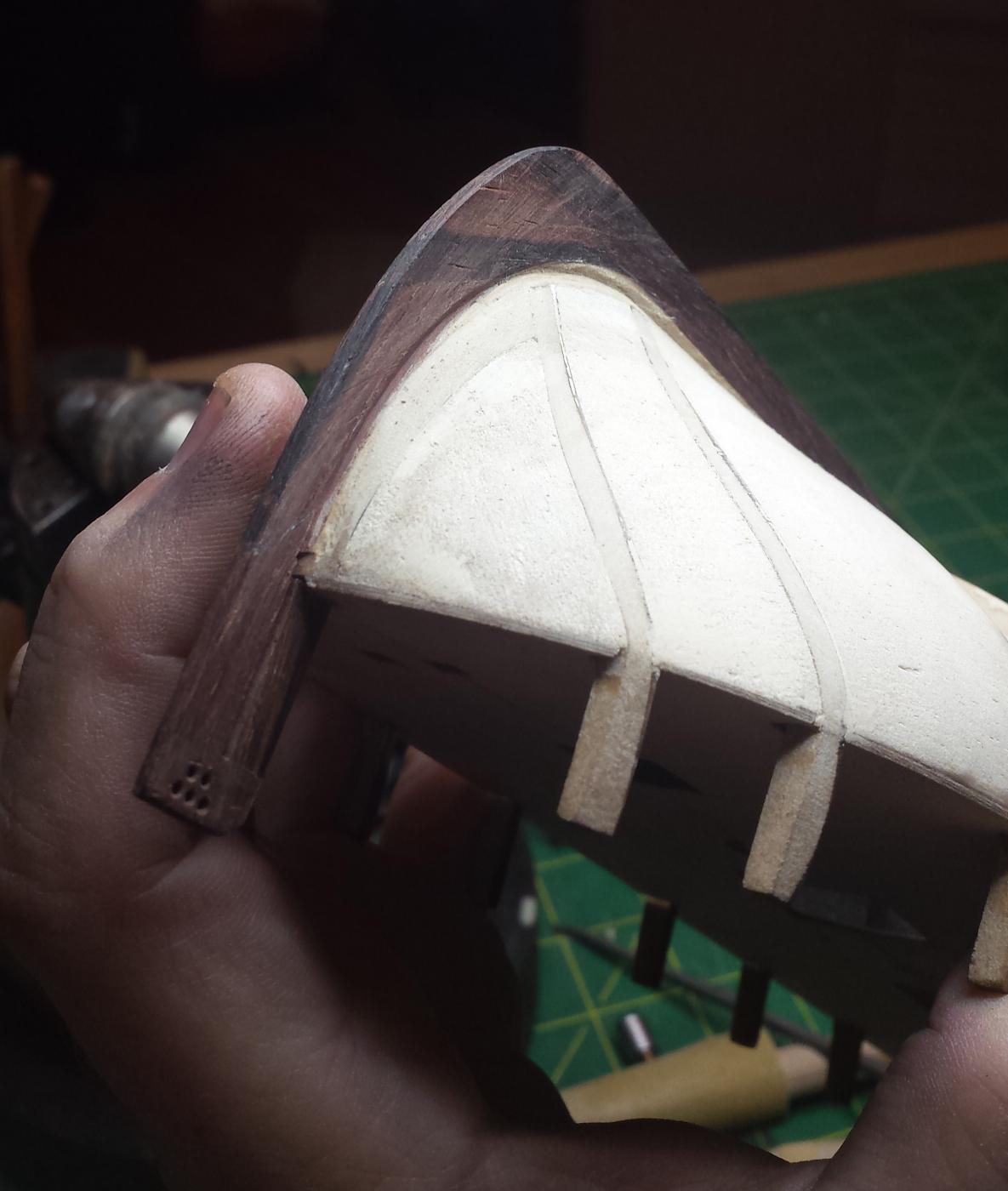
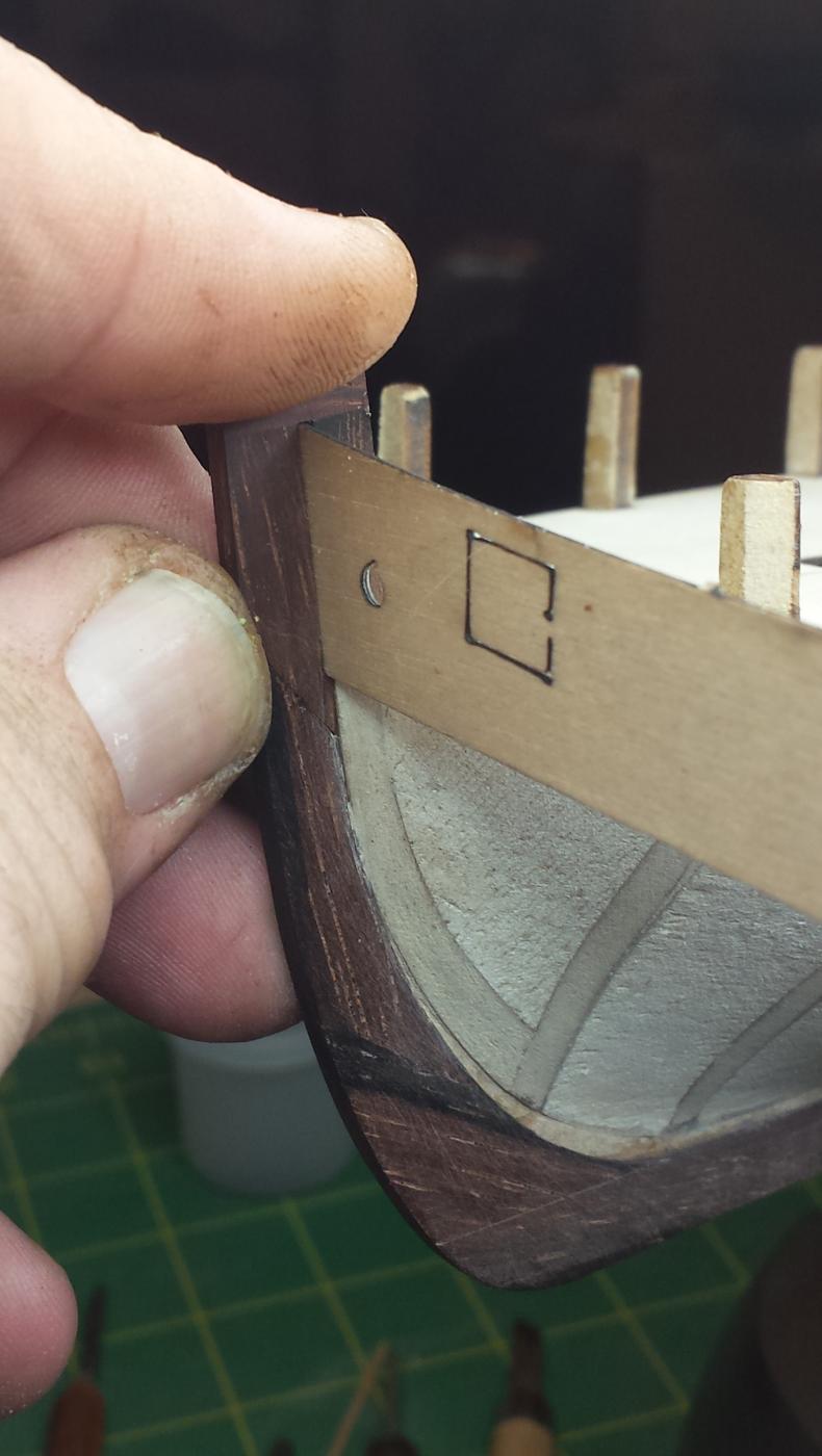
Now we have to fit this to the ship and the stem ending that is at an angle, marking for the rough cut.

We have a good fit. The big gap between it and hull is intentional, it was easier to make it this way and glue a piece on than trying to cut a big notch in a cocobolo piece.
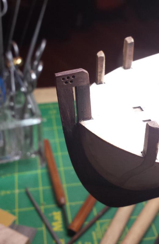
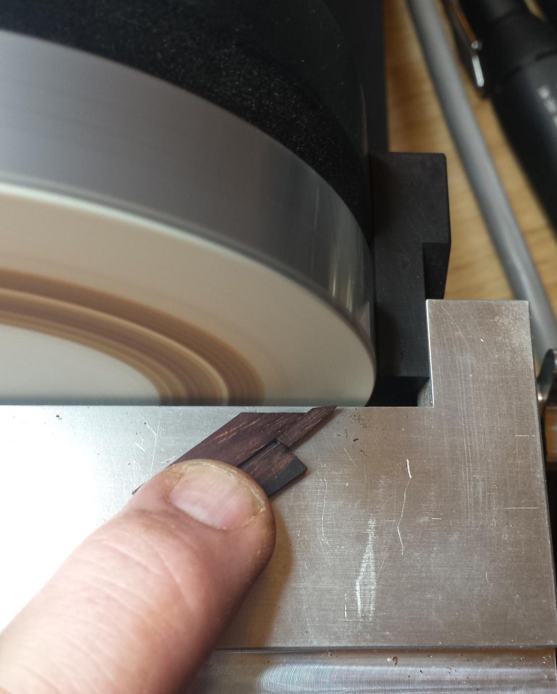
After I added the little extra piece I needed, I flushed it with the other piece on the disc sander.

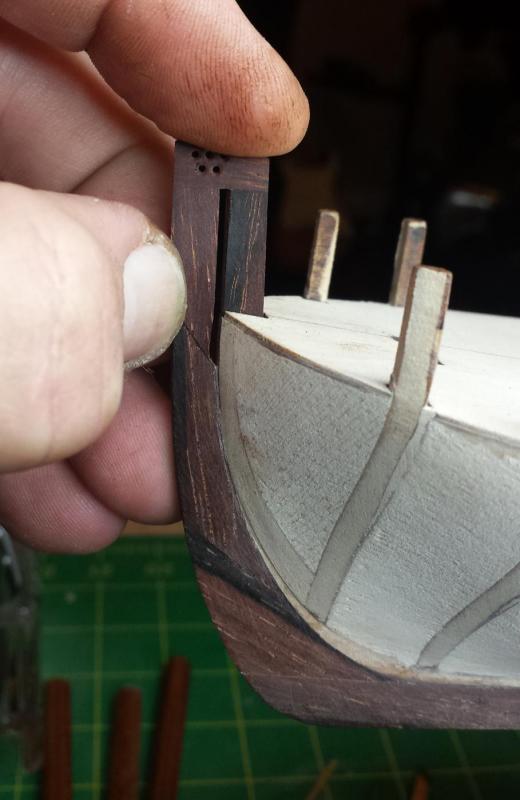
Fit looks good now.
Test fit with bulkhead strip.

And now glued and cleaned up.
-
I understand, same thing happens with Kiwi and Hoser history too, gets overrun by British history.We Australians get a little upset at times when our own history gets forgotten. The original release of this ship did in fact claim it was the real "Lady Nelson" - pretty obviously not when you count the masts!!
As to the planking, your idea looks fine, I did go about it a slightly different way in that my second planking was done using .06 thick planking - somewhat easier to manipulate.
Rick
Thanks for the confirmation on the plan. And yeah, another idea is to say screw these thicknesses and redo much thinner, .6mm would be about right. One wildcard is that I haven't received my crown timber order yet that includes boxwood outer planking so I don't know how thick it is.
-
-
I fitted the gunwales first then soaked and bent the transom into the approximate curve needed. Once I was satisfied with it I then started carefully shaving the "legs" until everything went together neatly. By the way the gunwales have a tendency to break at the bow gun ports if you're not super careful when fitting ( not that I'd expect anything other than care going on your build so far).
Rick
The plankling is really confusing me at the stern in that I can't understand how the kit instructions are supposed to work out correctly. You're supposed to put two layers of planking on each side of the deadwood going into the rudder post, which = 4 x .047" fitting flush with a piece that's .115" wide. Not only would you have to remove the entire deadwood you'd be running planks from one side against planks from the other.
My plan, and in the spirit of trying not to solve every problem myself, please tell me if I am smoking crack. is that I will have two bearding lines and two rabbets at that end. The first bearding line is basically what I have now, and I'm going to make the rabbet for the first run to stop as far short of the rudder post as possible and I'm going to fair the first layer into the current false keel surface. Then we'll work from that second bearding line to cut a .040" or so deep second rabbet up against the rudder post.
I'm not seeing any major issues on the rest of the hull, except that the width of the keel at the very top of the stem becomes really narrow with two layers of planking eating up the available space. And also the twist that needs to be put in the wales planks are about 70 degrees, which should be interesting.
I also need to stop on the planking to remake the top piece of the stem in cocobolo and I'm making it in three parts so it will be much much stronger. Hopefully that will give enough time for you guys to report back on my crack-smoking status.
-
Vossiewulf - there is another reason why a few of us don't really like the name on this cutter. There actually was a "Lady Nelson" used in the exploration of Australia but rigged as a brig rather than a cutter see https://en.wikipedia.org/wiki/HMS_Lady_Nelson_(1798)wikipedia I know but in this instance basically accurate.
Rick
Yep, I was aware of that ship too but not that people wanted to defend its honor
-
One thing you might consider for future builds is that quite a few don't put the stem, keel and sternpost on until the first (or even the second) planking is done (at least in this kind of double-planked kit). That way you avoid damaging those parts, the sanding of the bearding line is easier, and you can figure out the rabbet more easily. I too didn't learn that until after the fact!
I don't know the extent to which the Lady Nelson builds are similar to the Sherbournes, but the approaches to the transom on the Sherbournes was very variable. I'm not sure that the curvature needs to be the same across the whole width, but which ever way you do it bevelling is going to be part of it.
Tony
That was my original plan, but the kit calls for the keel to be installed since it has that weird U-shaped piece up front that is needed to retain the upper bulkhead strip that is the first piece (according to the kit) to be installed in the planking process, and they want you to work down from the top.
Even so, if I had it to do again I'd probably figure out a way to make a temporary piece to hold the bulkhead strips and leave the keel off until the end.
-
One specific error in Petersson is the anchor cable on the windlass. The cable on one side is correctly led over the drum whilst the other one goes under. So turning the windlass will be lowering one anchor whilst raising the other ! This error has been replicated by the manufacturer of the model of HM Cutter Mermaid .
Rick
I was laughing thinking about that, it would be perfect for a sailing comic - show ship from outside with that happening and a text bubble above with "uh, Captain?"
-
I am building the LN myself and have been pondering the name issue. The historically accurate "generic cutter from the 1800s" certainly lacks glamour and wouldn't fit well on the transom. In thinking about this, I concluded that if you asked Lord Nelson himself what name he would prefer, it would be Emma. At the risk of being irreverent, that is what I have named her.
Sorry, Mrs. Hamilton, no disrespect intended.
Well that's an amusing way to solve the naming issue, I was thinking also that that seemed to be a name that wouldn't exactly thrill the one-armed guy.
-
Hull is now fully prepped as far as I can tell, all I need to do is cut the rabbet for the first layer of planking and then add the upper bulkhead strips and start bending wood. This is someplace I have to go back and read Mr. Underhill I think, but as far as I can tell I'll need separate rabbets for the first and second layer of planking, the first stopping well short of the rudder post. It would pretty much have to since two layers of that planking are .090" when the whole rudder post that started as .125" and is now about .115" after level sanding (I was fine with that, only lose .002 final sanding). And 2 x .090" > .115" if I remember my arthimetic.
Or not cut a rabbet at all for the first layer and just bevel the ends but I don't see how that doesn't result in planks popping out in the long run.
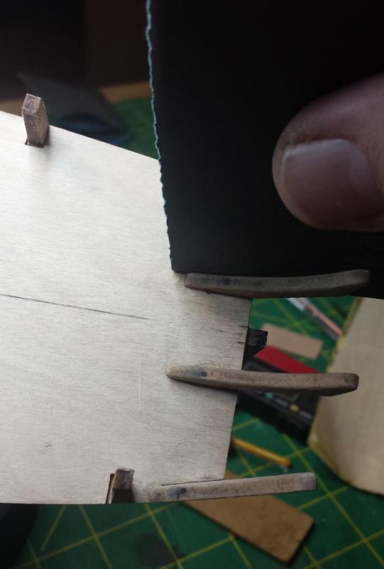
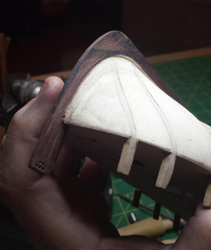
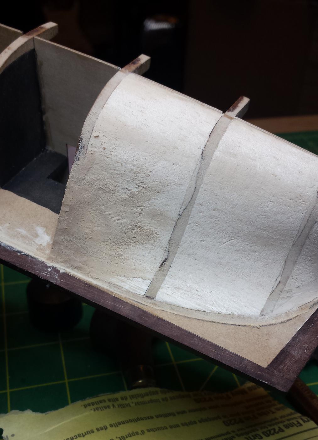
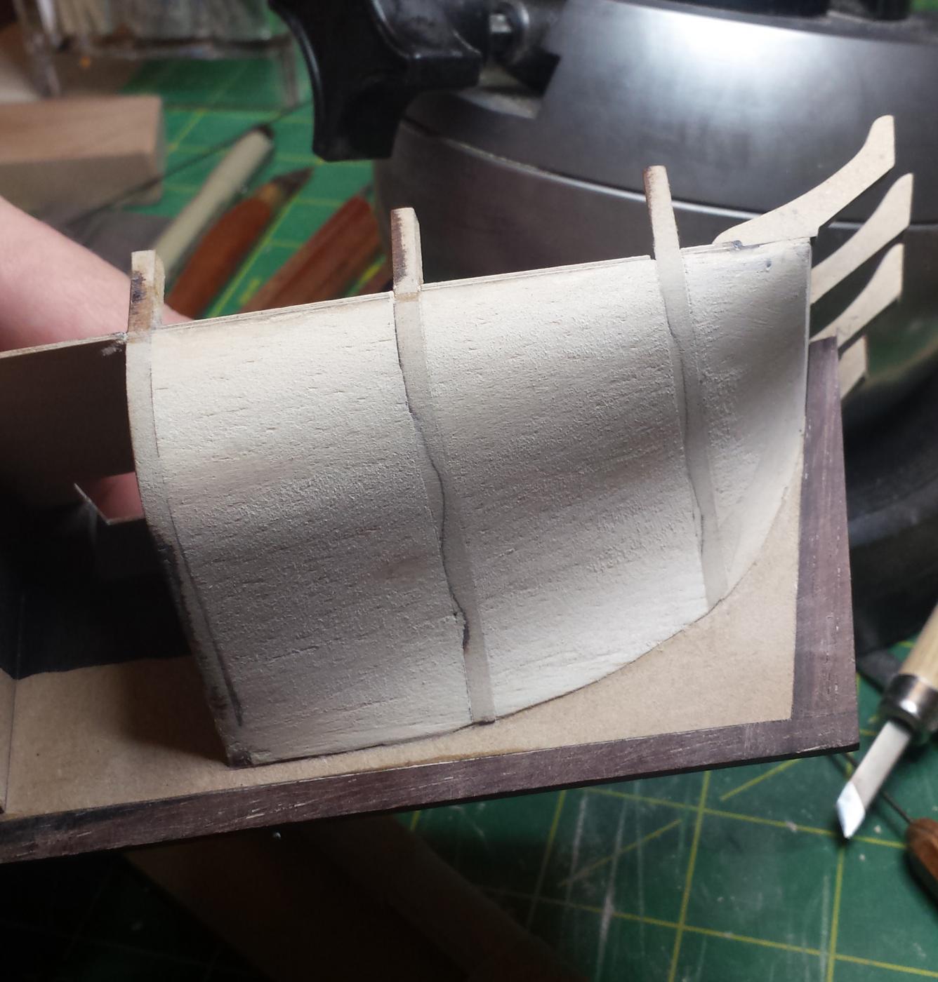
Anyway, I had left hull in the just short of done state. In particular upper bulkhead stanchion things have hardly been hit.
And here we are after rough sanding.
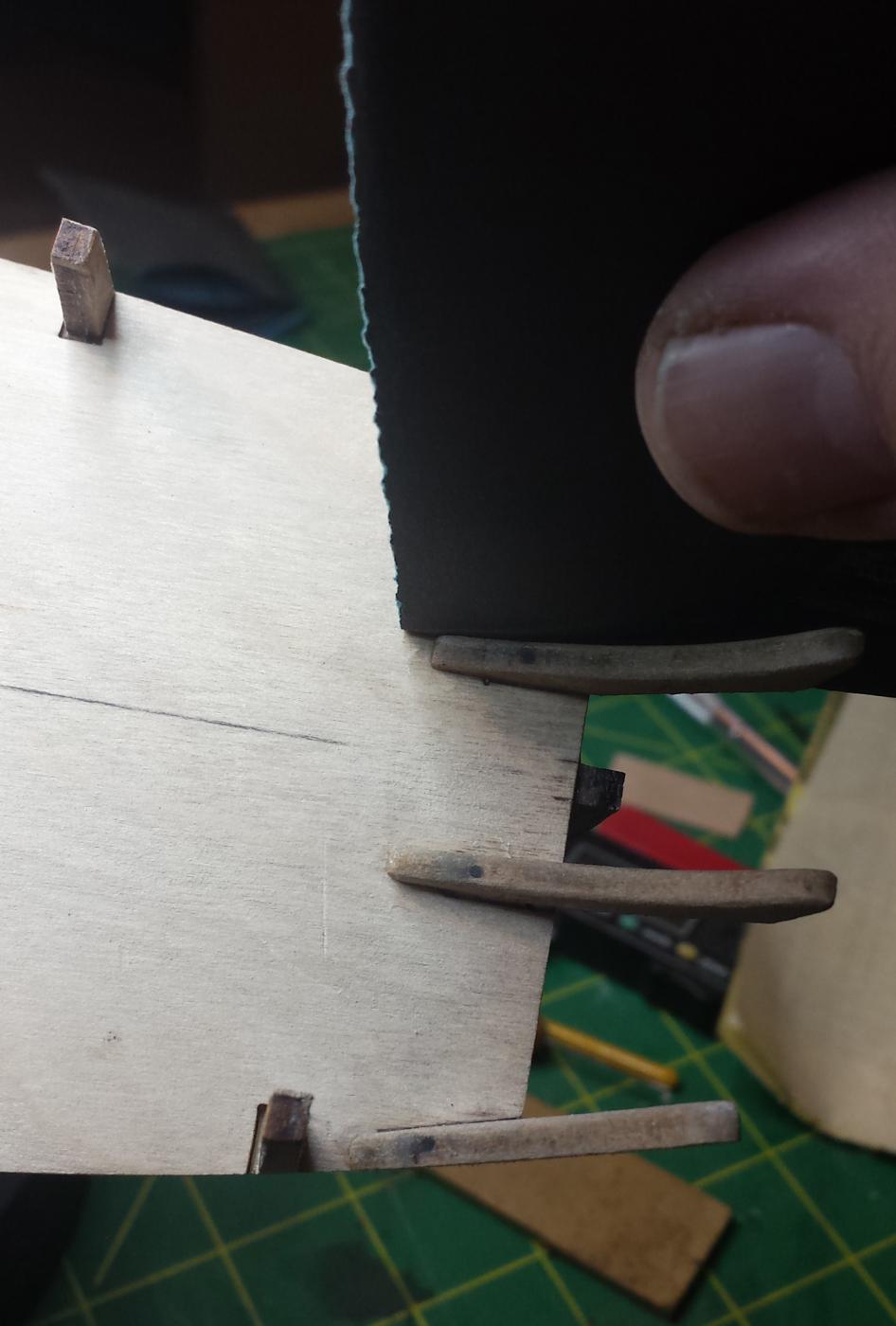
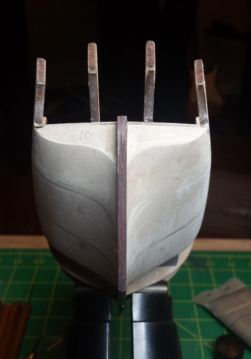
Checking tops of stanchion things to verify symmetry.
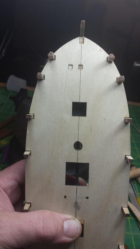
Bow and stern bulkhead symmetry.
 .
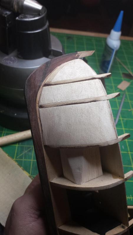
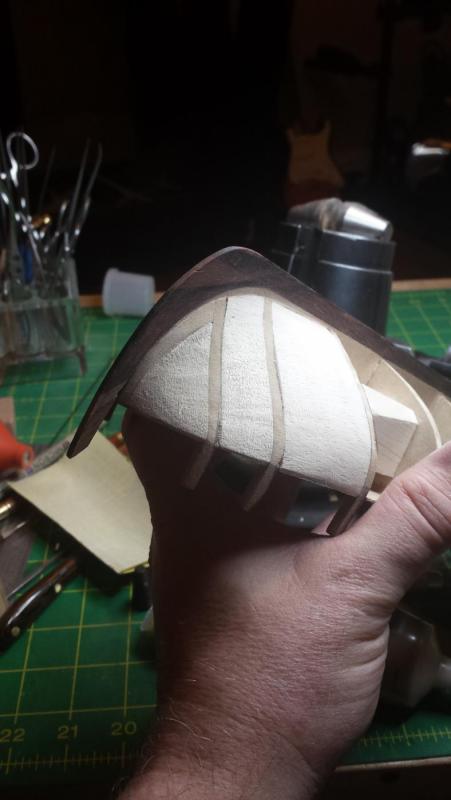
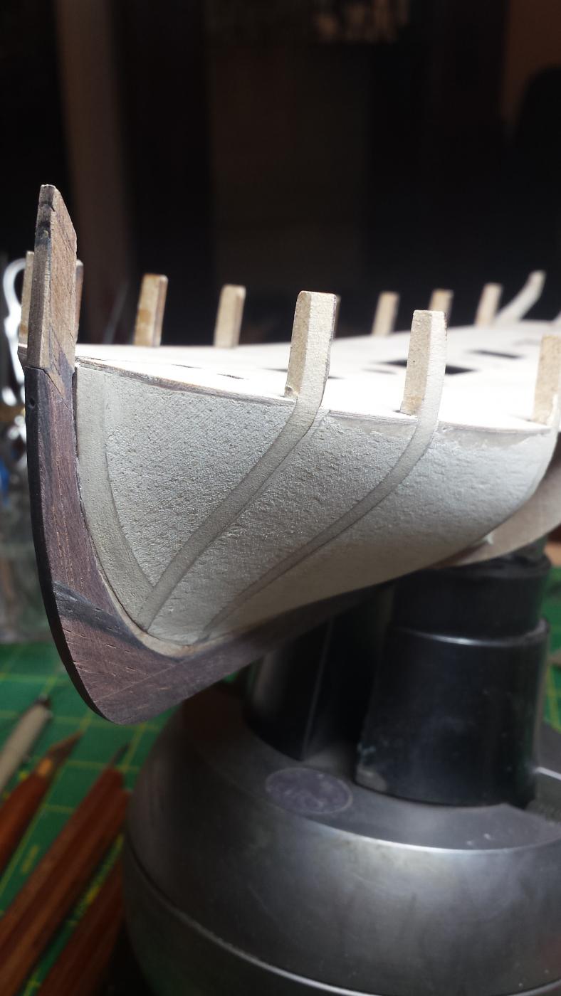
.I then hit it with Famo Wood filler for the last gaps, this was really needed on the stern just short of the counter... no it's not the counter it has some other name I can't remember, last frame before the overhanging stern part starts. Anyway the vertical turn there is severe and that bulkhead should be much taller to allow contouring the full edge surface, I only got to about halfway before I decided I wasn't taking that bulkhead down any farther as it was looking plenty small already. Even here the turn from the builkheads to the hull planking seems very severe.
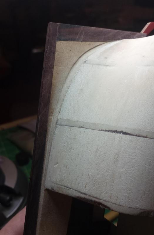
Here are bow and stern both sides after final sanding.


Overall I'm ok with it as long as I can figure out the rabbet correctly.
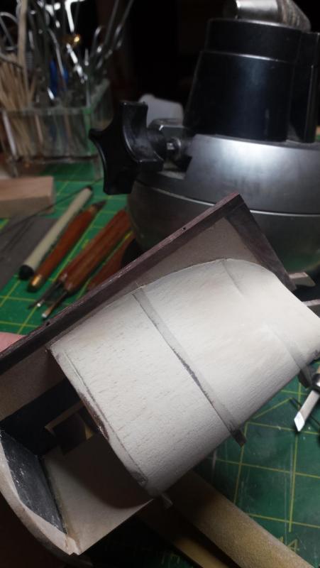
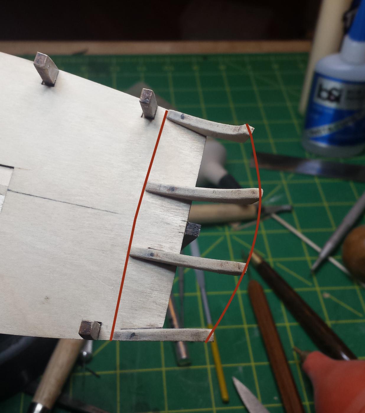
One other concern is this, these pieces are aligned correctly and are aligned with each other in the front (slight curve from this angle), but the stern ends seem to need much more curvature for full-width bevel than the kit pics show, and only way to reduce it will be to remove material from the center ones.

And since I need to think on two things (rabbet and stern) I called it an evening there.


Lady Nelson by vossiewulf - Amati/Victory Models - 1:64
in - Kit build logs for subjects built from 1801 - 1850
Posted
Thanks Pat. And Rick yes, good point, it could have been worse Hardly tragic anyway, will fix it this evening and hope to get the bulkhead strips installed at least.