


Jond
-
Posts
759 -
Joined
-
Last visited
Content Type
Profiles
Forums
Gallery
Events
Posts posted by Jond
-
-
3 the hull framing
I first, scanned the line drawing, embedded it into 2d cad, scaled, and then traced bulk heads. I chose to do this hull only as bulk heads because the affect I think is to have the unusual white hull and flying sails as the chosen image. I then scanned the Keelson on three images and embedded them in a 2d Turbocad drawing, then aligned and scaled them. Unfortunately, when I first did this, I was following the note by Howard Chapelle on the drawing that made it (148ft at the rail). Fortunately I re-read the NJR article mentioned above and learned that the best approach would be to shorten the vessel to 133.5 FT at the rail. Thank goodness for cad scaling.
-
1
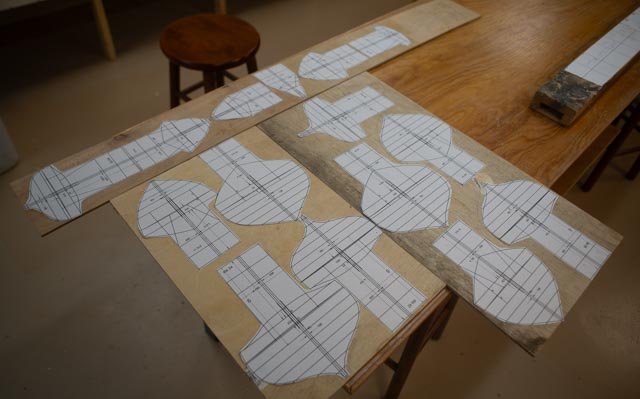 Here are the stations all cut out and glued to luan plywood ready to cut.
-
2
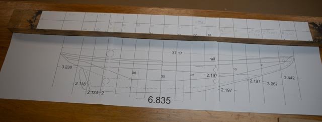 Here we see the keelson assemble drawing and building board ready to go at 148 feet
-
3
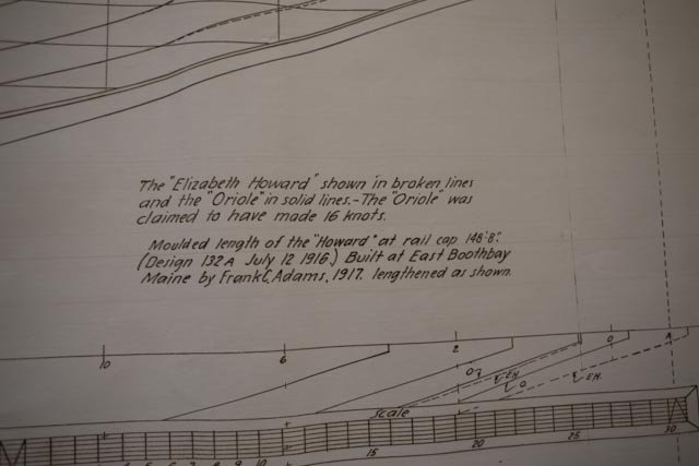 here is the Chapelle note that set us on the path to 148 ft.
-
4.
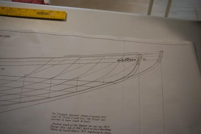 here are the dotted lines that extend the bow all above the waterline. Purely for speed, I am sure. Later measuring this extension, as in the article it is 6.5 feet.
-
5
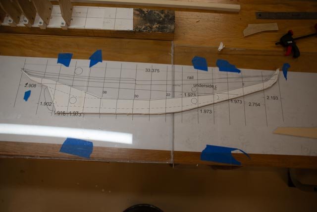
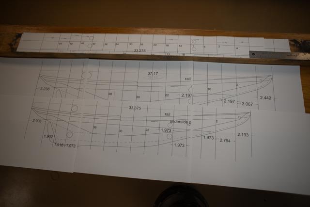 here is the rescaled keelson assembly. I remade the building board template on the same drawing.
Now the first cutting
-
6
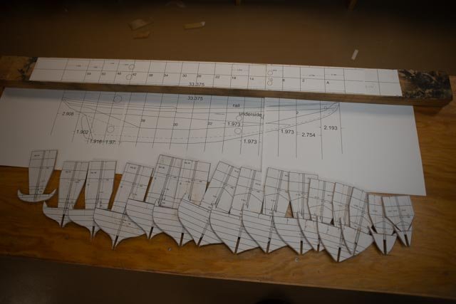 Here are the bulkhead templates cut out
-
7
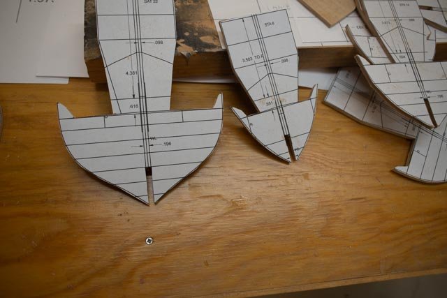 In this view we see the raised portion to support bulwark planking up to the rail. I struggled with this detail on my last build [ it was at smaller 1:96 scale] to remove these “tabs” after the planking. Since these must be removed to allow continuous stanchions at each frame[ 4 per bulkhead], as seen in the in the photo I found, I have decided to remove these tabs now and then add stanchions later. We’ll see if it’s a better way to go .
-
8
 here I am doing something new as well. I chose to laminate the keelson assemble with three layers of basswood. I used solid maple last time. My reason was here there is more sheer to the assembly, so there will be three full joints. The overlapping allows a stronger joint both forward and aft.
-
9
 Here after cutting out the keelson assembly one can see the considerable shear in this design. A butt joint would not have worked well. The other reason is the width of the keel in the section drawing is only 3/16 [10in} where other heavy fishing schooner keels were ¼ “ [12-14 inches.]. this keel projectys further below the hull than other schooners. We will address again later.
-
10-11
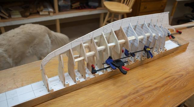
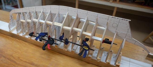
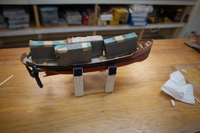
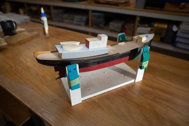
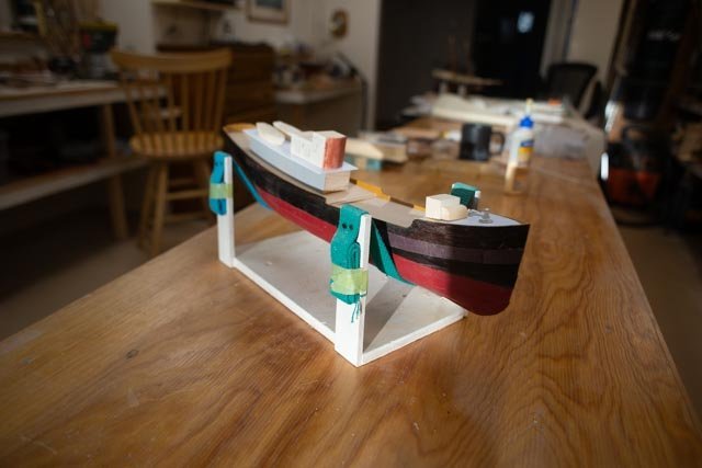
- Here are progress images of a rough first dry fit as I approach the end of this phase.
Next up will be to complete the frame and get the first planking installed.All for now
-
1
-
Peter
My life time admiral used to say....a lack of space is only an opportunity to build.....smile
Phil
thanks for the encouragement
-
2 First up are the sources for drawings.
I went to the Smithsonian catalogue and ordered the McManus design for both Oriole and Elizabeth Howard as prepared by Howard Chapelle. Note this is actually very easy to do once you have hold of their catalogue. It is unfortunate that it is not on line….[I think].
-
1.
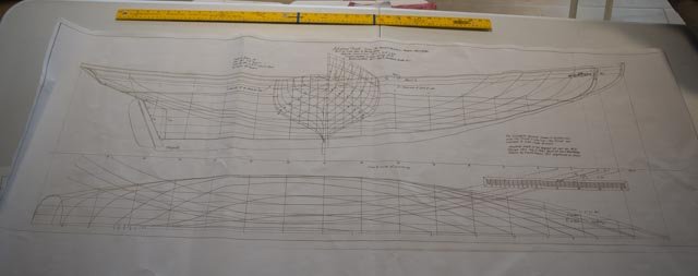 Here are the hull plans they shipped. They are basically at 1:32 scale just off a hair.
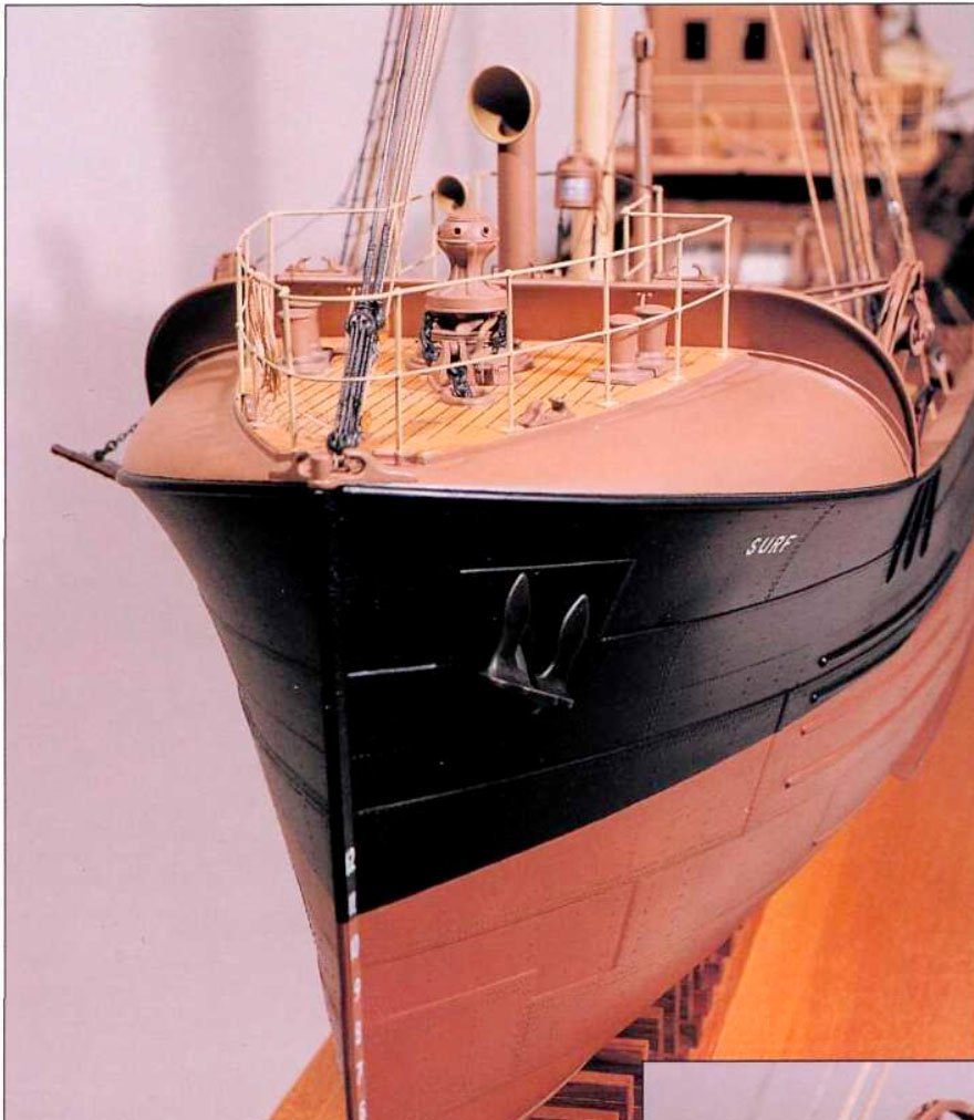
Before we get to the hull let’s gather all the other info we plan to use. There are no surviving drawings of the on-deck configuration nor sail plans, but artistic license should warrant a “close enough: / generic finishing above deck. So let’s find some photos. Here is before bowsprit and racing with a bowsprit.-
2.
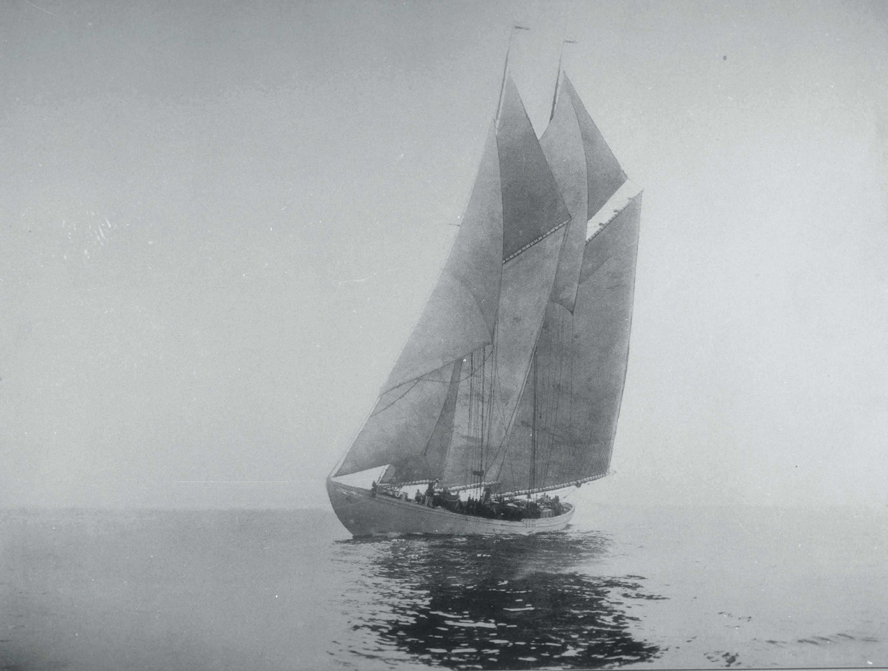
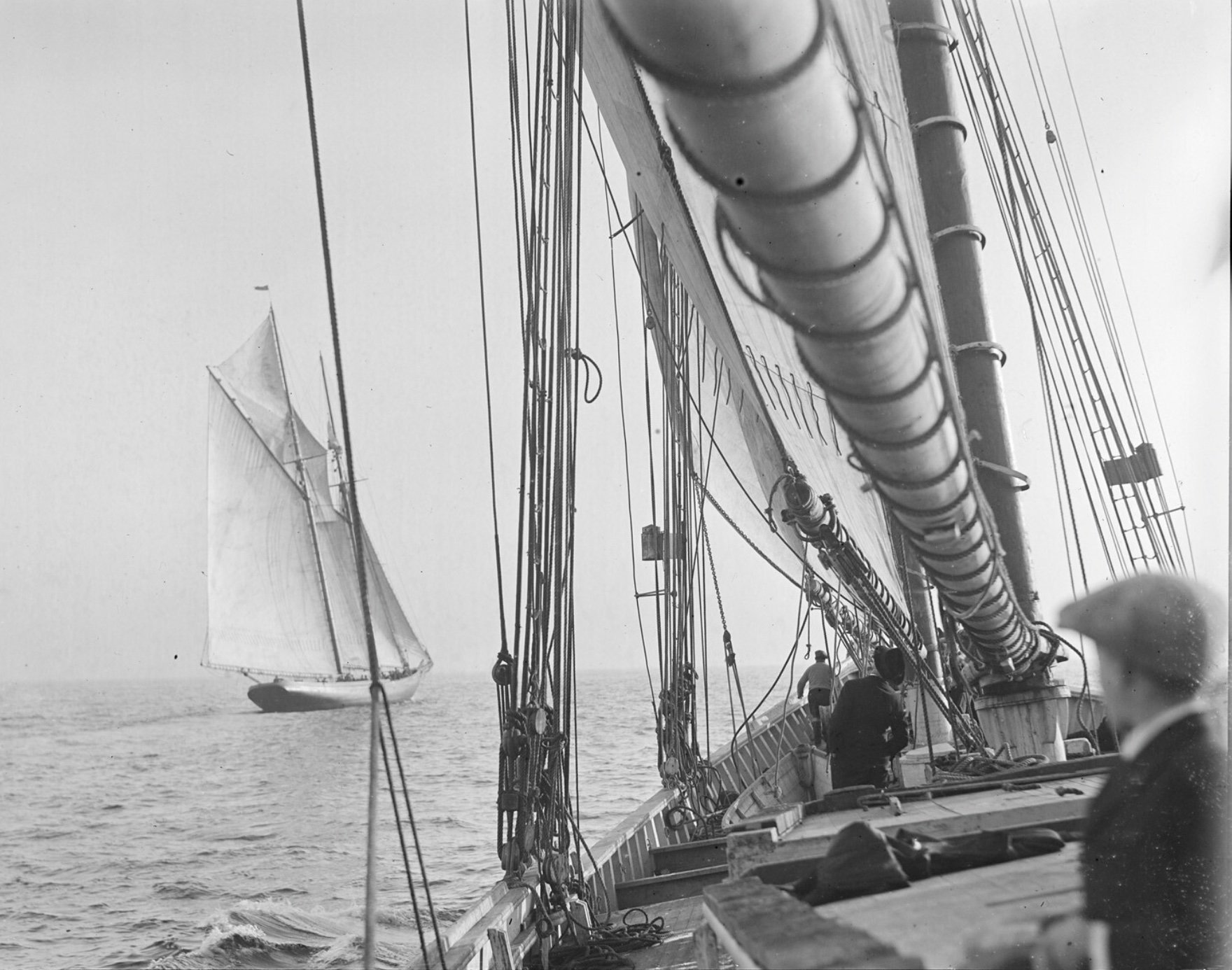
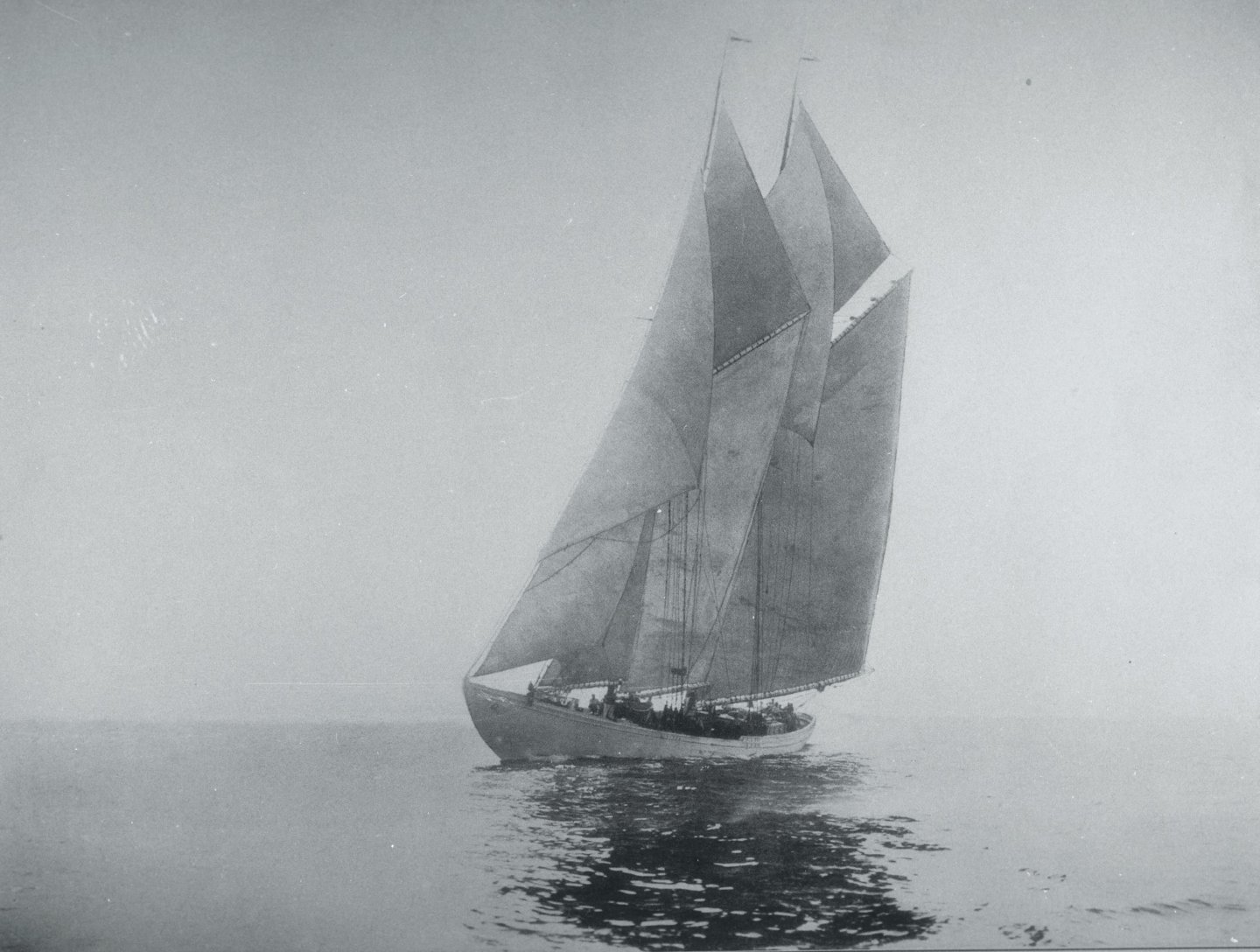 this view is one of two images I am after….note there is no bowsprit in the image. This shows the working vessel.
-
3

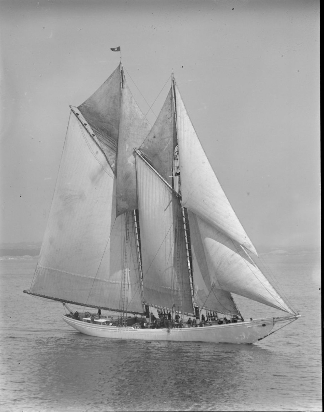
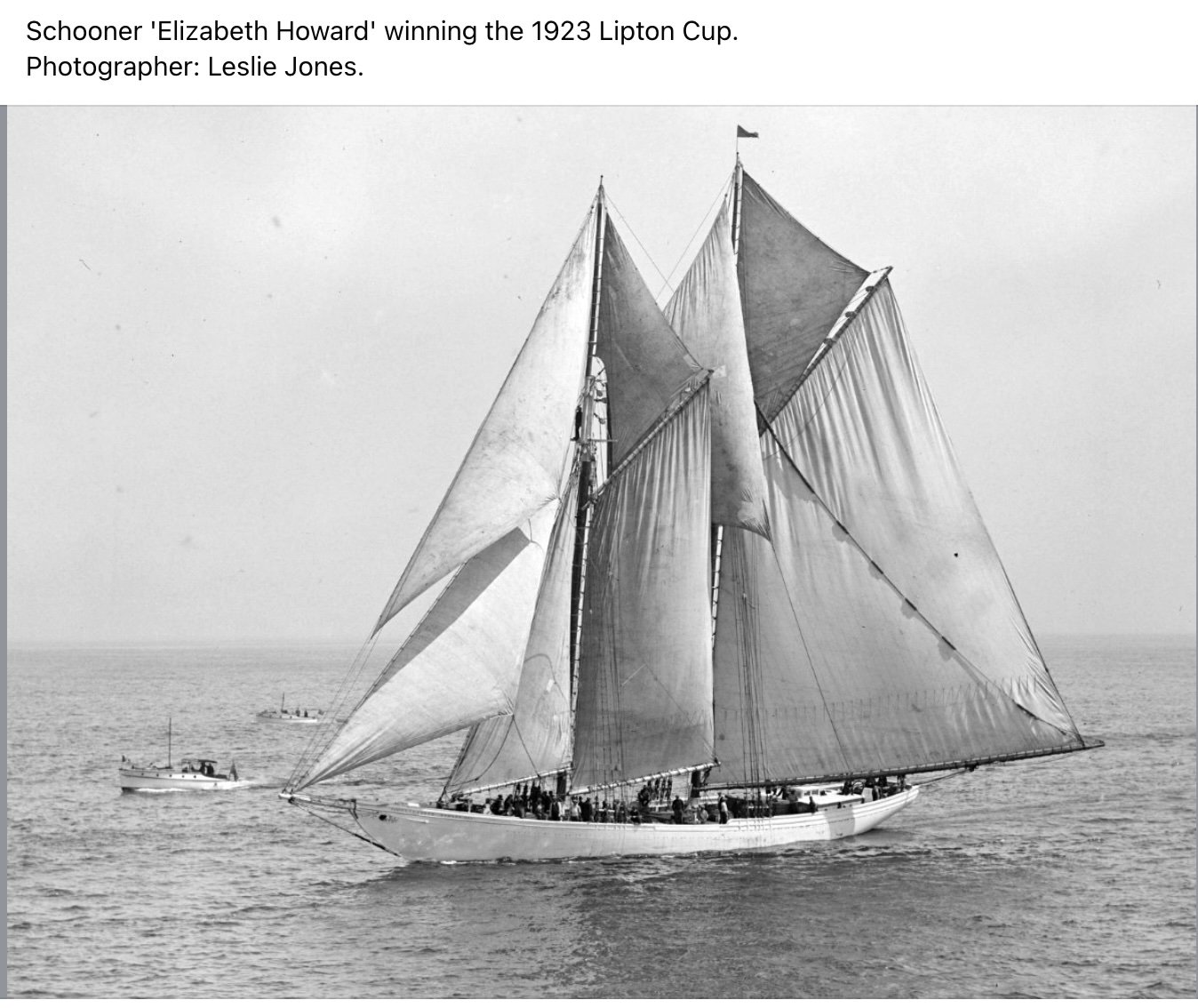
- here we are racing in all her glory….the likely choice.
The other option having no deck plans could have been to use the great hull drawings and do all the in between framing and show it in the yard under construction. I chose not to follow that approach for the "White Ghost" of Maine. I think it is the sailing image of such a short lived thoroughbred racer to be the better way to go, so off we go.
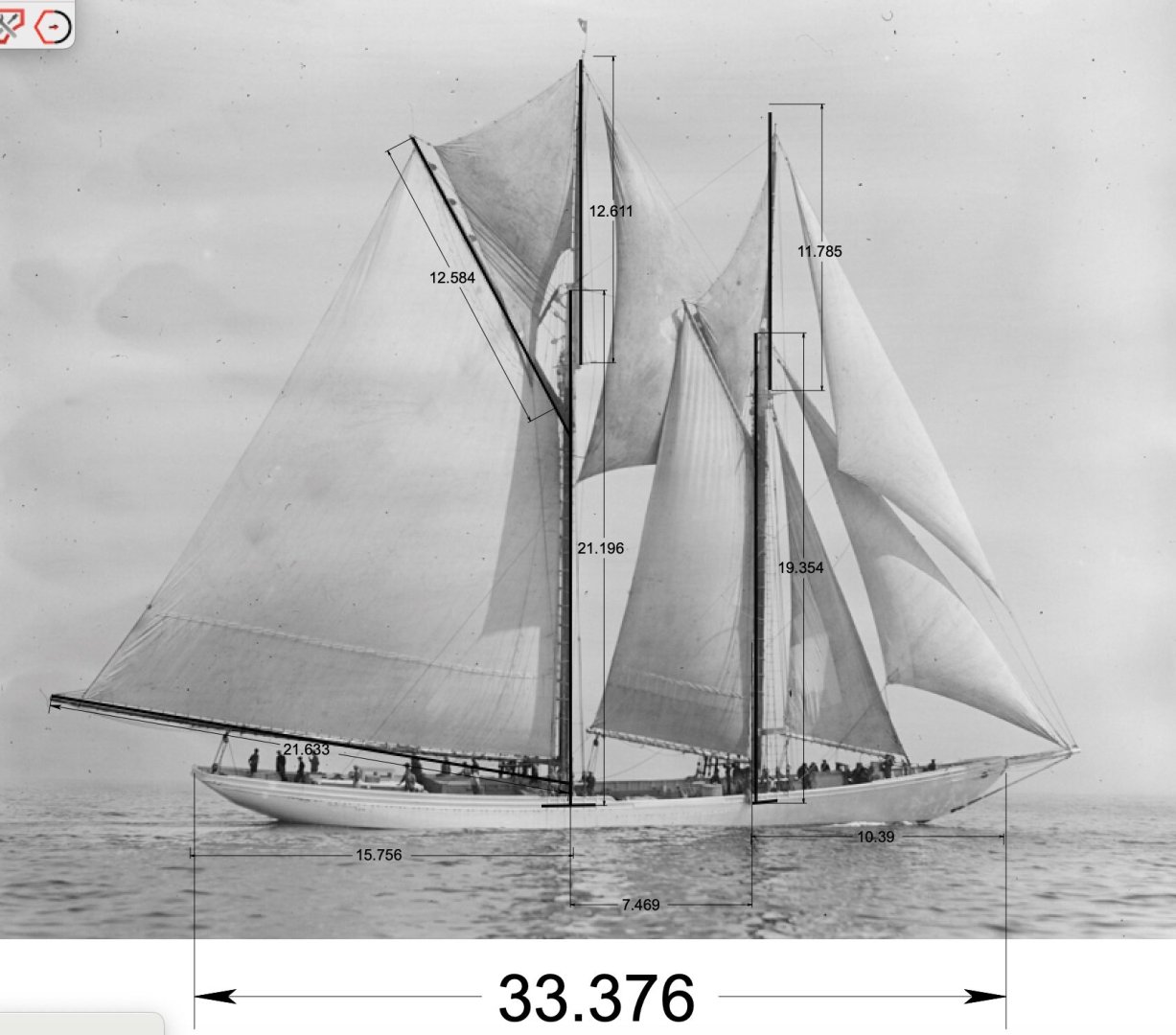
To complete my outreach at this point for the above deck, I will use two photo documents and will annotate them. Once again, I have taken a broadside photo and embedded it in cad and scaled it. I found it strange with the subtle roll to starboard of the hull in this image, the masts are absolutely plum. I will add a bit of a rake as can be seen above.
-
4
 . here is screen shot.
-
5

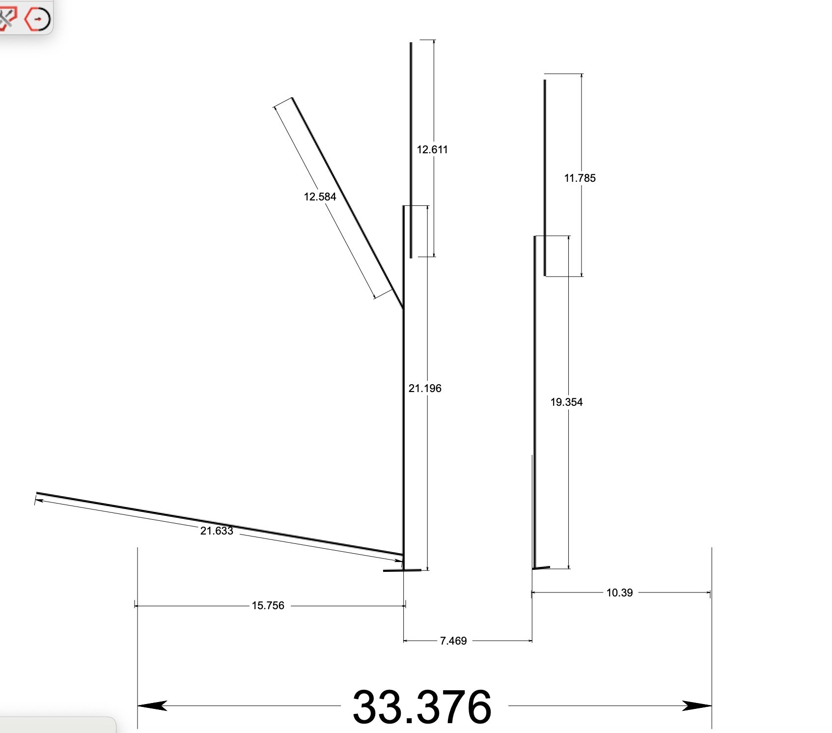
- by example of the next steps, here is the spar plan.
-
6
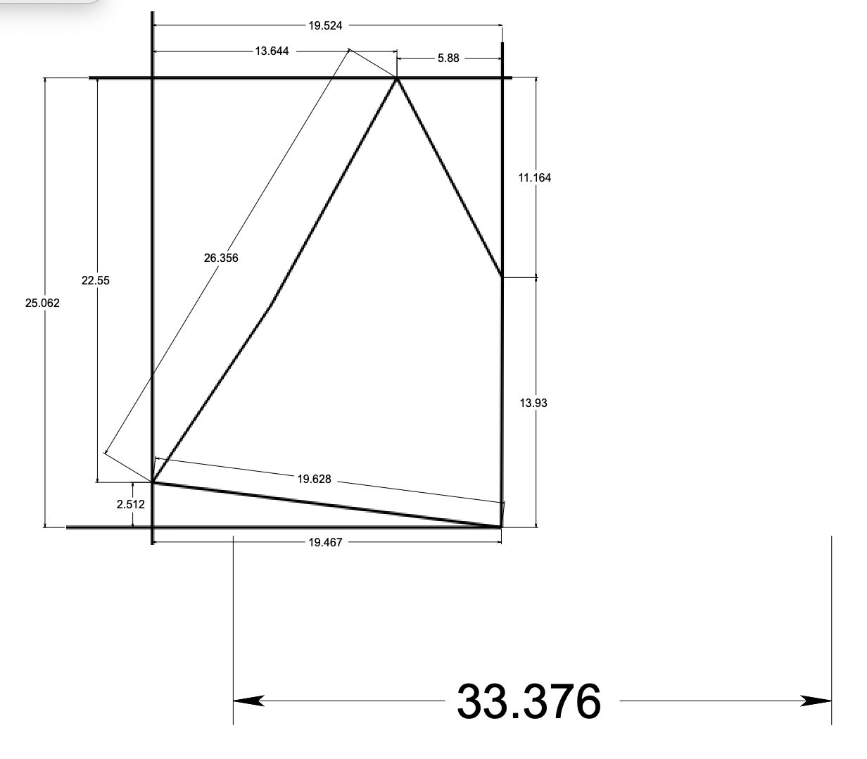
- here is the first sail plan. I will later do one for each sail. Where like this mainsail where they are larger than tabloid 11”x17” my printer limits, I have added coordinates to lay out the pattern manually. Smaller sails will simply be printed.
To place furniture on deck I will use the 1919 photo of her in the water swamped to give running on deck dimensions for the cabins that are visible. There are also a few online images for Bulwarks etc.
-
7
 Here is the partially annotated photo of on deck.
-
8
 here is sample of online deck views . Yes that is Columbia with I assume Captain Ben Pine ahead of us.
I will then use Gertrude Theobald and Columbia plans that I have rolled up somewhere [ the once upon a time to build list] for added guidance. More on that when we get there.Cheers
- GrandpaPhil, etubino, ccoyle and 2 others
-
 5
5
-
1.
-
Allan
ah you are right again....good eye to the other old guys...thanks Druxey.
-
1 part b the oops revisited.
Thank you all for your interest. the short answer is Allan once again is right on. I add this reply to the first post.
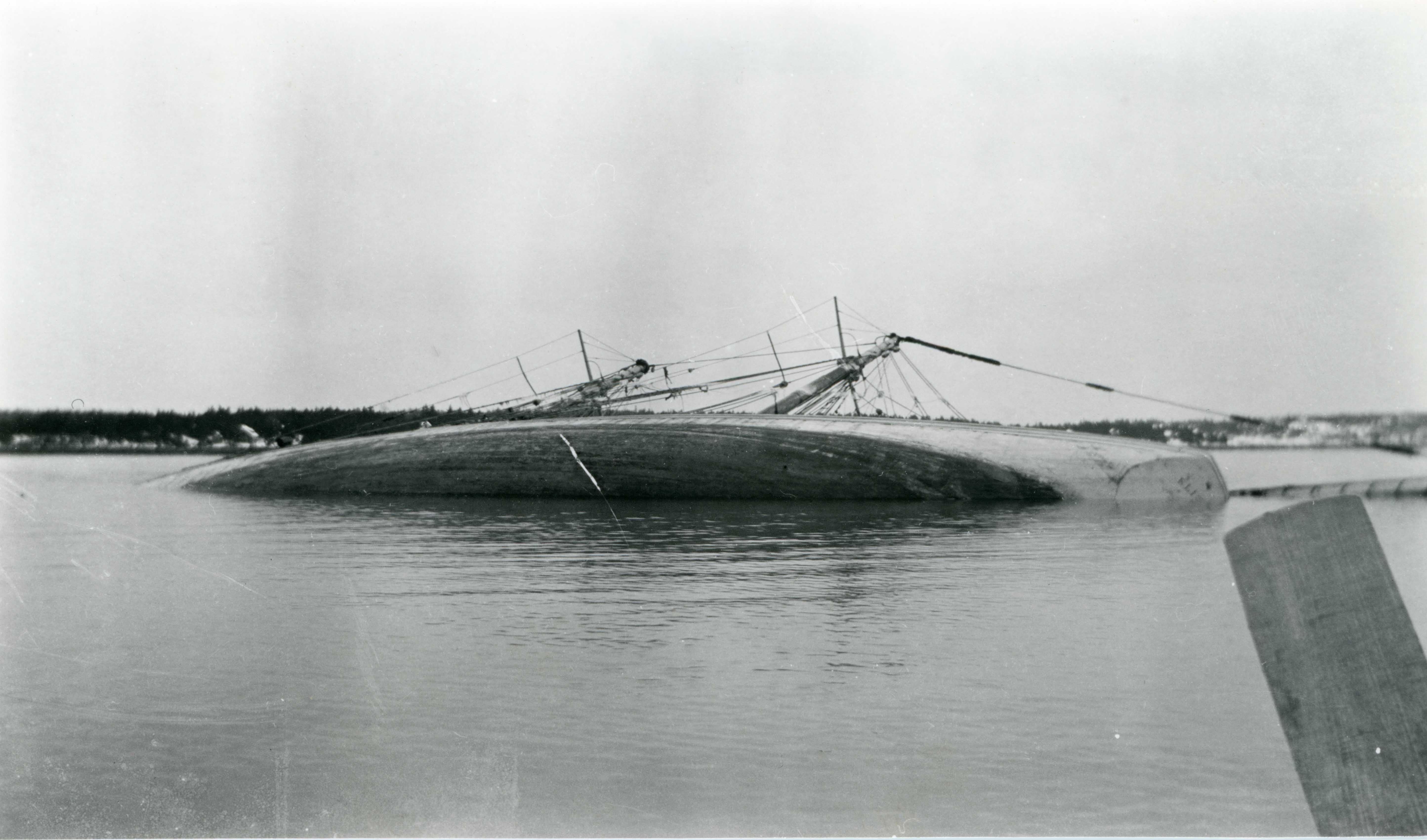
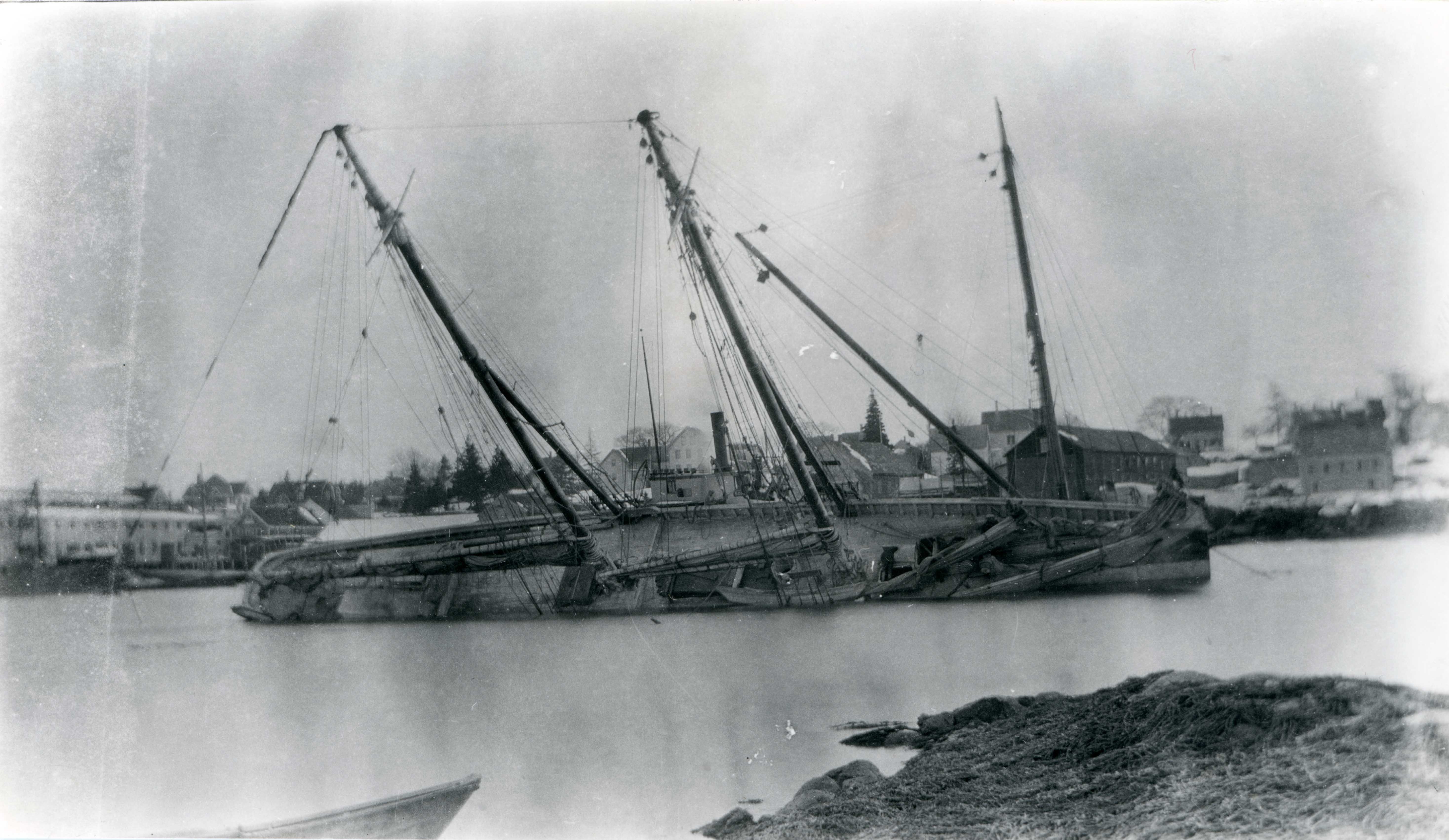
I am happy that I will be able to answer the query as to what is in the photo of the January 1919 accident. Fortunately, there are a few more views that I share here. As the story goes, three years after her launch she was sailing by on her way to Boston and decided to come into the yard of her birth for a pit stop. The crew at the time were most likely not local Mainers, Boothbay at any rate. When they anchored, they were over a ledge, and unfortunately, they all went ashore for a break. Town is about two miles or so away and out of view. As the tide went out, over she went. See these two added photos.
-
4.
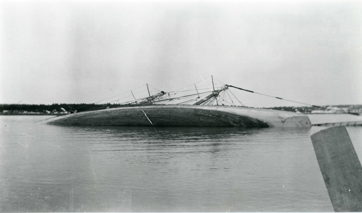 looking East across the Damariscotta River
-
5
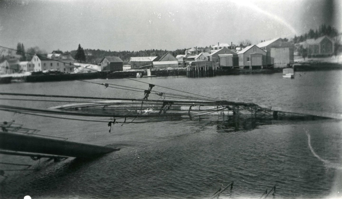 Looking west toward east Boothbay. That is the Hodgdon Brothers yard in the view.
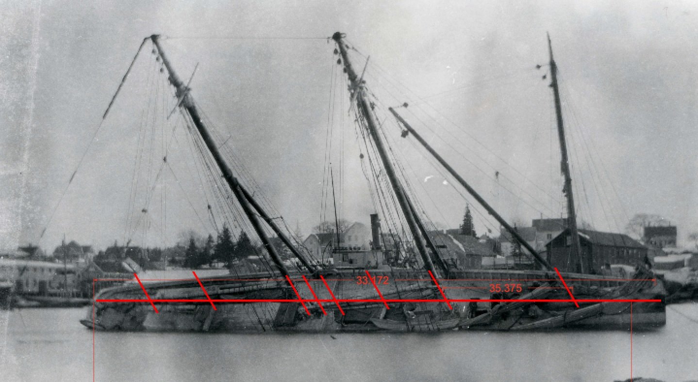
I took the image I shared before and annotated if for the record. In this view of interest, one can also see all three of the 1919 active yards of East Boothbay. One can then see the derrick barge beyond the hull. Presumably this photo is after they had pumped and rolled her back a bit. If one looks clearly ,as Allan did, the lighter colored bow is there.
6
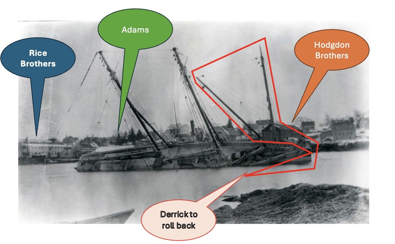 here we see the annotations. In these early days she sailed as designed with no bow sprit. That appendage came later when racing.
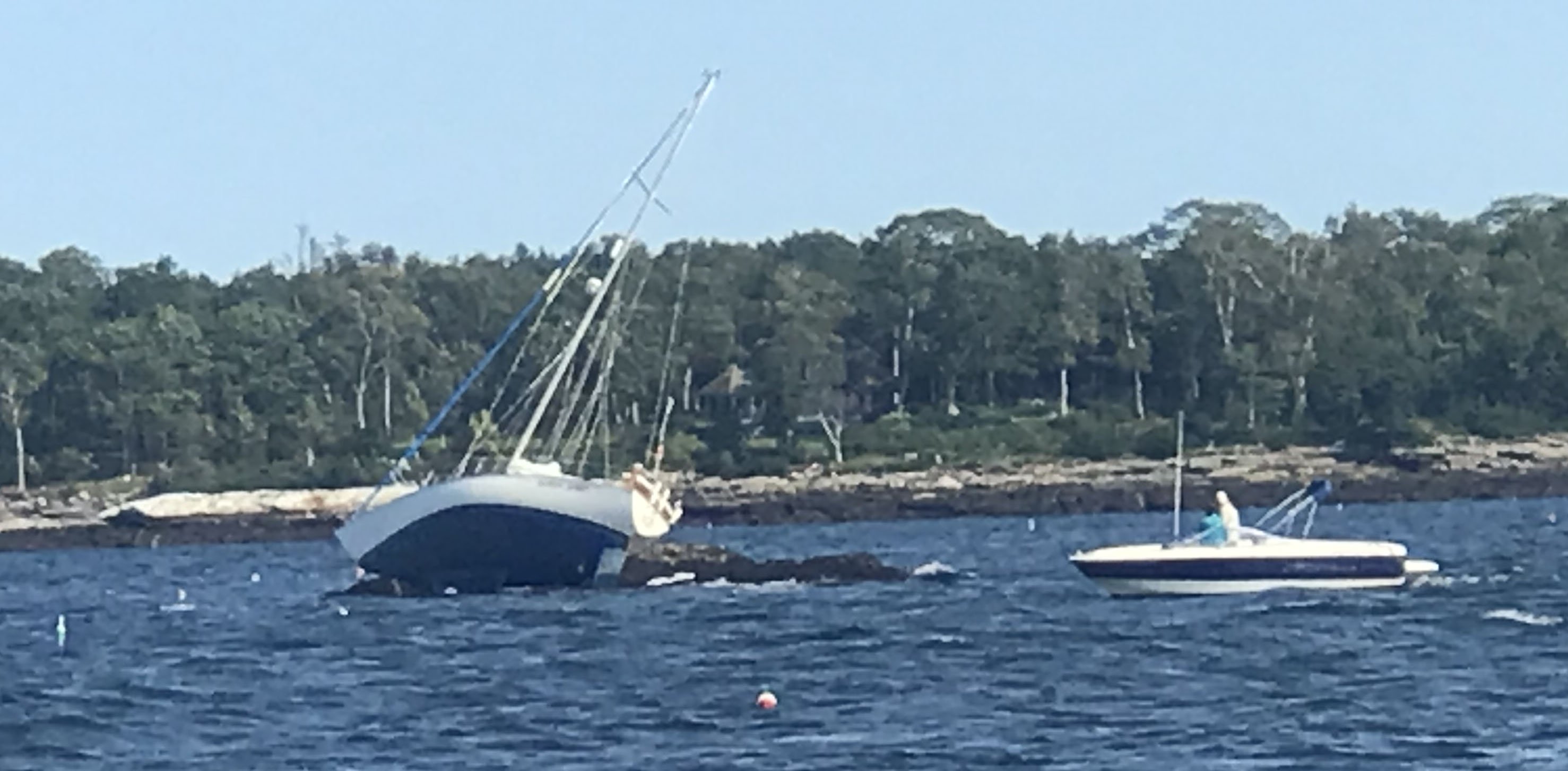
Just for fun I share a more recent photo of other sailors “ from away” coming into Boothbay and anchoring over a ledge….oops.
-
7.
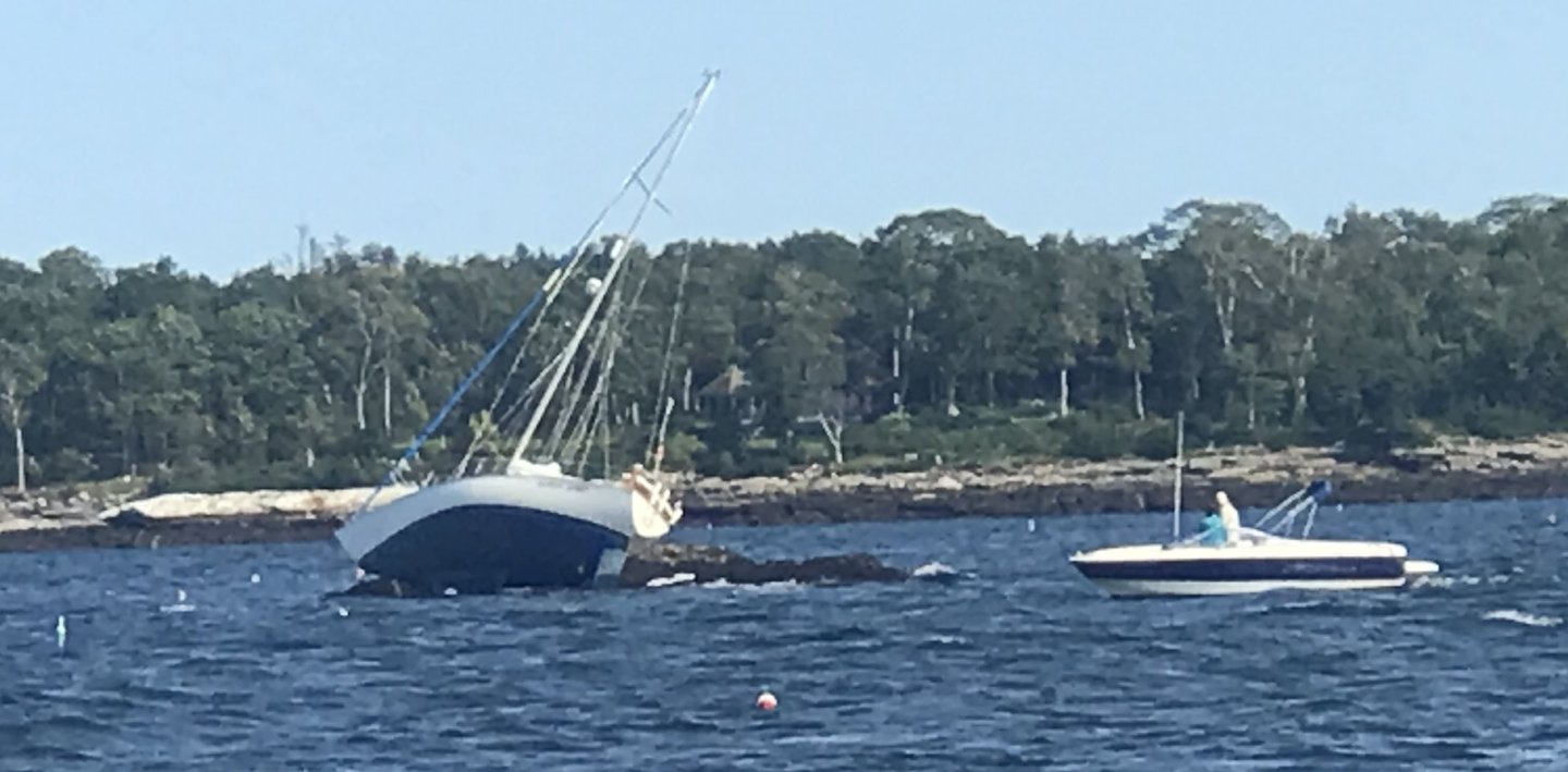 sailors “ from Away” fortunately, this event ended well as reportedly the crew had a nice evening in town and then about midnight, at high tide, Sea Tow got them away.
Cheers
- yvesvidal and Roger Pellett
-
2
-
4.
-
Rick. always a pleasure to hear from other Mainers. Your work on Flying fish is incredible so I am honored.
-
1 The beginningThis part of a build tends to take the longest time. I have been mulling over modeling this schooner for at least 5 years. Where to begin? My introduction to her was seeing two pictures at our local Boothbay Region Historical Society. One view was of her launch and a second of an accident later in the same home harbor.
-
1
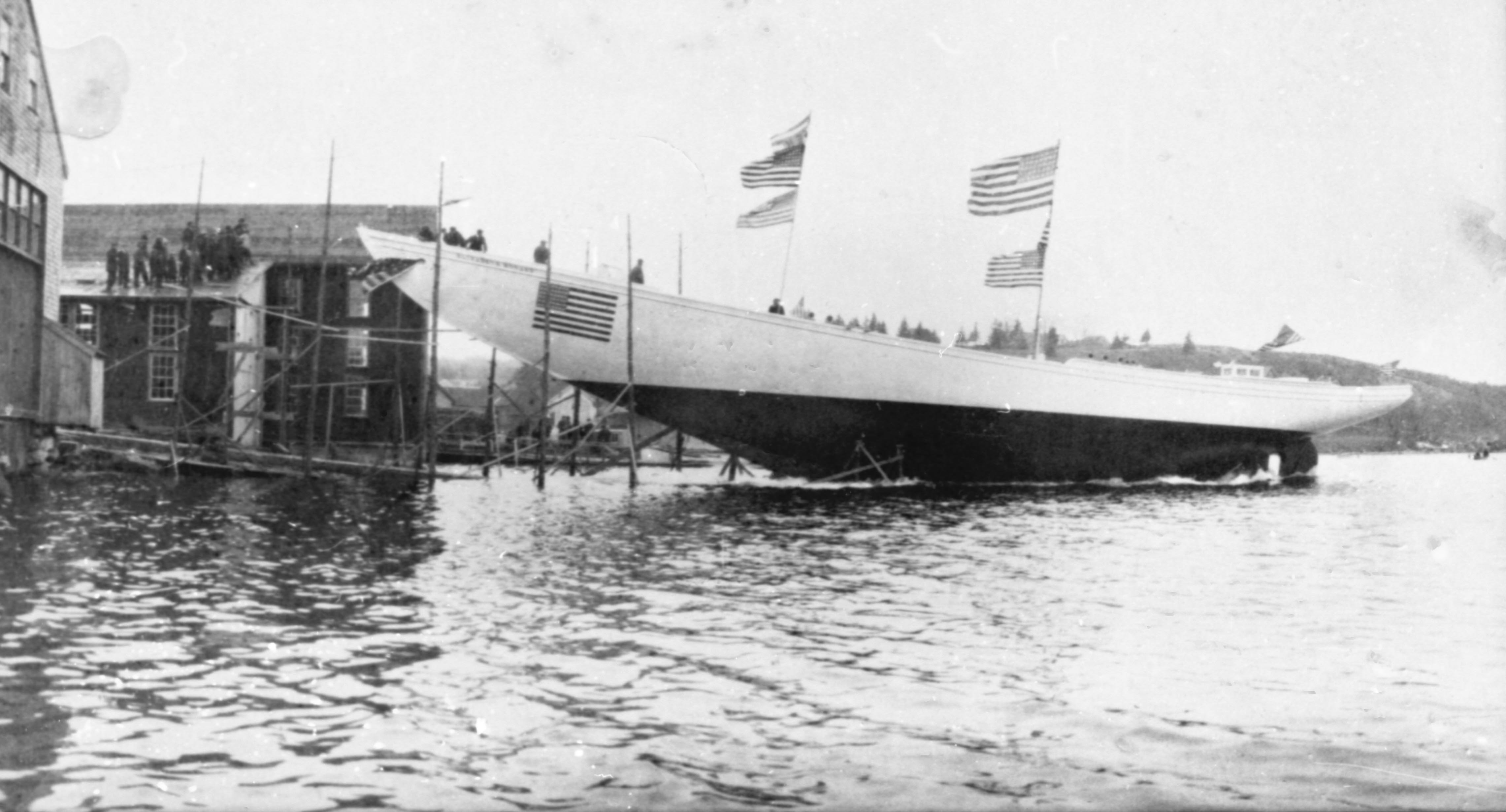
 launch day
-
2
 oops inexperienced crew perhaps better said " from away" anchored over a ledge, and we have 10-foot tide.
The story and other images are in our local newspaper as a history article. It was January 1919, and she was full of fish. They pumped her out, took her to town, unloaded the fish, and raised her on the railway. All was well so then back to work. She was more of a hauler of mackerel than a fisherman in those days.
Having recently completed my big Bluenose I moved onto other builds. Then a few years later I learned about her racing history….wow and from Maine too!
-
3.
 great view as she completed the Lipton Cup race in 1923 with Ben Pine at the wheel. this image came from Facebook site for the Fisherman Festival in Gloucester
I then fell into an article from NRJ vol 46 starting on page 12. A member, Daniel Turner, did yeoman’s work to uncover the story of her mysterious length. Unfortunately, there are no surviving records from the Adams Shipyard here in Boothbay. Paul Adams, a grandson to the last builder is past 95. Sharp as a tack, he came to my talk a few years back on the history of the Boothbay Shipyards and sat in the front row. He corrected a spelling in one of my slides but alas when talking after he had nothing to do with the yards. As a matter of record, they had closed by 1921.
Back to the story of why this build. I am trying to build things for each of our yards. The Adams family shipbuilding started about 1810 and ended 110 years later. Pinky schooners first and then many schooners, a few brigs, a ship, and other vessels ending with some tugboats and a motor yacht in 1920. Their last sailing vessel was the 3-masted schooner, Priscilla Alden. launched in 1918. I started to build a model of that schooner a few years back, but the records here showed a discrepancy in length of the Priscilla Alden, that I documented there and had to make a choice of who to follow. I chose to defer and build another schooner, the Ada Cliff built across town.
Having recently built two steel hulled vessels I felt it time to go back in time a bit and take on another Schooner. I have about 5 of them on my to-build list and the White Ghost looks like a fun place to start. I highly recommend any schooner lovers out there, especially any Mainers or Bluenose people to chase down the NRJ article The Schooner Elizabeth Howard and enjoyed it. Ten years ago, I built a big Bluenose [ 1:24 scale]. I went to Lunenburg twice over that build and fell in love with the saga of the Fisherman’s Cup Races.
In several books they talk about the challenger, but some focus was given to the field of contenders. More so when like the Starling Burgess designed Schooner Mayflower owners tried to enter. What they had built was truly a racing machine that only looked like a fisherman. She was kept out of the races due primarily to the small volume below decks set up to race and not to collect fish. It is interesting to note that one of the schooner Elizabeth Howard’s options was to be sold to the schooner Mayflower owners to use as a match boat if Mayflower ever would be qualified for the Fisherman Cup.
There is a bit of fate to this story too. The Schooner Elizabeth Howard was bult in 1916 and was quickly followed by her 126-foot sister the Louise Howard in 1917. To satisfy her owner, Thomas McManus took is 1908 design for the schooner Oriole and extended her bow. As said above…she had to be fast! In her early years she was known for speedy long runs full of fish that she typically bought in Nova Scotia to race south. She was reported to do 16 knots in a good blow. When the Fisherman Cup races became popular in 1920, her owner wanted to get involved.
The problem she had at first was that she was not associated with the Gloucester in-crowd. With a New York owner, and having been built in Maine, she was not accepted to enter the races. After the 1921 loss to Bluenose the Americans were scrambling for the next year rematch. The top two schooners to contend amongst four were Henry Ford and Puritan. The Puritan, designed by Starling Burgess, was launched in March 1922. As part of her prequalification, she was off to the grand banks to fish. Disaster struck and she was lost in her first summer. Ben Pine [ future Columbia and Gertrude Theobald skipper] was preparing to race her so now he was looking for help. After Elizabeth made a reported amazing fast sailing return trip to Boston from the banks and the schooner Puritan was lost, Ben Pine, made arrangement to get Elizabeth qualified. He then took her on and in 1922. In the best 2 of 3 series, she raced but broke a topmast on the first day and was beaten by the schooner Henry Ford in light air on the second day. The Schooner Henry Ford competed for the Fisherman’s Cup but lost to Bluenose.
Elizabeth won the Lipton Cup races in 1923 but after that win, Ben Pine moved on to the new Starling Burgess designed Columbia. There is a large collection of photo images of these races on the Boston Library website. Elizabeth’s distinct white hull surely makes an impression, and it is easy to see how she got her name…the White Ghost. The unfortunate end of her story connects her fate to the schooner Puritan. It was later in the fall of 1923 when just like Puritan, she was lost off the coast of Nova Scotia.
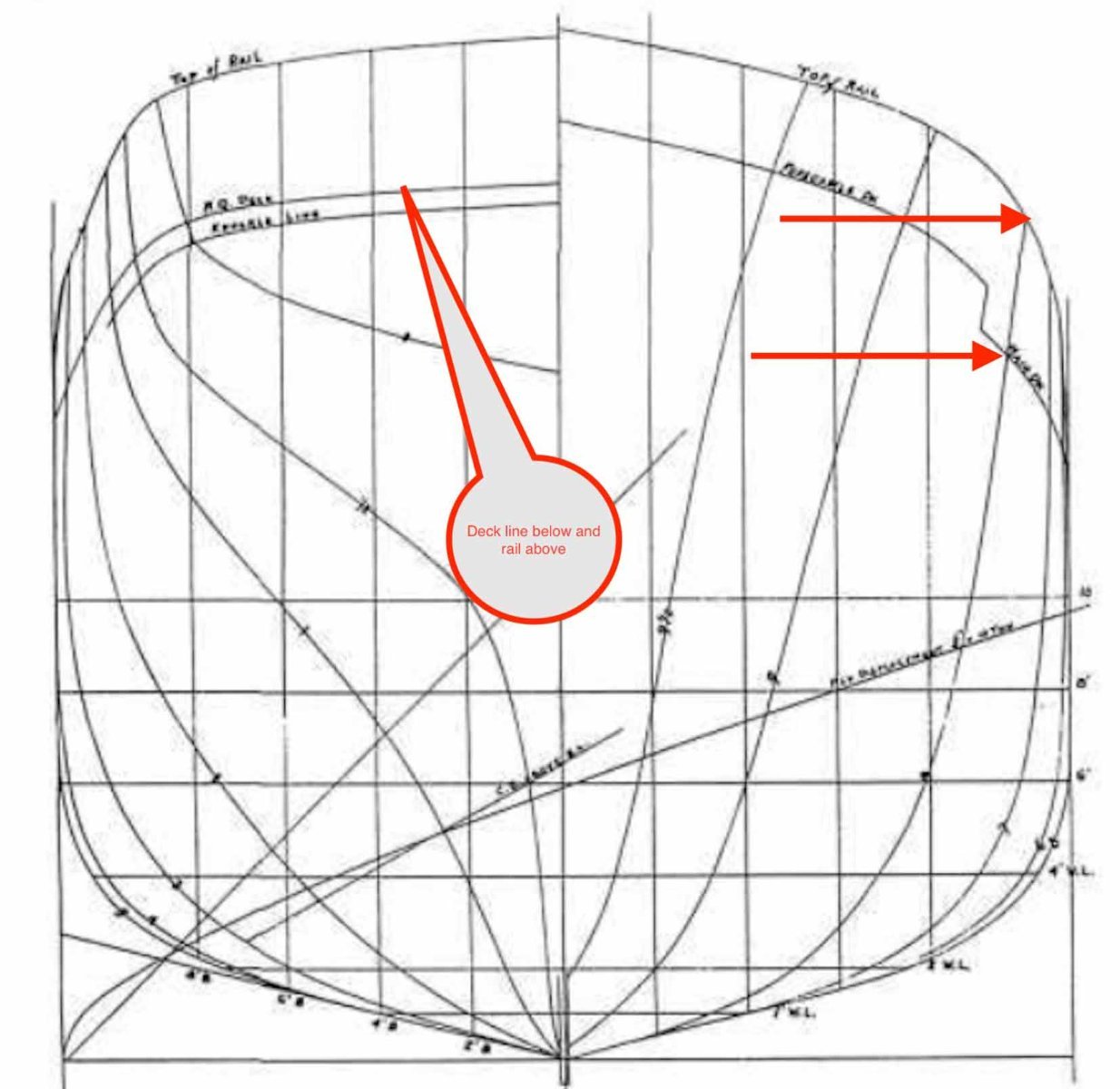
What was her length?
Let’s look at her lines for a moment. Daniel’s NRJ article touches on the racing and then proposes a solution to the length mystery saga of the Elizabeth Howard. She was designed by the renown Thomas F. McManus. Howard Chapelle includes the lines of Elizabeth Howard shown annotated over the lines of an earlier 1908 schooner Oriole. The schooner Oriole was 127 feet at the rail. The only change was to push the bow forward [ in scale] 6.5 feet. The only reason to do this would be for speed. she started as a knockabout [ no bowsprit]. The confusion comes from a note on the Chapelle document stating the length at the rail being 148.
The short version of Daniels work is a follows.
• A Fisherman Cup racing vessel must be less than 150 feet.
• The reported bowsprit added to Elizabeth was 14 feet long.
• If one scaled the Chapelle drawing showing the extension one gets 133’6”
• Add the bowsprit and you are under 150 at the recorded 148 feet.Go with the 133’6”. I think that is more than good enough and it is what I will try to build.
All for now
- GrandpaPhil, Jim Lad, ccoyle and 6 others
-
9
-
1
-
9 The end
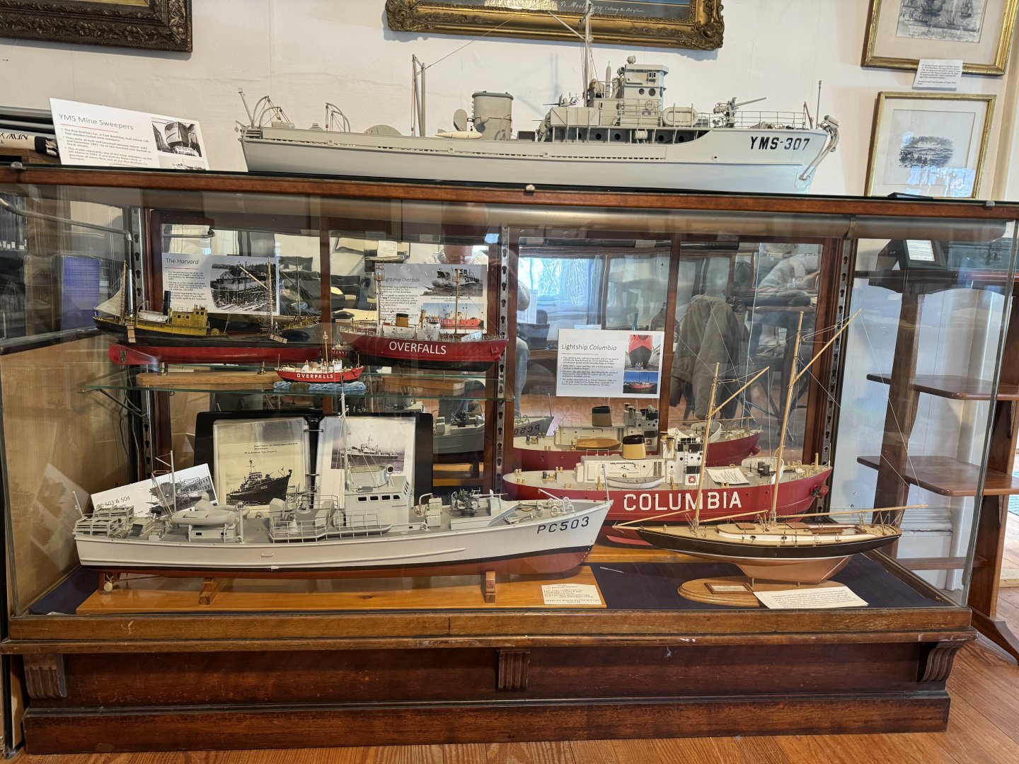
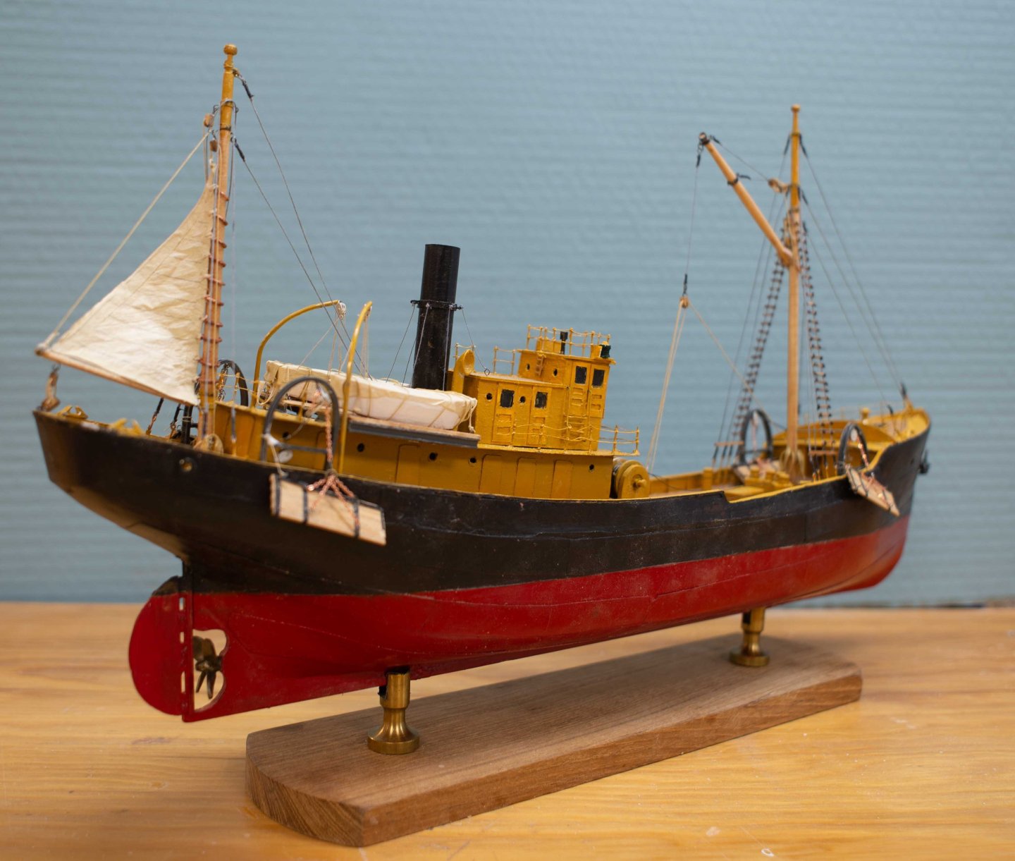
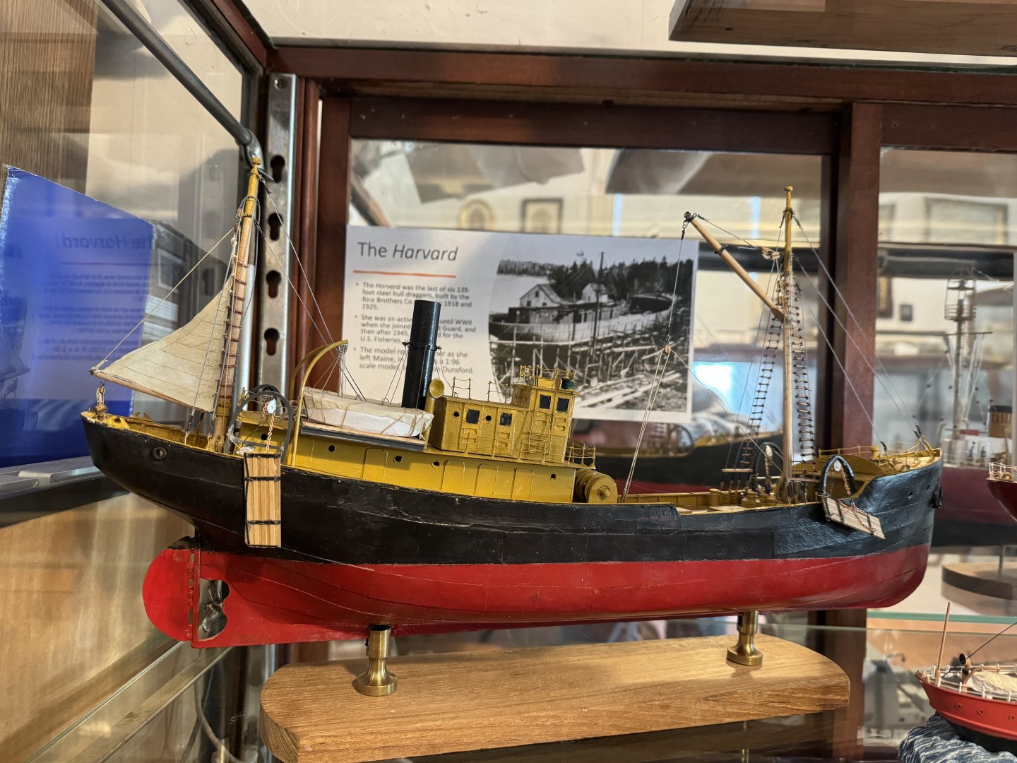
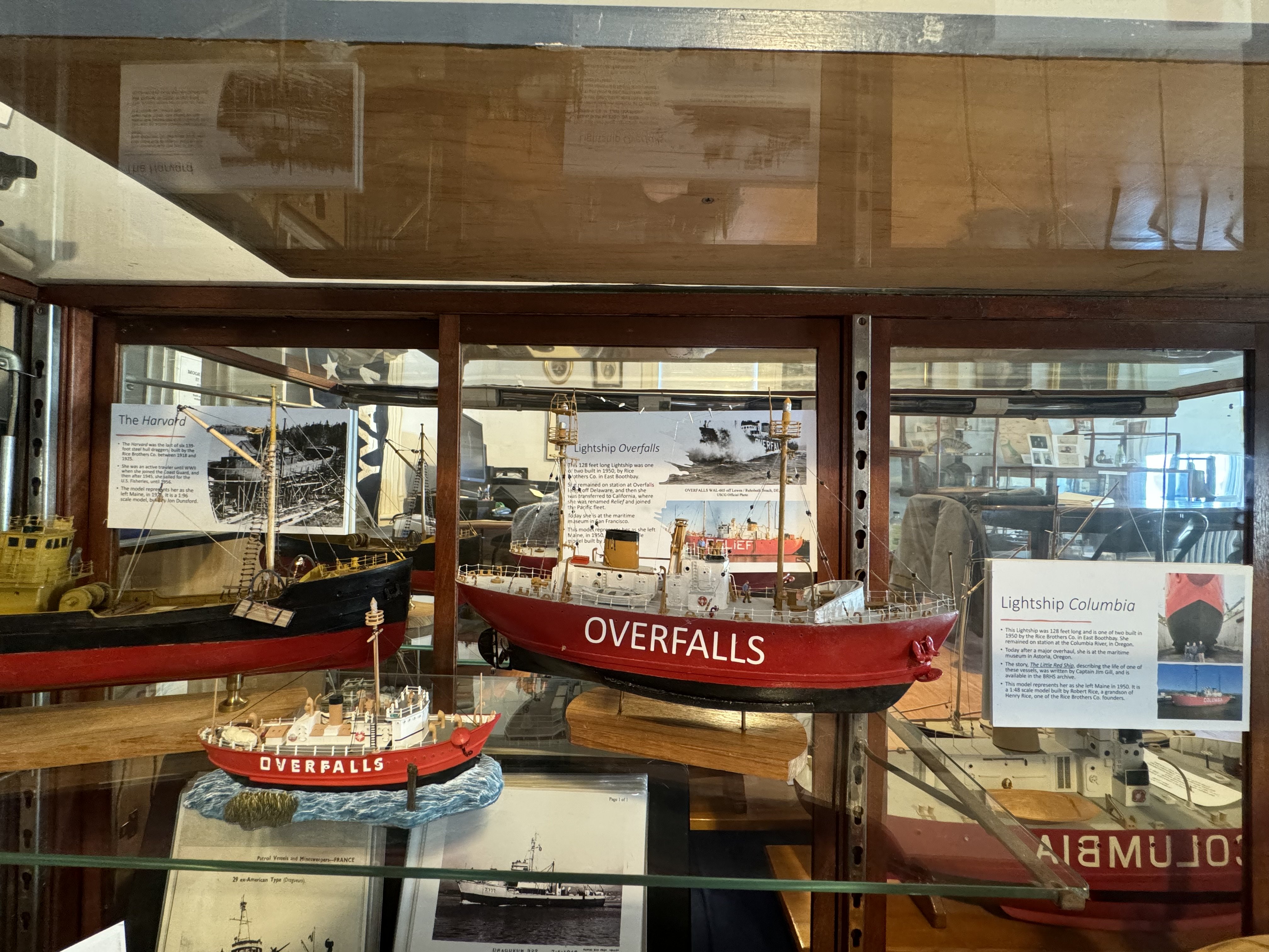
It has been several months since setting this model aside to wait for its partner. Both this model and the Dragger Harvard of the Rice Brothers shipyard are now on display at the Boothbay Region Historical Society for the summer. I will give a talk in July on the History of this yard and its people and that event will end this effort.
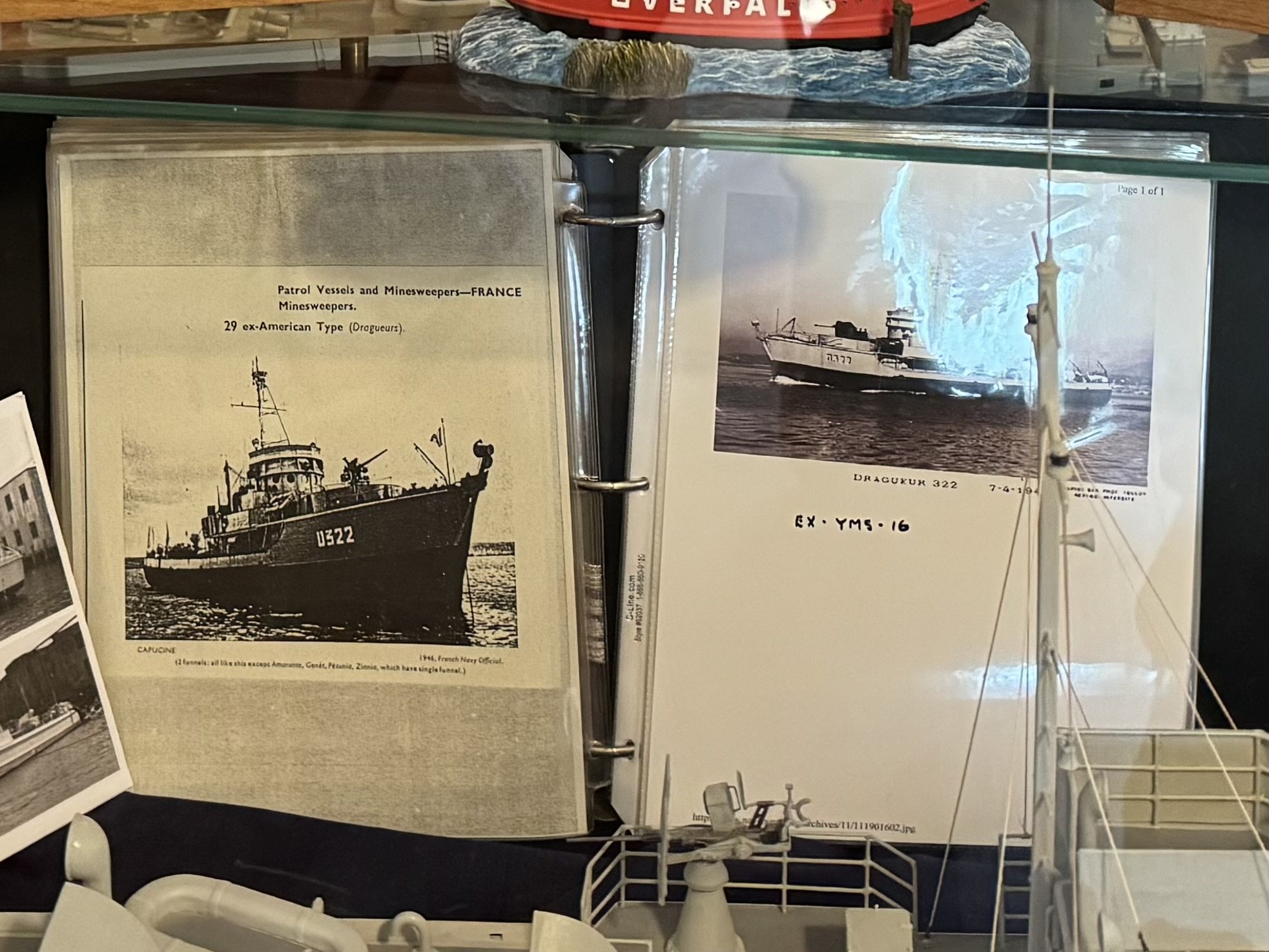
Here are a few images of the display. They include my two models and three made by Robert Rice , grandson of the founding Rice Brother Henry. Robert recently donated his collection to the society including these three models and 20 volumes [ one sample in photo] of photos, news clippings and other data tracking the 70 years of their work. the yard not only built 4 US :ightships, but 11 subchasers and 11 minesweepers during WWII. the yard today ois the very successful Washburn and Doughty yard building many sea tugs.


I am now off to another build and look forward to more sawdust
- GrandpaPhil, ccoyle and Canute
-
2
-
 1
1
-
12 The end......
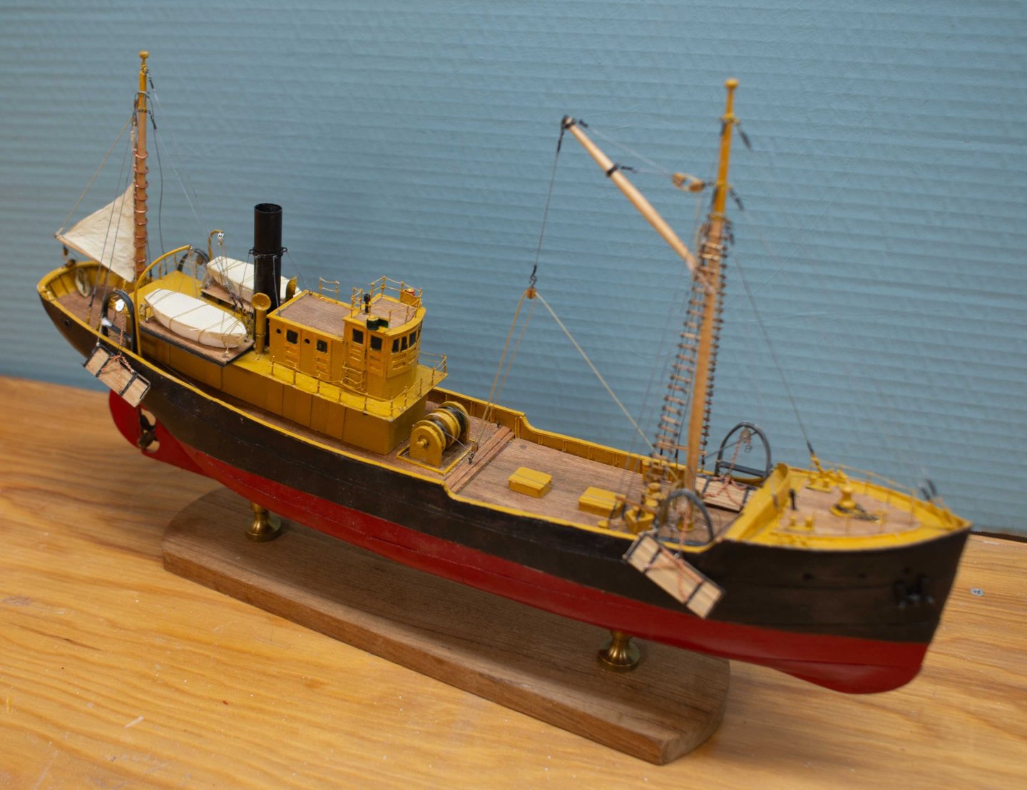
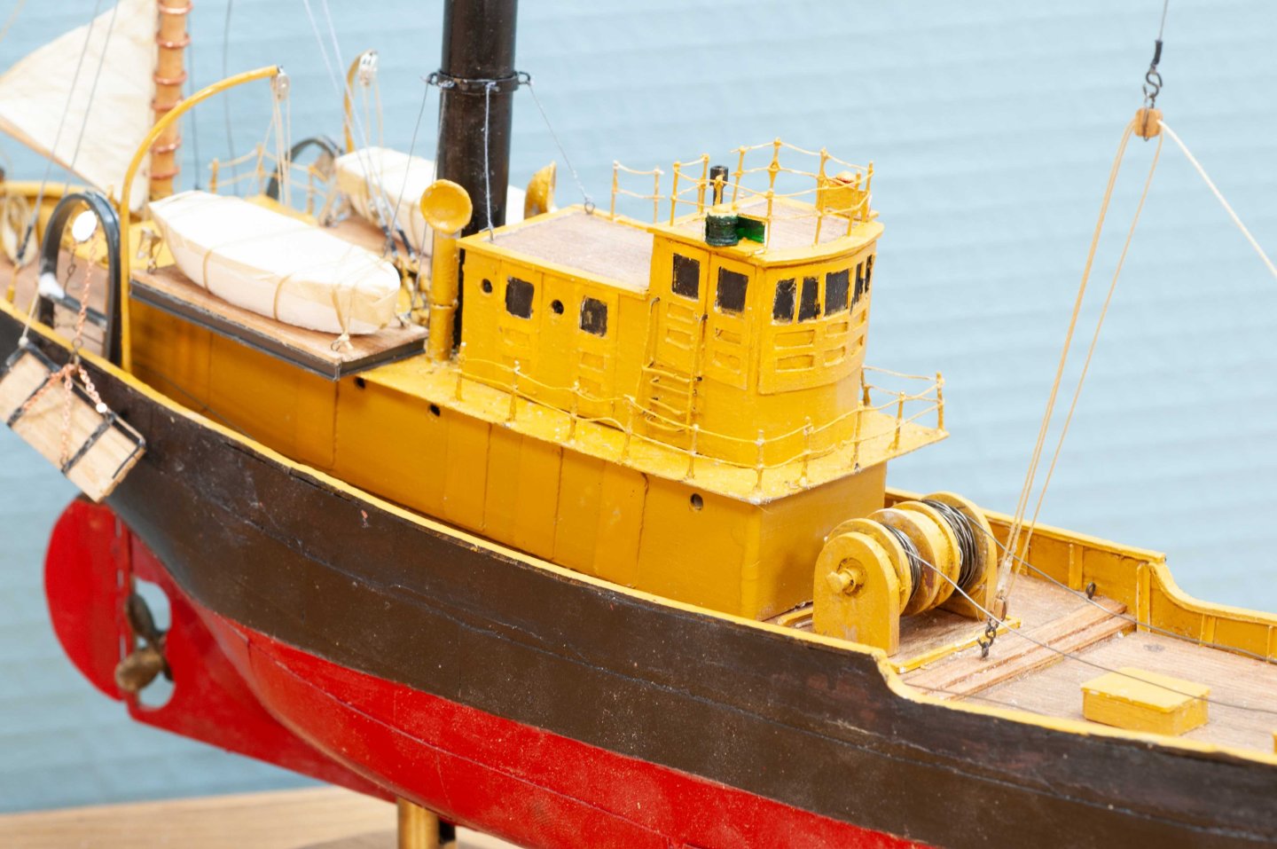
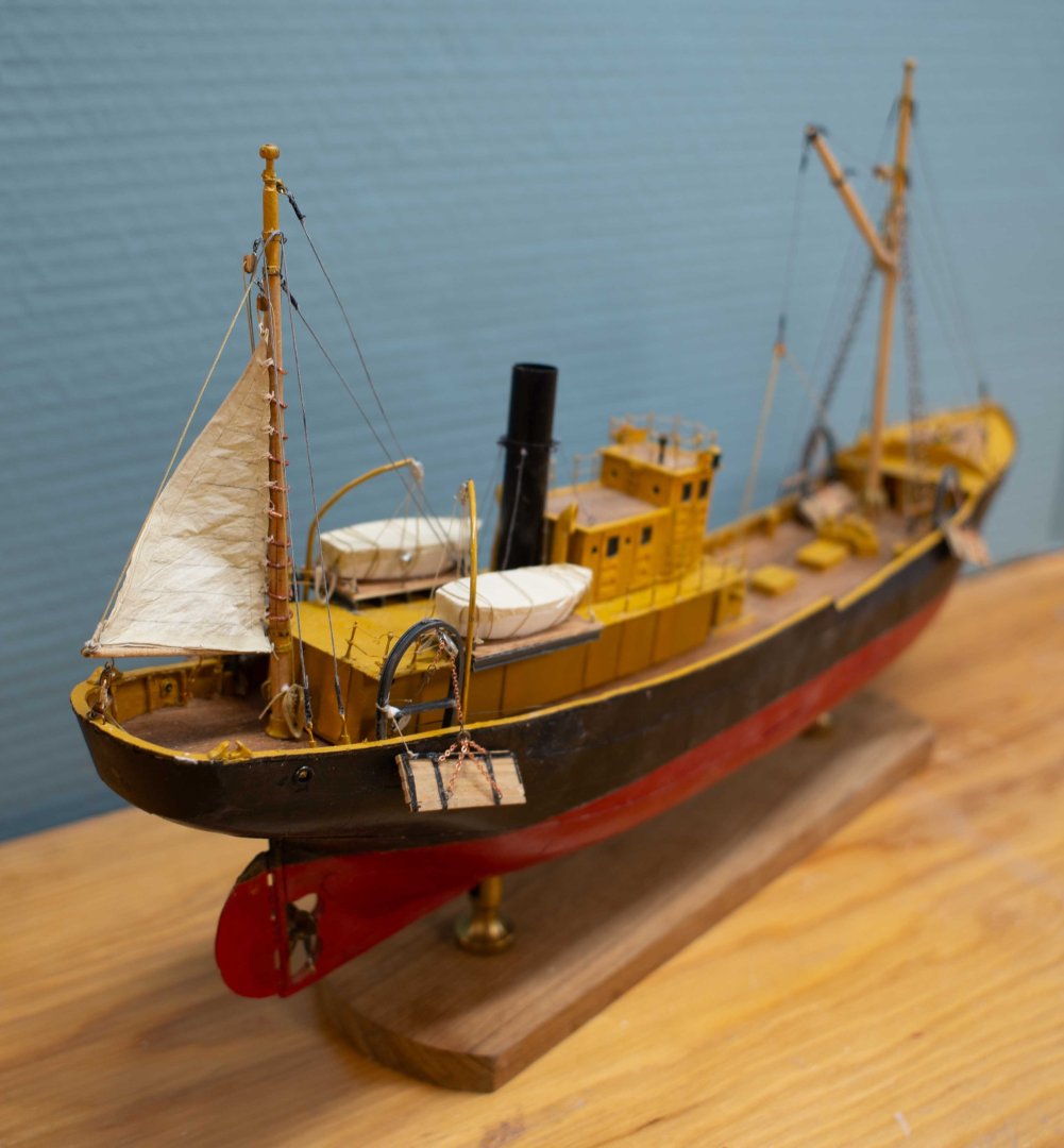
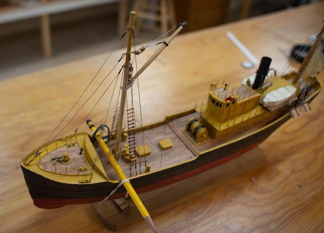
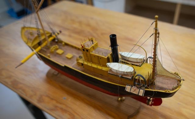
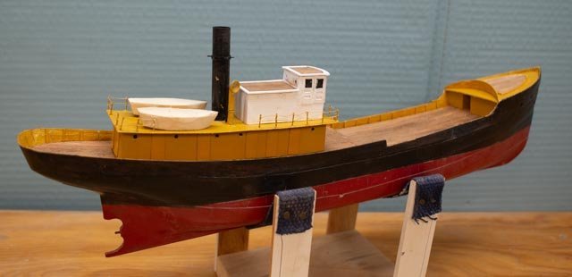
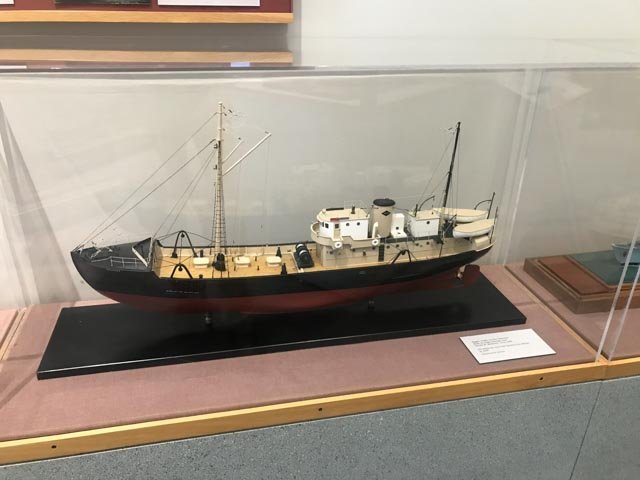
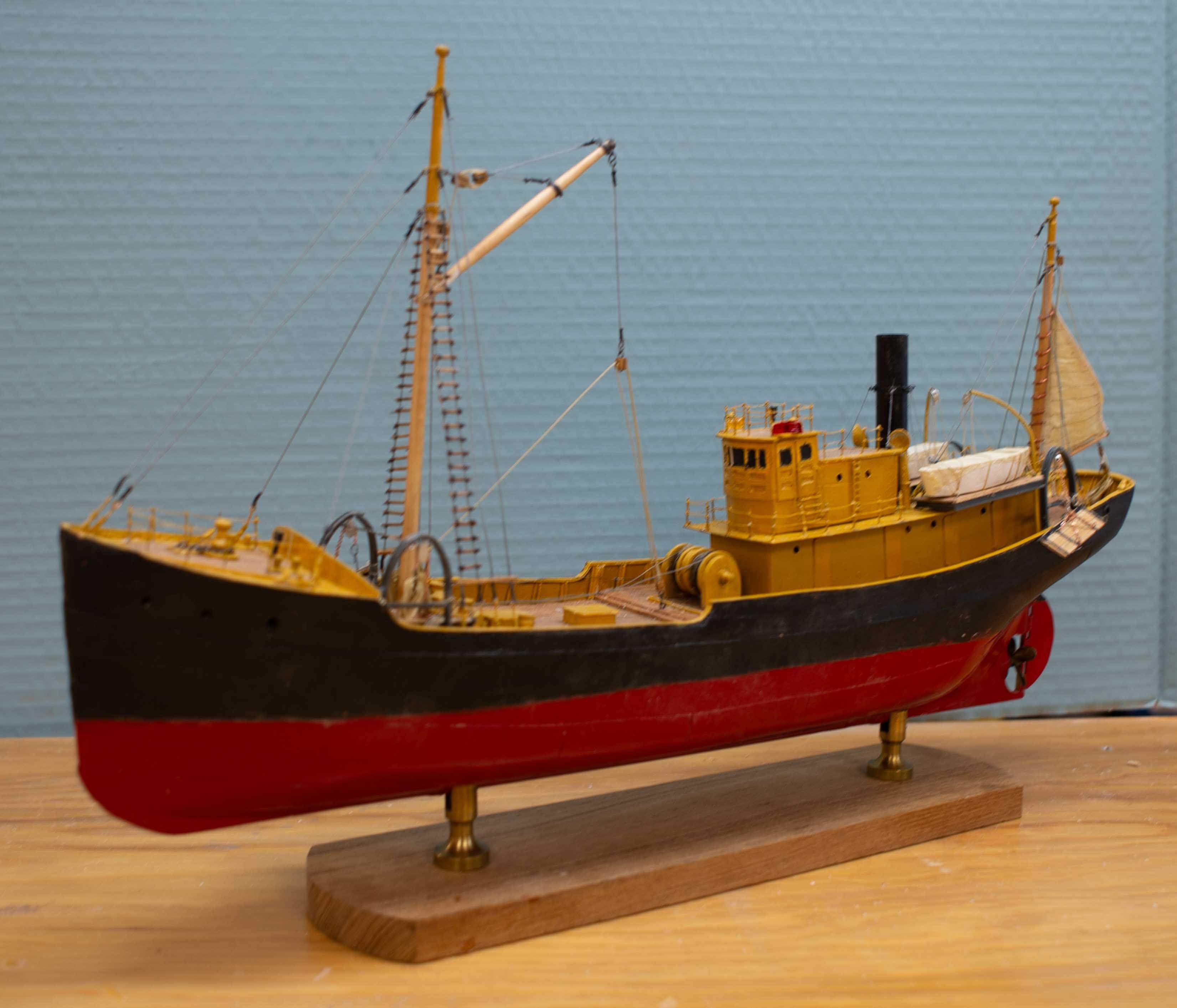
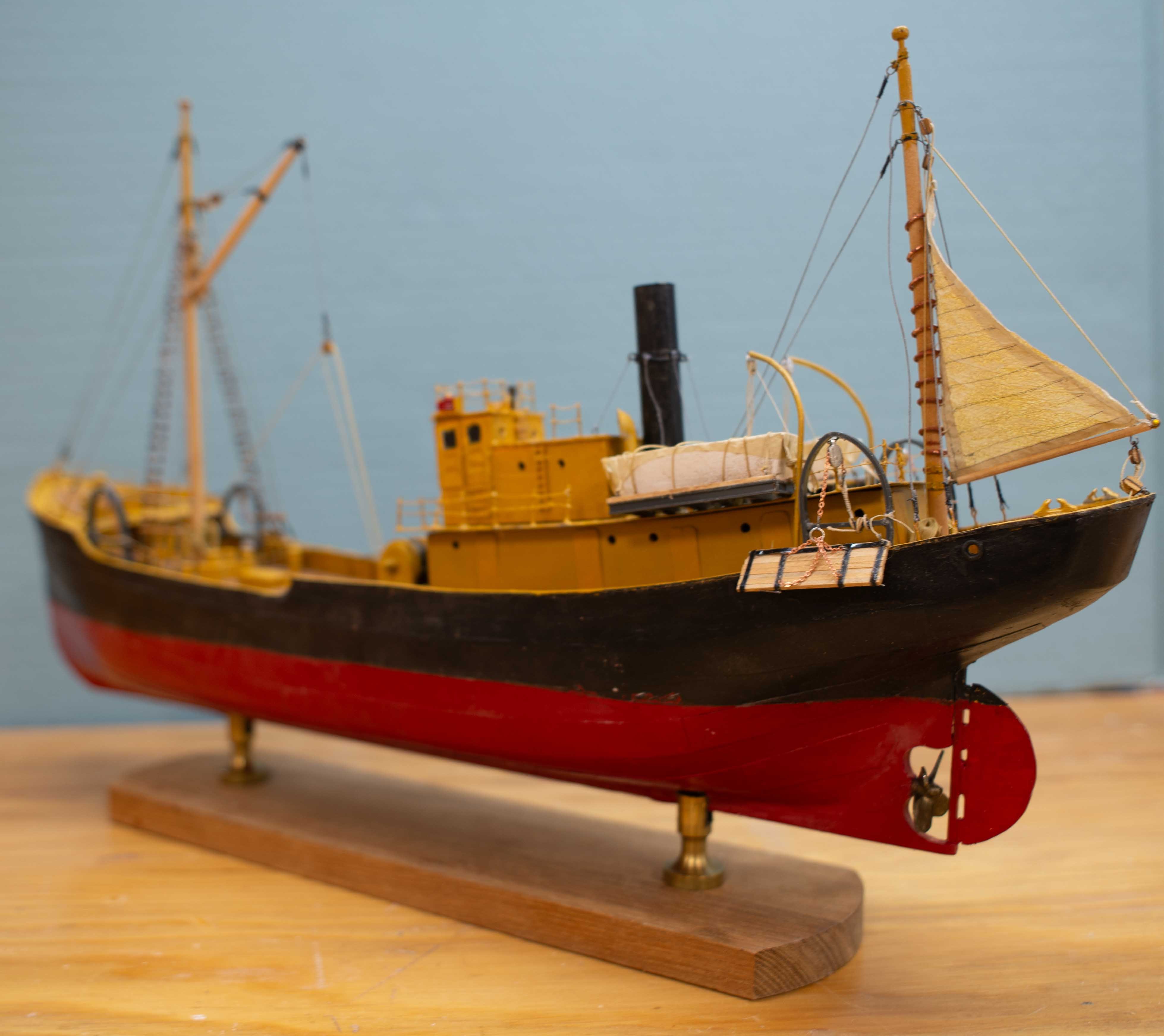
It has been a while since i last updated this log, and now I am planning another build, so I thought I needed to add the display photos of the completed model and close this log.
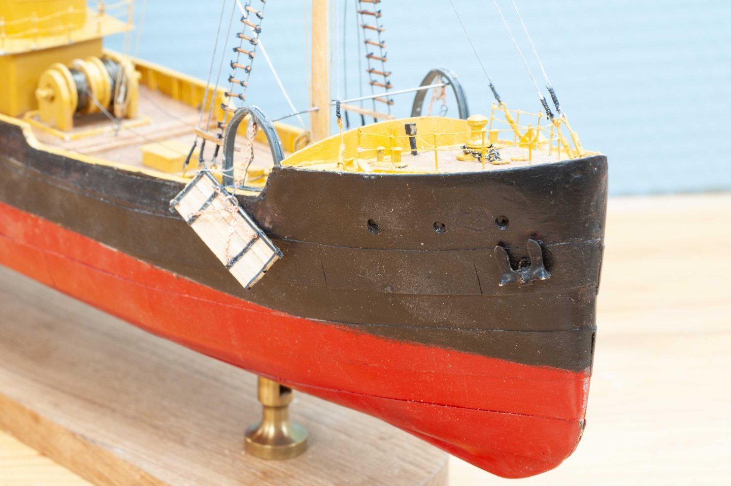
I include a batch of 10 photos I took a while back. Unfortunately the crew had not yet arrived.
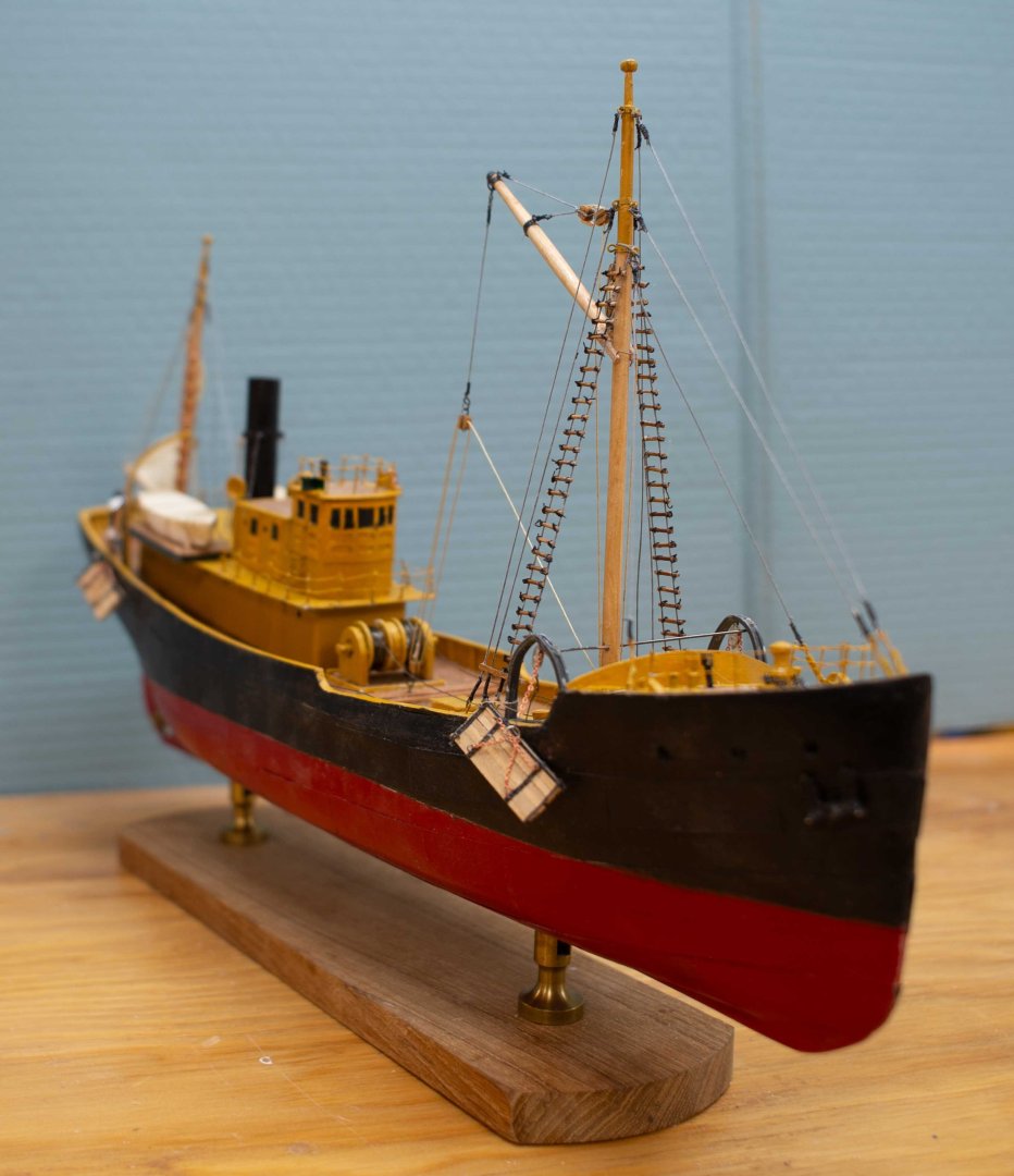


This summer we are celebrating the Rice Brothers shipyard at the local Boothbay Region Historical Society. As I have shared in the log previously, I have been meeting regularly with Robert Rice the last living heir and grandson of the founding brother Henry. Robert has also donated much of his work to the society this spring.
Here are 2 photos of the combined display showing his three Models along with my two. I will give a talk in July and then it will be done.Here are views of the combine collection and my contribution.

on to the next one...Jon
-
Jerome
thank you for sharing that great reference. the more I look, the more I see i do not know much about fishing. One thing I learned through reading during this build is to visualize all those cables moving and fish jumping around on deck and the noise, the rolling and the cold and wet and the....it doesn't end. I am very grateful to drive about a mile to the local grocery store and find fresh fish right there.
I just received 18 3 ring binders chocked full of the complete Rice brothers collection and will be fully focused on going through those and making up a slide show / talk series on their incredible history for our local historical society. I hope I can do them justices.
cheers
jon.
- Roger Pellett and TBlack
-
2
-
11 deck work nearly done and it’s time for a punch list
This posting includes the part of my builds where I may be getting to the end of the model part but have a similar effort to put together the story to tell in the summer months. First up though let’s see how far we have come… Since last time I have focused on the rigging and the stern. Also, more research on both fishing and on the yard.
For planning I share three images-
1
 here is the fore mast as shown on the Rice brother’s plan. After looking at several photos of different versions of a dragger, I chose to follow these plans. I am still guessing if the hoist line from the boom as indicated is for two dropped blocks with the halyards back at the mast, of if the single line aimed midship is the one halyard going down near the winch. There was a smaller winch I believe connected to the ice chopper forward of the foremast, so I may take the lines there. I am not sure the big winch running this line would make much sense.
-
2
 here is the mizzen mast. It is quite simple compared to others and I plan to keep it that way and add a sail for fun.
-
3
 In my continued research of the yard, I found this great image of the dragger Fabia, she was a wooden dragger 132 feet built by Brother Frank Rice next door in 1920. I share her to show quite a variation in rigging and only built 100 feet away. Thus, my decision to stick to the plans.
Work update. Here we are today looking at the rigging-
4
 looking at the foremast I need to complete the ratlines, mast light and figure out the hoisting lines.
-
5
 looking at the mizzen we see our sail is up . I used grey thread for galvanized cables; lighter weight with no turnbuckles for the stack.
-
6
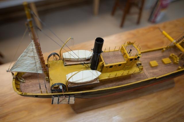 looking amidship we see the boats. Based on the photos they are on raised platforms pushed out to the bulwark line. This platform also provided a little more cover on the working deck. I found the idea of a single davit interesting and challenging for the users.
A few details....Thanks to Jerome I did not continue with rope for the main two net lines. I chose to use thin annealed steel to give the look that was closer to spun steel. The problem with my limited skills is how to make it tight enough to look like it is in tension.
-
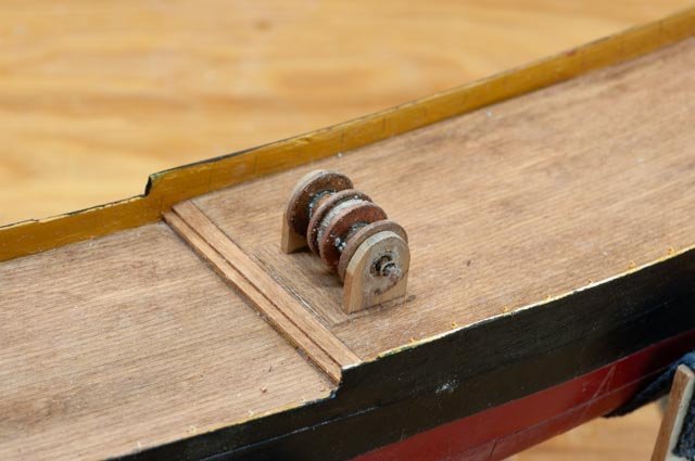
7
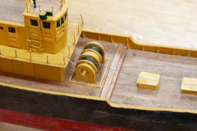 here we are on the reels. At a larger scale I might have tried braided picture hanging cable of some type of fishing leader.
-
8
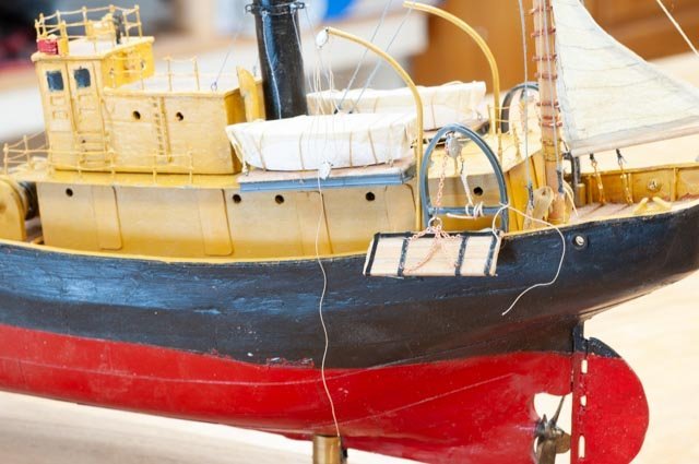
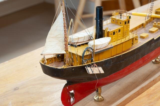 here we are with the active otter board on the starboard quarter.
-
9
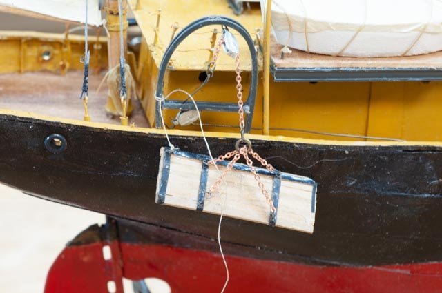 close up… It is still loose, and I need to figure what to do with copper chain etc. I ran out of good black tape and the shiny piece is awful.
-
10.
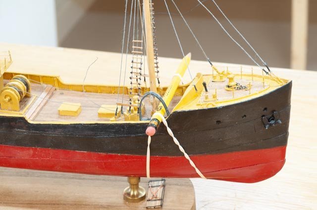
 This view is the inactive side and I am making the solution up. I spliced a heavy line to hold the otter board overboard on this inactive side.
-
11
 here up forward I am gluing down the active gallows frame.
-
12.
 looking at the fore deck we see the cables are steel but a bit loose. I also need to figure out the ice machine foreword of the mast. I have decided not to include in this build......a guess at what the checkerboard type set up of compartments for sorting fish, missing quarter lines that would go from the end winches through multiple sheaves to the center of the net, stored net on deck[ after deck read], or any fish. I do, however, have a few figures and it is always fun to place them aboard too.
The punch list is really straightforward. I will be shifting more time into preparing the powerpoint story, so the model and story are done in the spring. Being me however, I will start another build by then too.
All for now. -
1
-
Nils
thank you for your kind comment. I regularly watch your work and I must say it inspires me especially at this small scale.
cheers
-
thank you John and Jerome
Jerome you caught me just in time. I was already yesterday to connect the first line to the otter board chain at the aft gallows. Now I need to decide how best to replicate used but not rusty steel cable, I used the grey thread for galvanized shrouds and stays. If I use black, where is the shine. Perhaps it it new? I will think on it but not too hard...smile I appreciate the catch however and the "rope" will go away.
cheers
-
10 update on the deck work
This update does not reach any milestone; it just ticks a few more boxes. I wanted to start forward and work my way aft. I must say reading more about these trawlers simply amazes me about how tough the work was, and in some cases still must be. What I hope to show will cover the main control of the nets. I have looked at several photos but keep going back to the Rice Brothers plan when deciding what to build.
-
1
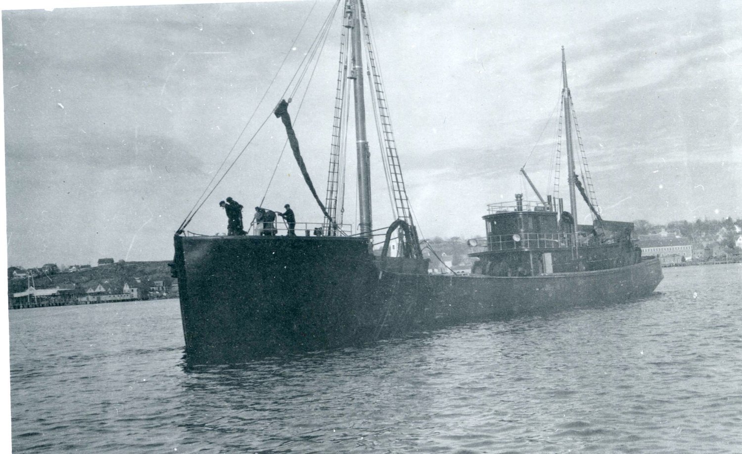
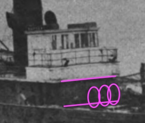 here is the blow up of our only photo of Harvard as a fishing vessel. The ovals are looking in the shadows to determine the size of the main cable reels.
-
2
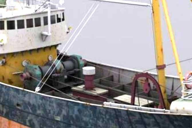 this image is another internet sourced photo of an older beam trawler. The reels seem a bit smaller, but the lines are clearly steel cable.
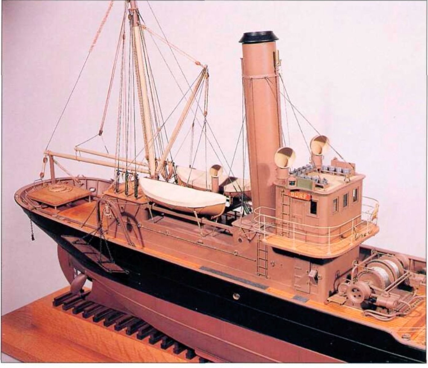
I don’t plan to include more images from the 1912 model by Erik Ronnberg but there is much information on how these things were set up and his interpretation of a deck lay out. He pointed out that he too had no deck drawings and few useful photos to use. His diagrams and explanation though were incredible as usual, and they make up my limited understanding.
-
3
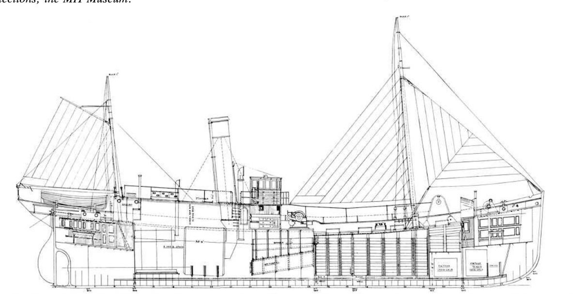
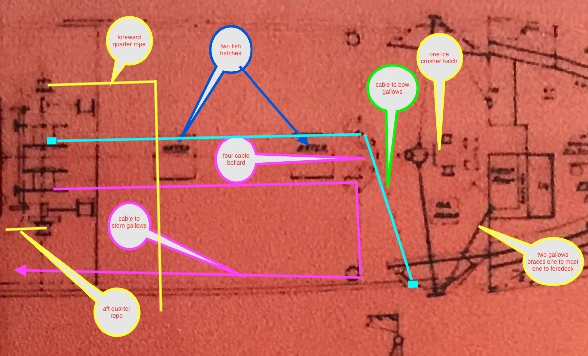 here is a blow up of the Rice Brothers drawing that I have annotated. I felt I could do that after reading all of Erik’s articles, so I gained a beginner’s knowledge.
Differences from his conclusion include:
• The side bollards to take the main cable aft to the aft gallows are forward and parallel to the main four bollards. Set up is the same for the 4 main bollards.
• There were two fish hatches not one.
• The gallows braces go to the mast and fore deck as there is no center cabin enclosing the foremast.
• The ice crusher/ hatch is forward of the mast.
Similarity includes…. I plan to assume rope for the main lines. If I learn that I am wrong I will hopefully be able to paint the exposed line dark to simulate ugly used steel cable…..smile.back to work
-
4
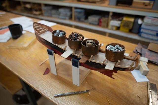
 to make the reels I fell back to my non machinist approach that started making winches on the Boothbay Harbor One Design RC racing sloops I built years ago at 1:24 scale. Copper and brass washers of multiple sizes. The small end winches for the quarter ropes are two open brass open rivets. The shaft is combination of nested brass tubes going from the smallest holding the rivets to the largest holding the washers. There was flux and stuff all over it after soldering so I dropped it in a pickling bath thinking it would clean up. Oops that was not the right solution….see the salting. Anyway, after several attempts they cleaned up. I used Costello wood for the end frames.
-
5
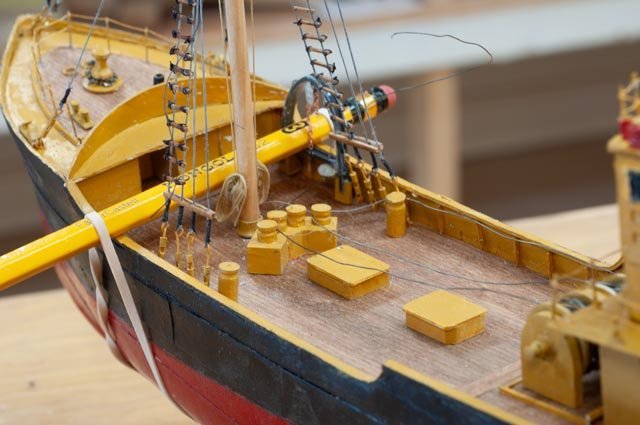
 here is an overview of the large reels with rope coiled. The two hatches are in; just styrene on a block. The bollards are turned dowels set into a small block of poplar.
-
6.
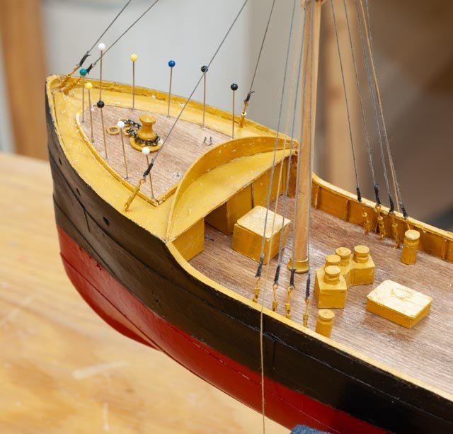 looking forward my rail method of cut off pins and tied painted line is clear to see. I am not ready to electro or is it resistance solder tiny pieces, so hopefully this method continues to work for me. The block for the ice crusher is a place holder now. The gallows are under way and are the main feature to come next. I was glad to read that the name breakwater is the right name for the curved plate.
-
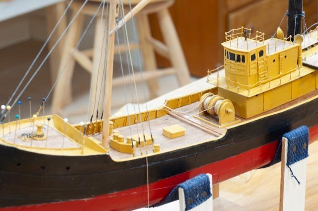
7.
 just an overall shot. The cabins are in place, the rigging has started and the after deck work is next.
All for now
-
1
-
9 fore deck and cabin work
As we complete 2023, I wanted to have the basic “canvas” [ hull, decks, and cabins] done so next year I can focus on learning how they fished and what a trawler was all about. I also wanted to fit my work into the story I am forming to tell next summer to include the work of the Rice Brothers and how their inspiration of introducing steel hulls made such a change to this market. Meeting with Robert Rice, heir to the famous shipyard, has opened an incredible source. One example is how he helped me decide on one of the options I shared in making alternate mockups for the main cabin/ pilot house. As I previously posted, I was wondering about the difference in the shipyard drawing with the undated photo of Harvard within which there is a raised platform around the deck house. Robert told me that in the earlier days, unlike today, changes to the work in mid-stream were less often and less significant. Looking at the Harvard photo he concurred that the platform was likely a later change, not original. I decided not to add the raised platform around the pilot house. That decision also means I am most likely keeping the build to match the other draggers of the same design built earlier, 1918-1921 in the same yard.
I share below my process to decide then build the foredeck and cabins.
-
1
 here is a great drawing from the Erik Ronnberg article explaining the cross section of the typical dragger of this size and era. I note the fore cabin for the crew in this version goes fully below the main deck level. In the Rice Brothers drawing the crew quarters are all above the main deck. The plan here raises the foredeck with a rounded deck line [ seen is previous posted photos] . it is not the same. Also confirmed with Robert Rice the Boothbay built draggers did not have aft below deck captain cabins.
-
2
 here is the Rice Bros drawing. We see the portholes and the full height of the deck. There is a rail and a breakwater [ not sure of the breakwater is the right name of that feature, same as on lightship], and the anchor winch.
-
3
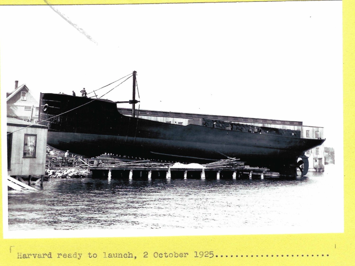
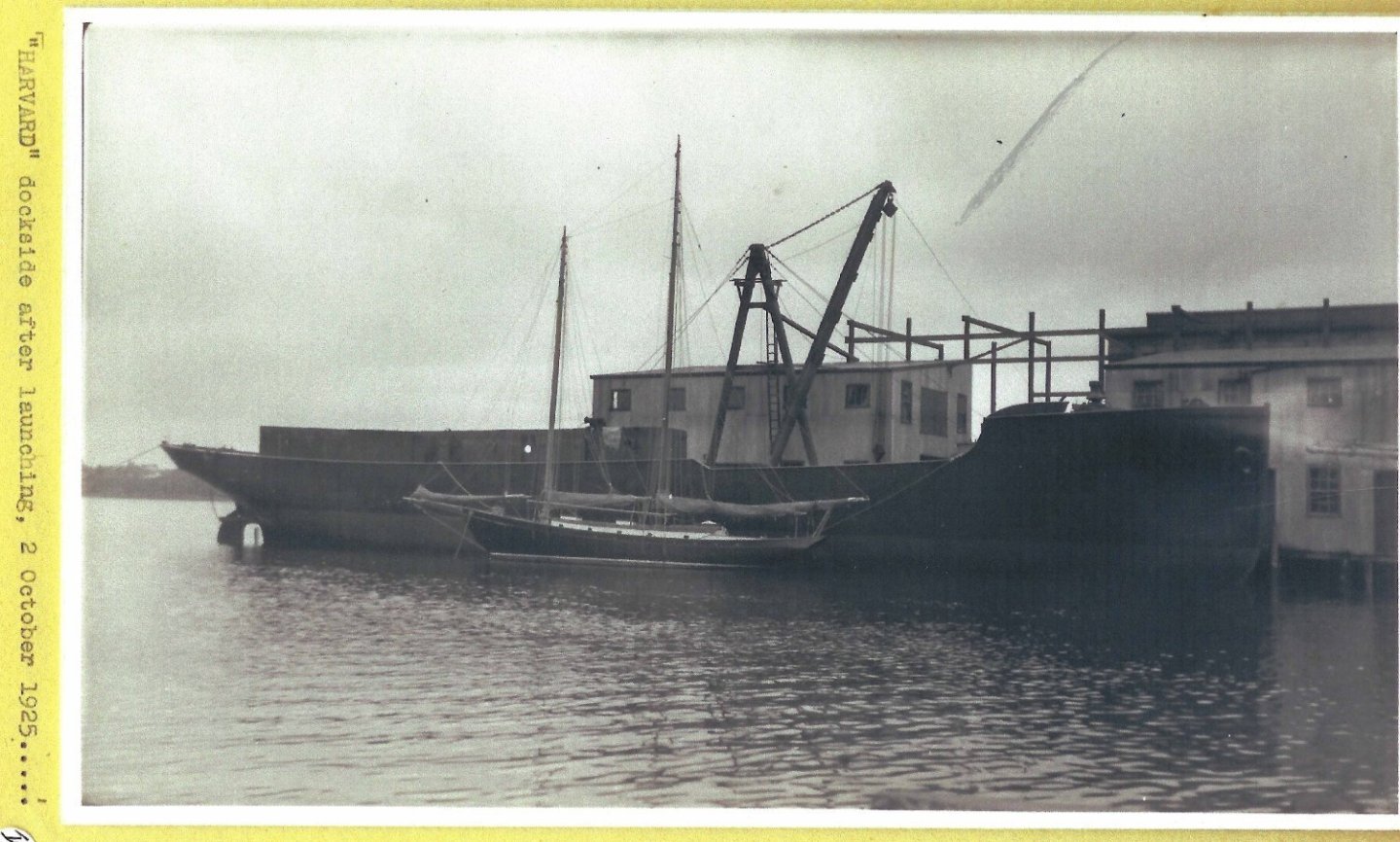 here is the Harvard alongside the dock after launch. The high square foredeck is clear.
-
4
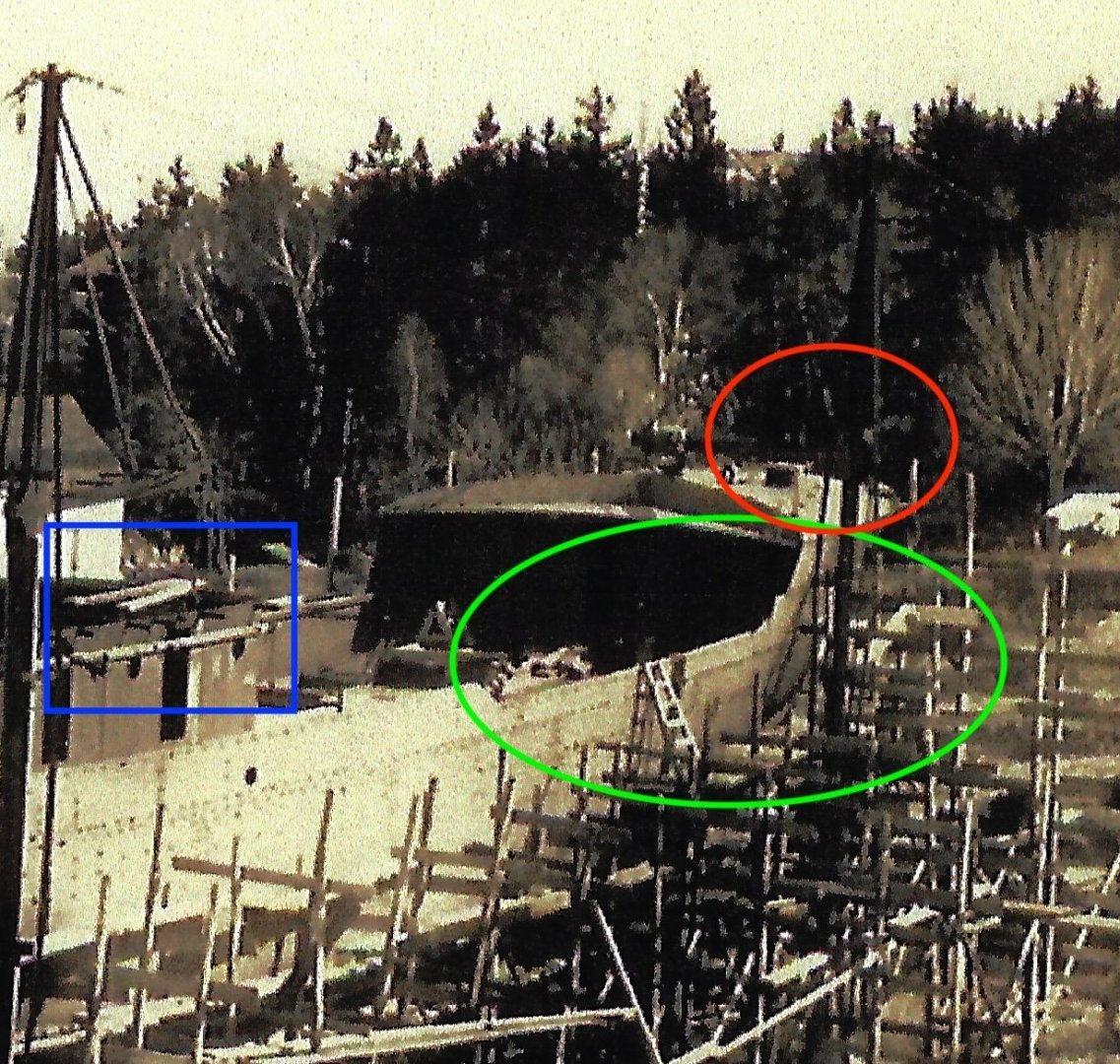 here it is hard to see, but I believe visible enough to clarify three points.
- Red oval: the fore deck has rails and wood surface in the center and curved breakwater just like the Ronnberg model that I shared in an earlier post.
- Green oval: the profile of the bulwarks is what I am trying to follow. The raised deck starts before the main cabin running aft as the bulwark suggests.
- Blue rectangle shows the configuration of the lower main cabin in steel with brackets for the top deck.
-
5.
 here is the Rice brother’s drawing cropped for the cabin profile and deck rails. I used this for the build.
To work
I decided to make the upper deck, stack and rail stanchions using brass.
-
6.
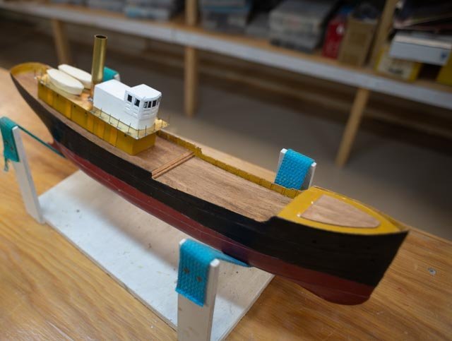 here is a dry fit. Also noted the wood decking portion of the foredeck.
-
7
 in this closer view the styrene angles are used for the bulkhead stanchions. I use the angle not because I know that it’s right, it just looks more like steel and not wood.
- 8. ,9. Here are two New Year’s progress photos.
-
Looking forward I need to learn more about how the draggers worked.
Happy New year
- mcb, GrandpaPhil, Mirabell61 and 4 others
-
7
-
1
-
8 progress on the hull
Just a few bits of progress heading to the end of the year. I need to complete the stern and bow and then with a sub deck in place get the bulwarks done.
-
1
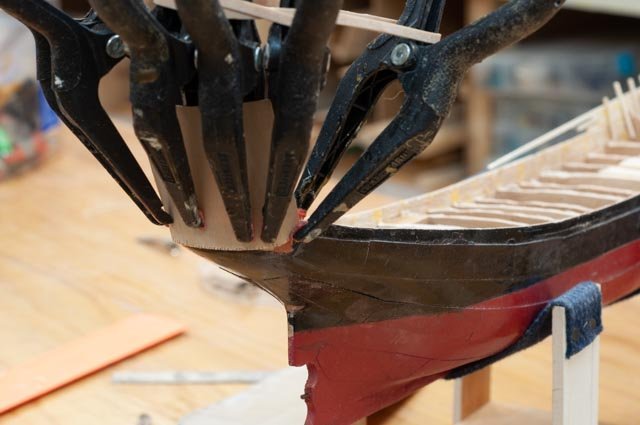 here I am building up the fantail using 1/64-inch plywood.
-
2
 as we see clamping is tricky.
-
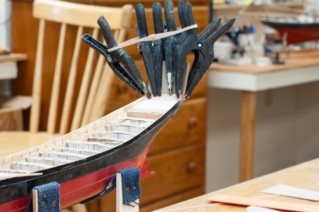
3
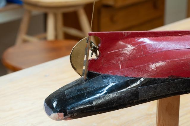
 here I am building up the bow. I have chosen to follow the photos of the real Harvard at launch.
-
4
 here is the Erik Ronnberg bow. Note the rounded affect. I like the wood deck insert but do not follow this curved profile.
-
5
 here we see Harvard being launched and the fore deck is clearly as high as a man. A second meaning is there is clearly room for the crew area under the foredeck. The design drawing I have varies a bit but includes three portholes for three births in this area.
As I mentioned before, I was not happy with my first rudder assembly as it ended up off center. This new set up used the aluminum foil to raise the little tube gudgeons and rudder hopefully to meet the centerline of the post.
-
6
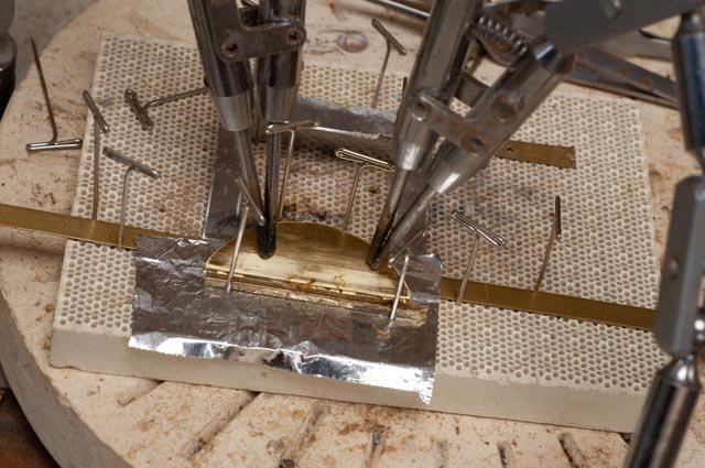 here is the set up. It came out better, but still not on center. I may go one more time to try to get this right.
Now time for the sub deck and bulwarks. As I shared before I goofed by making the bulkheads too high in such a small model. I roughed them down and to recover and decided to cheat. I added a 1/64 plywood sub deck to mitigate the issue.
-
7
 here we are gluing down the plywood sub deck.
-
8
 in this view I am gluing on the reraised bulwarks to meet the profile.
And here are two photos for the xmas progress.
-
9,
-
10
 the little wood blocks are still mock ups of configurations from different sources, since I have yet to find good photos of the completed vessel. I am still looking. I also have confirmed in the photos, but not the drawing, that there was a breakwater across the top of the fore deck to hold back water from coming on board. The question is, was that installed when built or added later. More on that subject next time
Happy Holidays
- ccoyle, FriedClams, JacquesCousteau and 3 others
-
6
-
1
-
07 what should the deck house look like?
The last week has included more searching while I peck away at completing the hull. I received a few pieces from my friends at Bluejacket, so we can add anchors and the like. I am also fretting over my deck support dilemma. I am trying out a short cut and will see if it works......
-
1
 First up…. here is photo of the construction paper on the hull before paint that I forgot I had taken before painting. It should have been in the last posting.
-
2
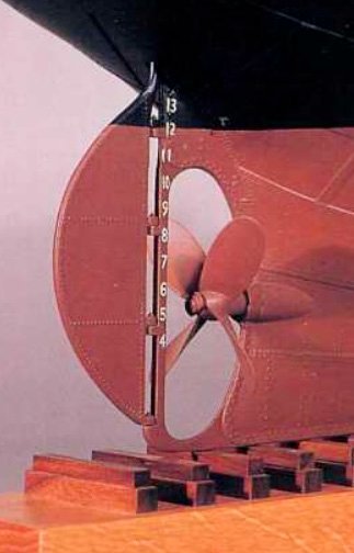 Second... we look at the master’s Erik Ronnberg rudder and propeller.
-
3.
 Here is my first attempt. It came out with some defects that I will have to rebuild. I need to figure out a really thin shim that will not attract solder to hold the rudder at the center of the thicker post. I had set a aluminum sheet under the brass rudder , but unfortunately, I ended up with the rudder off center…opps I share the good side …smile
Now to the study of deck house
-
4
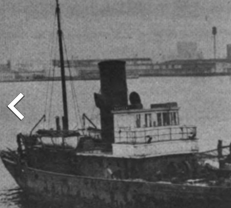 here we see a blow up of the only photo I have been able to find of Harvard in at some point in her 20 year fishing career. Note the platform surrounding the pilot house. It looks like the top level roof goes back toward the stack [. This is the critical point discussed below]
-
5.
 this view is blow up of the Erik Ronnberg model of similar design. The pilot house is very small, no captain cabin behind. The lower-level cabin is much in head room etc., and the stack is forward and through the deck house. The view is invaluable for detail but not our configuration.
-
6
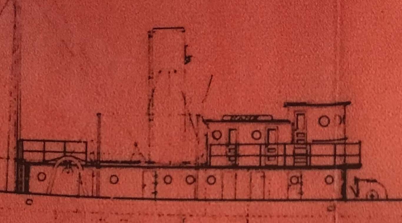 this blow up is from the 1920 +/_ Rice Bros drawing for the four trawlers. It should be noted that they were launched 1919-21. There was a recession in 1920 and many fishing companies were in trouble and cancelled orders. It was not until 1925 that Harvard was contracted again and was completed. Thus, it would have been possible for a different configuration. The two capt and mate cabins may have been squeezed it. It is hard to determine from the photo. The whole upper level was raised and I feel it is clear it ran aft behind the pilot house door, but for one or two cabins would be a guess on my part.
-
7
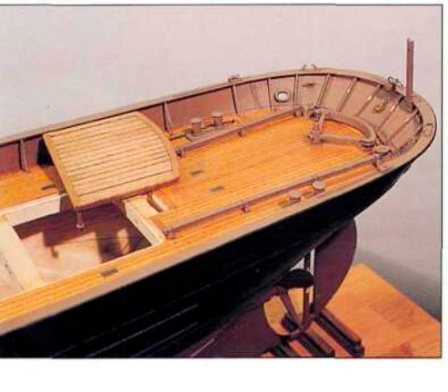
 finally here is a photo of a trawler at Maine maritime Museum. I find it interesting of the similarity. It clearly includes a captain’s cabin behind the pilot house. It also has a small second cabin behind. We are definitely in the right family of vessels.
Now what to do??
-
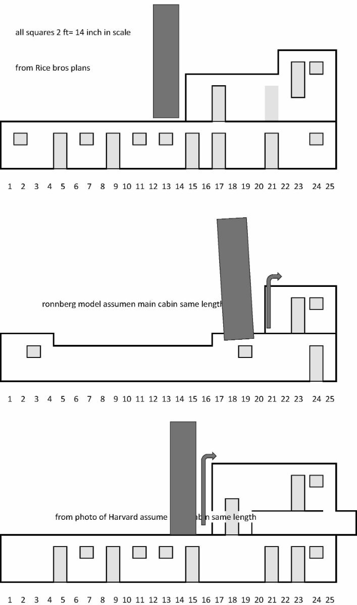
8
 here is sketch showing the three options. I have determined to follow the plan for the long complete Lower deck house as drawn. There may be a variation in doors, but something needs to be decided.
-
9
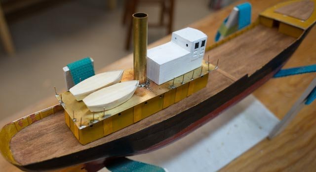
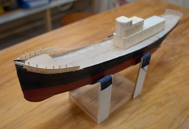 here is a mockup of what the configuration would be if I build to the plan.
-
10
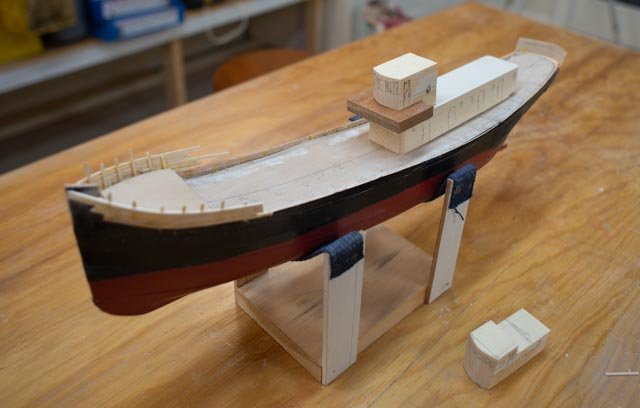 here is a mockup of what the configuration would be if I build to the photo.
I will need to decide which way to go. I will have access to more of Robert Rice documents soon I hope, and that, along with talks with Robert will be used for my decision. In the meantime, I need to continue to peck away at the hull, solve the deck so i can get the bulwarks figured out. The fantail has been roughed in with 1/64 plywood. I need to see if I can make that work too.
plus it is the holidays
cheers
- Valeriy V, GrandpaPhil, FriedClams and 2 others
-
5
-
1
-
Thank you Gary and Roger
Gary. watching your builds inspires us amateurs to give fishing vessels a try. the big winch that runs everything is well over my pay grade and will take some more study.
Roger I have a friend here who is a machinist and he said to me he uses both, so I am sure I will be off to Amazon again for a sponge. My brass rudder is off center, as the aliuminum shim was too thick, so I will show the good side in the next post but know I need to re build it....smile
cheers
-
6 let’s figure out the top rails and hull plating.
Sometimes I think I am so smart… then I suffer. In this build I made the top of all the bulkheads to be at the deck line. I used this method in larger models where one has reasonable access to sand, remeasure and adjust. I was thinking this is a shortcut, as the deck can then just sit there. Well, it was not that smart. Unlike a 4-foot RC sailor with 10-inch-wide deck, or even a 27-inch schooner with 5 inch beam, I have less than 3 inches across the deck. There is no convenient way to get in there with control to sand down multiple bulkheads for that nice surface needed to directly place the decking. If I had made them all just 1/8” lower, I could have made up deep deck beams and glued them to one of each bulkhead. In one day, all would have been done. Now who knows…
In the meantime, we need to figure out where we raise the bulwarks to fit the profile and set top rails. We have several sources to use:
• The Ronnberg profile drawing is our starting point. The rounded “domed” fore deck shown in his work was not evident in the photos of the Maine Trawlers
• The Rice Brothers photos are the goal. A few adjustments may be good enough.
• Internet photos of Harvard then Bellefonte then Albatross III. Unfortunately, the vessel was extended 20+ feet all in the forward area so interpretation is required.These all together should however be enough to cry uncle.
-
1
 here is the detail line drawing from the Ronnberg article that sets the designed bulwark dimensions for vessel. I have annotated a few elements to give heights for the bulwarks. The deck line is also shown on the profile drawing to check as well.
-
2
 here is a detail photo of the Ronnberg model trawler fantail. Mine will never look this good but it is something to aspire too. I thought I would first try to do this in 1/64 birch plywood and if no good, do it in styrene. Let’s see where it goes.
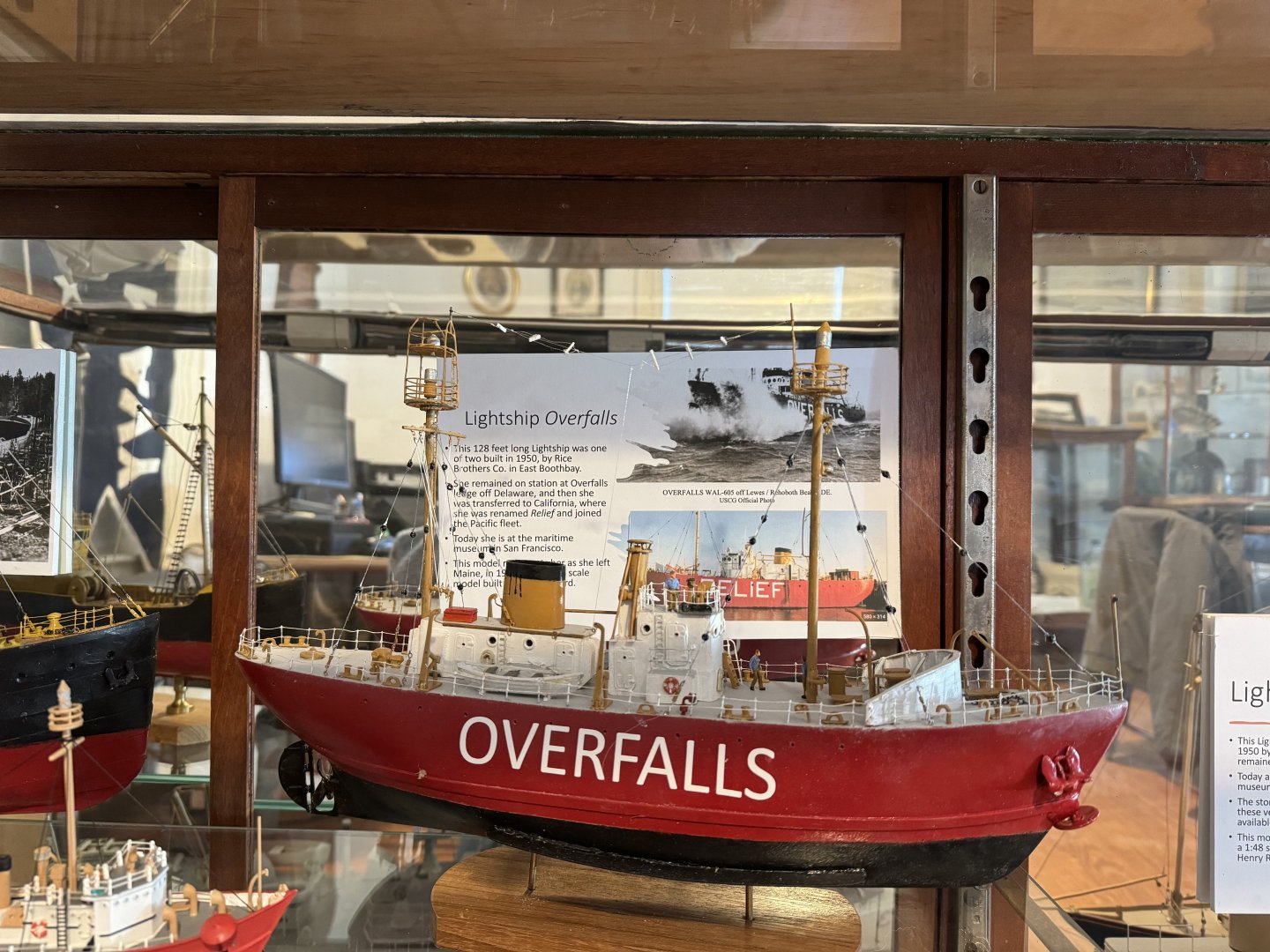
Just last week I began a series of interviews with Robert Rice. At 85, he is the last remaining Rice brother heir that worked in the plant around 1950. He chose not to stay there, and he spent 28 years in the army. When he retired in 1976 and began building houses. After a few years, he realized no one had memorialized the family history. He decided to do that and spent the next 40 years accomplishing an amazing library of photos, models and records. He joined with Jim Stevens, an East Boothbay Shipbuilder in his own right, who started the local Boothbay Region Historical Society where much of their work resides. In his home he has a 5-foot shelf of photo and memorabilia albums showing every vessel. He has great models too. He looked at the model I recently made of the Lightship Overfalls and instantly showed me an error…oops. I will post that over on that log next week as it is fun, and I will include a photo of his model of Columbia and the story of the major design changes that Rice Brothers had done to the two ships built around 1950.Back to the trawlers. Quite a story.
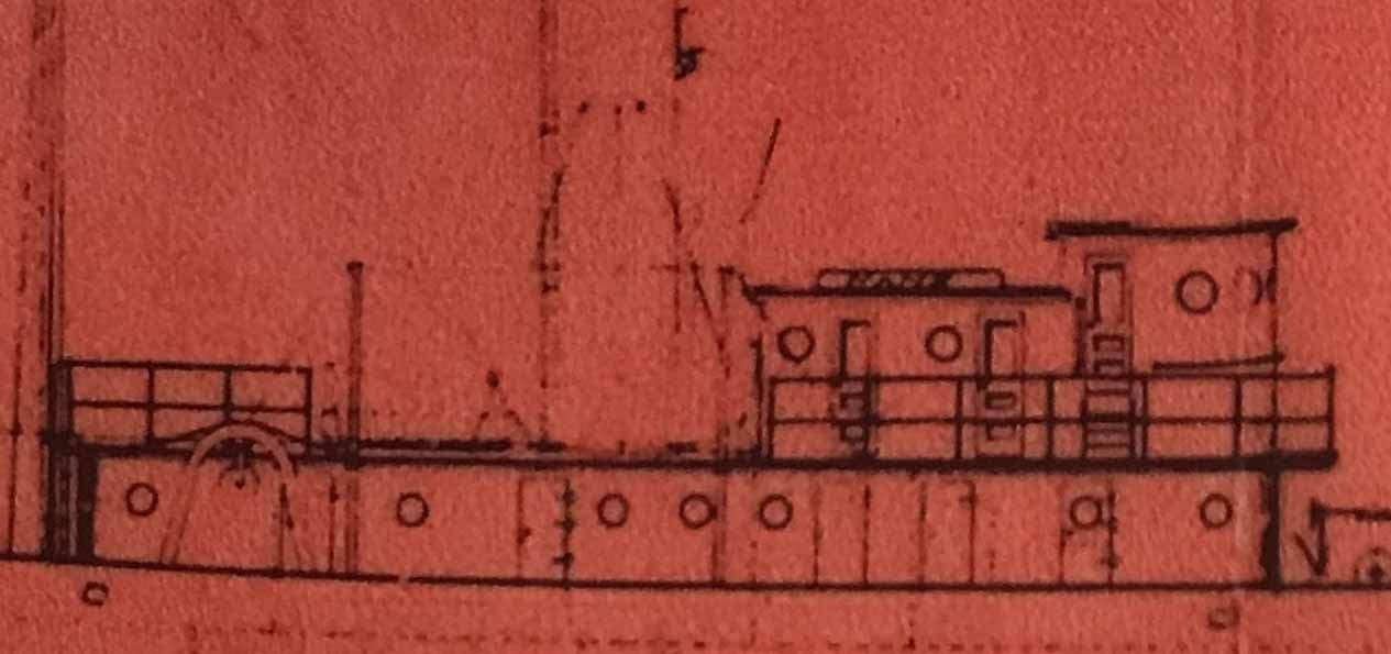
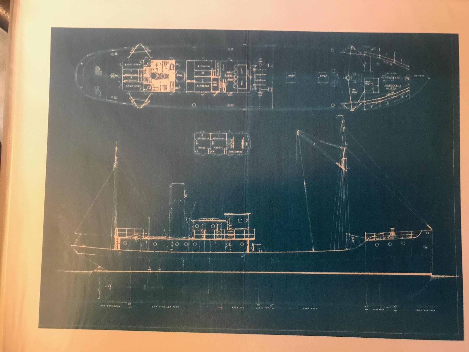
Jacob Stevens, who a few years later opened his own yard, was working as the designer for Rice brothers when they won these Trawler contracts and the first lightship Poe. Unfortunately, a fire in 1951 destroyed all the stored drawings. A few survived including a profile and deck plan for these trawlers. I include here a photo of the photo in Robert’s album of the Beam trawler blueprint profile. There were 6 variations of them built but here is the plan…..wow what a find.
-
3
 the plan profile as developed by Jacob Stevens who worked at Rice bothers for years before starting Goudy and Stevens yard in 1920-24
Now let’s do some comparisons. I cropped and blew up each portion to compare and plan.
-
4.
 here we see the bow area. I show both the Quincy Ma [ via Erik Ronnberg] cropped profile with the Robert Rice photo. I will do my best to replicate the Rice Bros drawing but note the lack of high foredeck visible in the photos.
-
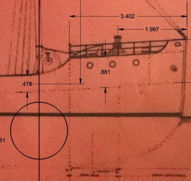
5
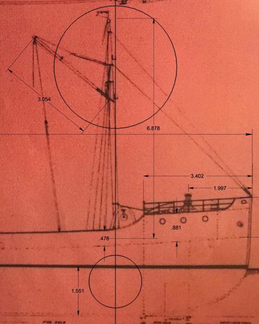
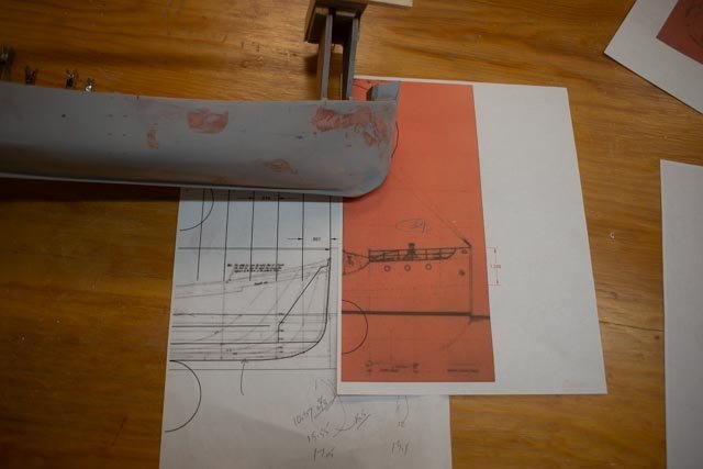
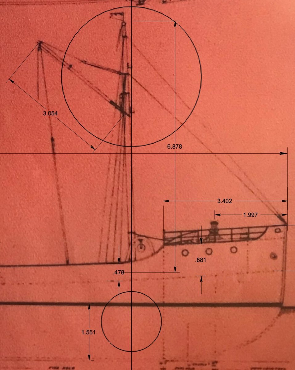
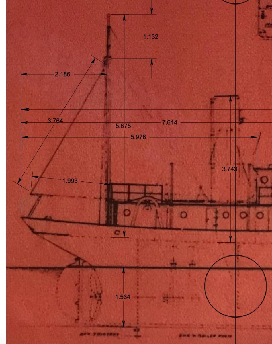
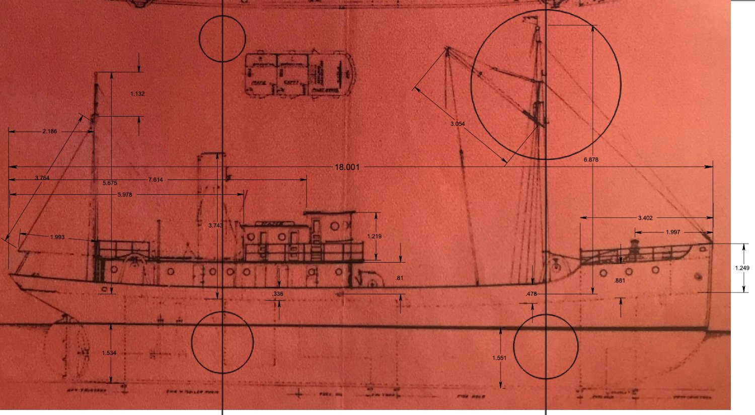
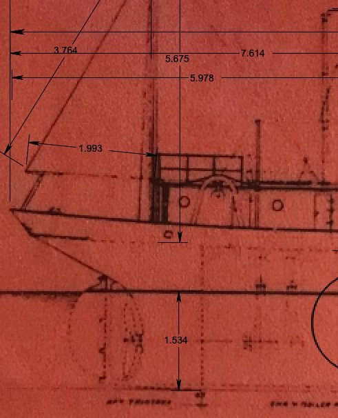 here we see the stern on a red color version of the blueprint Robert had. This red version is clearer, and I am using it for dimensions. I scaled it in Turbo Cad for that purpose. It seems the Rice Bros profile had less rise than what I have built. I need to acknowledge that, but we have followed the Quincy, Ma. lines and have what we have.
-
6.
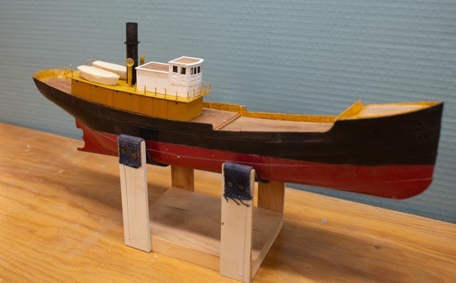
 here I share the whole profile. I am thrilled to now have drawings of the on-deck features to follow and that is key to getting where we want to be.
Any work going on?
If I have learned anything in the 10 years of this work is get the sequence right. I am trying to finish 4 things at the same time and some impact the others. I think I figured our my “path”.
-
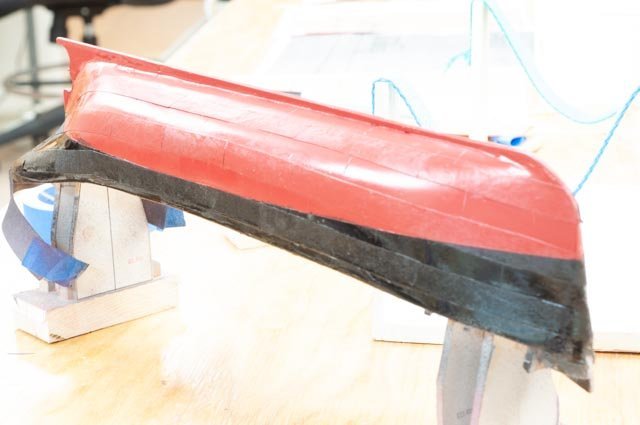
7
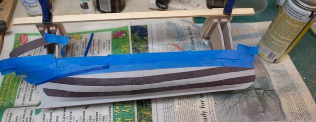
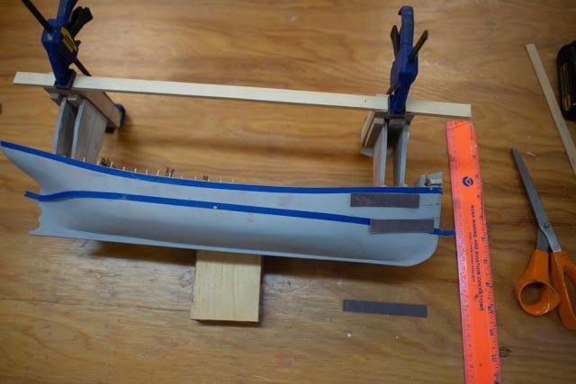 here we see the blue tape indicating the top of top outer plate. I cannot complete the added bulwarks until I remove the stands, as they are used to maintain the waterline dimension. The lower tape is the water line. I need to get the out plates on, then the waterline painted then remove the stands and complete fixing bulkheads for deck and bulwarks for rails.
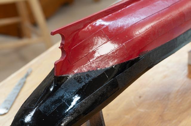
Following the tip from Roger, I bought spray shellac and applied it to construction paper before cutting strips on a paper cutter. I then cut both 8 foot and 12 foot in scale pieces and laid out the out “strakes”.[ not sure what one calls a line of plates]. I then cut vertical lines in the remaining hull to represent the same type plate spacing. I used simple diluted white glue to adhere the paper and then rattle can red and black. I suppose I could have applied a double layer of paper but decided at this scale not to do that. I would add plating to both inner and outer if trying 1:48 or bigger scale. Here in three pictures, we see the result. The Satin label on the cans failed me as there is a definite shine. We all know there will be another paint job after all the remaining work, so I will dull it down a bit.
-
8.
 stern view
-
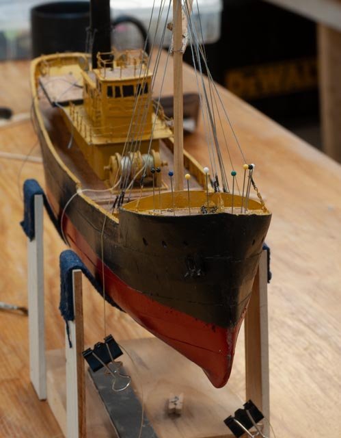
9
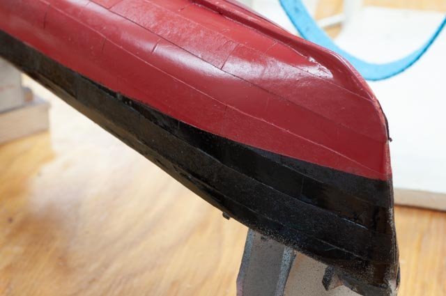 bow view
-
10.
 over exposed but whole view to see the plating.
Next up will be to complete the bow stern and raise the bulkheads and get ready for the deck.All for now
-
1
-
Andy. thanks and interesting. I have read several references as well that the big four,five six master schooners often needed tugs too. I recently learned of a whole new niche of schooner barges that combined old schooner and even ship hulls with the big tugs
tugs looks like they may deserve more headlines than they get . I ll save that rabbit hole for later.
back to fishing
-
thank you Roger Andy and John for dropping in
Roger.
following your work I have been watching a few more soldering tip videos. I have ordered a brass tip cleaner and when it comes will work on tinning and maybe some brass work. I currently work woth a blow torch. very amateur .
Andy
I agree with keeping a bit of a gas motor before heading out too far.....
the anxiety reminds me of Robert Perry who had chartered a steam powered bark named Windward for his 1898 voyage. under power it only did 3 knots so he waved good by in New York city and took the train to Sydney, Nova Scotia to meet up with her. Early stream did not enhance travel speed in sail other than with no wind or direction etc. I agree with your thought that perhaps fishermen were nervous to go cold turkey all engine. It is interesting if one simply googles trawlers and especially adding in the search "models" one quickly is in the world for sail power trawlers. hardy soles to say the least.
John.
would love to hear about trawling down under. did the market follow the British model and go to steam before 1900?
cheers
-
Roger
like many other of your followers I am reading your posts more than once. I am learning much as you tackle the many challenges of working to replicate on deck details. Your brass work is wonderful and inspiring. I may try a little.
the hatch covers introduced your use of the 'NRG thin rig guide , and has encouraged me to buy one. I find ripping less than say 3/32 against the normal guide from a sheet gets me some variation. Thanks for sharing that tip
jon
- mtaylor, Canute, Glen McGuire and 3 others
-
6
-
Thank you Andy Roger and Jerome.
Andy. there are images in the Erik Ronnberg articles that show sails fore and aft on the two masts. Those plans were for the Boston market 1905-1912. I will add those images later when I hopefully get to rigging. presumably they were for either stability or emergencies.
Roger. I remember being entertained and learning of the competition and jokes amongst Finn. vs Swede in that part of america. My relations were Swedes of Wisconsin and I had a college friend, a Finn from Minnesota. I am also holding my breath as I study your decision to go all brass above the deck in your build. wow.
Jerome. always a pleasure and I will be asking more help again once I get to go above the deck work. I may try some brass we'll see. I also have my supply of styrene.
cheers
-
Roger
Thank you for dropping in. Also, thanks again as it was your tip that got me to Erik Romberg’s articles. thanks for this hint as it answered my exact question.....I had read much of your blog previously ands went back last night to reread. Somehow [ though it was over a year ago] I had missed the entries you referred to here about using spray shellac on paper before installing. I did remember the part of having a bowl of warm water handy…funny how common sense helps. Wow great tip again and exactly what I am trying to figure out.
Running through your blog again and seeing all the great lake mariner’s input I have one too. My father-in-law grew up in Superior, Wisconsin. His dad was an ore boat captain named Anderson. My father-in-law learned to dislike the water and escaped first to college in southern Wisconsin and then moved to west Virginia in the 30’s. Then one day in 1940 he joined the navy and became the engineering officer on a tin can destroyer all over the Pacific. His stories were not filled with fond memories of Oceans.
Anyway, thanks for your help and inspiration through your own work.


Elizabeth Howard by Jond - 1:48 - The White Ghost - Schooner
in - Build logs for subjects built 1901 - Present Day
Posted
4 the yard and other related builds and starting the planking
One of the main reasons for my builds are to help illustrate the story of the local shipyards. So this build represents the Adams yard some 100 years in existence after family members began both in East Boothbay and North Boothbay. They were near their end in 1916, but first let’s see what was going on around us. Several issues were going on across the Maine industry
• In the big picture, the WWI commencement and success of German U-boats caused a dramatic need for large 4 masted schooners starting by 1917.
• The British trawling industry had evolved to steel hull and steam driven since the 1890’s. The American/ Boston market began that swing about 1908 ish. Rice brothers next door in East Boothbay had recruited a Naval architect from Bath Iron works and won a contract for a steel hull lightship in 1916. It would be followed by six steel draggers.
• Despite the war, the movement into Maine summer cottage life fueled the demand for Power and Sailing yachts that had blossomed since about 1895.
• The offshore fishing industry still had a need for large schooners and there were a few more years to go before the changeover to draggers.
• More yards in town were expanding into steam driven commercial and some private vessels. Marine engines of small to medium size were being built at Rice Brothers and installed in several yards.
• Maine yards were able to build John Alden, Crowninshield and other designed racing yachts more economically than southern New England., and that benefit steadily fed the local market.
So when New York client Mr. William W. Howard went to Thomas McManus for two new fast schooners, Boothbay was not surprisedly recommended. Adams like Hodgdon and Rice Brothers in East Boothbay and Reed and Townsend Railway in downtown Boothbay harbor were all busy. A few new lines were sketched onto on an existing 1908 drawing and Frank Adams, fourth generation builder, was off building another schooner. Though it was late in his carrier, he had a few more builds in him. The Elizabeth Howard and Louise Howard schooners were launched in 1916 and 1917. As fast sailors they would typically collect fish in Nova Scotia and race it south. Louise, a slightly shorter version, continued until 1925 when she went aground in the Carolinas.
Here are two images one with the steam boat that ended service in 1912. is an overall photo showing the Adams yard building a 4 masted schooner in 1903. Between then and 1916 the Rice Brothers yard to the far left expanded significantly to become the largest in Town. Adams continued to build both schooners and a mix of other vessels, and Hodgdon in the foreground , though since relocated, is today in its 5th generation
Progress
A little delay as summer has arrived. I just took a 3 week trio to see some of western Canada and buffalo at Teddy Roosevelt's National Park in North Dakota...much fun. We are now in the long planking sequence
Not unusual for me, I ran into an oops. My slitting saw blade, purchased from Byrnes several years back, did not really want to slice any more through even 1/8th popular. I said to myself no worries I’ll just use the normal 36 tooth carbide blade and chop up more wood. …oops wrong? Perhaps that blade is old too, but what I realized after setting several planks was that they were a bit rough. They had dings and undercuts….a true sign of my amateur status in milling.
I went online to find replacement blades and was very sorry to learn that Jim Byrnes had passed away. I was lucky to have met him once when he came to the NRJ conference, either in Mystic or New Bedford. His great attitude convinced me to try out his saw. It is great! Many of us are very lucky to have one.
I tried again to search blogs thinking I am not the only person who would like to find blades that have a ½ inch hole for the arbor. Even more unusual the little inserts to make other sizes reduce to ½ inch. Finally, a very recent post said the site as open to sell blades. I immediately got some on order.
In the meantime, I continued using “rough planks”. Fortunately, this model is all about white paint and I chose poplar for that reason. The extra dings and over cuts from that rough blade will eventually get hidden.
To catch up, here is the set up and first planks:
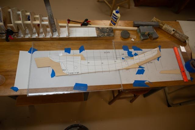
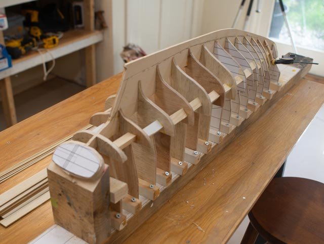
1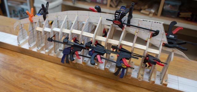 here is the alignment and fixing of the bulkheads to the “ keelson assy”
2. here is the built up transom
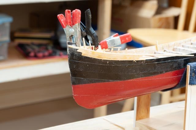
3. here is the roughed in bow block
4,5
6.7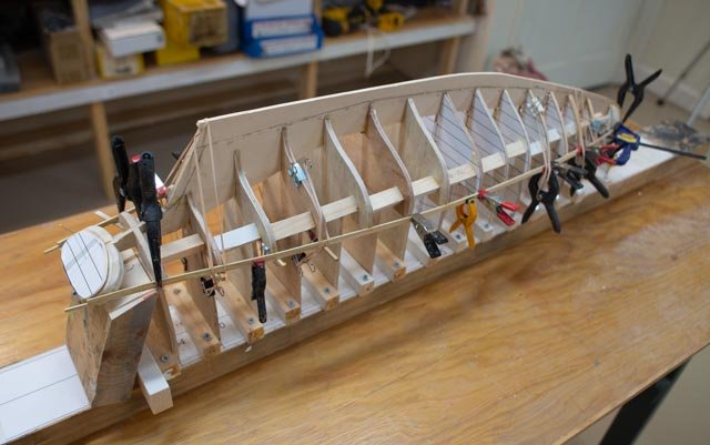
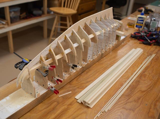
 tada the first plank.
8,9
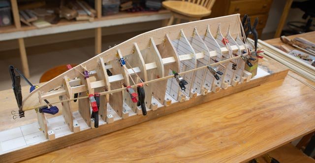
10.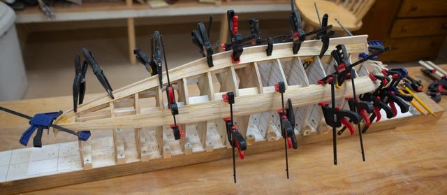 I leave with a picture only another model builder could enjoy. Almost every clamp I own is engaged.
Cheers