hexnut
-
Posts
406 -
Joined
-
Last visited
Content Type
Profiles
Forums
Gallery
Events
Everything posted by hexnut
-
J. Pett, many thanks! (Now, if I only had that "full edit" button on some of my modelling projects...) Garward, yes, the small size is the only negative that I have found so far. I haven't tried gluing it yet, I don't know how it reacts with CA or epoxy.
-
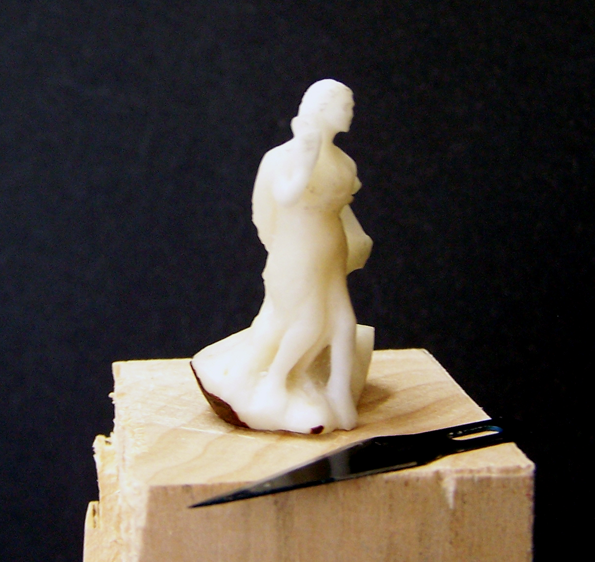
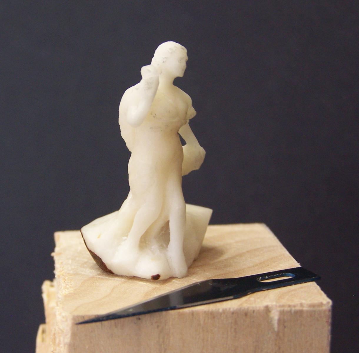
Janos, thank you for spelling "tagua" correctly, which I failed to do! ( I don't know how to edit the topic title ) I can't wait to see what someone with your skills can make with these things. Brian (RiverRat), I was mostly just experimenting with the material, so I played with everything from bandsaw, belt sander to a couple of different Dremel bits, but most of the detail work (so far) is just a #11 hobby blade, spot polishing with Micro-Mark sanding pads. Thanks, Anja! Brian C, yes, it's a Palm tree-type plant. This site gives a bit of an overview: http://dharmabeads.webs.com/taguanuthistory.htm
-
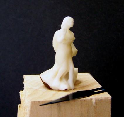
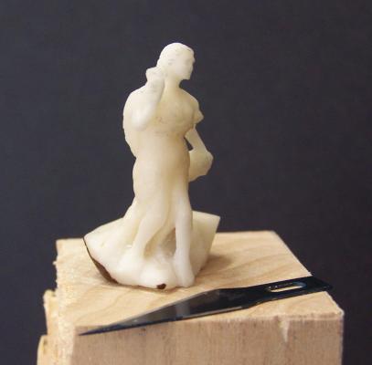
Thanks! The ones that I got in the bag were about 50mm (1.9") by about 30mm (1.2") The figure is roughly a vertical quarter of the nut. Now that I know the material a little better, I could get a larger object out of it, but I still don't think it would quite work out for a1/6 scale Cutty Sark figure head ... It also turns and machines very well at slow speeds, push it a bit and it starts to burn. (smells fantastic, like roasting coffee, but the surface will brown just like wood)
-
I'm not sure if this is the right place for this, but feel free to move it if I guessed wrong... Anyway, someone on this site mentioned tegua nuts, and I picked up a smaal bag of them at Woodcraft supply to mess with a bit. It turns out they are very freindly to carve, and will take a nice polish. I didn't get all that far, but I started roughing out a little figure of Amphitrite. (I had a tough time photographing it, my camera is getting pretty elderly.) The only draw back to the material, is that at least on the one I started with, there is a stem that goes pretty deep down the center of the nut and leaves a bit of a void. I had to modify the pose a bit to clear it. All in all, a really nice material, thanks for introducing me...

-
Great progress, Dee Dee, the planking is looking really good!
-
Please forgive my ignorance, but is "IPA" "Isopropyl Alchohol?" My Initial reading was "India Pale Ale", and I usually reserve that for soaking my insides, but if it is an essential modelling tool, perhaps I need more... The decking is looking really nice, I love the hatch work. Are your margin plank templates cardstock? or thin plastic?
-
At least we don't have to deal with Whitworth anymore... (Unless you are into old British machinery) Here's a great example from Wikipedia: British Morris and MG engines from 1923 to 1955 were built using metric threads but with bolt heads and nuts dimensioned for Whitworth spanners (wrenches) and sockets.[5] The background for this was that the engines were produced using machine tools of a previously French-owned company that was set up for metric production; for the average British motorist to be able to service his car, the bolt heads had to fit imperial-sized spanners.
-
1) I always thought that seeing a sign advertising: "3/8 drive metric socket sets" was hilarious, but the alternative would be replacing all of our ratchets, extensions and breaker bars... I have to admit that my professional life would be a lot easier if everyone just used metric, instead of the hodge-podge mixture depending on vendor and client that we have in the U.S. 2) I'd love to see someone hold 5 places on a Sherline or Micro-lux, or a sanding block--On second thought, after seeing some of the work posted here, some of you guys probably can...
-
Actually, for "vice versa", just multiply by .03937 (.04 if it's balsa )
-
Ships moored in Philly are having a tough time finding funding. After all that the Olympia has been going through...
-
Wow. I've always liked the look of this little schooner, and the work you are doing on this is elevating it much further! The completed deck looks like a much larger scale.
-
Great work on the rudder, Dee Dee, that looks really good. Keith, I think part of the problem is that I had the rudder turned a bit when I took that shot, although I think I did end up with a larger lower radius at the aft end. (Midwest just gives you a blank to glue to the edge of the keel, so all working parts need to be scratched.) The biggest problem I have with my rudder assy. is that the attachment point is way too low, Dee Dee gets much closer to Chappelle on that one. BTW, I think we are all using American Small Sailing Craft as a source because it's what we can get ahold of, does anyone know of other info sources? They supposedly have the MB sloop "Ranger" at the Penobscot Maritime Museum-- Has anyone seen it? Is this a picture of it? Whatever this boat is, it's pretty interesting with the staight stem, no cutwater and the shroudstays. I got it from here: http://byyb.org/gaffrig/200501/article%20craig%20milner.htm

-
I agree with Druxey, great to see the gallery art as well as the art you are creating with this build. Some of your sculpture has sort of an Isamo Noguchi feel to it, love the juxtaposition of organic and precisely crafted elements.. (Sorry, i will I get warning points for pretentious artspeak in a model ship forum? ) Anyway, really inspiring stuff!
-
That finish is beautiful. Did Herreshoff make any whaleboats?
-
Andy, thank you for posting the tracking sites. Fascinating, as well as providing further erosion to my already questionable work habits...
-
Thank you for reposting this. Your build is a gold standard for all of us aspiring Muscungi!
- 21 replies
-
- 1
-

-
- muscongus bay lobster smack
- midwest products
- (and 1 more)
-
HMS Lizard 1697
hexnut replied to igorcap's topic in CAD and 3D Modelling/Drafting Plans with Software
Very nice work! Thank you for the reference to sculptris, I had never heard of it before, I started playing with it after seeing your post. Pretty powerful, for a free download. It also exports nicely into Rhino. Do you ever use Poser for a starting point for human figures? -
Rhino did have a pretty big learning curve, but I've been using it for a long time now, so it's like an old pair of workboots. I'm sort of tied to what my clients can talk to. (Which is why I switched to Illustrator years ago, even though, as you pointed out, Corel does some things better.) Plus, I occasionally send stuff out for rapid prototyping, so I need watertight solids. I have to admit though, I learned surfacing on paper and foam blocks, so it's still the go-to for figuring stuff out.
-
Wow, this is some really nice work, I love the details in the oars and hatchet. You've probably already seen this, but I think it's cool how closely the 1:1 techniques resemble the modeling methods... http://whaleboats.blogspot.com/
-
Dee dee and Mario, thanks for all the help. Mario, you have already provided great inspiration for those of us stumbling along in your footsteps... Sea Dog, thanks for the compliment--I draw stuff as part of my job, so I'm pretty used to working things out visually.(pixels are cheaper than wood) Although I've already accumulated a large scrap pile for what is supposed to be a beginner kit. (No fault of the manufacturer, just my inability to leave well-enough alone.)
- 86 replies
-
- 1
-
-
- muscongus bay lobster smack
- Midwest Products
- (and 1 more)
-
Dee Dee, For rudder retention, maybe a block of wood or bar that picks up a groove in the shaft? It could be as simple as a swivel at the top of the post and a line with a tautline hitch into an eyebolt on the seat... Or maybe just a small set pin to pick up a groove at the bottom? Apparently, these boats were simply beached at low tide to work on them, so access might not be an issue. One very interesting thing I read in "The gaff rig handbook" by John Leather (available online) on p. 86, he talks about a "knife and comb" arrangement to lock the tiller at a given angle while luffing in to pull up lobster pots. You haven't found any pictures of such an arrangement, have you?
-
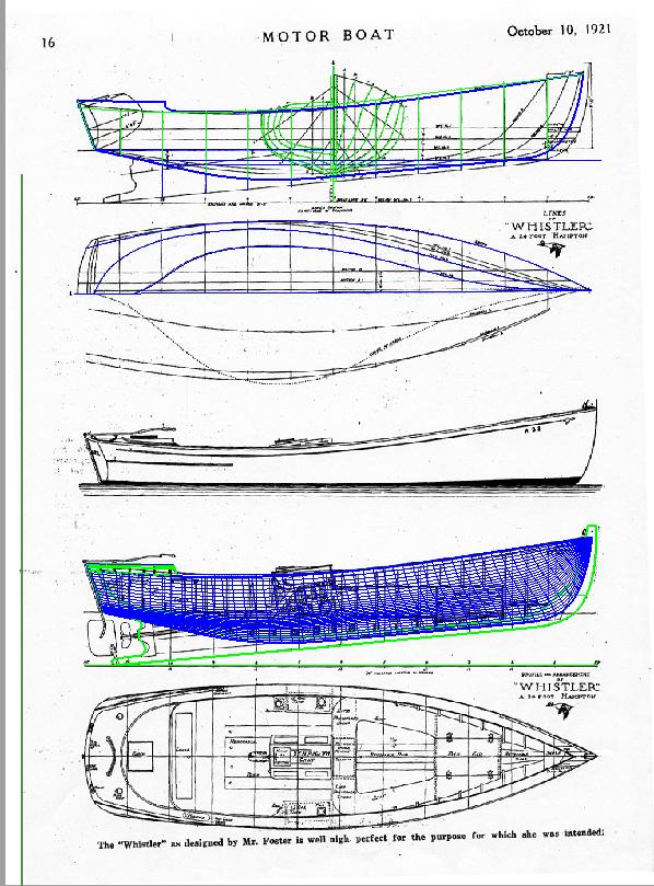
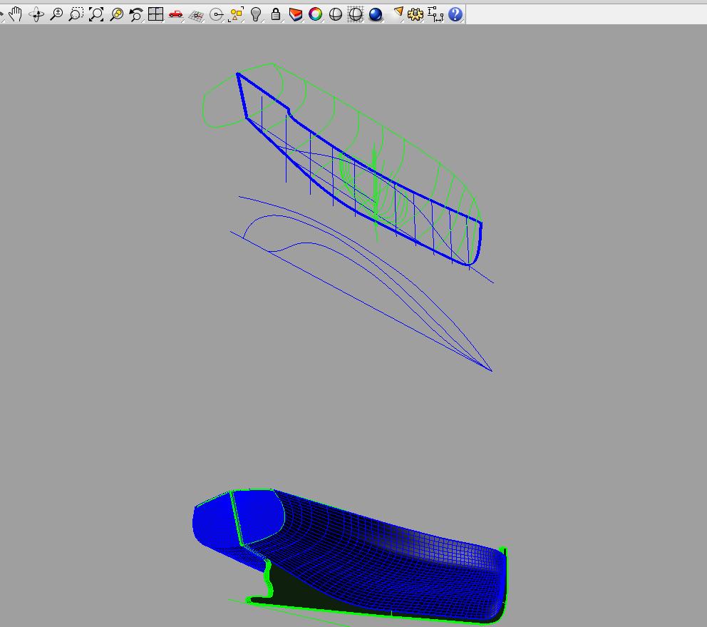
Michael, I'm glad that the pdf method worked for you. I do similar operations going back and forth from Adobe Illustrator and Rhino (3d cad). Illustrator is like Corel in many ways, it's great for scaling bitmap images to proper size, but not good at precision vector drwaing. Rhino has a "background bitmap" feature that allows me to import the prepared image (probably much like Russ's version of Acad) and the spline drawing is really nice. It also has a "fair command, so I can draw a bunch of stations, connect the dots, and then when I fair say, a gunwale edge, I can see where it pulls apart from the ends of the stations and what I need to tweak. I can then rough skin the surface to see where the glitches are, go back and fix the control curves. Rhino is about 1K usd, which is pretty good for useful 3-d cad, (but on the other hand that's a lot of wood) I use it for work, so hobby stuff is just a nice bonus... I started working on a trial run, the top are a scan of plans from an old magazine, the lower is vector lines and rough skeleton with a fair as I go rough surface development. You can see in the lower image where I have the aft stations reasonably well worked out, but you can see ugly creases and ridges where I have to add final stations along the fore. Of course, for me the big challenge is I don't know much about making wooden boats yet, I'm a bit freaked out by how some of these old plans are more basic guidelines than precisely-toleranced surfaces, I have to keep in mind that these things were hand-built and no two were exactly alike...


-
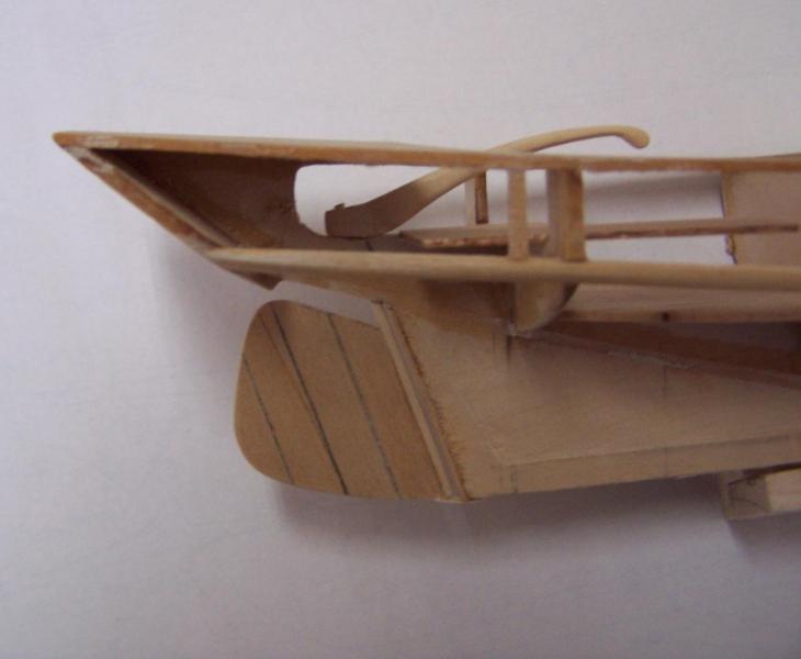
Awesome work, Dee Dee. Great tip about the cockpit floor. I especially like the way you handled the well hatches, positioning is much better than the stock locations. I've been dithering about it for weeks, now I think I will do more or less what you did. (You don't charge hefty royalty fees, do you?) As far as the rudder/tiller, It looks like you have it sorted by cutting away the "c" section aft of the stern seat. I also decided to upgrade after I had the deck and battens on, but there was still space to put a dremel end mill to hog out the area. (I also left a slight step so that the seat planks will end up flush.) I taped a short length of brass rod to the keel as a drill guide for the rudder pivot, grabbed the very end of the drill w/ the pinvise. Even though the angle had to deviate a bit from "true" to accomodate my pinvise, the slop won't be noticable once the lower pintle is installed. (I'm going to remove a portion of the keel for the angled pintle rest, right now it's just taped in place.) Do you think they used any gudgeons on these rudders, or just nailed cross plys?
-
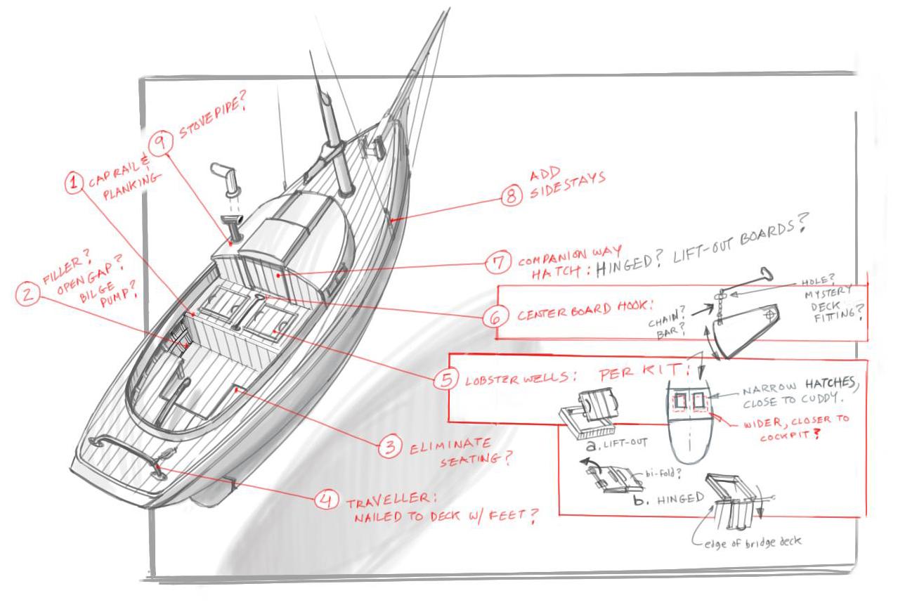
Thanks Keith, no, I don't think it ever stops... The canoe looks brilliant! (even before Al got in the act... ) Thanks, Dee Dee, I am very glad that you mentioned the fish wells, as those have been puzzling me. The ergonomics of putting in and removing fiesty lobsters from the kit hatch locations seems a bit sketchy, as they are very narrow and far forward of the workspace. They also seem like they would impede headroom for the bunk in the cuddy. I have heard the wells referred to as "pyramid-shaped", and the single well in Chapelle's Friendship sloop drawing seems to bear that out. It seems that Midwest may have taken that hatch real estate and simply bisected it with the centerboard trunk... I have attached a rough sketch calling out some of my detail questions, I am very much looking forward to your build pictures!

- 86 replies
-
- 7
-
-
- muscongus bay lobster smack
- Midwest Products
- (and 1 more)
-
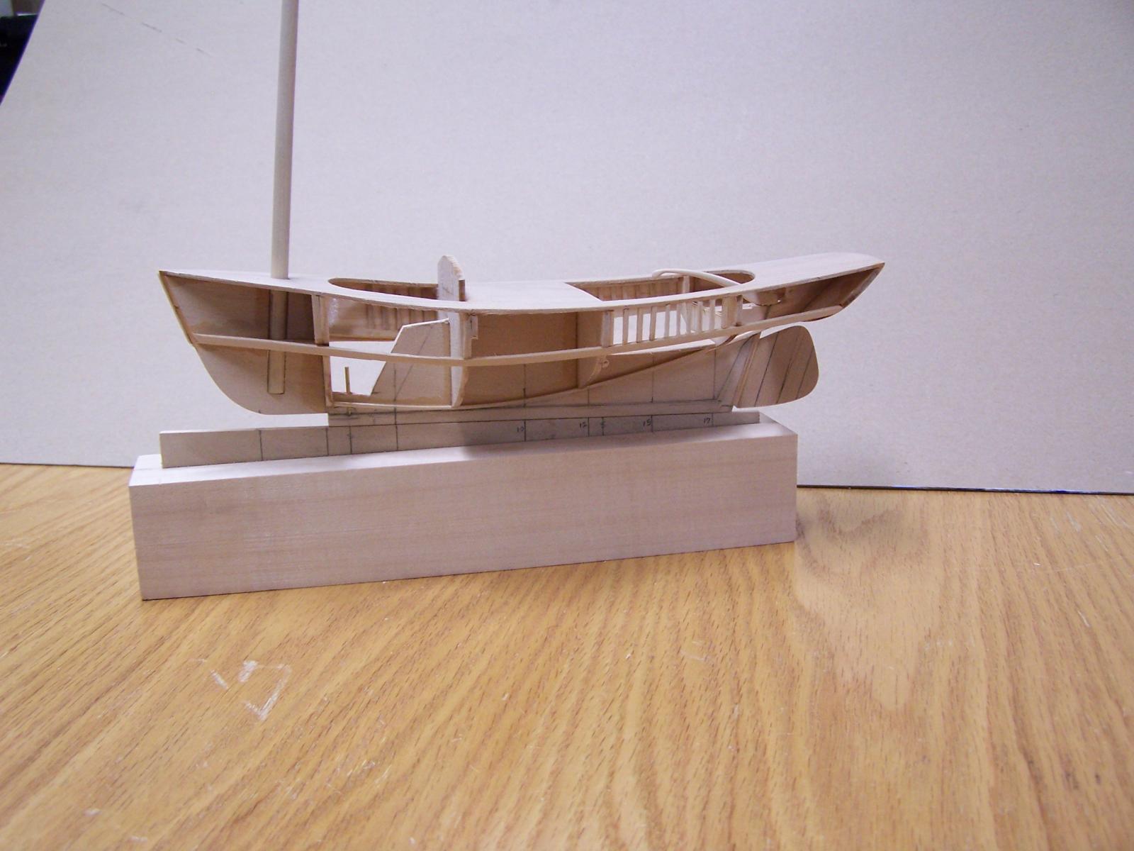
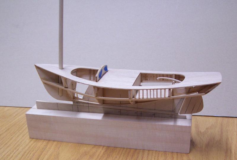
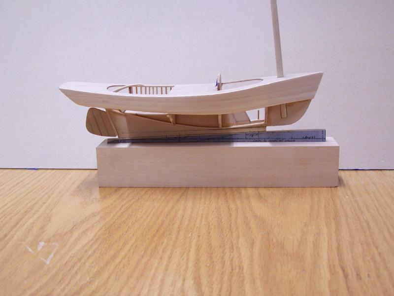
It is with some trepidation that I start a build log, after seeing the other builds on this site. Where I've seen logs that instruct, document and amaze, I have to admit I'm doing this primarily as a venue for asking stupid questions of the esteemed members...I've been lurking for a couple of months, trying to sponge up a nautical "crash course" on making little wood boats, but I'm still staring up at the distant peaks of the learning curve... Like many newbies, I saw the Midwest kit, (on sale at MicroMark) last November and said, "hmmm, wood boat model. sure, why not...?" It's a very user friendly little kit, I finished basic construction of the deck and bulkeads in a few hours. Unfortunately, I realized I knew basically nothing about these little boats, and started dabbling my toes into the deadly black hole of research... Mrs. Admiral Claus was kind enough to get me Chappelle's American Small Sailing Craft for Christmas, and it solved some questions, but raised others. I used the plans to fake in a few details, such as the fake scantlings and cutting away part of the spine around the centerboard box, just so that it wouldn't be so sparse in the open cockpit and open companionway hatch. I'm interested in making this as an actual workboat circa 1890-1900 or so, detailed imagery seems sparse, as one of sources I read stated that they had relatively short lives in the water. They stated that the use of iron fasteners caused these boats, as they delightfully put it; "to succumb to nail-sickness" after a few years. Here are the first couple of pictures showing initial progress, still mostly box-stock, but with a working rudder/tiller and some faked-in partial frames. (Also observable are some rather dismal construction techniques, featuring "firehose" CA glue application and other atrocities. Yes, it will be painted, hopefully burying the worst of it...) Regards, Bob Marvin

- 86 replies
-
- 5
-
-
- muscongus bay lobster smack
- Midwest Products
- (and 1 more)