hexnut
-
Posts
406 -
Joined
-
Last visited
Content Type
Profiles
Forums
Gallery
Events
Everything posted by hexnut
-
I've never seen this kit before, it looks like it will be a great little craft! As far as paint goes, I personally haven't had much luck w/ Rust-oleum products for small detail work, they tend to be engineered for maximum quick coverage for large areas, and go on very thick for small parts. (A test piece may prove me wrong, however, I haven't used it in a while.) I'm not sure what type of plastic the blocks are, but Tamiya makes a spray paint for polycarbonate RC bodies that's got a nice combo of durability and relatively fine application. They have a fairly limited range of colors, but they do have a flat topcoat. Of course good prep (thorough washing to rid parts of mold release, light "scuff" sanding) is one of the keys to paint durability...
-
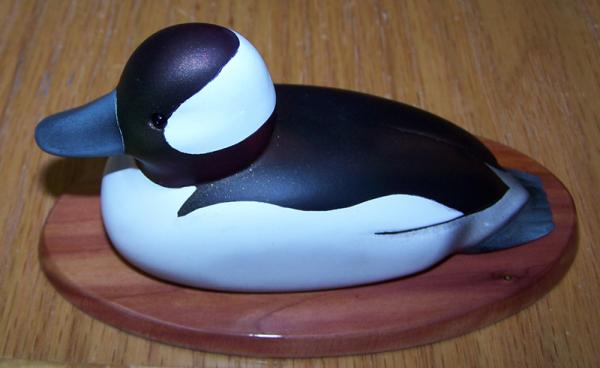
On a mini decoy(about 4" L) I made this past summer from basswood, I used Tamiya gray & white primer and semi-gloss black, overlaid with Createx Auto-air colors for the iridescence, Tamiya acrylic white/nato black mixes, gave it a day to out-gas, hit it all with Tamiya flat clear. It seemed to work fine, the primer covered like a dream. (couple of coats of gray, couple of white) I did do it as a gift, so I haven't seen it in a while--I have no idea if it will degrade over time, but usually I can tell if paint is going to go south, and it seemed solid... Good Luck!
-
Nice work! This may be your first ship,but the model aviation and railroad skills really show.
-
Thank you guys, for the support and the help. The more I try to detail this thing, the more obvious it is how little I know. Michael, if I had 1/10 the skill that you have with wood and metal, I wouldn't need 3-d cad.
- 86 replies
-
- 1
-

-
- muscongus bay lobster smack
- Midwest Products
- (and 1 more)
-
Alan, when you do "get it", please let me know, because I sure have a lot left to learn! The only way I ever learn any of this stuff is by doing it wrong a bunch of times. Even giving advice is a bit tough, as something that worked fine a bunch of times might not work for a given application. I do surfacing all of the time for work, and I still face: "it worked fine until I tried to put rads on it", "What do you mean it won't import as a solid? It told me it was a solid!" " Why won't you shell?" etc... You should be able to hit > insert> surface> loft> to get into it, pick your stations, do a simple loft, pick guide curves, etc...
-
Timo-- you made those out of the stock Midwest sail material? They look fantastic.
-
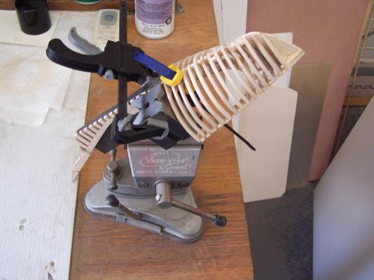
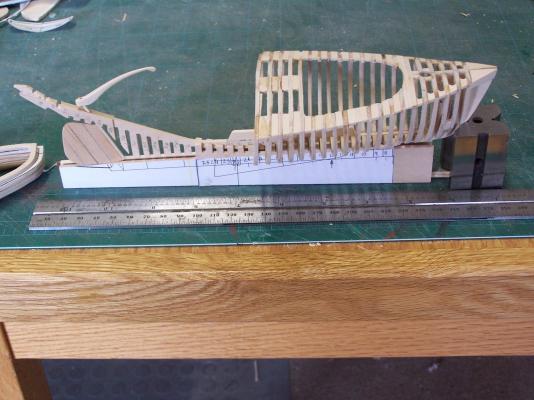
A bit more glue: false keel/deadwood clamped up: And slowly growing...
- 86 replies
-
- 3
-
-
- muscongus bay lobster smack
- Midwest Products
- (and 1 more)
-
Thank you, Cap'n! So, more like this? That would certainly make more sense for the handle length. If you would indulge me in more stupid questions: Does the angled cut in the keel bear the weight of the centerboard in the down position, or is the handle/haul/up assembly actually under tension? Thanks!
- 86 replies
-
- 2
-
-
- muscongus bay lobster smack
- Midwest Products
- (and 1 more)
-
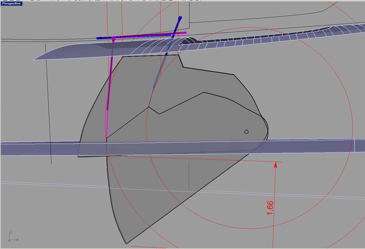
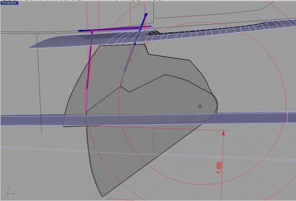
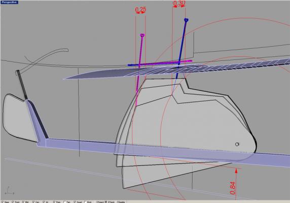
I've actually played around a bunch with the centerboard structure and one of the tentative conclusions that I've reached is that the Midwest hook may be too long. One of the issues is with the center plotted from the Chappelle plans, there is a significant horizontal component to the lift. I have modeled both the fore and aft positions for the handle, showing an intermediate link (or chain) connecting to the centerboard. Dimensions are in 1/24 scale. Edit: I've shown the centerboard at the lowermost point as shown on the Midwest plans, but it occurred to me that I don't really know if it goes deeper than that. If it does, then the length of the board hook may make a lot more sense.
- 86 replies
-
- 1
-
-
- muscongus bay lobster smack
- Midwest Products
- (and 1 more)
-
Thank you, Senior Salt, I look forward to seeing some of your great work in New London next month! re-posted some missing images.
-
Bob, on my ongoing quest for info on these boats; were the centerboards always stowed when moored?
-
Nice work! Some suggestions: 1) work only on a "half model", you can mirror it later. This will save on the number of points that it has to interpolate, reduce some variables and help a lot when you model the rounded bow. (sketch the bow waterlines full to make sure you will have tangency, then split for the half model guide curves.) 2) extend station lines to a flat top ala Hahn method. this will help the breadth lines stay fair all the way to the top. (try lofting just to the topmost of the breadth curves that you have drawn, just to see if that cleans up any.) 3) now that you have guide curves attached to the station lines, try lofting surfs w/out using the actual stations, or dropping a few. Take asection where you had a gouge or bulge before, see if it is close enough to the original section. Sometimes it will fair well and be close to the original cross-section, just using that original station to define it forced the surf to accelerate too hard to maintain tangency at that pointset. As far as hardware, I don't know how much ram you have in it, but with single-threaded ops like 3-d cad, sheer clockspeed is a huge factor. The good news is there are some fast fairly cheap boxes out there now. (Not as much fun as a tablesaw, maybe, but quite useful...) also don't buy "fully loaded" ram simms from the computer mfg., buy ram direct from Kensington or Tiger and install @ home--much cheaper.
-
Yes, still amazing! Thank you for the nice and clear explanation to both Remco and I about your printed depth marks. (I am trying a similar "Trompe-l'œil" technique for another project.)
- 222 replies
-
- 1
-
-
- gorch fock
- barque
- (and 2 more)
-
Consistently amazing. I love how you harmonized the printed depth mark numbers with the steel hull plates. Are the rivets on the printed pieces printed as well, or are they dimensional? (applied separately to photo paper)
- 222 replies
-
- 1
-
-
- gorch fock
- barque
- (and 2 more)
-
Looks great! Gotta love those Technics gears. I use them once in a while for breadboards at work-- What costs $200 @ Stock Drive Products costs $40 @ the toy store.
- 85 replies
-
- 2
-
-
- yacht mary
- mamoli
- (and 1 more)
-
I've read that the sail area was so that they could get away from the dock and underway with almost no breeze, as these were made and used before auxiliaries. Apparently, they were almost always reefed during normal "working hours". Your model is looking terrific. I really love the paint and finishing.
-
Looks interesting. If it turns out anything like your Olympia, it will be another masterpiece!
-
34ft Danish Cutter by adamdt
hexnut replied to adamdt's topic in - Build logs for subjects built 1901 - Present Day
This looks like a great project, very nice work. If you want to save a lot of time, I might suggest a basic set of ship's curves like these: http://www.usartsupply.com/ItemDetail.aspx?ItemNo=CTH+SC-66&gclid=CMmHu4-njb0CFQ2hOgod6CoAdw Or you could go "old school" and use a long, narrow strip of wood, plot points where you need the curve and run the wood through the points, holding it down with some desk weights. I believe Michael Mott made a beautiful set of these, referred to as "ducks" (as in--"ducks in a row"), but bench blocks or small cans filled w/ fishing sinkers will do in a pinch. If you haven't done so already, getting all of your measurements into an Excel spreadsheet will also be an immense time-saver down the road, especially when doing station offsets. -
From what I've read, I could see captain Walters really enjoying that concept... Beautiful detail work!
-
I used to play with cars a fair bit (hence the avatar) plus, my company logo is hexagon-shaped. It was just something I started using on another forum years ago and I was too lazy to think of a new one...
-
Thanks, Dee_Dee. --41, but who's counting? I'm still mulling over if I want to do a single or double-post design. The prow is the only area of the boat where I have a solid bulkhead, so I'm definitely not going to bother making a "real" mounting. (maybe on the next one--these little things are sort of addictive, aren't they?)
- 86 replies
-
- 2
-
-
- muscongus bay lobster smack
- Midwest Products
- (and 1 more)
-
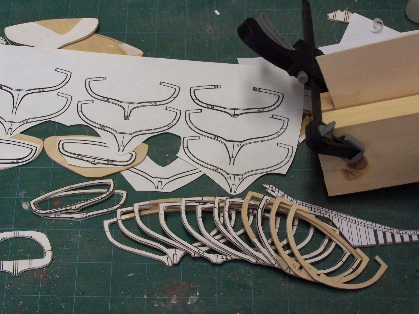
Nothing too exciting, just making frames...

- 86 replies
-
- 4
-
-
- muscongus bay lobster smack
- Midwest Products
- (and 1 more)
-
Wow. really nice work, I was just looking at some of the great models that you posted in the gallery. Do you have any plans to show any of them at the New London meeting this spring?
-
I just read through the "scantlings" topic, and all though there is a lot I don't understand (I still don't really know very much about ships yet) I do have some experience with surfacing, Don's approach makes sense to me. Even though the hull I'm working on is a lot smaller, newer, and vastly less complex, getting the stations, buttocks and wl's all attached and faired was the toughest part. --the Zebra stripe command got a good work-out, constantly checking for surface glitches. One thing that helped for my particular hull shape (I don't know if it will do any good for yours or not) was to split it amidships and drive the forward surface w/ the wl's and the aft w/ the buttock lines.