All Activity
- Past hour
-
 GrandpaPhil reacted to a post in a topic:
PHOENIX 1787 by ccoyle - Master Korabel - 1/72 - Russian brigantine of the Black Sea Fleet
GrandpaPhil reacted to a post in a topic:
PHOENIX 1787 by ccoyle - Master Korabel - 1/72 - Russian brigantine of the Black Sea Fleet
-
 GrandpaPhil reacted to a post in a topic:
Oryol 1902 by GrandpaPhil - Orel - 1/200 - CARD - Russian Battleship
GrandpaPhil reacted to a post in a topic:
Oryol 1902 by GrandpaPhil - Orel - 1/200 - CARD - Russian Battleship
-
yvesvidal reacted to a post in a topic:
Steam Schooner Wapama 1915 by Paul Le Wol - Scale 1/72 = From Plans Drawn By Don Birkholtz Sr.
-
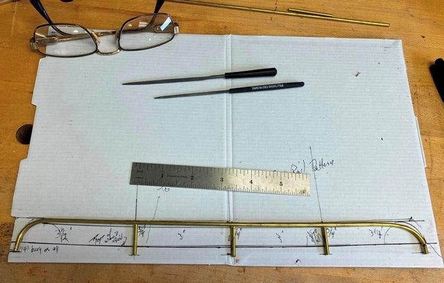
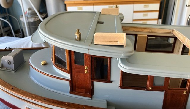
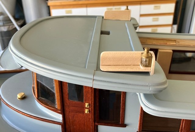
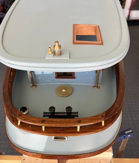
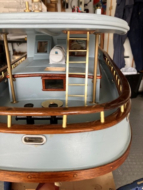
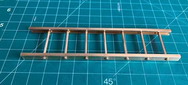
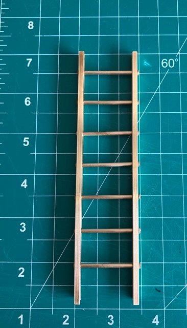
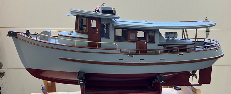
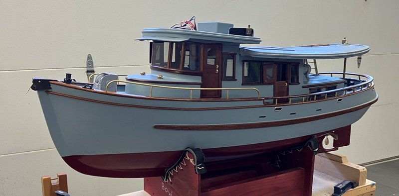
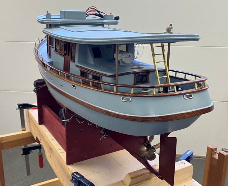
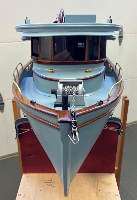
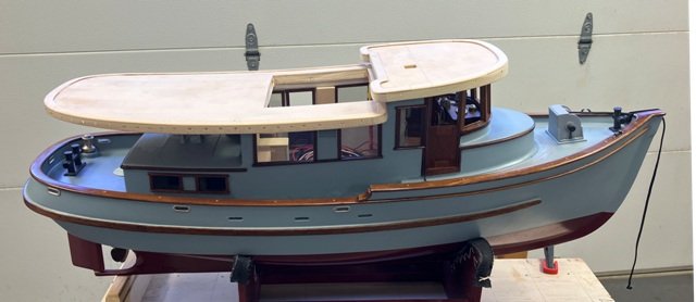
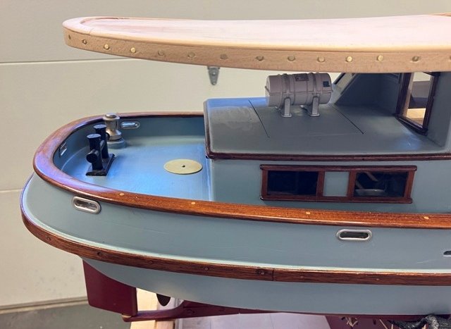
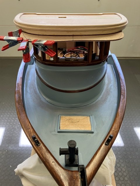
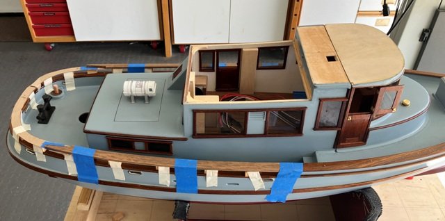
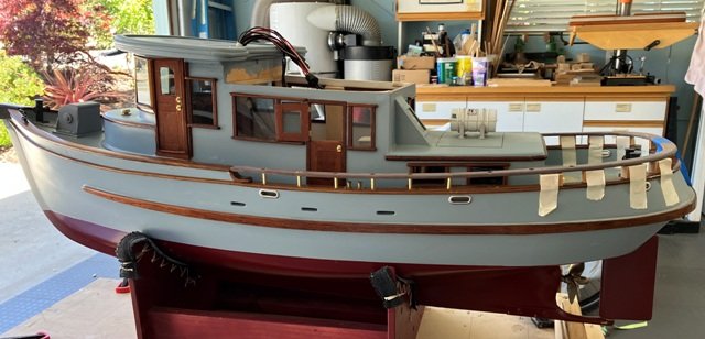
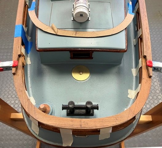
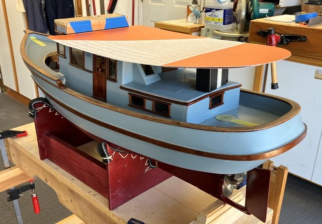
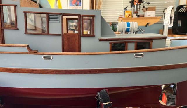
 Okay - Final segment to bring the log current is as follows: Brass foredeck handrails were soldered together from rod stock, laid over a developed pattern for alignment. I cobbled up a wooden bending jig in an effort to keep the bends smooth and the upright posts were coved to fit tightly to the underside of the long rails. The lower ends of the supporting posts were fitted into holes drilled in the forward caprail. These handrails were deliberately made stouter than scale might require in anticipation of possible rough handling when launching or retrieving TWILIGHT from the water on her working days. And, as you will notice, somewhen about this point, the cabin tops got painted. The aft overhang of the main cabin roof was intended to be supported on a pair of main deck-mounted upright posts, which were also braced to the aft face of the after cabin. The assembly of these posts took a couple of tries to get the fussy soldering to cooperate, but with guidance from Ken Forem's book, the task was ultimately accomplished. The port and starboard running light mounts were glued up from basswood (and the outboard faces painted black). The light fixtures are outfitted with the appropriate colored LED's and the assemblies were then affixed onto the permanently mounted after portion of the pilothouse, with wires fed down and inboard in small holes into the upper corners of the house. While the forward removable portion of the pilothouse was lifted away, a mahogany and AYC vertical "trunk" was fashioned (in the location where the originally planned dry exhaust stack for the Gardiner diesel would have risen through the main cabin. The trunk permits necessary wires for the various R/C switches to be led to the pilothouse roof for convenient shoreside access. Before securing the main cabin roof to the house, the necessary preliminary (hopefully unobtrusive) wiring runs for the stern light and some interior lights needed to be developed. Additionally, a change in location of the ladder access to the cabin and pilothouse roofs was made from that drawn on the original drawings. The ladder was moved from a position partially obstructing the helm's view to a location at the aft end of the boat. A rectangular access hole was cut through the main house roof with my usual method and then faced with mahogany trim. Also visible are: the stern light and flag pole socket, the black-capped top of the (hydraulic) warping capstan and a stout double "H" bitt for the occasional towing opportunities/requirements which might well arise. The access ladder has been fabricated ( for the fun of it) from hollow rectangular brass stock, 3/32" dia. tube rungs and closely fitting brass brads. It does still need a pair of handrails for safety before installation. The final 4 photos of this segment will bring us current with TWILIGHT's build to date (7/7/25). A fair amount of work remains to be done above the roofs as well as with the finalizing of the topside R/C mountings. I am also hoping to to build the main cabin joinery as removable modules later this year. Until again, my heartfelt thanks to all of you for following along with the progress of this build. Your comments and suggestions are appreciated and always welcome. Craig
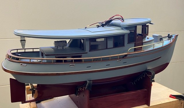
-
yvesvidal reacted to a post in a topic:
Chaperon by CaptainMac - Model Shipways - 1:48
-
yvesvidal reacted to a post in a topic:
Chaperon by CaptainMac - Model Shipways - 1:48
-
yvesvidal reacted to a post in a topic:
Chaperon by CaptainMac - Model Shipways - 1:48
-
yvesvidal reacted to a post in a topic:
Phantom 1868 by Greg Davis - Model Shipways - 1:48 scale - New York Pilot Boat
-
 yvesvidal reacted to a post in a topic:
Phantom 1868 by Greg Davis - Model Shipways - 1:48 scale - New York Pilot Boat
yvesvidal reacted to a post in a topic:
Phantom 1868 by Greg Davis - Model Shipways - 1:48 scale - New York Pilot Boat
-
BANYAN reacted to a post in a topic:
Herzogin Cecilie 1902 by Jim Lad - Four Masted Barque
-
yvesvidal reacted to a post in a topic:
HMS Portland 1770 by Trussben - Portland Scale Ship Co. - 1:48 - 50 gun 4th rate
-
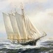 Hi Greg, Your coppering is fantastic! Your use of Tamiya tape to define the gore line really results in a clean edge. I need to remember that tip. Fortunately, my next few models will not have copper bottoms. (It least that's what my plan is now) Beautiful work!
 -
 Im In Alan, "Little Piddle" there is also a "Greater Piddle" I believe. OC.
 -
 That looks totally awesome, impressive!!!
 -
 I've managed to copper plate the rudder. Fortunately the belts line up well between hull and rudder. Time to blacken some brass and get the rudder hung.
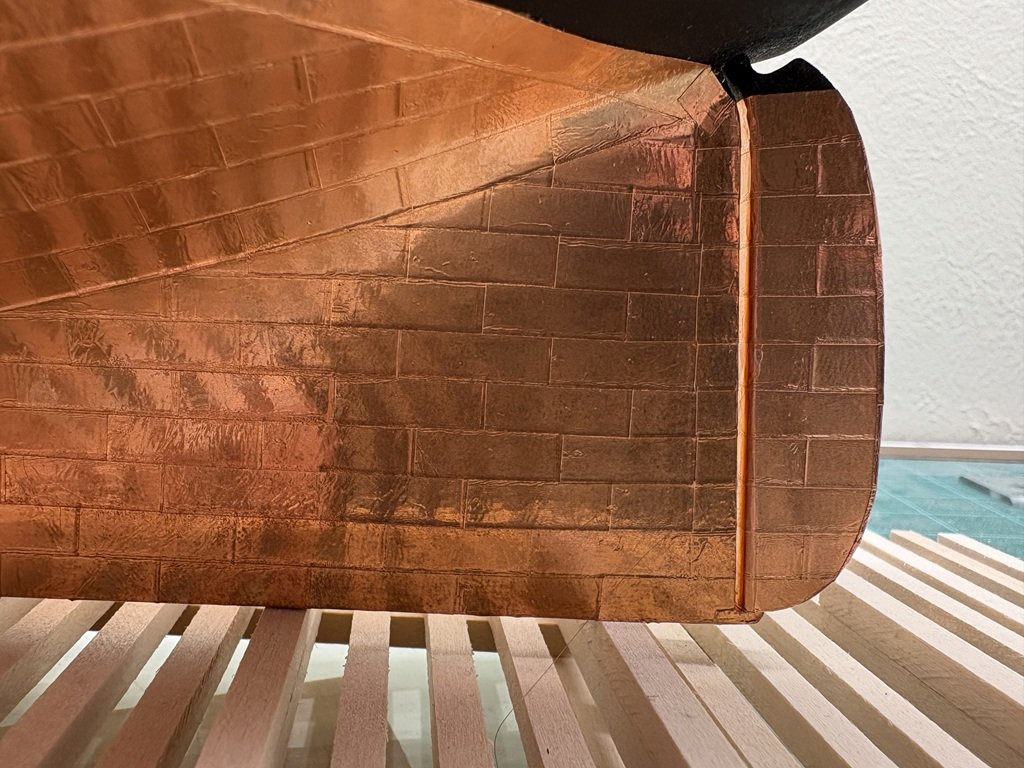
- Yesterday
-
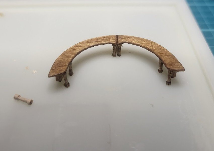
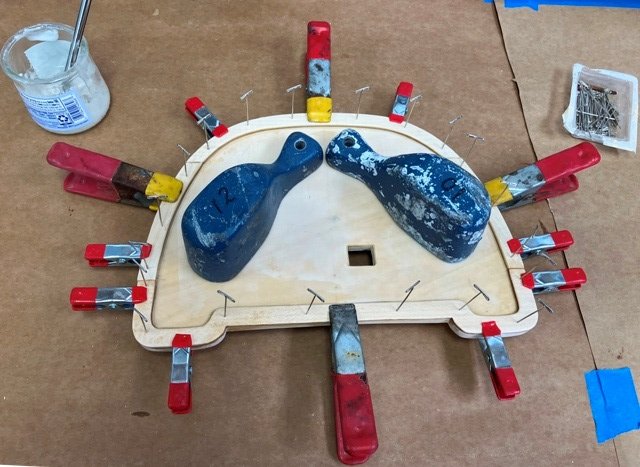
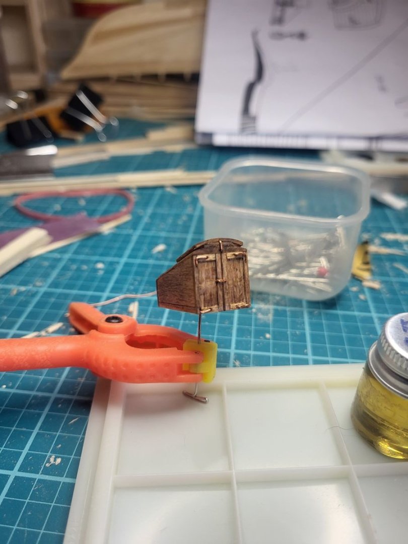
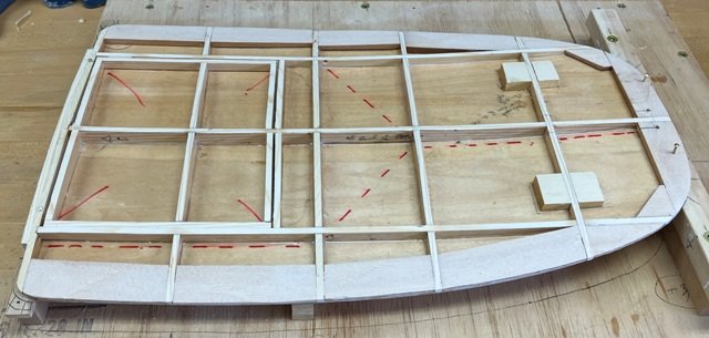
 Yet again, it's great how much data is available on this boat. Here are the seats, I turned the legs in a small Dremel. Not the correct number, but I did lose quite a few. Where do the tiny parts go when they fly off? Are they with the odd socks you lose in the laundry?
-
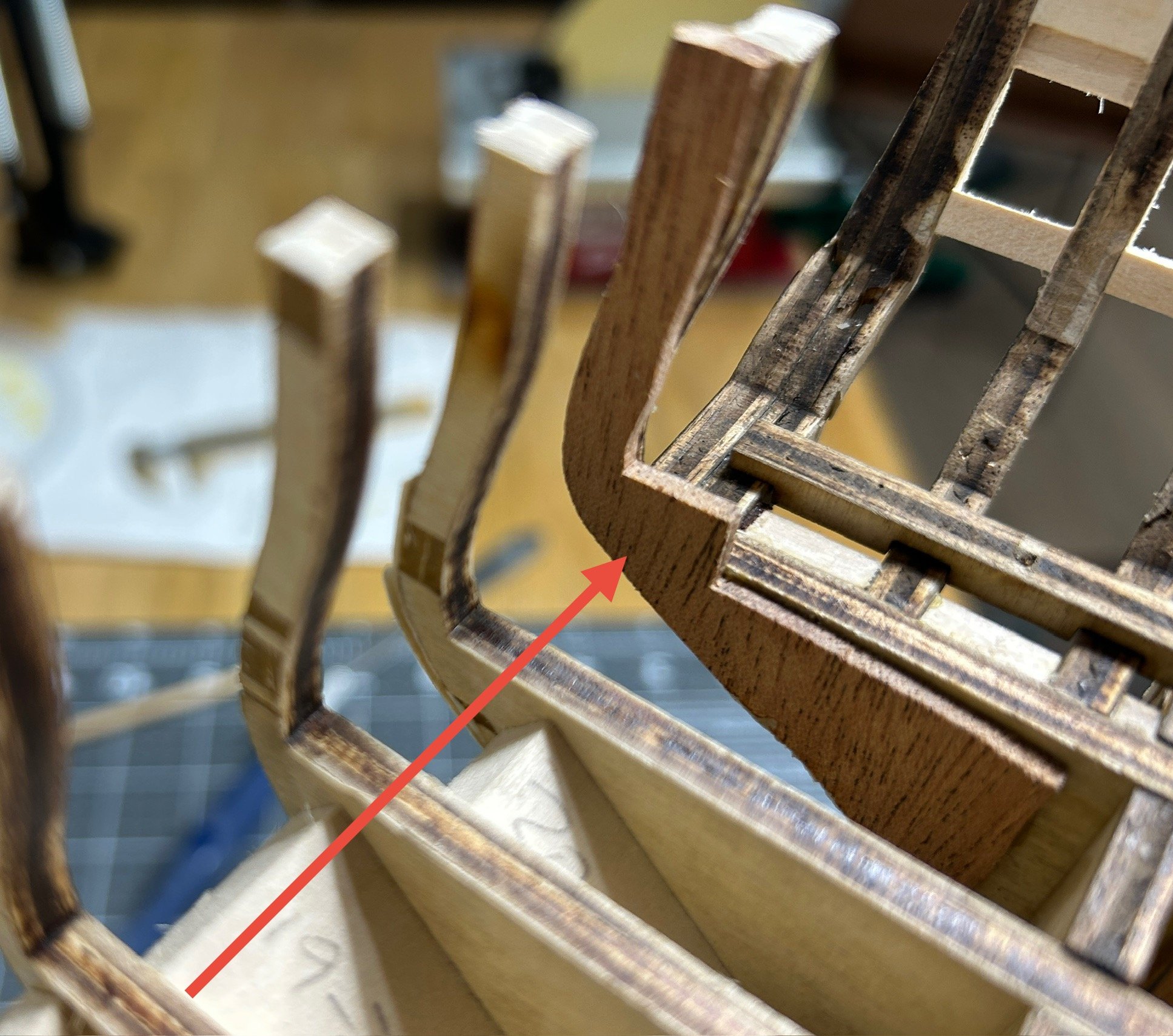
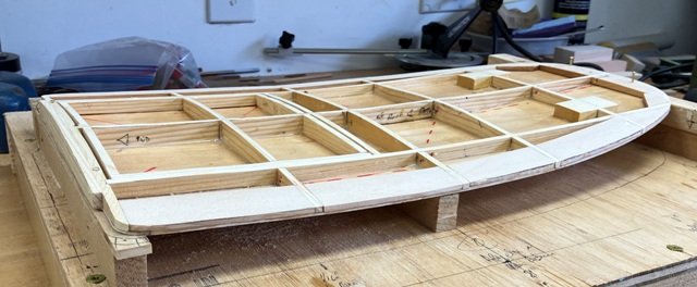
.thumb.jpeg.ffac2f8a24d212961a83eab4efb06a6c.jpeg) I have made some progress on the stern. I have managed to repair and reattach the frame pieces that broke. I also figured out that the problem I was anticipating with the arched frame for the windows on the stern. As I described in a previous post it appeared that the top of the arch would end up above the cap rail which would not be correct. It turns out that I misunderstood where the the sills were to be placed on the stern. I used alcohol to free the sills and then place them correctly. I also created some parts that will help re-enforce the bulkheads above the deck on the last bulkhead. I left some extra material at the deck level to help add some strength until the outer planking is complete. I will need to remove that material before the decking in installed. I use some 3/16 inch thick walnut. I am hoping the walnut is a little stronger than basswood. This part will also create the side of one of the gun ports. the 3/16 thickness was what I needed to have the side of the gunport in the right position. I still need to do a little more sanding and on the stern, but I have started to work on the placement of the gun port sills also. I will post an update on the sills soon.
I have made some progress on the stern. I have managed to repair and reattach the frame pieces that broke. I also figured out that the problem I was anticipating with the arched frame for the windows on the stern. As I described in a previous post it appeared that the top of the arch would end up above the cap rail which would not be correct. It turns out that I misunderstood where the the sills were to be placed on the stern. I used alcohol to free the sills and then place them correctly. I also created some parts that will help re-enforce the bulkheads above the deck on the last bulkhead. I left some extra material at the deck level to help add some strength until the outer planking is complete. I will need to remove that material before the decking in installed. I use some 3/16 inch thick walnut. I am hoping the walnut is a little stronger than basswood. This part will also create the side of one of the gun ports. the 3/16 thickness was what I needed to have the side of the gunport in the right position. I still need to do a little more sanding and on the stern, but I have started to work on the placement of the gun port sills also. I will post an update on the sills soon.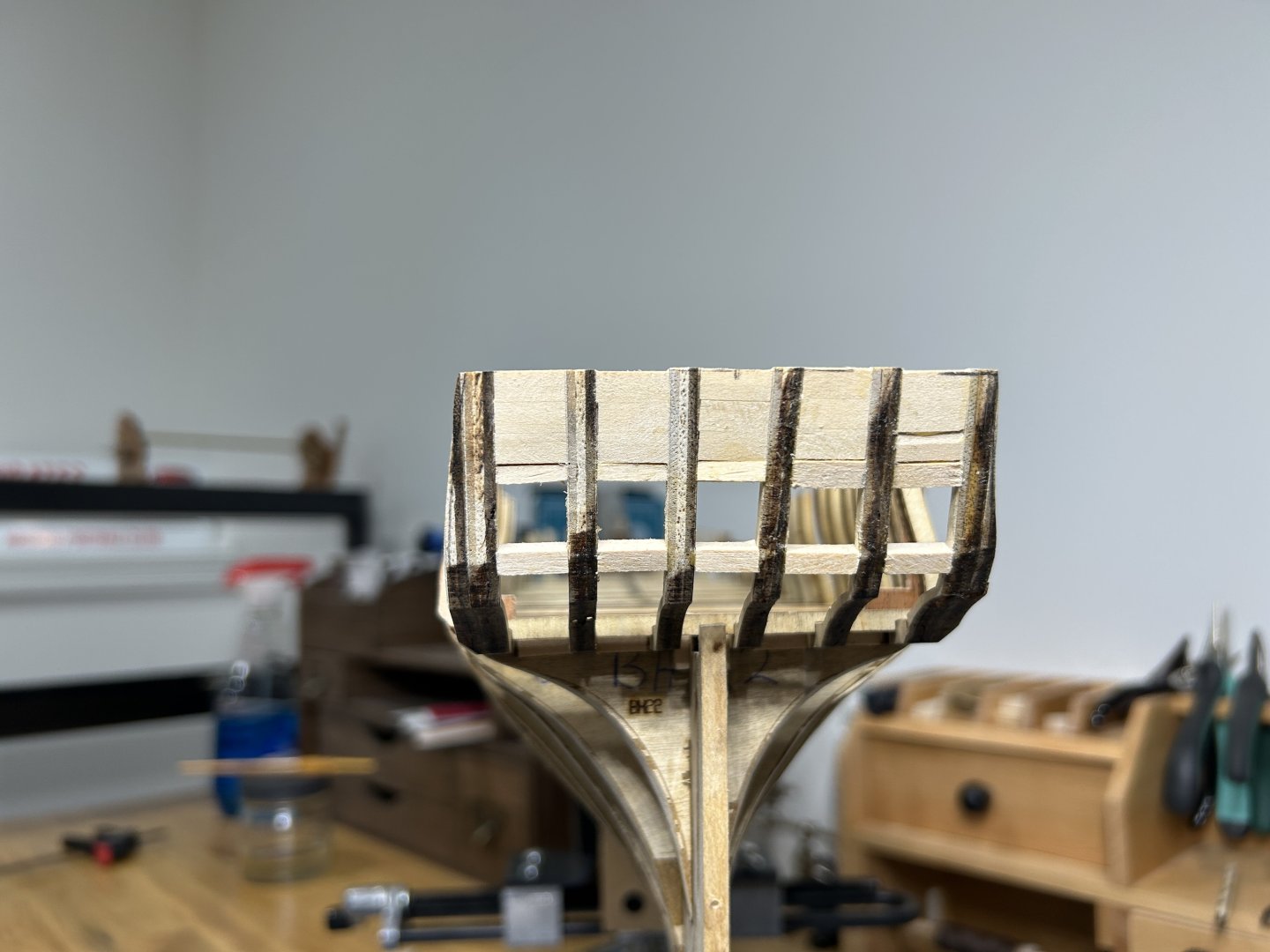

-
 Super job detailing the turrets. I still can’t believe how you do the railings. alan
- 185 replies
-
- 1
-
-
- Card
- Pre-Dreadnought
- (and 2 more)
-
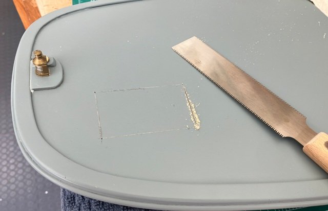
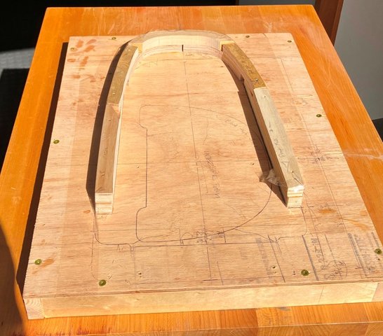
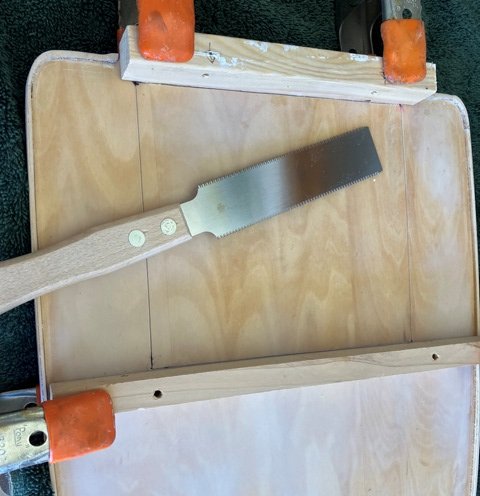
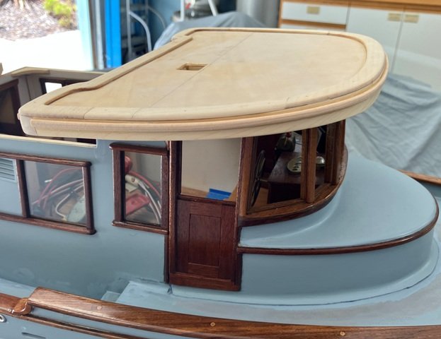
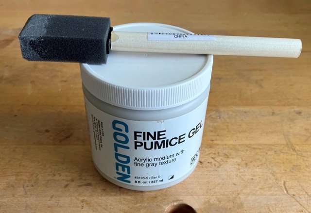
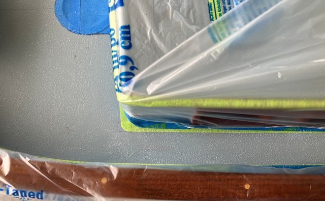
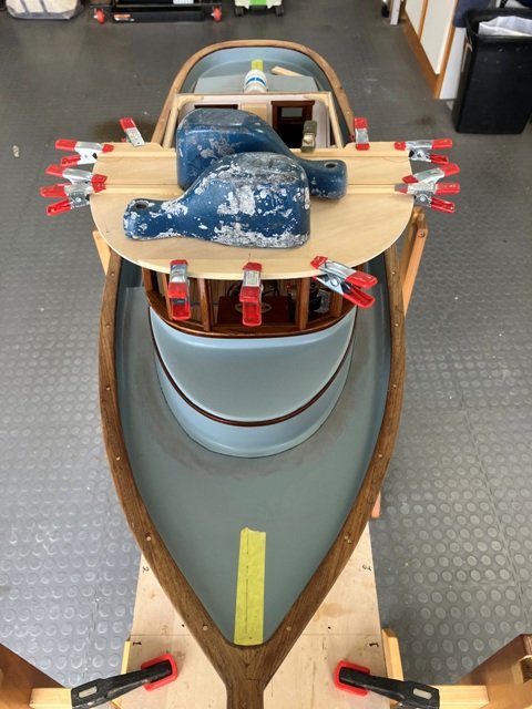
Part the next: Back to working on the roof panels. A laminating form was fashioned from scrap blocks to provide clamping positions when steaming and laminating the 1/16" thick basswood layers which formed the main cabin top fascia trim. The cured, slightly over-height fascia was glued and nailed to the outside vertical edge of the cabin top roof. After the glue hardened, the upper and lower edges were then planed to the desired profiles in elevation. Margin pieces (covering boards) were then glued to the cabin top surface, overhanging the flush roof-to-fascia seam. The outer edges of these covering boards were fair flush with the outer face of the fascia and the upper corners rounded off. The pilothouse roof was built up in a similar manner. An access hatch down through the main cabin was necessary and was cut out by first drilling #55 vertical holes at each corner, then scoring the upper and lower skins with a sharp scalpel. I used the fine teeth at the tip of a small pull saw, riding in the scored lines and braced by clamped-on guides to cut through the skins into the spaces between the interior pairs of carlins and beams. The piece of roof removed was then slightly smoothed up and given upper flanges to serve as the hatch body. The heads of the Anchorfast copper boat nails, which were used to pin the fascias to edges of the roofs, had been set flush and they were now covered by the installation of glued half-round bead trims. These trims will ultimately be painted a contrasting color. A forward-projecting "brim" was carefully shaped to attach to the lower edge of the pilothouse fascia, supported by small knees. A 1/32" x 1/32" mahogany strip was smoothed to a half-round shape and glued to upper side of the brim at its lower edge to serve as reinforcement. The extent of the deck areas which would receive a non-skid treatment could now be discerned and the finicky task of masking off the rest of the nearby surfaces followed. After experimenting with a variety of compounds, the best results (to my eyes) at this scale was developed by stippling on this pumice gel. When dried, the the non-skid was given a coat of the Tamiya (AS-26) Light Ghost Grey, which has been used for the majority of the topsides painting. The taffrail was scarfed together from suitable thickness teak stock, using card patterns to define the segments. The glued-up taffrail was mounted atop 1/8" diameter brass tube segments and secured in place with 3/4" long Anchorfast nails driven into pilot holes drilled in the main rail below. Temporary spaces blocks were taped between the two rails to help maintain the 1/2" high rail separation. The heads of the nails were slightly countersunk and later filled with colored epoxy. Once this was faired smooth, Vicky began brushing on varnish to protect the taffrail. ************* I will again pause the log at this point to keep the number of pictures in this segment reasonable. The final segment which will bring us current will be added soon. Craig
-
 Finished installing the eyebolts, cleats, and pin rails along the inner bulwarks. I'm skipping around a bit compared to the construction sequence provided in the instructions. The rudder was supposed to be the next assembly, but I have no intention of hanging that until I'm ready to mount the hull to its pedestal (which I don't have yet). Rudders just beg to be knocked loose if they're hung too early.
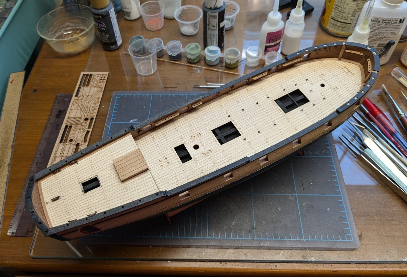
-
I never asked to be a polymath. It just sort of happened. No one really cares about things past. Unless it can be bought, sold or traded. I am re reading one of my favorite time travel stories, Jack Finney's Time and again. This is one of many variations on the Twilight zone premise of love crosses boundaries of time. Sadly this book will probably never be filmed and can never be filmed. Matheson's Somewhere in time was filmed and there were lawsuits. (But Finney is the author of the book in the Christopher Reve film. An inside joke.) See the intro to the Princess bride for the full story. Ironically Princess bride was filmed. Even though it was unfilmable. The plot does show up often and Kate & Leopold did a good job with it. Time and again can never be filmed because Somewhere in time was filmed. as was Time after Time. Not only that but the book may have caused the death of John Lennon. in the real world. (You would have to read it to find out why.) Then again this was also a favorite book of Carl Sagan, and Steven King. The idea is that if you can surround yourself with enough keys to the past you can be come part of the past. Knowledge of history is power. In Finneys version it is a government project. Huge secret warehouse. Classes etc. Much like the way Ren Faires are done. 'Drop the penny' has a negative connotation in cosplay societies. And can affect social media groups. Reading the Saginaw, (I read books in parallel) that puts one into the lives of these 19th century sailors, can get quite heady. The ownership about ideas becomes about power. Sadly a failing with how modern science works. Archeology gets embargoed. One ship I would love to model is the Antikeythera ship. I noted some of this in the above intro. I spent years studying this as a hobbiest. Eventually I met some of the researchers. Who were in town looking for some silicon valley funding. I may eventually post here walls o' text on the subject. Cousteau did dives to this. Ol Pirate Jaque found his treasure. Coins that date the wreak. Yet finding anything about this wreak is hitting an academic brick wall. A single Greek letter in an Xray scan can change whole meanings about historical scholarship. Expose lies. In this world information can be used to launder money. (like in the hidden sub plot of the recent Andor star wars spinoff.) George Lucas and his Acolytes are sneaky. I guess I left out the part in my intro where I have a two year technical degree in film making and did Apprentice work with Sprocket systems. So I saw the models up close. It does really make one question the illusions of free will. There is no creativity in hollywood. All paint by numbers kit assembly. Why I chose apple. Fakes like Piltdown man damage what history means to the common person. There are museums which have 1000s of bones, which statistically show people can be classed into well castes. Now museums are bad things. I was a big fan of the likes of Conan Doyle. Houdini, Rbt Houdine etc. (perhaps I should do a blog under shore leave on how ships influenced these guys and why I want a model of the challenger.) Doyle really believed they were going to find Atlantis. So did Cousteau. (And got the Greek government to pay for it.) So we all know what Nelson and his ships are famous for. Trafalgar Right? See who my avatar is. It is an exercise for the reader. Lord Elgin chartered those ships. (not unlike the roman senator did.) Removing the front of the Parthenon which the Greeks had blown up. Napoleon was stealing the nose of the sphinx and the Rosetta stone. NASA still suffers from the whole face on mars fiasco. So everything has to be checked and vetted. (Although the engineering data does come down in real time, but only a few can interpret it.) Pareidolia is probably why roman ships have faces. (and do cars and spacecraft.) It looks like there were problems with the shore leave section. This may be a better place to follow on with these Ideas. Why do we see faces in things like ships and such. The short of it is that when you live the past, you start seeing things that are not what they seem. Complex ideas get turned into simple memes which can mean different things to different people. Not exactly the big lie, because the big lie is a lie. I think the past is something best observed from years or decades in the future. Not so why so many people want to return to it. Not so fun when you live it. Then again, from one point of view of those Greko Roman sailors, I am a person living thousands of years in the future in a mythical land, who's myths were not even created till Some arab traders wrote them down a thousand years in my past. Not so sure why people want to return to the middle of the 20th century. The thirteenth was pretty good, I might have been happy there. I think most people do want to return to the thirteenth century. Nothing really happened then. (That is the 11 and 1200s for those who count on fingers) Yet people confuse that with the 14th. The black death only lasted four years. How much information was lost in those four years. Castles and Cathedrals were already 100s of years old then. Now forget we are 1/4 the way into the twenty first. And it was the victorians who had the catchphrase "what to do about people who wanted to live in every century but their own. " Or as my old Friend Buckaroo Banzai would say. "No matter where you go, there you are."
-
Nice rendering of the windows Al. I've seen something similar done on other model kits in photo etch. I'm chompin' at the bit to see the final reveal. Looks like she's going to be a wonderful much anticipated kit.
-
 Hi EspenT, Higher counts per strand make nicer ropes with this particular thread. Of course, it takes more time to make ropes as you are spending a lot more time walking back and forth. On a small size, such as 0.45mm, it's hard to tell the difference without magnification. I use the E121 for 0.45mm rope production. 3 threads per strand. It just looks better to me.
 -
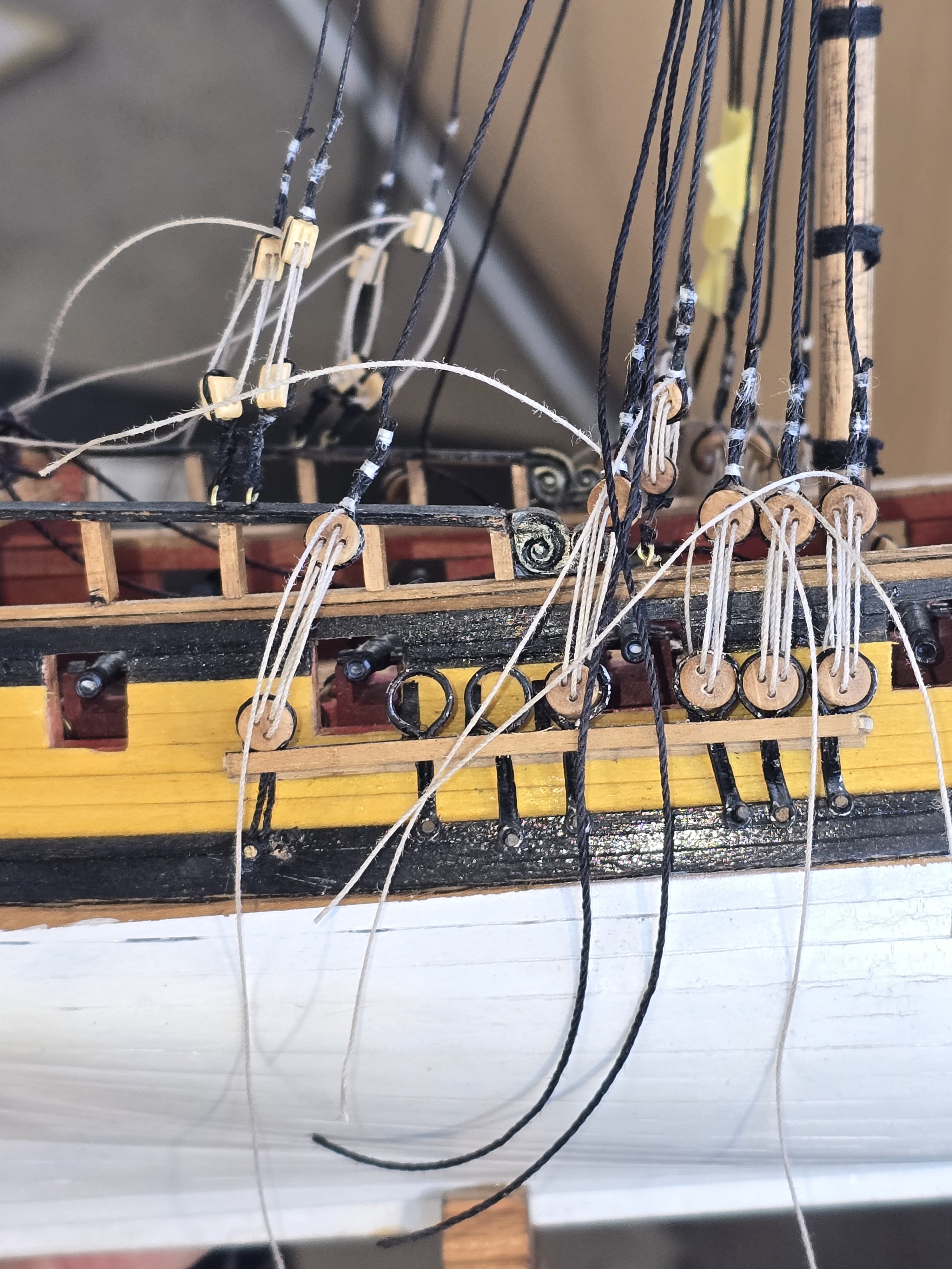
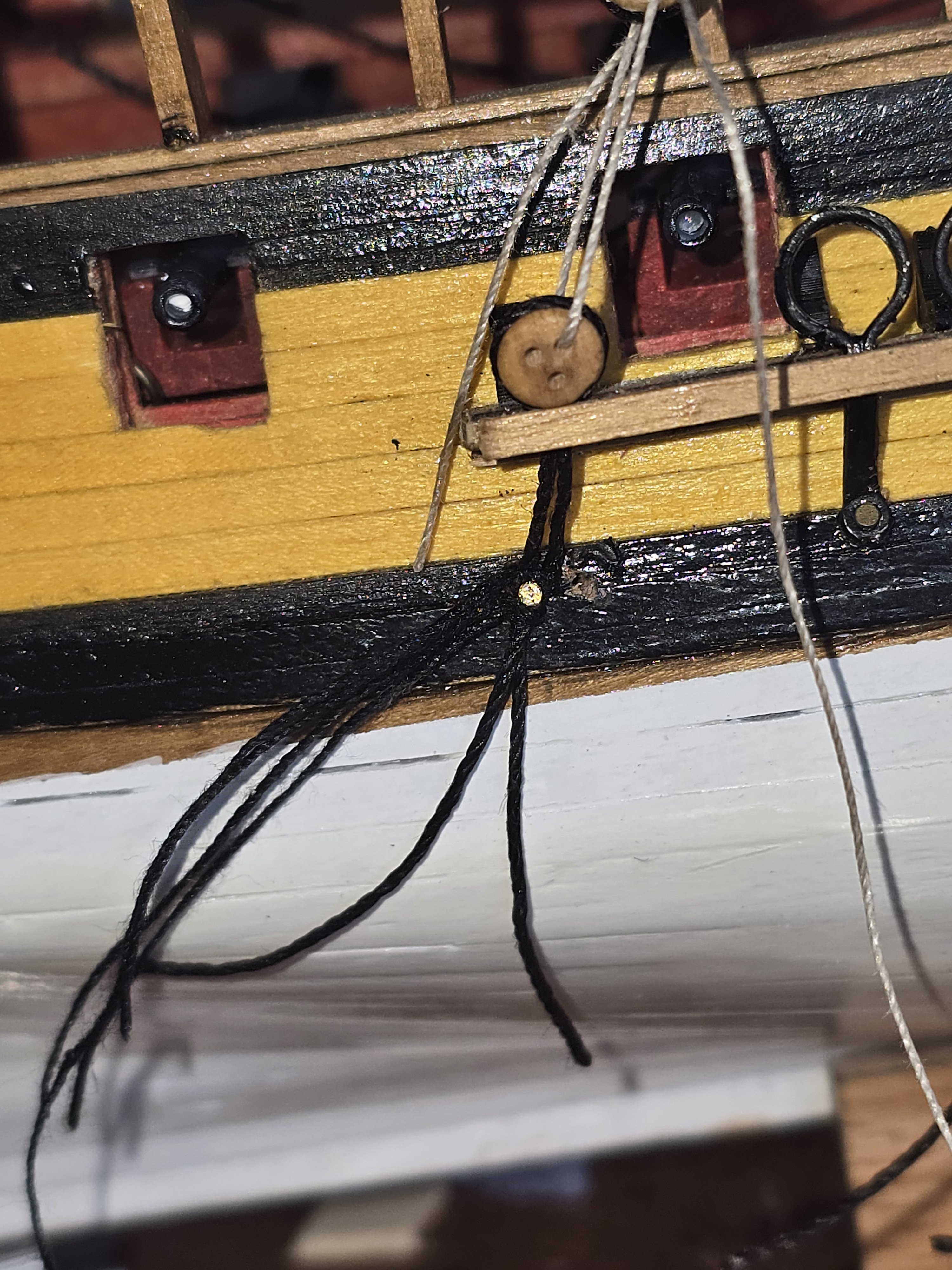
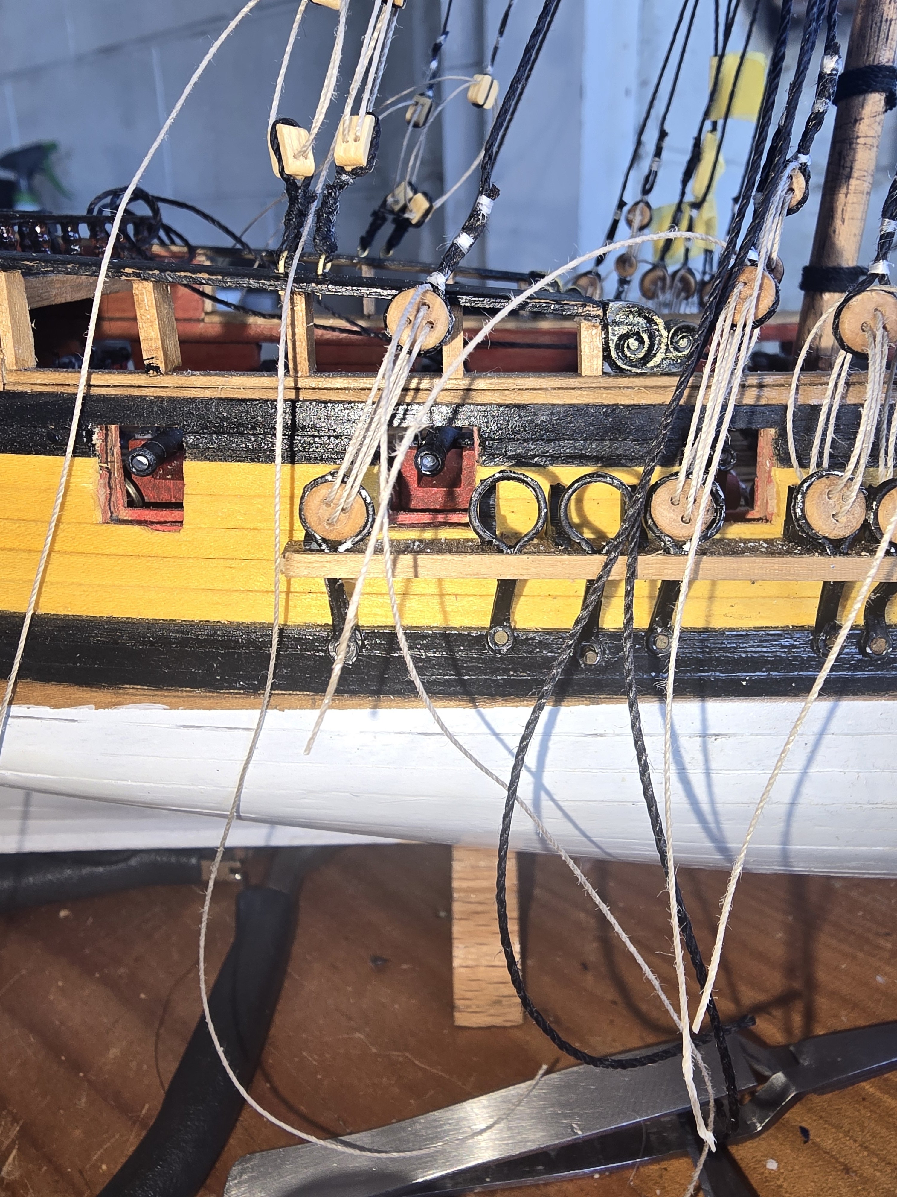
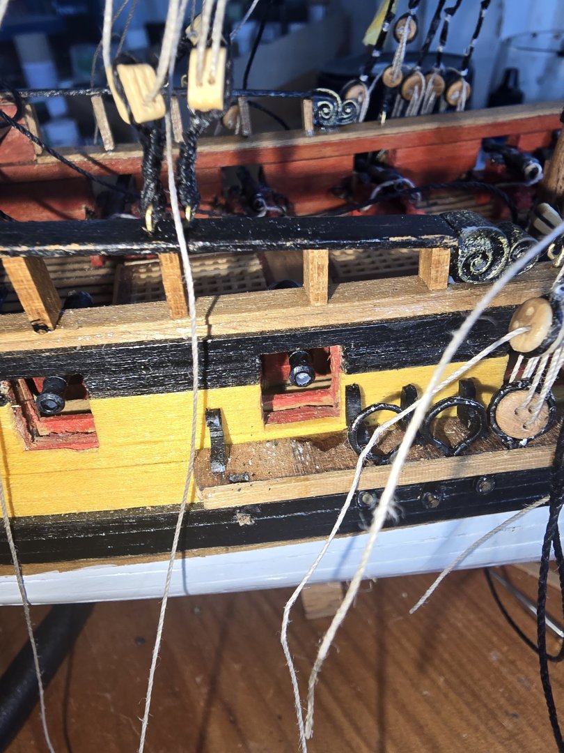
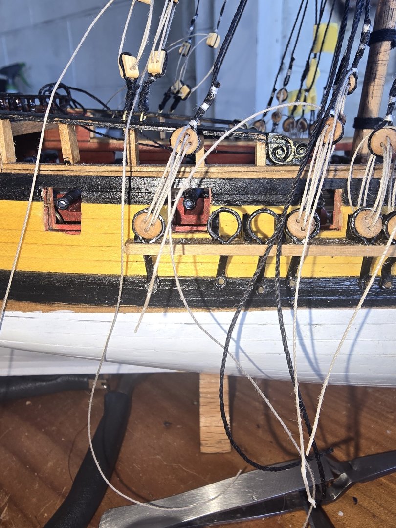
 As ive gone along with build ive realised something about building model ships. If you dont like something there isnt anything on this ship that i cant take off redo and put back on. Case in point was the kit supplied chain plates.. which are metal for a start and not in keeping with 1720 but anyway it was the angle of the chain plate with the stay and so i decided to change it this morning... 15 minutes work and its much better than it was! Dont be afraid to change things with the kit... it will be ok!

-
 Thank you for your kind comments, gentlemen. John
 -
She really looks first class, Craig. I'm glad the firefighting team was on top of things quickly. John
-
 Beautiful progress, Craig. The winch is a treat. I am so thankful the fire was both catchable and containable and that damage was limited.
 -
 Thanks George and Snug Harbor Johnny! The arch on the stern is pretty crude, but I didn’t have a better idea. No way I could carve it out of wood and no good design for a decal . Rick
- 313 replies
-
- 1
-
-
- Flying Fish
- Model Shipways
- (and 1 more)
-
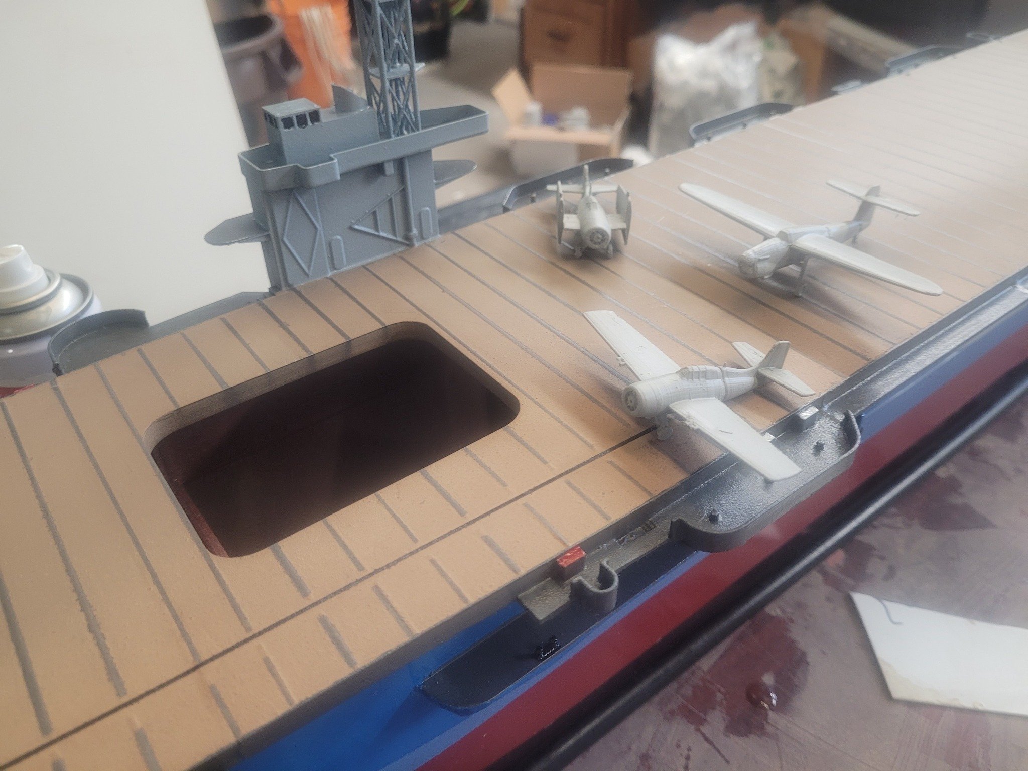
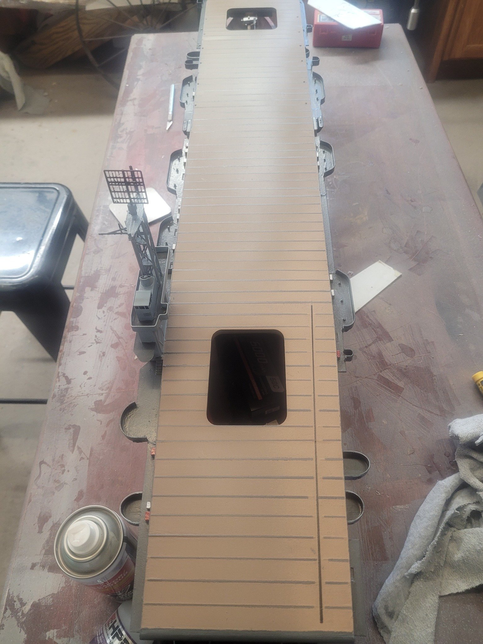
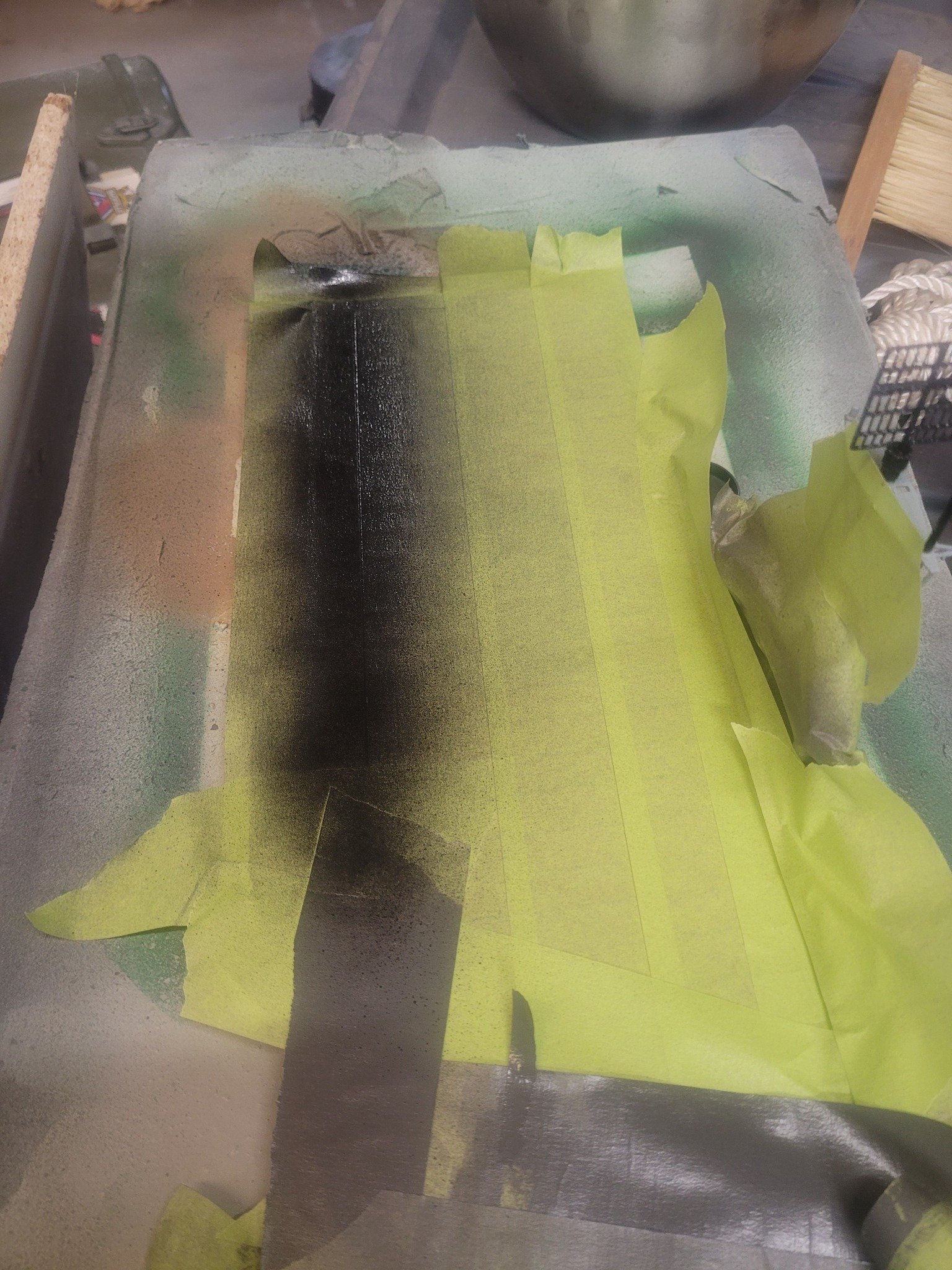
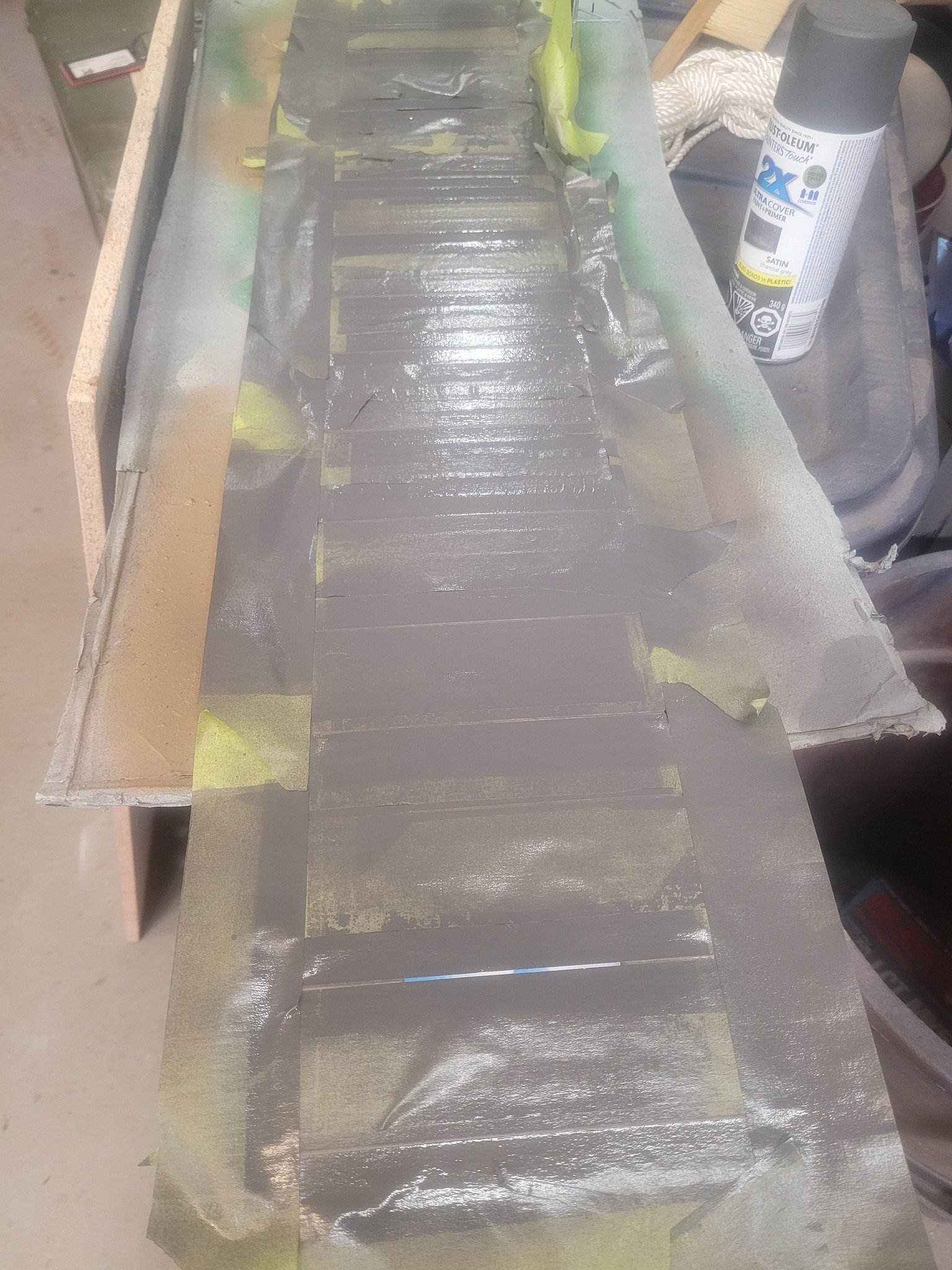
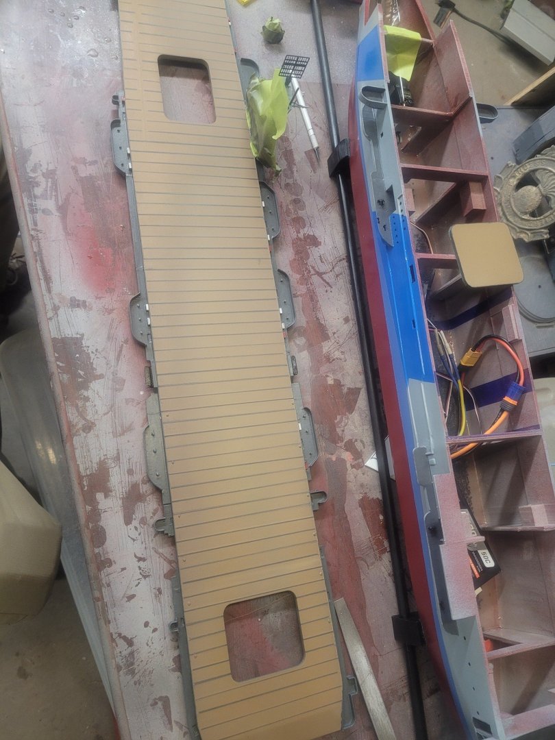
 Flight deck tie-down lines are now marked, along with the catapult!


-
After doing some research, I have remade the companionway, this is a photo I believe is from the America.
-
 dwkr01 joined the community
 -
 Proximitas joined the community
 -
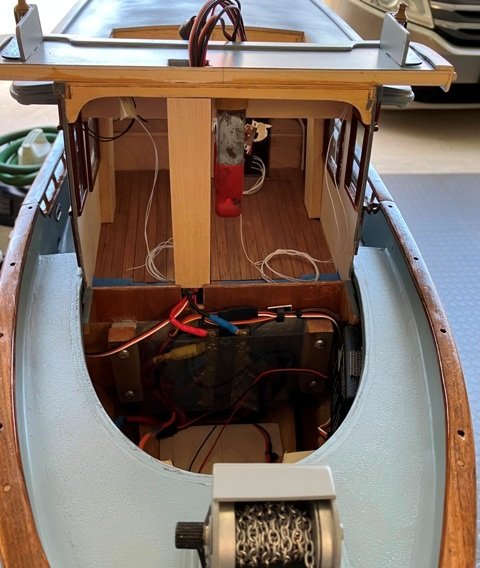
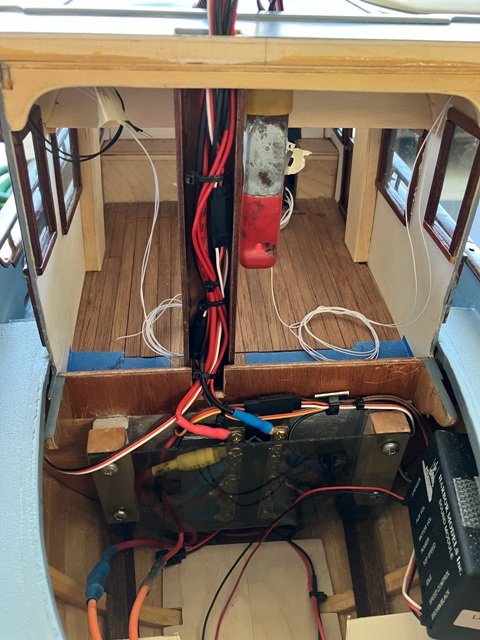
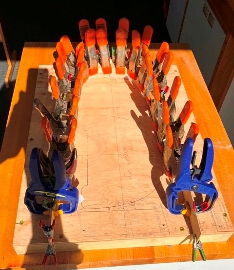
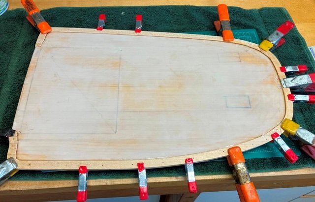
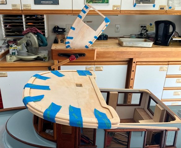
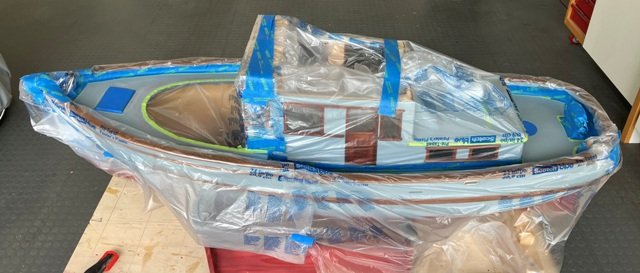
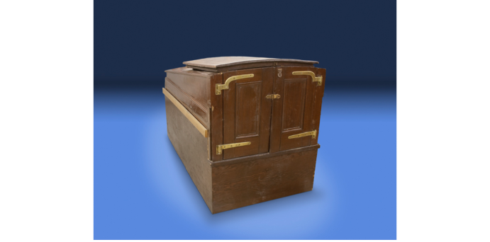
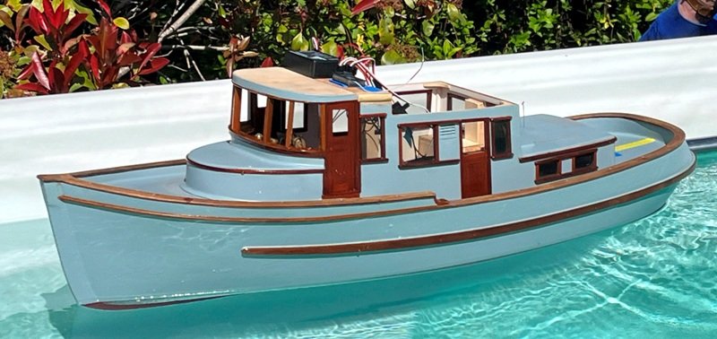
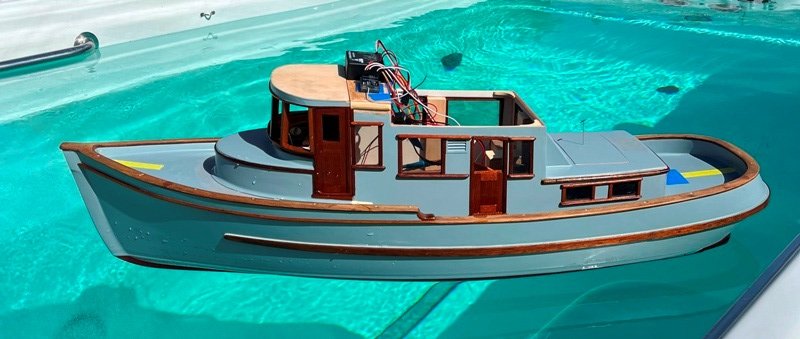
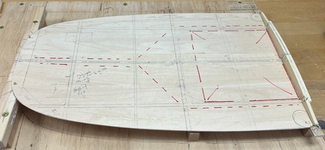
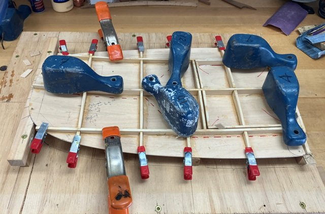
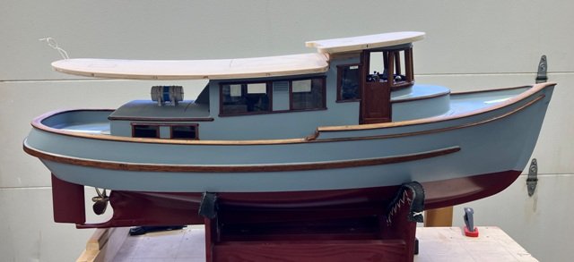
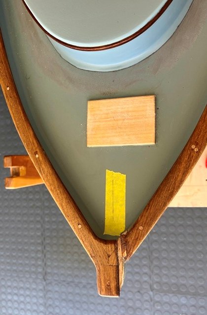
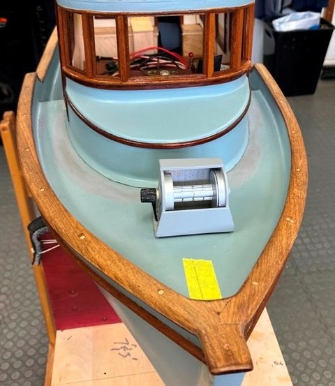
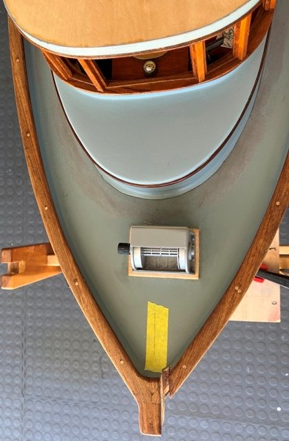
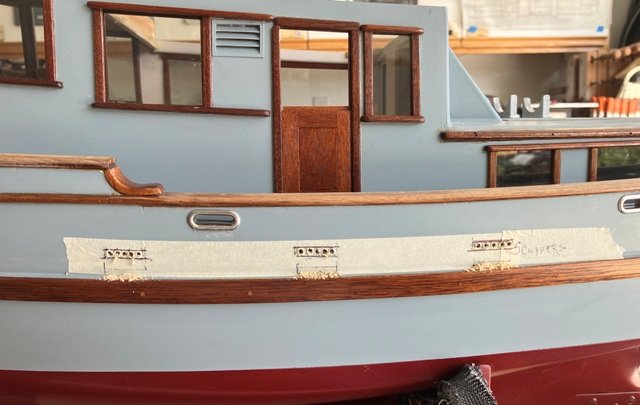
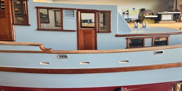
My apologies for the 3-month-long lack of posts about TWILIGHT's build. Work on the model has progressed though, so I will pick-up the tale in mid-April 2025 and, in a couple of installments, bring this wayward build log current. The pilot house lower shape was fiddled with to make a tighter fit to the deck and the electronics were (again) cobbled together to be raised above a probable splash zone. We then traipsed over to some friends' small saline pool for a preliminary "splash test". The good news was: - She floats! - She did not turn turtle!! - There was no noticeable heel. - At this stage of the build, the trim was only slightly down by the bow. - The mechanical bits worked as hoped, both in forward and reverse. - She did not take on any water. The "not-so-good"news resulted a couple of days later. TWILIGHT was back in my shop with the cabin sole hatch above the motor room removed while I tested some re-worked wiring runs. The 12 VDC feed into the ESC (electronic speed control) shorted within the potted portion of the unit and a (thankfully brief) fire resulted. While the ESC was truly "toasted", the fire was quickly extinguished when I shut off the power and none of the model's structure suffered damage. However, a goodly amount of acidic smoke permeated the interior with an acrid stench. The next couple of weeks were consumed disassembling, cleaning and reassembling everything removable as well as wiping down as many surfaces as I could get at within the model's interior. I did install a new ESC. While the fire was a setback, I am very grateful that it did not occur sometime when TWILIGHT might have been underway, out of reach - on some lake or pond! Onward, then: Once building could recommence, card template were made for the outline shapes of the pilothouse and main cabin roofs. The main cabin roof was built as a hollow, stressed skin structure (much like an aircraft wing) with 1/16" thick birch plywood for top and bottom skins and AYC for beams and framing. The roof for the pilothouse was built with similar construction, though without any compound curvature. Blocking for hardware supports and the carlins for the access hatch were fitted prior to gluing down the top skin. The upper skin had to take on a subtle compound curve and this required various clamps and weight to ensure a tight glue fit along and around the supporting structure. Once cured, both roofs were were set aside to permit work to progress at deck level. Aboard the planned full-size TWILIGHT, we had envisioned using a sturdy, commercial-grade fish-boat style hydraulic-powered, horizontal axis anchor windlass, so for the model, the location on the foredeck was given a raised basswood pad. The windlass was built up from 1/16" plywood, a re-purposed thread spool and with a spare fluted knob serving to represent the hydraulic motor. The bulwark just to port of the stem was carved out to receive a soldered brass anchor roller assembly. The bulwarks alongside of the main cabin were drilled out and the holes filed to shape in the proper locations for the hawses and scuppers. With the intent of not making any of these installments overly long, I will break this one here. More to follow shortly. Craig
-
 Hello @BenD I am testing my new rope walk with different Gutermann E-series ropes. If I want to make .45mm rope I can either use 3 strands with 3 threads each if I use E121, or I can use 3 strands with a single thread if I use the thicker E382. Do you have any preference on the quality between the different methods? I am sure you must have tested a lot of different combinations 😃. More thinner threads or few thicker threads.?
 -
 Trumpeter has good detailed and reasonably priced kits. Great Value for money. The selection of kits also is getting better every year