allanyed
-
Posts
8,117 -
Joined
-
Last visited
Content Type
Profiles
Forums
Gallery
Events
Everything posted by allanyed
-
 Daniel, Not only is your workmanship grand, the photography is exceptional as well. Allan
- 486 replies
-
- 5
-

-

-
- vanguard models
- alert
- (and 1 more)
-
Hi Dean For the plug it is catch as catch can for me. If I have poplar laying around, or pine 2X4 or bass or other soft scrap, that is what I go with. Fun times!
-
I was going to ask if this was doable and practicable so thanks for pointing this out. My Byrnes plate has seen hundreds of passes and I wondered if it and the moulding cutters you posted can be similarly sharpened? Heretofore I have made my own moulding cutters from stiff back razors or pieces of hack saw blade but for the price, these cutters look like a great alternative. Allan
-
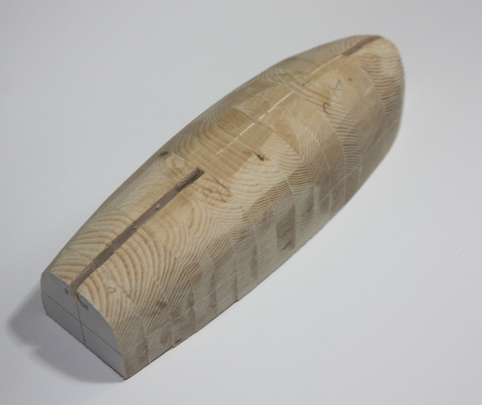
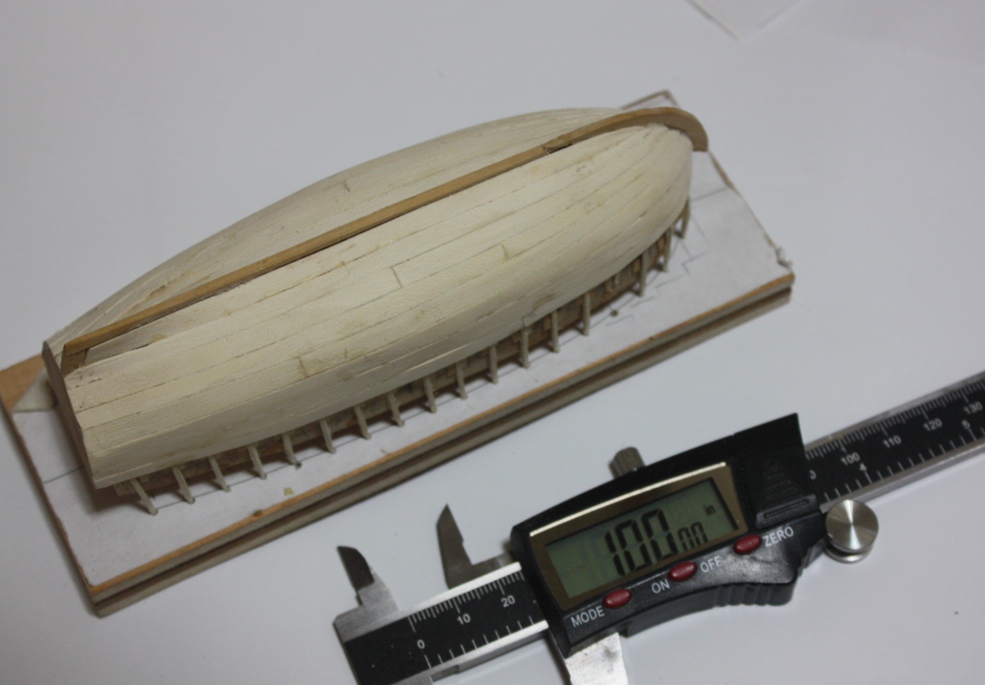
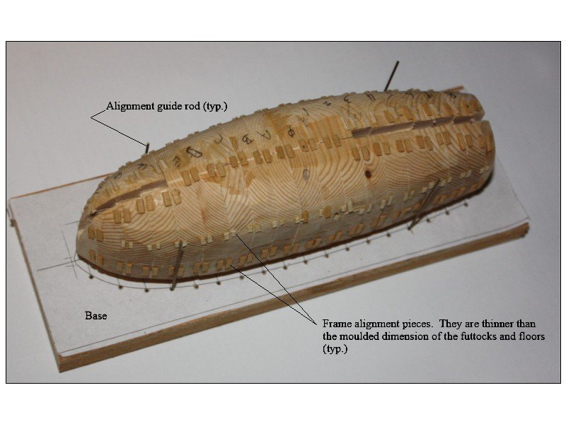
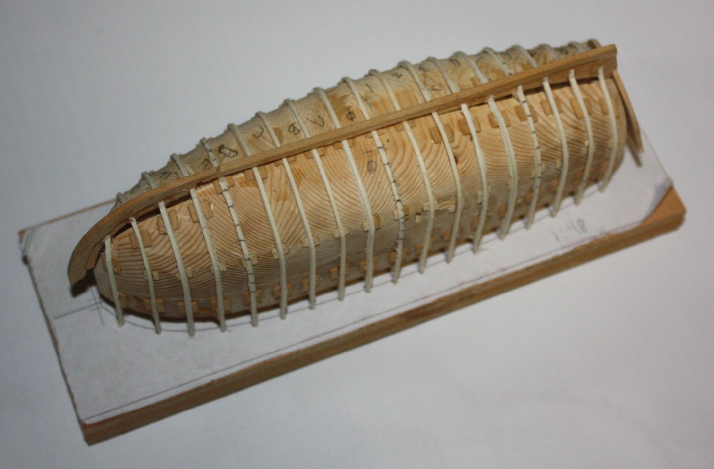
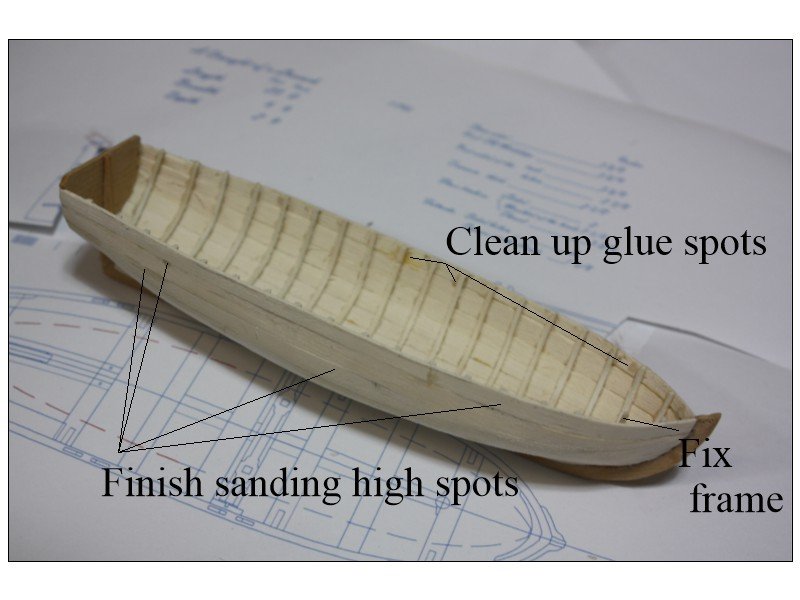
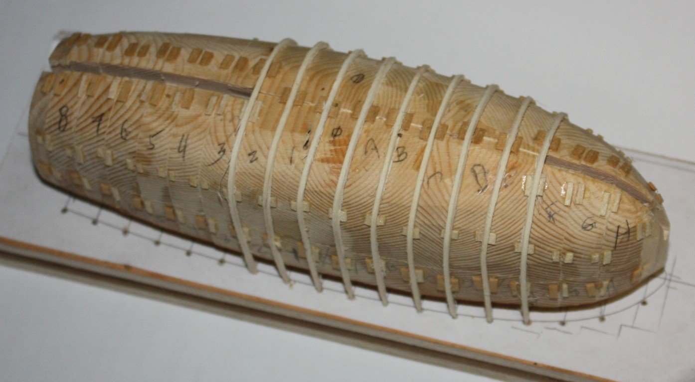
FIRST THANK YOU ALL for your quick responses. It seems I have been on the right track with the spacing as lacking other information until now, went with the station lines. Dean, This is how I have gone as well. I first saw this in Frolich's The Art of Ship Modeling and a highly regarded MSW member showed me a plug he had made (I think before there was an MSW😀) Originally I made the plug to the outside of the frames and cut grooves for the frames. Due to the high risk of a frame getting stuck when removing the hull I change to carving the plug to the inside dimension of the frames and rest the frames on top of the plug. The thickness of individual pieces of the plug are the same as the distance from station line to station line. Couple pictures follow. I think this is similar to what you describe. Thanks again to all of you Allan


- 16 replies
-
- 10
-
-
Fantastic. Very few kits address this feature resulting in a lot of bowlegged figure heads. Chuck hit a grand slam home run with this kit. Allan
-
David, Looks like it was a case of necessity being the mother of invention, Very well thought out and relatively simple. Allan
-
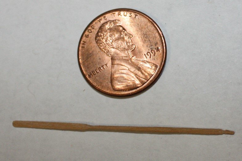
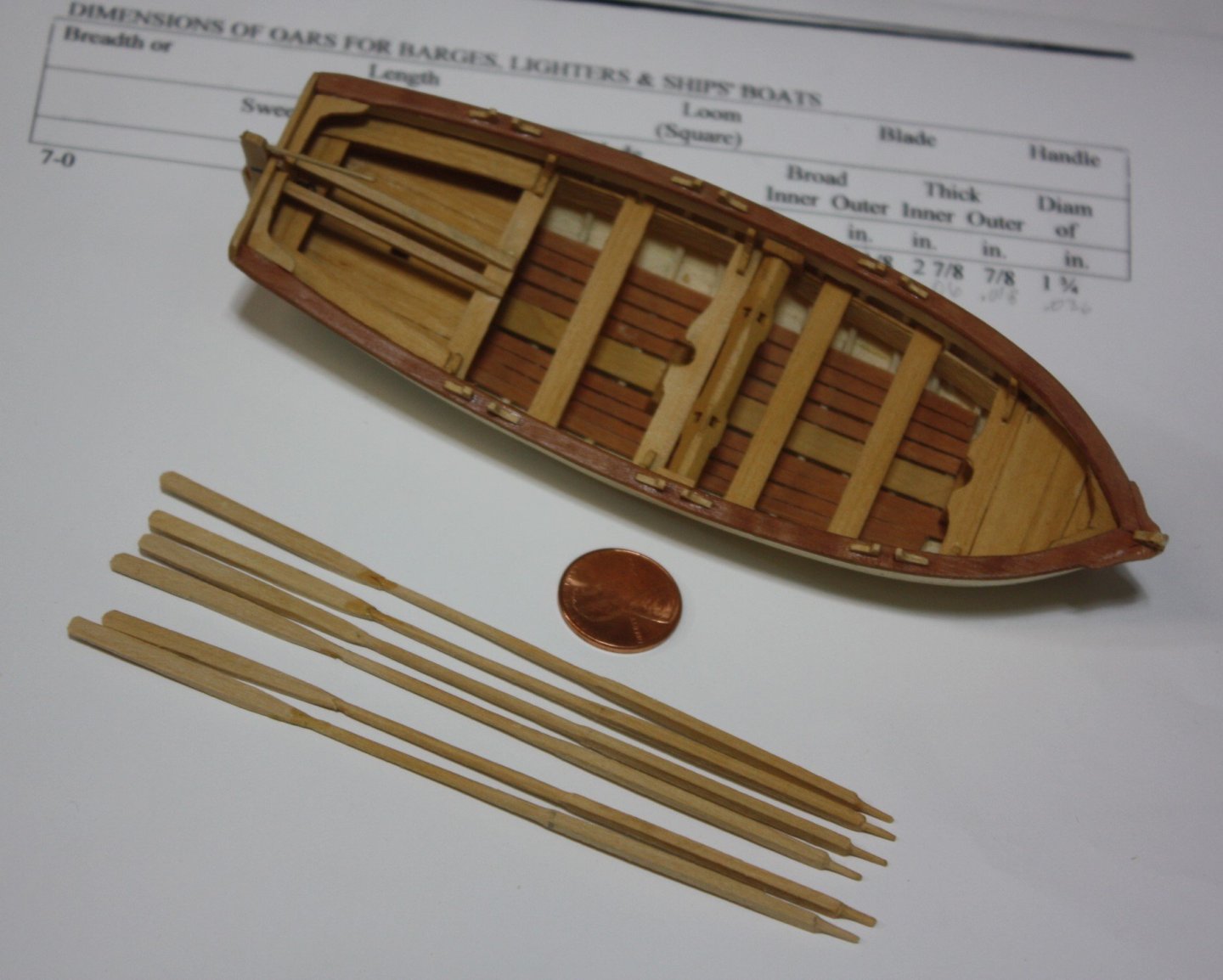
An oar at 128 scale - I saw this as a self imposed challenge and chose a 20 foot oar for a boat with a 6 foot breadth. Drawplate for part, scalpel and sandpaper for the rest. Where the shank meets the blade could use a little sanding as it is a bit heavy. The blade width and thickness are to-scale but I think it would look better if a tad wider. Overall not the greatest, but at this scale, my old eyes should be content with a little more scraping and/or sanding. Scantlings follow the photo Allan Scantlings for oars 1 to 128 scale.docx
-
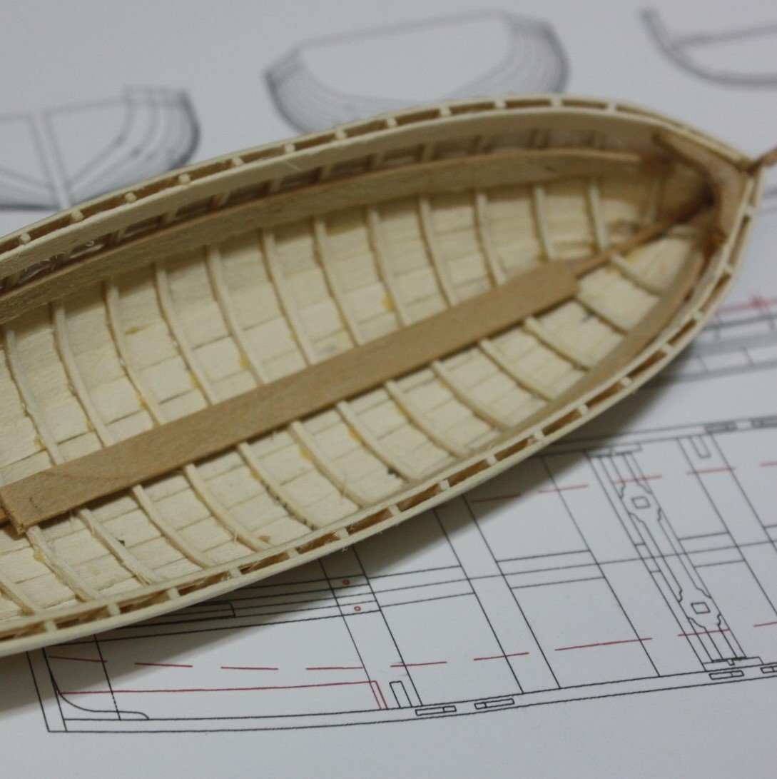
I may have missed it (or more likely forgotten) if there is a chart of the R&S for the frames on ships' boats. I have scantlings of the futtocks and floors for various types and sizes of boats from W.E. May's book on boats but I cannot find any information on the room and space. Lavery shows a drawing of a longboat of 1758 on page 214 of The Arming and Fitting of English Ships of War that describes the vertical lines as representing "frame stations" rather than just stations. These match the station lines on the body plan. I am taking that to mean there is a frame at each station, but may be wrong to make this assumption,. To now I have typically placed a frame at each station line and it works very well. If this is not correct and there is a chart or similar of the R&S that anyone can share I would be grateful. Allan
-
B.E. On the plus side, with the keelson and footwaling strakes and a full compliment of frames, much of the inside of the planking will be unseen. The planking brings up a question for which I hope you or one of your build followers can answer. Lavery makes the following comment on page 223 of The Arming and Fitting of English Ships of War: Like the yawls, it <cutters> originated at Deal, and was originally clinker built. Unlike the yawl, the cutter remained clinker built; only cutters issued for foreign service were normally carvel built. My question is, what does foreign service mean in this case? Was this for cutters on ships that sailed to foreign ports, cutters that were on harbor duty in a foreign port, or something else? Regardless, got to love the boat build and your photos and explanations. Thanks again for sharing with us. Allan
- 638 replies
-
- 2
-
-
- Indefatigable
- Vanguard Models
- (and 1 more)
-
I agree that holly is indeed limited as to where it can be used effectively, but one of the things I love to make from holly are frames for ships boats and sometimes the planking as well. If soaked for a few minutes in water, they bend like paper and hold their shape once dry. Allan

-
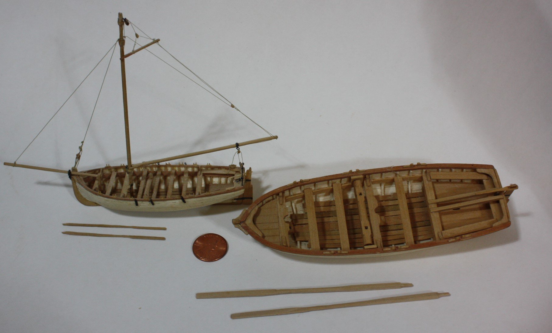
As Keith mentioned, it is sometimes better to make the oars in two pieces. The first photo below has oars in two pieces (scale1:48) The oars in the second photo are all single piece both for the 23 foot launch in 1:48 and 32 foot launch in 1:96. Hand tools were used for making the oars from scrap strips, so high tech equipment is not required. Allan

-
Just tuned in to your build and am duly impressed with the high quality of your work! I may have missed the referenced Excel spreadsheet. Is there a reference to where this can be found in posts by you, Dr. PR or elsewhere? Many thanks George Allan
-
Kudos to you for the very very nice work on the sails! I am not a fan of cloth sails as they will never be to scale at our most common scales but your sails are far and away the best ones I have seen in a long long time. Do you think a very high TC cloth (600 or more) would work as well as what you used, using your sewing methods? Again, great work! Allan
-
Just tuned in and I am very happy that I did. Love that it is a POF build and your workmanship. Allan
-
Endeavour by Bill97 - OcCre - 1/54
allanyed replied to Bill97's topic in - Kit build logs for subjects built from 1751 - 1800
You might want to study planking tutorials in the MSW data base as well as the four part video series by Chuck Passaro before tackling the second layer. Learning good planking techniques can be a big help on future projects. Allan -
Hi John, A warm welcome to MSW to you. There are alternate routes to get to your destination. Study the build logs, both kit and scratch to get an idea of what is available and what might meet your needs and desires. One of the best series, if not THE best for a beginner is the three boat series designed by member David Antscherl. https://modelexpo-online.com/Model-Shipways-Shipwright-3-Kit-Combo-Series-with-Tools-Glue-and-Paint_p_5290.html Good luck! Allan
-
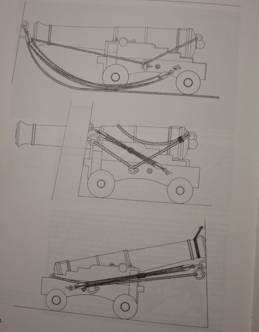
Hi Gregory These drawings from Caruana were meant as the rigging for stowed gun rigging options, not how the breech line was secured to the rings. The types of securing of the breech rope were as described in post #2. My apologies for any confusion. Allan
-
I love bamboo for treenails, but would go with another species for oars. Even then, a draw plate does not work for me for oars as they are shaped as in the pics below from Steel which I hope you find helpful. I realize the shapes were likely different from boatyard to boatyard and era to era, but I cannot find any contemporary information prior to Steel's information. Allan Oar Scantlings and oar making.doc
-
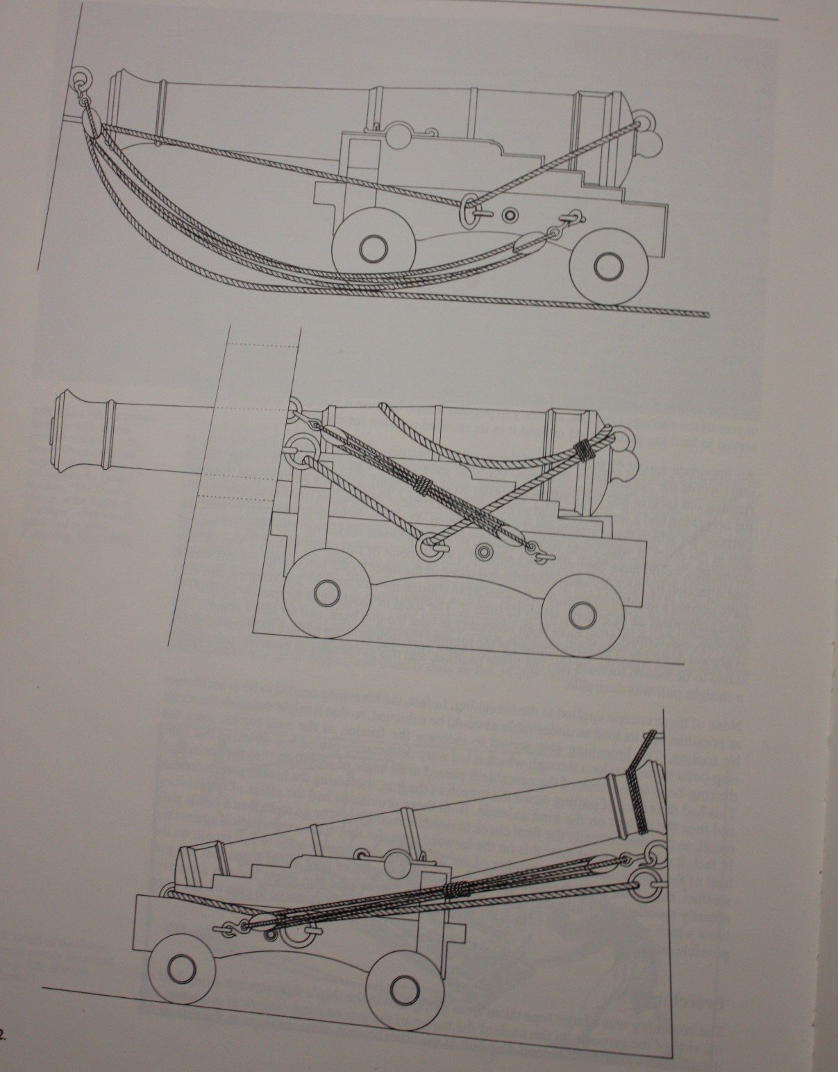
Lots of options including the three below. From The History of British Sea Ordnance Volume 2, page 382. He gives the following description of each. Illustrations of breechings and gun-tackles on a 1795 pattern carriage, redrawn from Congreve's Treatise on the Mounting of sea Service Ordnance. Top: gun tun in. Center: gun run out and secured. Bottom: gun run in, secured, and housed. Allan
-
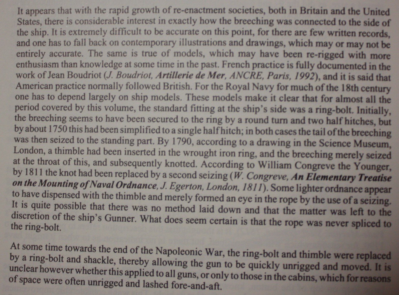
Caruana gives the following description on page 384 of The History of English Sea Ordnance Volume 2. Allan
-
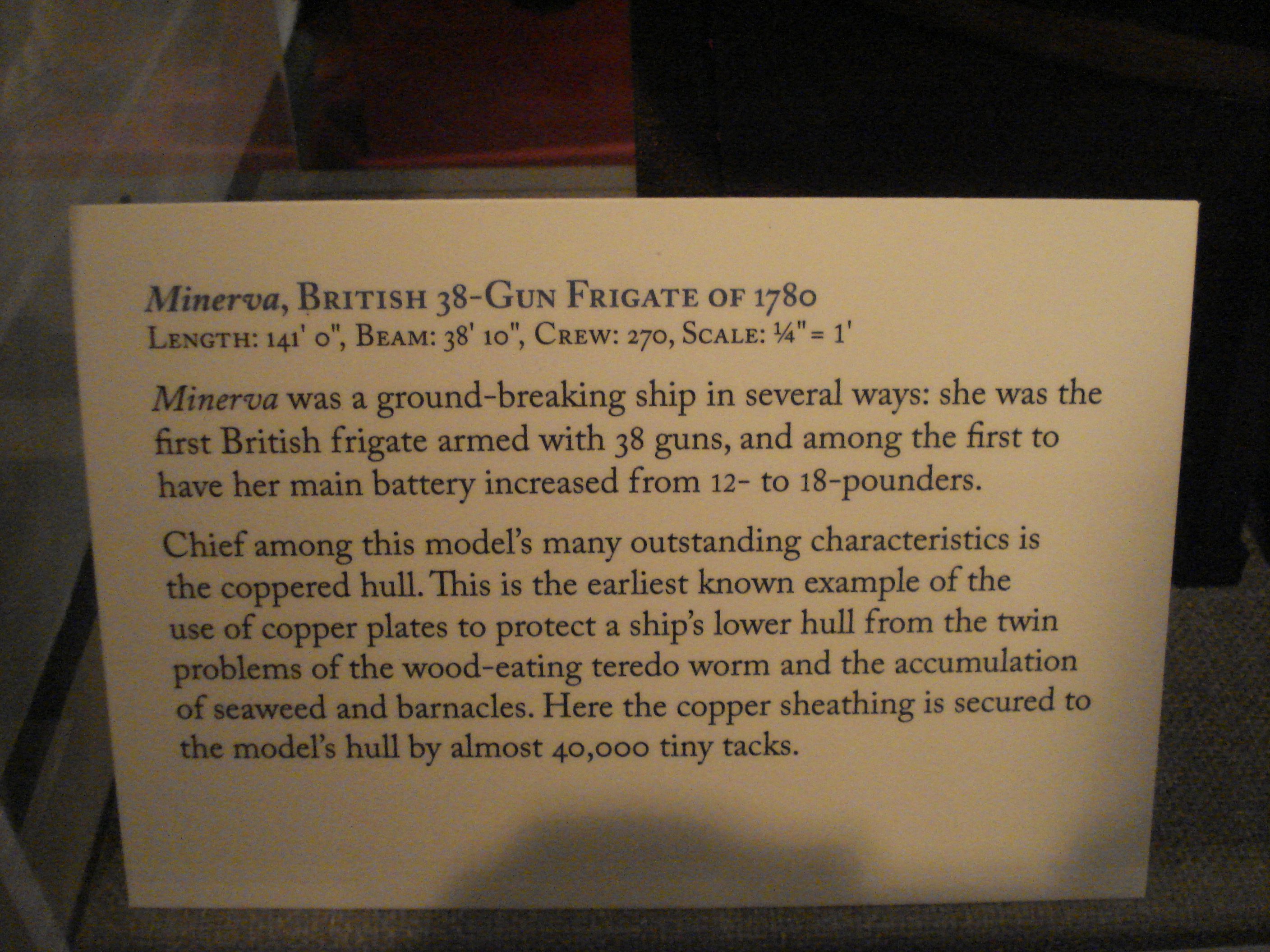
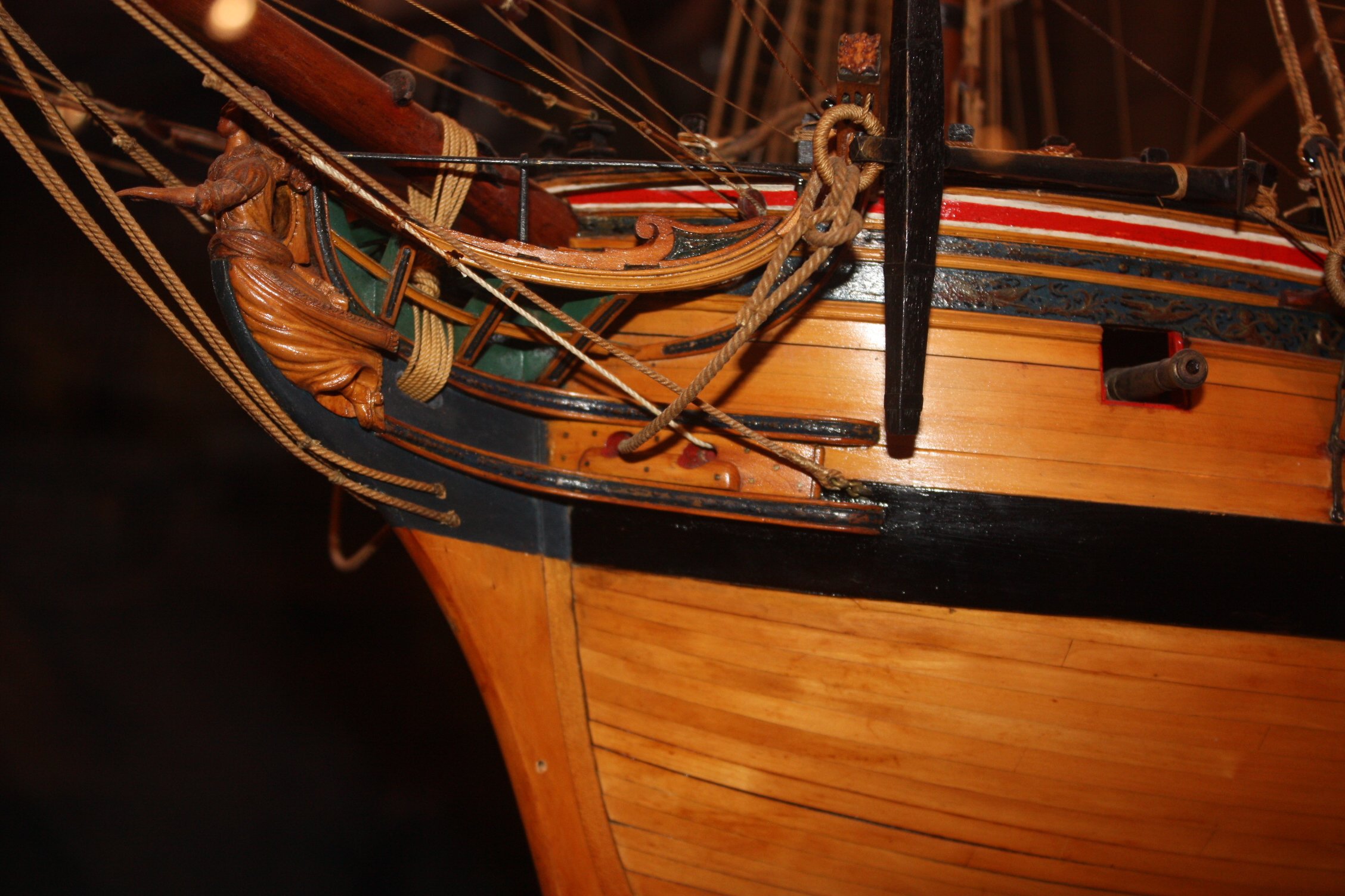
HI David I have 17 photos that I took of the model of Minerva (38) 1780 at Preble Hall in Annapolis and would be happy to send them your way if you wish. The description card they had for her in 2011 follows as well as a closeup of her planking at the bow. Allan


-
Laser cannon bracket
allanyed replied to mediocremodeler's topic in CAD and 3D Modelling/Drafting Plans with Software
Hi MM These are nice photos and credit to you for sharing but how is this related to laser cut cannon carriage brackets? I think more folks will see this and benefit from your nice work if you start another topic on topmast mastheads or include in a build log. Allan -
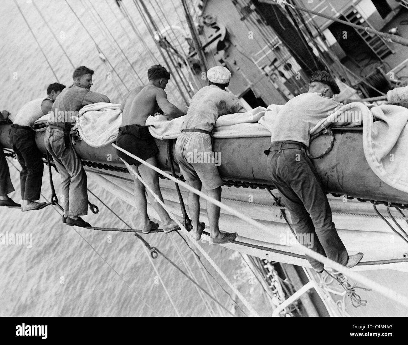
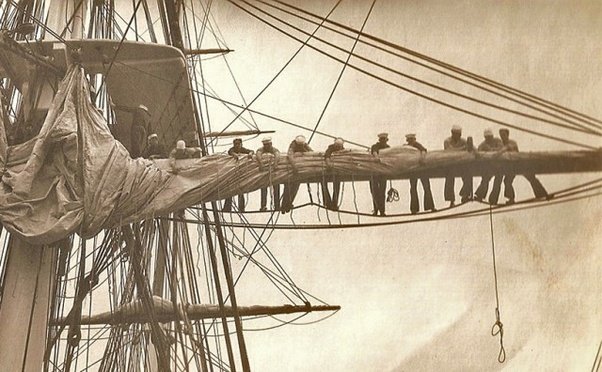
Very interesting point and your test group is a great idea. To add to any confusion that there may be James Lees mentions that the footropes or horses were 2 feet under the yard on page 69 of The Masting and Rigging of English Ships of War, but then on page 70 goes on to say that the stirrups should allow the footropes to hang 3 feet below the yard. Looking at the photos below, this makes some sort of sense. Where as the stirrups were probably pretty much the same on a given ship, not all seamen were the same height so maybe topmen assignments were partially based on their height just as strength was a consideration in assignments. The below are photos thus obviously more modern times, but may fit the discussion. Hopefully the sailors between the stirrups were the taller ones. 😀 Allan

-
Overall really nice model and your metal work is some of the best we have seen. For the future, in the past couple years, thanks to builder/author Ed Tosti, for some parts I have found copper to be better suited than brass. It solders very nicely and can be blackened instantaneously after being fixed in place on the model with diluted liver of sulfur then rinsed without staining the wood. Allan
-
Post #31 from Ross is spot on. If you take his advice you will be happy with the result. The main thing is to be sure you do not get the lifting from excessive edge bending so there is not excessive sanding needed. Allan