James H
-
Posts
6,122 -
Joined
-
Last visited
Content Type
Profiles
Forums
Gallery
Events
Everything posted by James H
-
 That looks ok to me! Don't beat yourself up. When sanded, you'll have a nice surface to add the second layer.
 -
Welcome back to the hobby, and of course to MSW 😁
-
Glad that worked for you. Had loads of probs in past with stuff remaining tacky for a while but thankfully a little white spirit always relieves the pain 😁
-
Not at all. It's aimed at a total beginner, as is the Fifie Welcome to MSW!
-
Is the timber walnut? I know when I add poly varnish, it can take 2 or 3 days to fully dry as it the walnut seems impervious. Maybe leave it another 48hrs and see. You could use some rag dampened with white spirit and gently wipe them down, then leave for a while.
-
As it says, if you have anything useful to our community, both to laser cut or 3D-print, add it to this topic and I'll add to this initial post
-
- 2
-

-
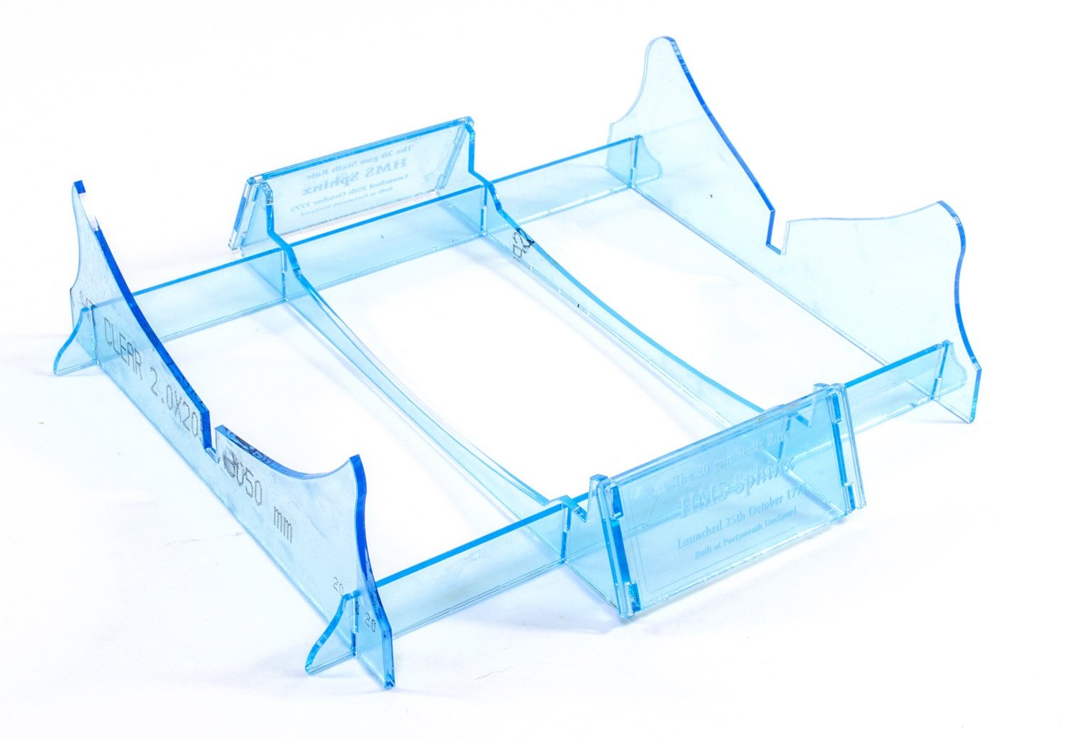
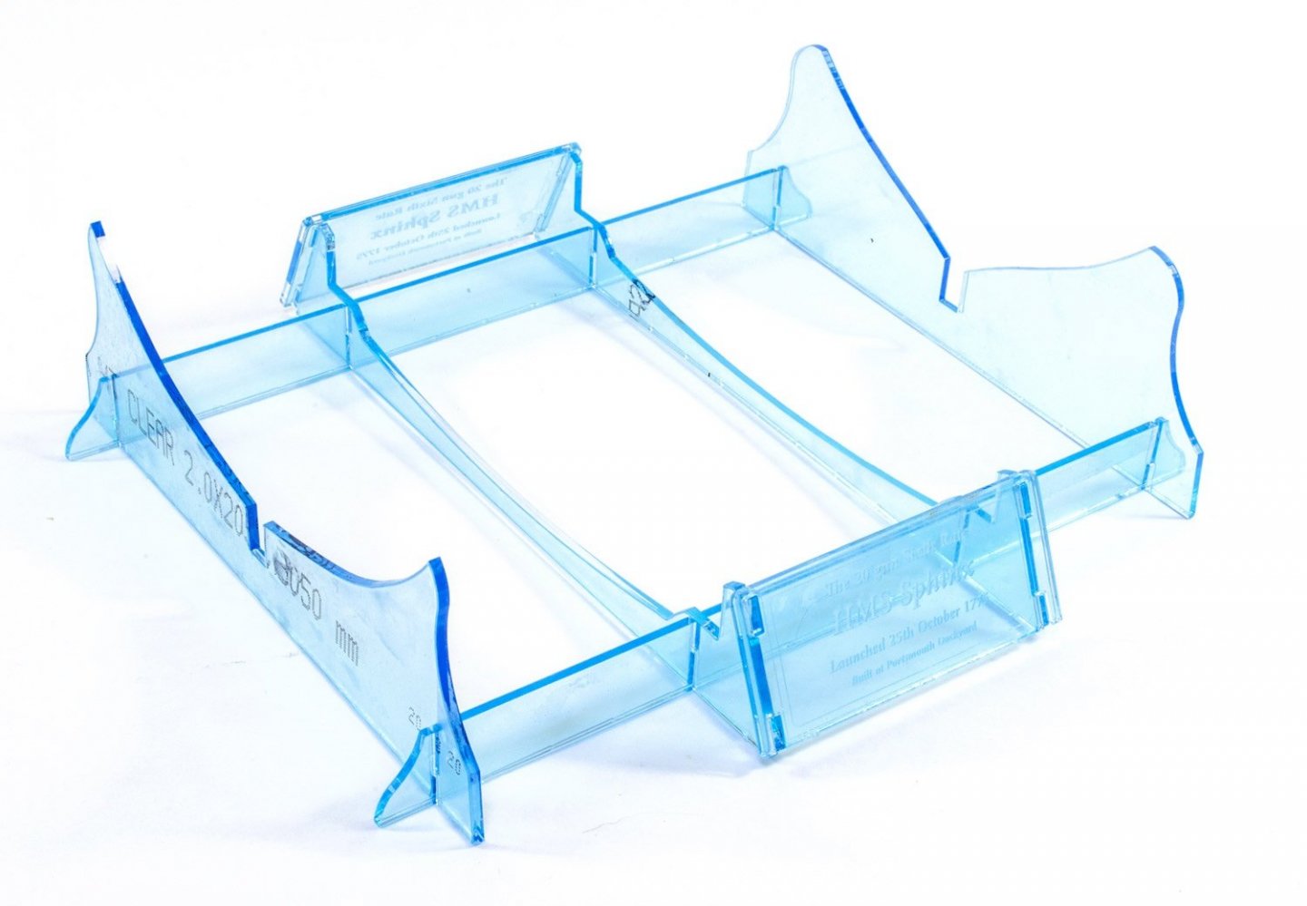
Way too much rich food, so I need to trim down a little. With regards to the Sphinx stand, this is the one supplied. I left the blue film on for assembly shots, but there will be pics of it without that film when done.
-
Such a shame, but if something is sapping your enthusiasm, then shelve it until you feel differently, and then maybe use as a filler project between others. Perhaps after Badger, maybe the Sphinx kit? (no, I'm not on commission earnings! 😂)
-
Yes, fully masted and rigged as per other VM kits. I'm fresh back from hols only 2hrs ago and already working on the prototype again.
-
Ooh, what's this?
-
I built that 1:72 Matchbox kit about 20yrs ago as a prelude to starting wooden ships, and I loved it. Amazing to see something in 1:48 like this.
- 321 replies
-
- 7
-
-
- Finished
- Flower-class
- (and 1 more)
-
I only wish. I'm now on starting Sphinx shroud pendants and my room is blistering hot. It's almost unworkable for I need to stay in there for as long as I can before it makes me feel drained and sick.
-
NEW AT VANGUARD MODELS! - 'BUY NOW, PAY LATER' (Pay In Three) from PayPal. I've been helping Chris with his website and PayPal have really been bugging us with rolling out this system for VM customers. VM satisfies their criteria which allows customers to make purchases from £30 to £2000 using a three-payment system. Once you go to PayPal checkout, you will have an option to choose this. The total cost is split into three equal payments at 0% interest, and then the remainder is paid on the due dates over the following two months. The great news is you of course get your items shipped straight away as you would if you'd paid up-front. That'll help break up some of those costs we all have when it comes to buying our kits and stuff! https://vanguardmodels.co.uk https://www.paypal.com/uk/webapps/mpp/paypal-payin3/faq There are some territory restrictions, but can't remember them at moment!

-
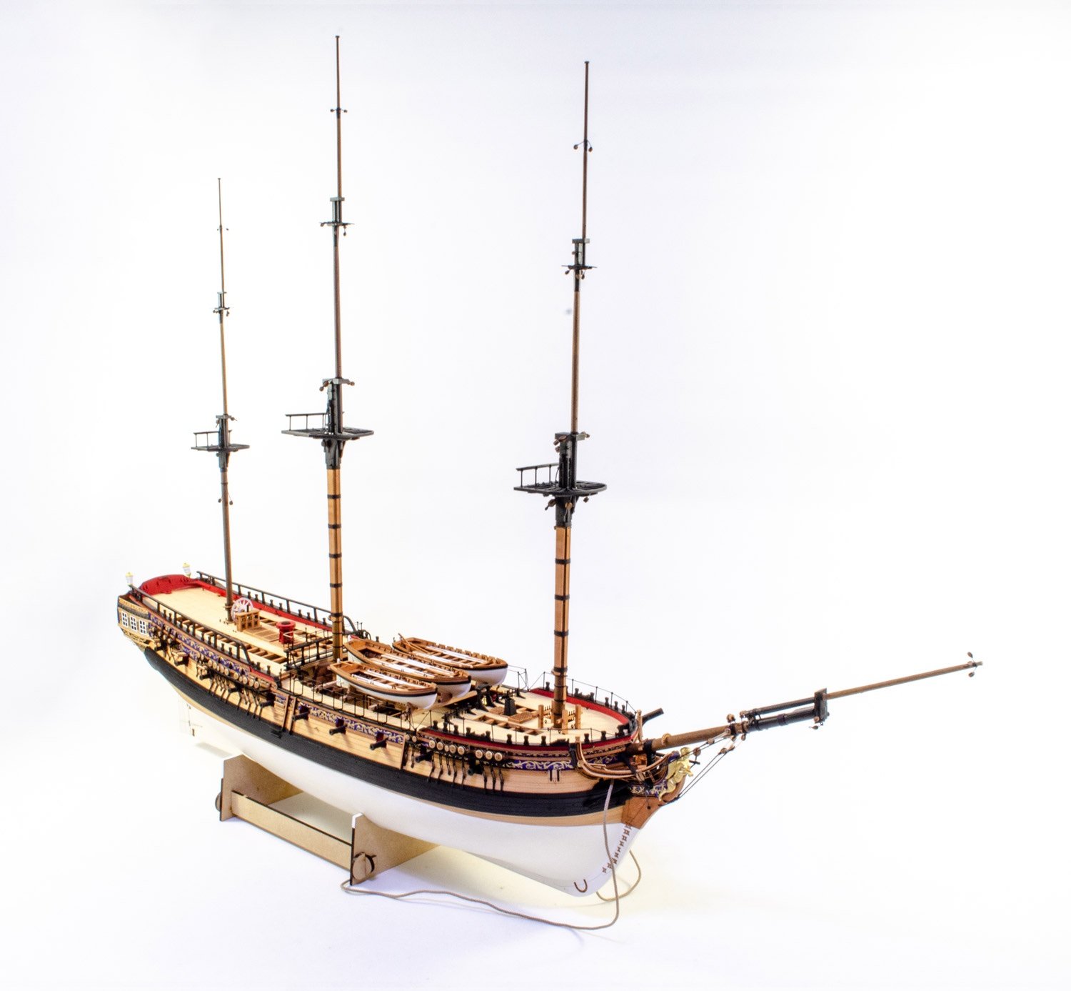
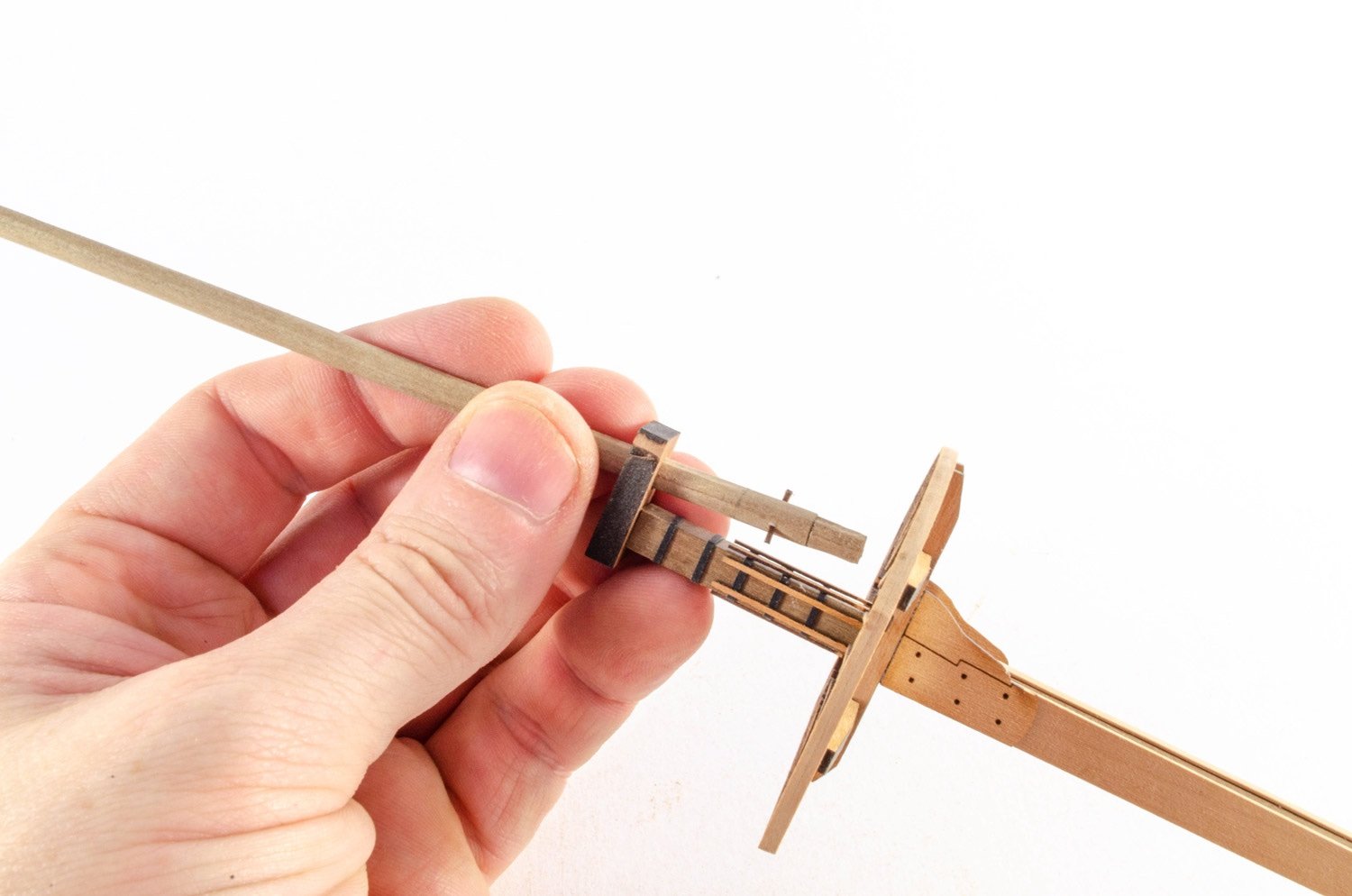
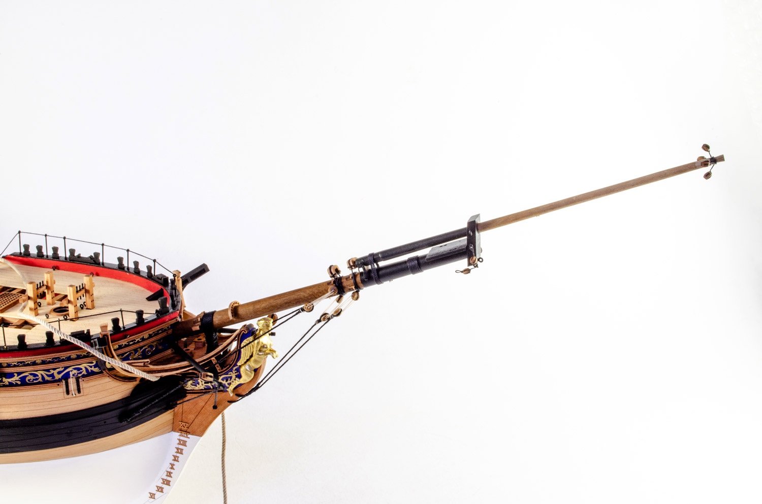
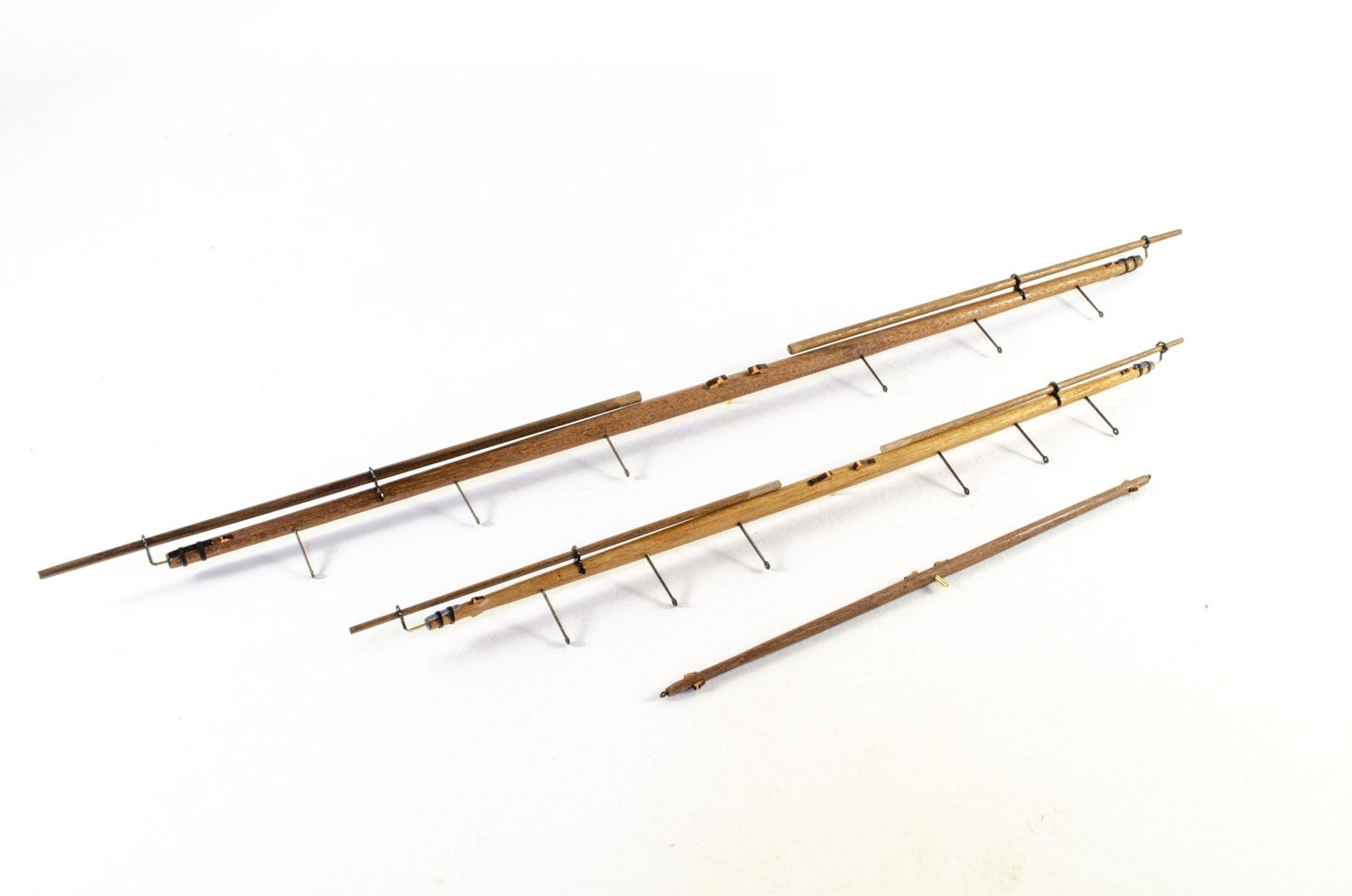
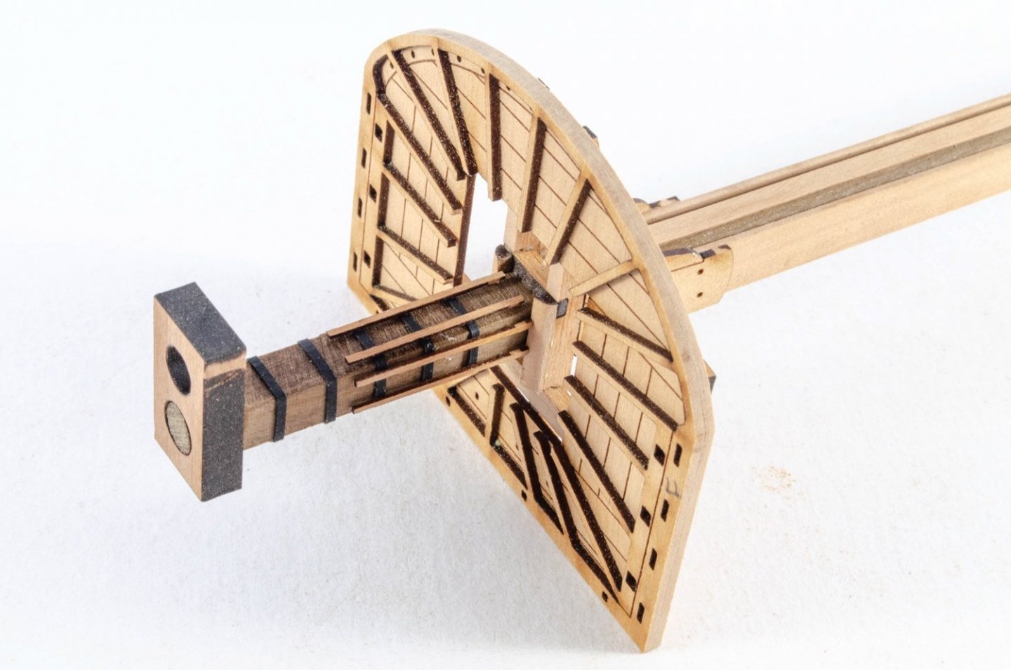
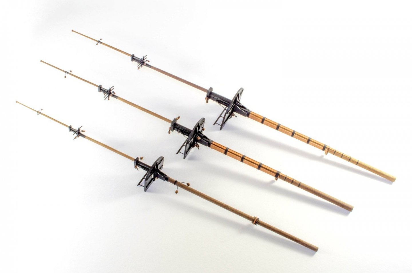
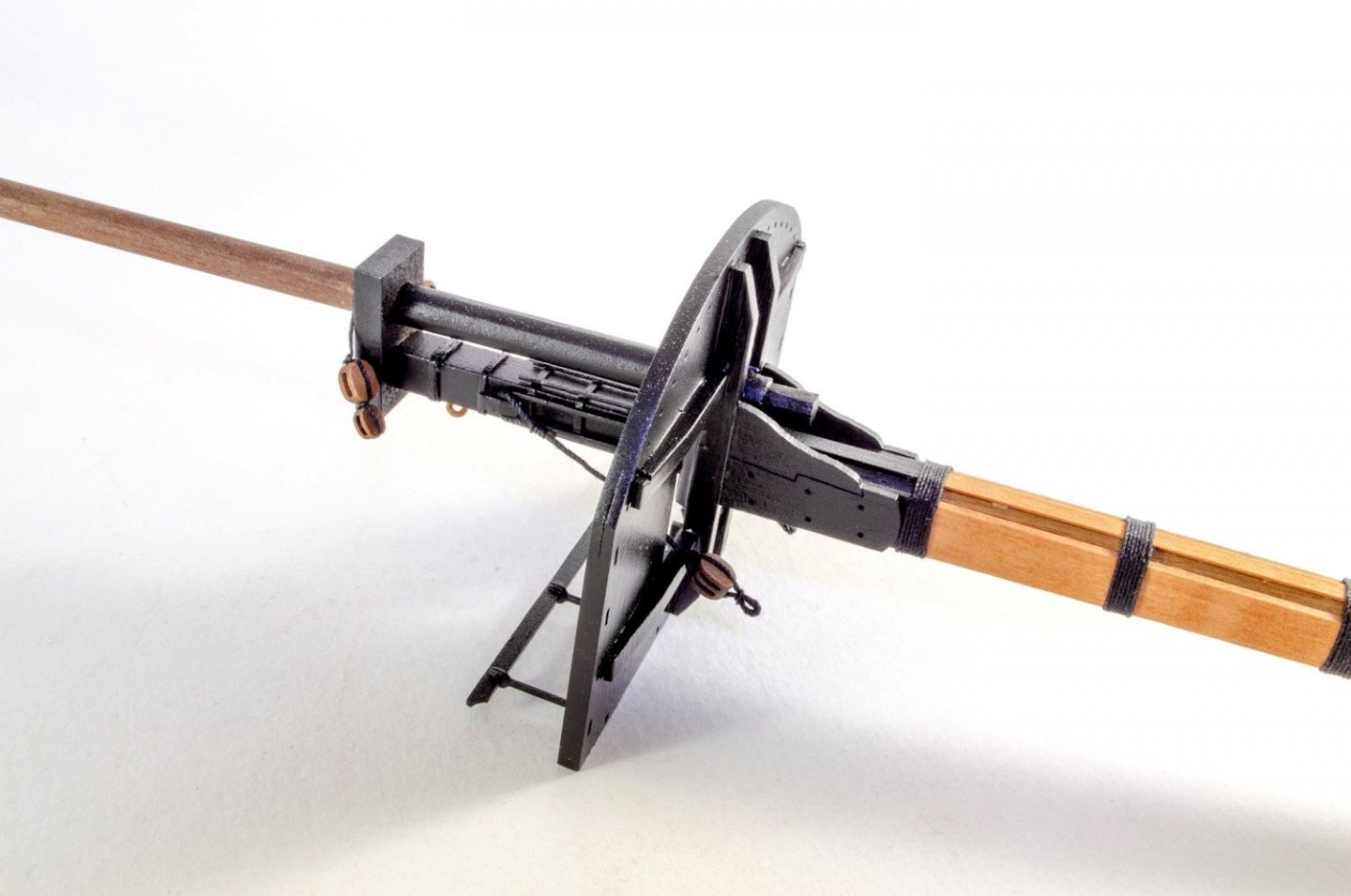
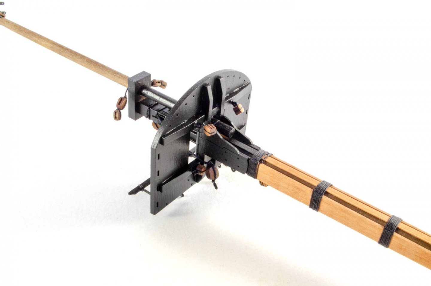
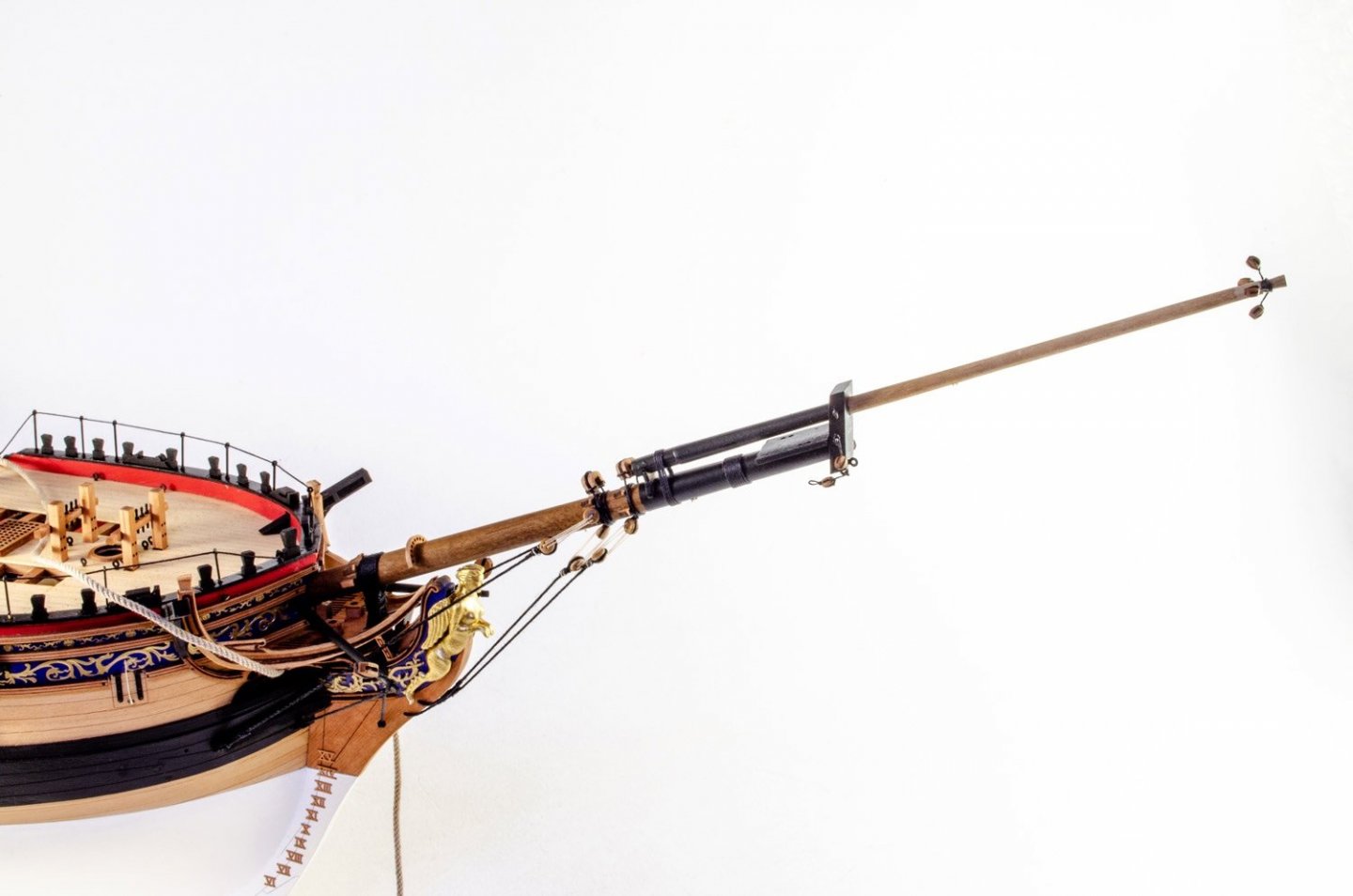
Here's my last update before the final completion images. The masts are pretty straightforward. Cartridge paper is used for the iron banding, the battens then fitted over these. When complete, the masts are varnished and then sections painted black before then fitting out with rigging blocks etc. For this model, I've used the optional pear blocks (except for deadeyes as the pear weren't in stock when I started). All yards are then built, including mizzen gaff, ensign pole etc. These will be fitted out as soon as the paint is dry. Whilst waiting for paint drying, I fitted the bowsprit and rigged the shrouds and stays after first adding the gammoning. Boomkins are also rigged. And this is the result so far. Catch you when she's finished...


- 355 replies
-
- 42
-
-

-
- vanguard models
- Sphinx
- (and 1 more)
-
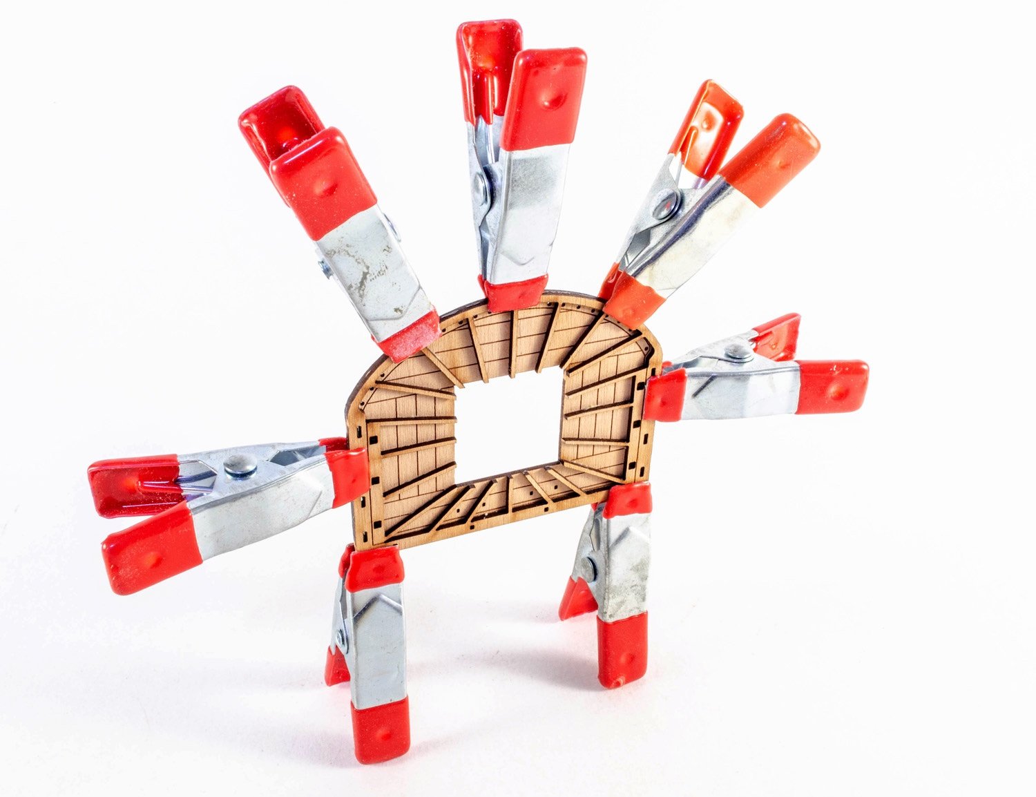
Beautiful stuff 🥰 Love the heavy metal to hold stuff down and all those clamp forceps! 😝
- 47 replies
-
- 2
-
-
- Modellers Shipyard
- Perseverance
- (and 1 more)
-
Painting Problems
James H replied to Neil10's topic in Painting, finishing and weathering products and techniques
Seal the filler using a varnish or primer before painting. Painting on top of filler will generally mean a bad finish. -
This is a whole world away from the Hachette partwork now. Quite a different beast.
-
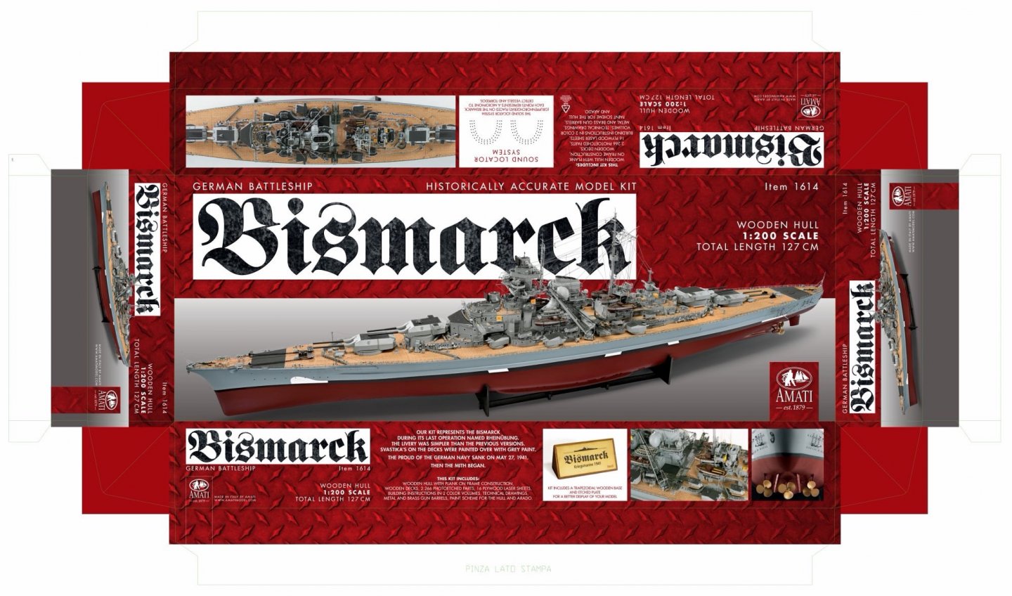
Bismarck is now shipping to retailers etc. with Amati's own online store carrying it from around September, so not long to wait now. MSW will be having its own in-box review here too. This is the box-art for the kit:
-
Slightly off topic, but for those who were asking about Bismarck, this is now shipping to retailers, with Amati's own online store carrying it from September. That now moves a lot of the blockage with Victory, so hoping this can continue this summer 🤞
-
And we all know better than to listen to that sort of folk on FB I was really liking your work on this and was surprised when it stopped. Please restart this one. Plenty here will like to follow it, including me.
- 322 replies
-
- 14
-

-
-
- enterprise
- caf
- (and 1 more)
-
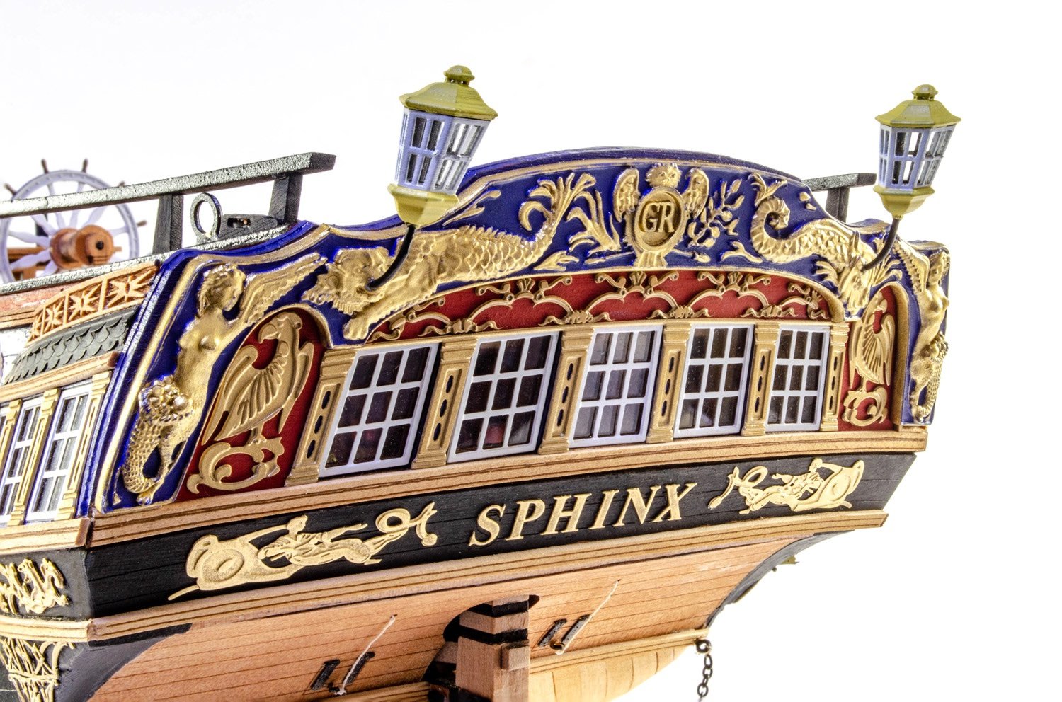
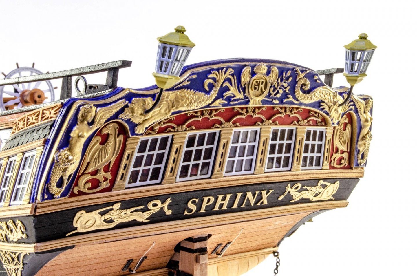
I'm still beavering away with masts and stuff, but the lanterns have arrived, and they are now fitted. These are 3D-printed ones with the correct rake and acetate internal glazing. Very nice!
- 355 replies
-
- 32
-
-
- vanguard models
- Sphinx
- (and 1 more)
-
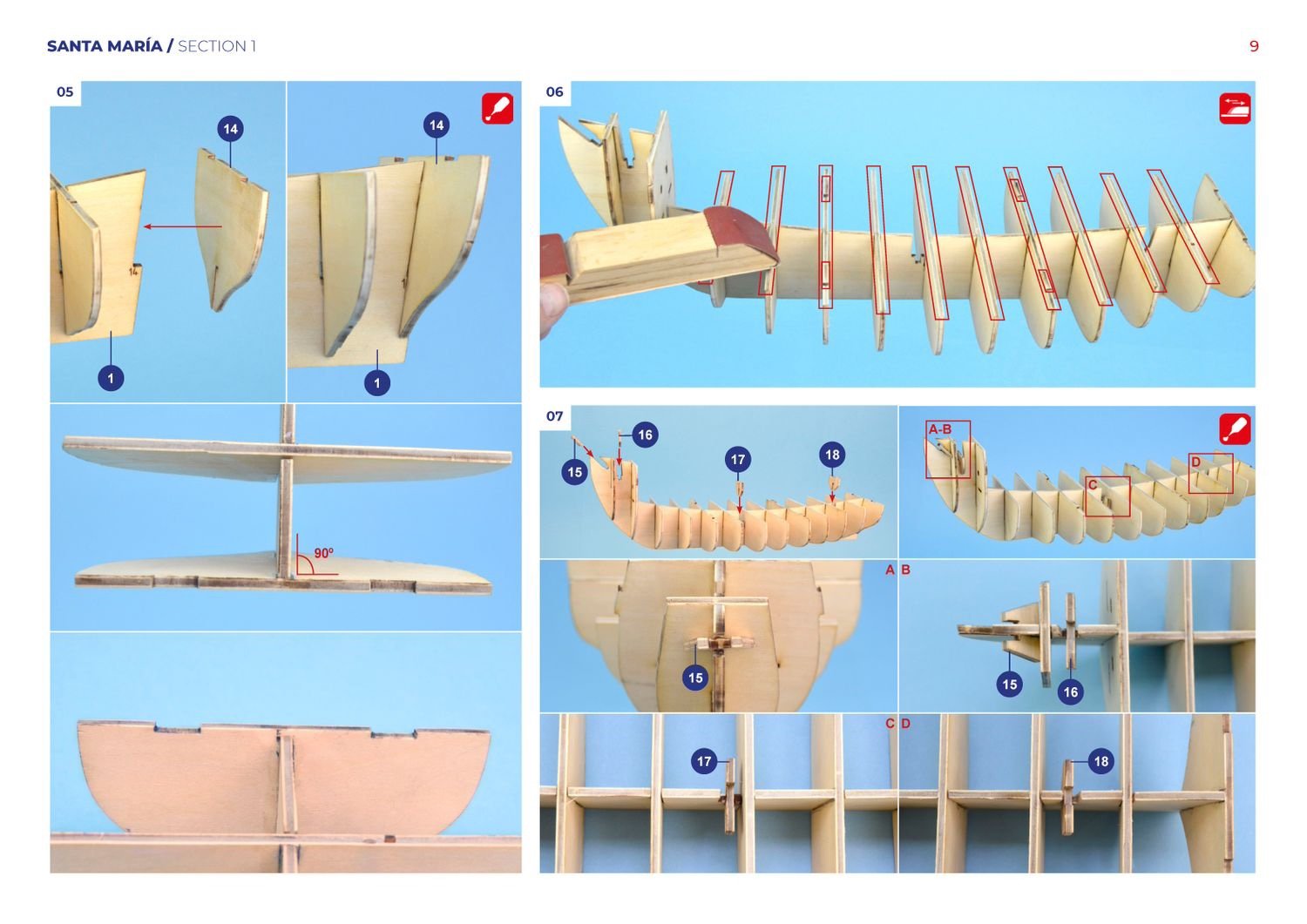
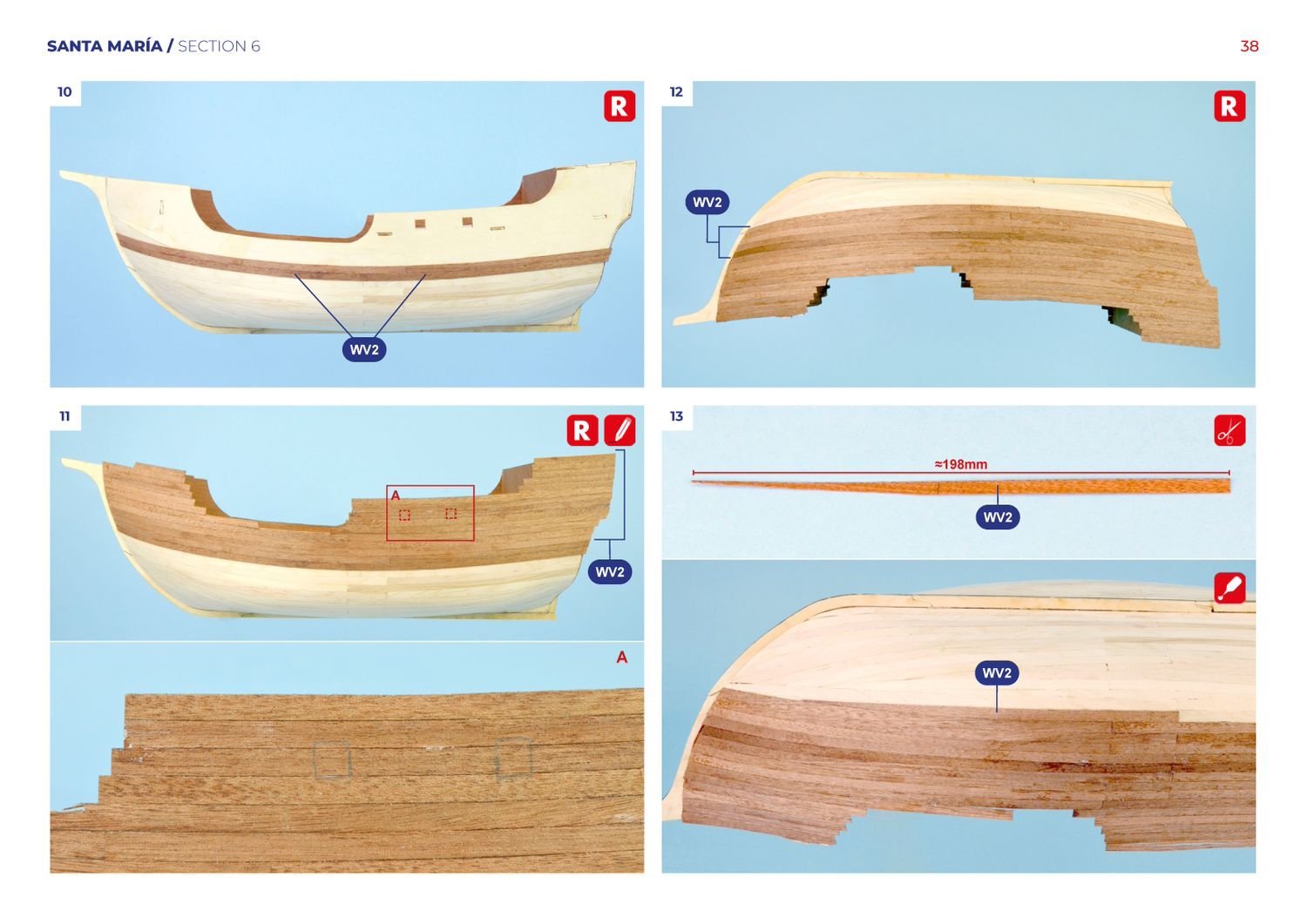
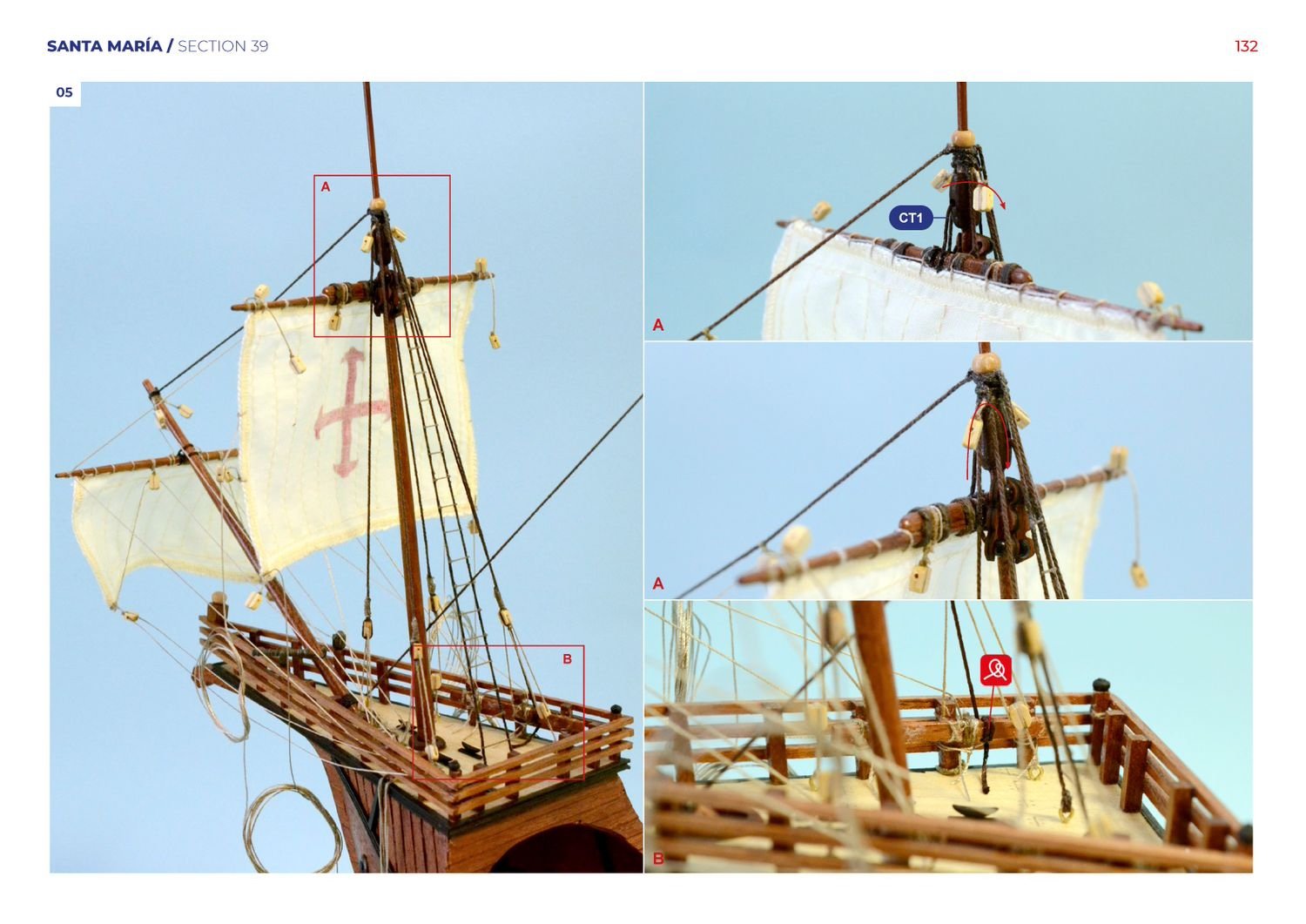
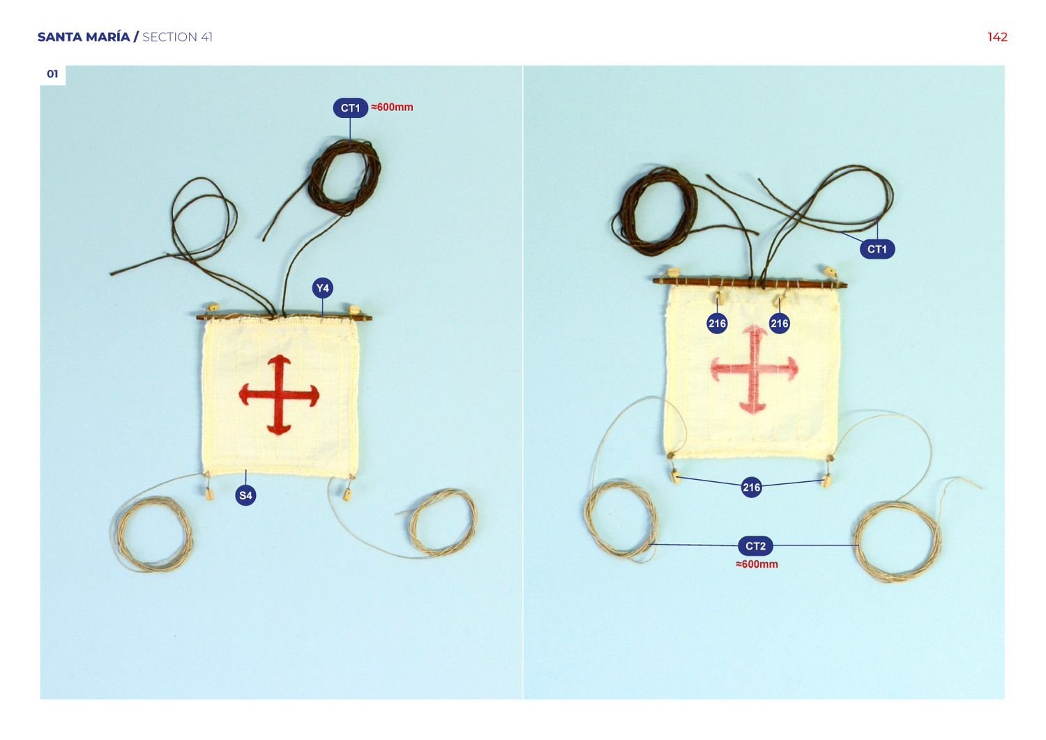
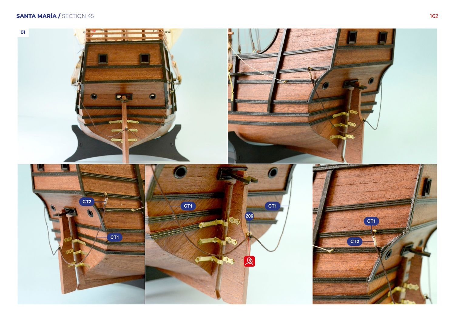
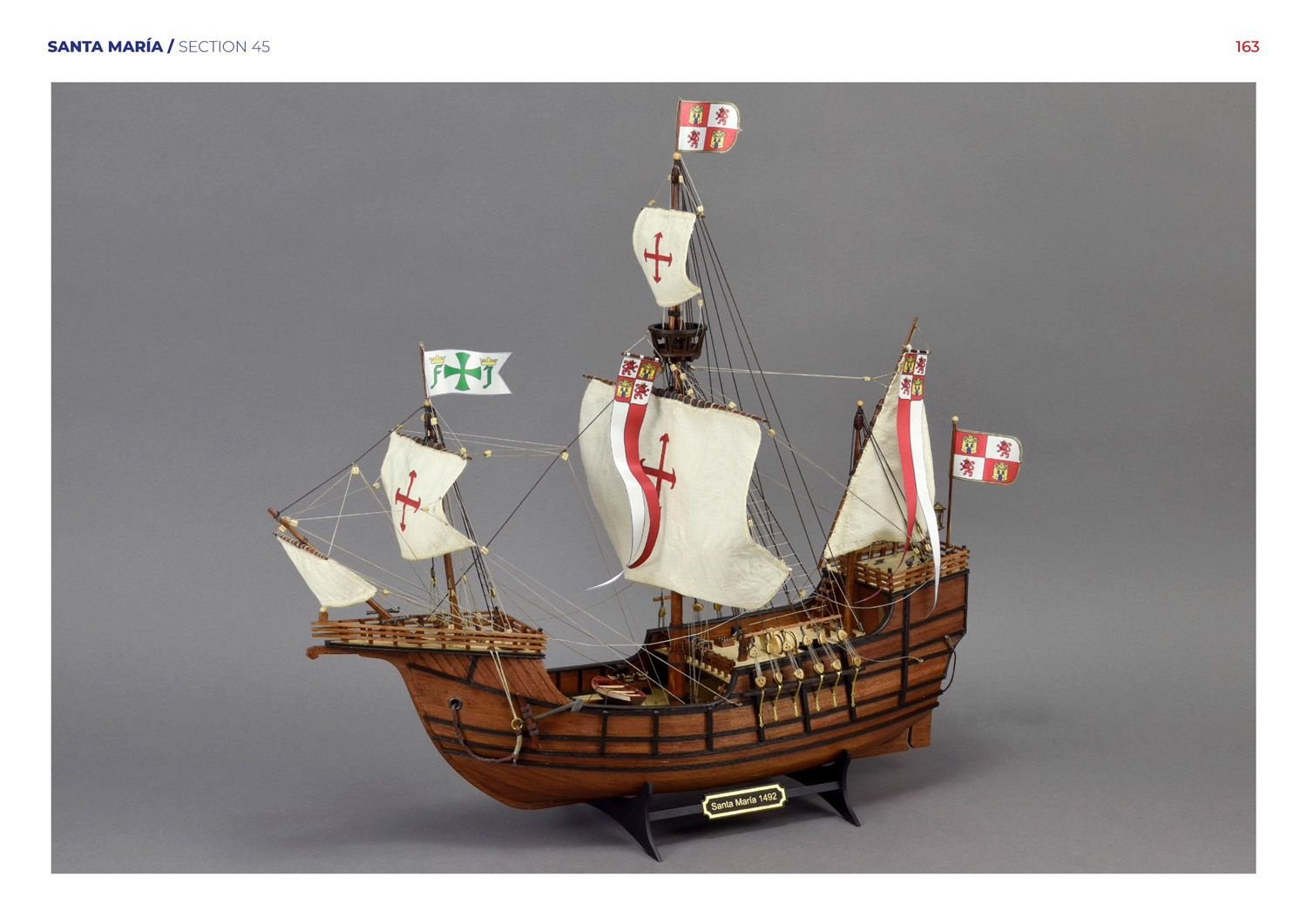
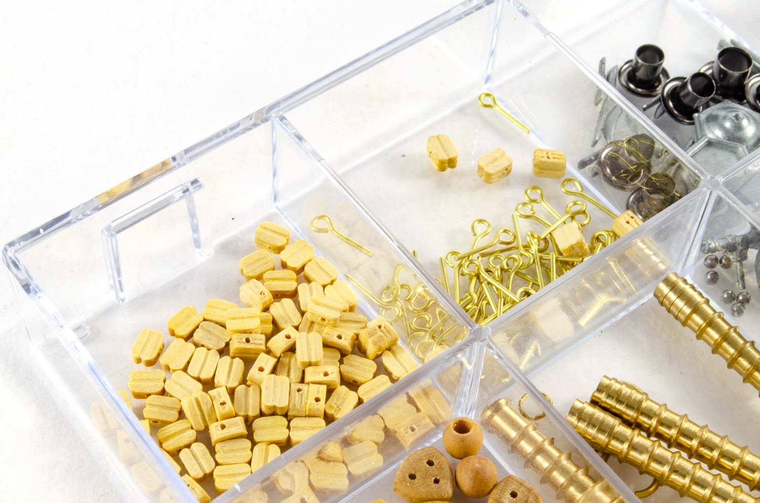
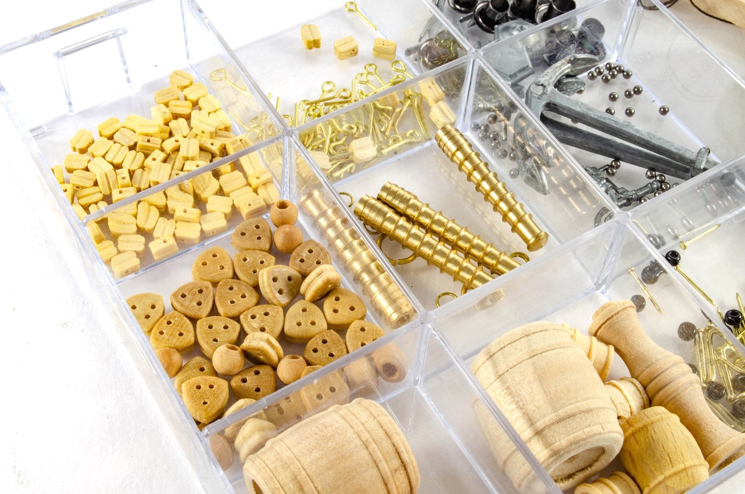
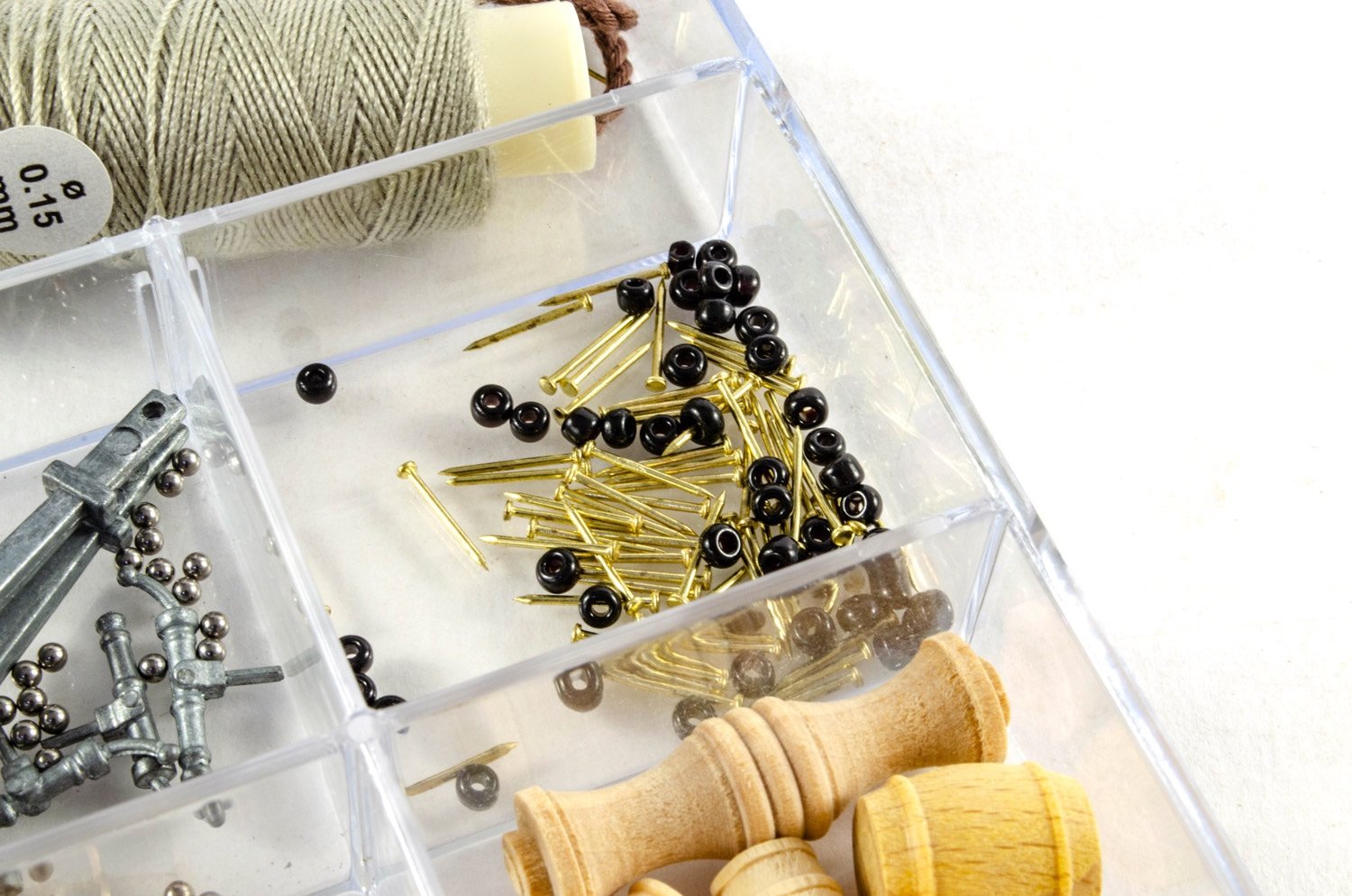
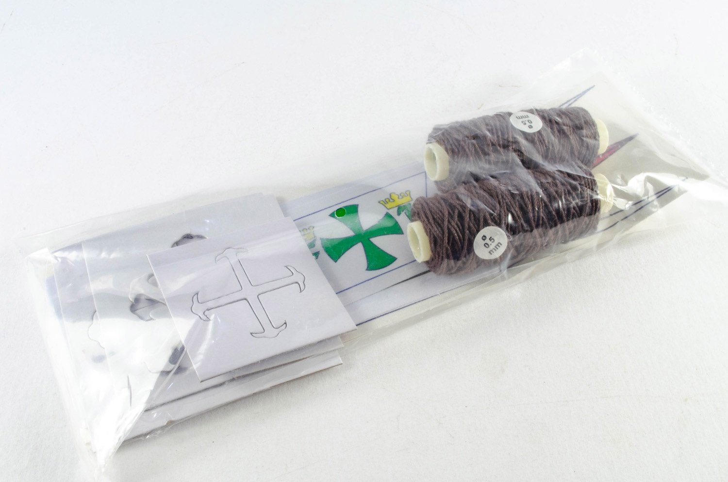
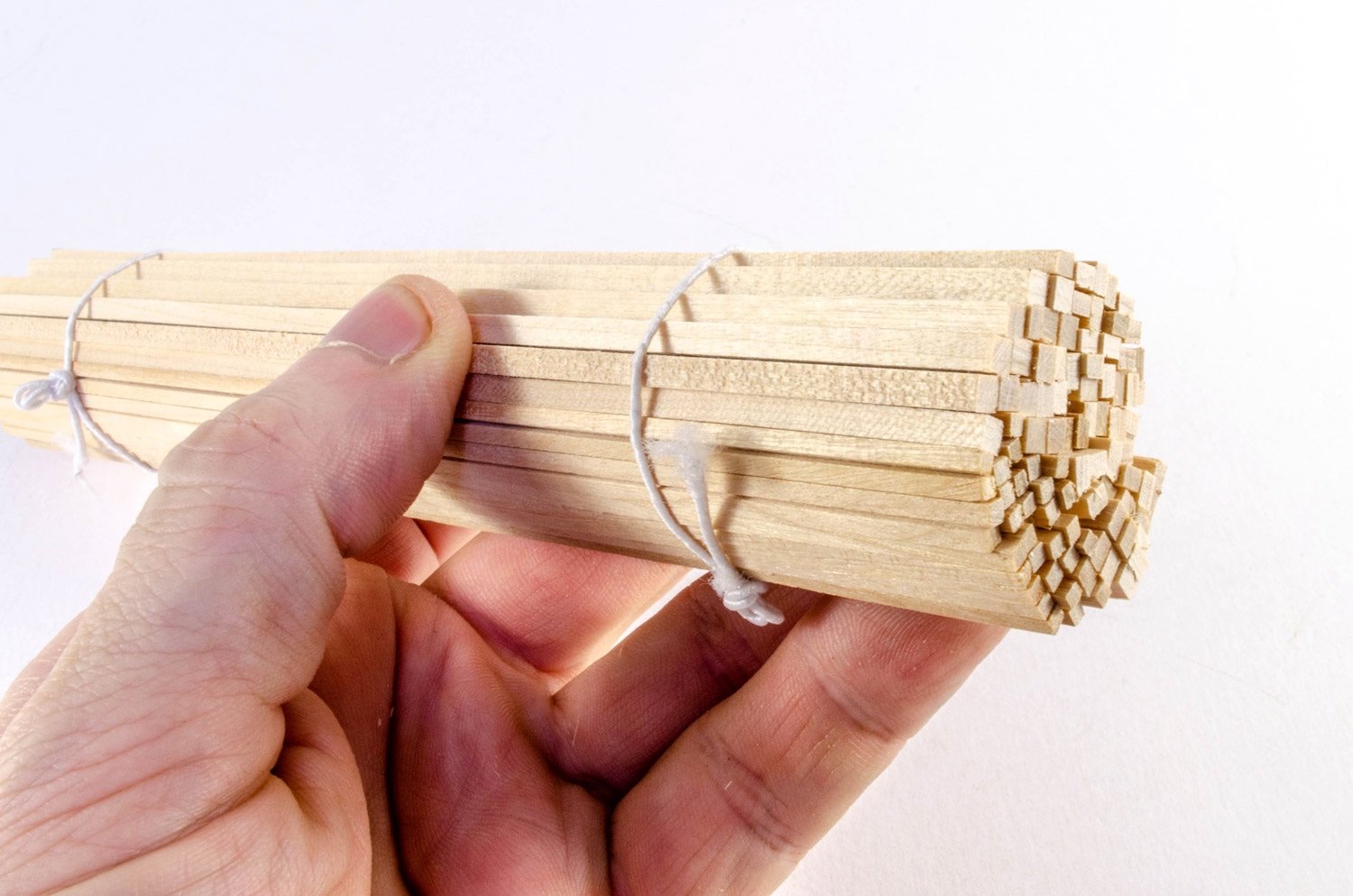
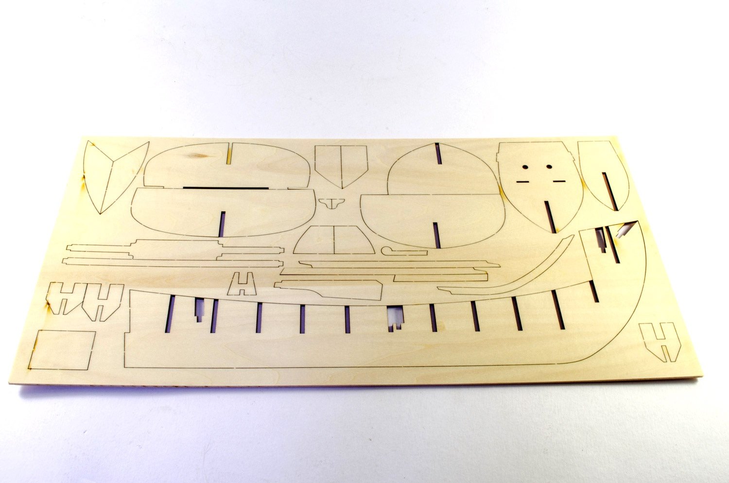
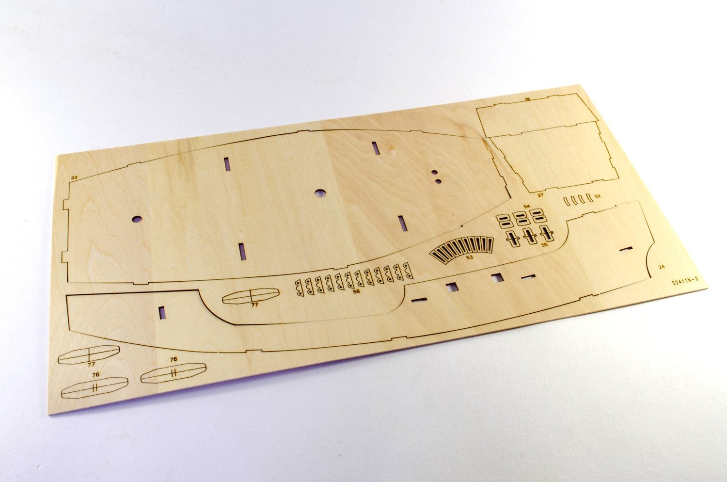
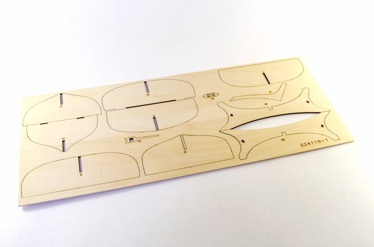
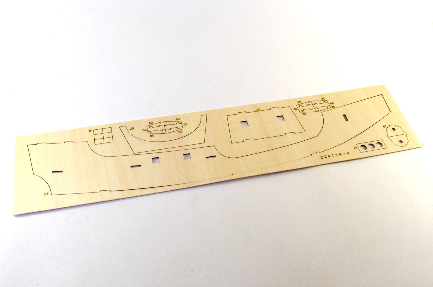
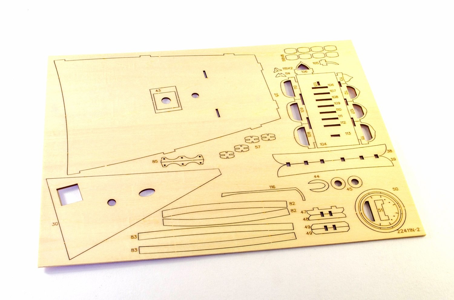
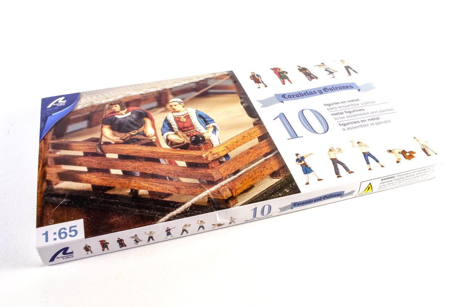
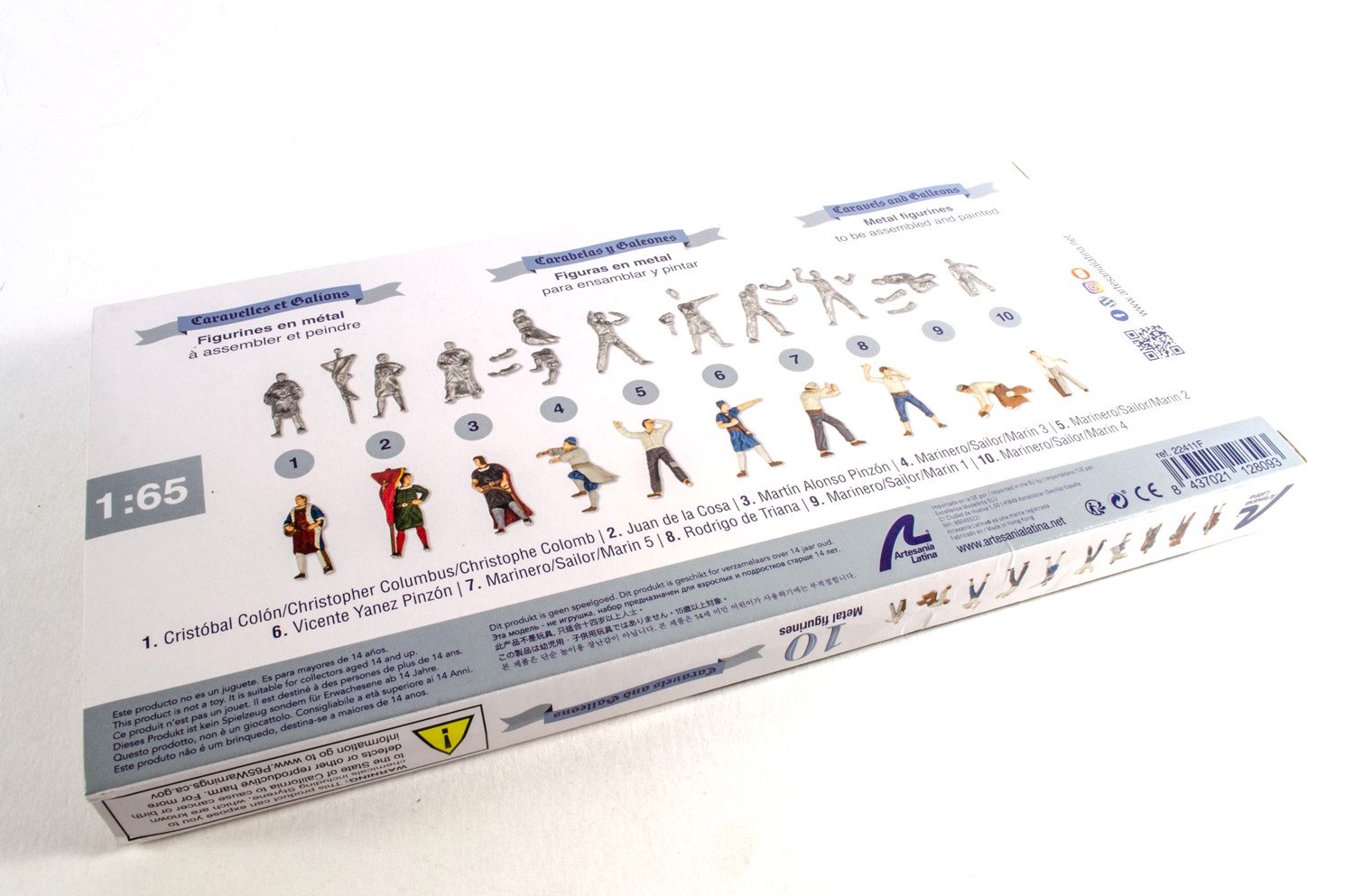
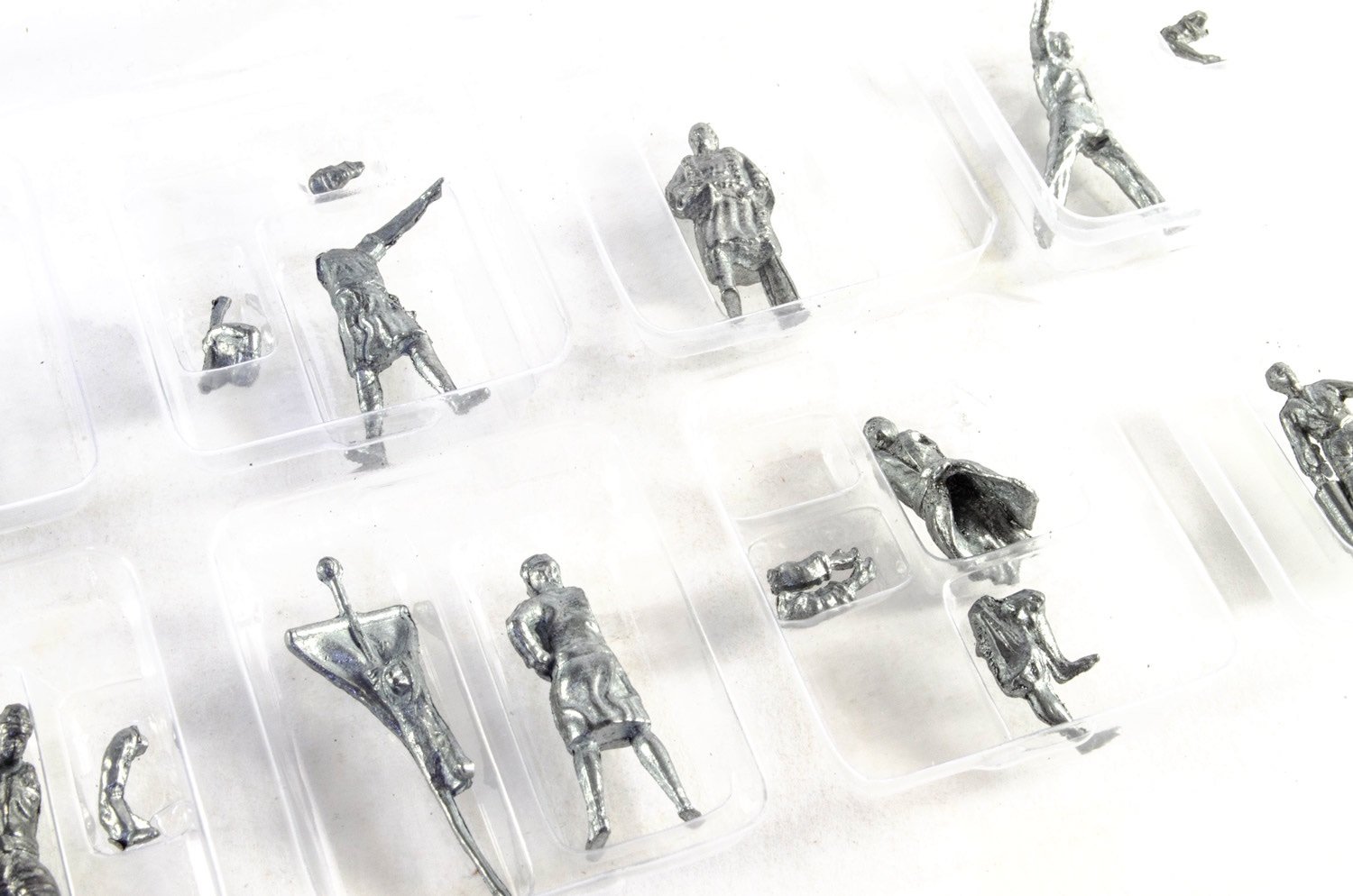
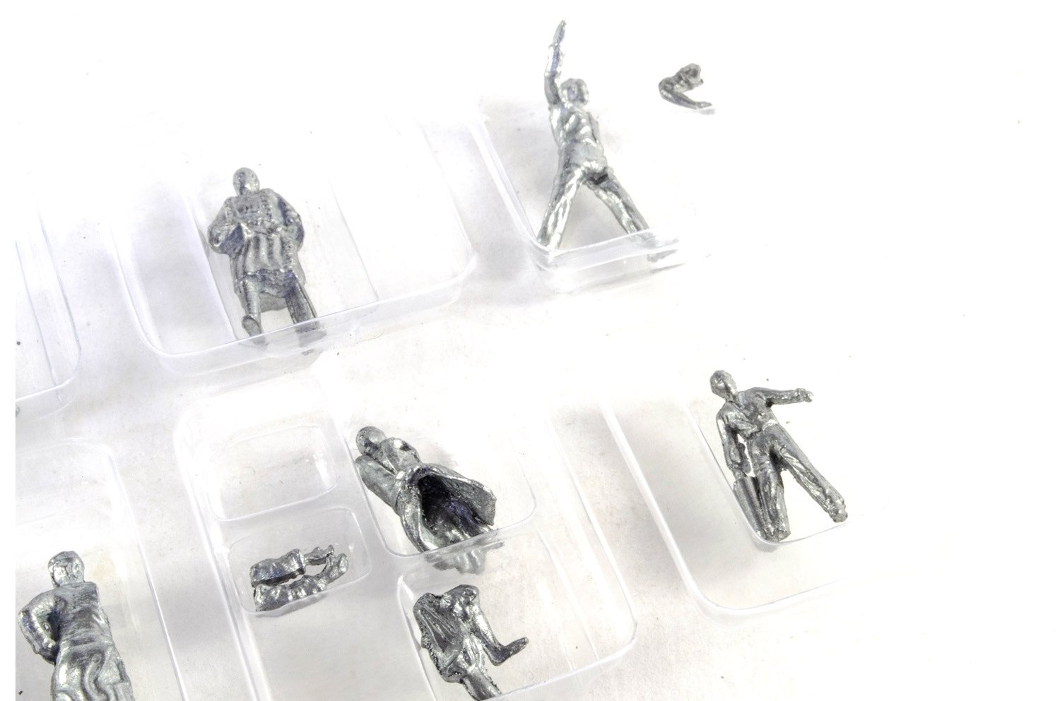
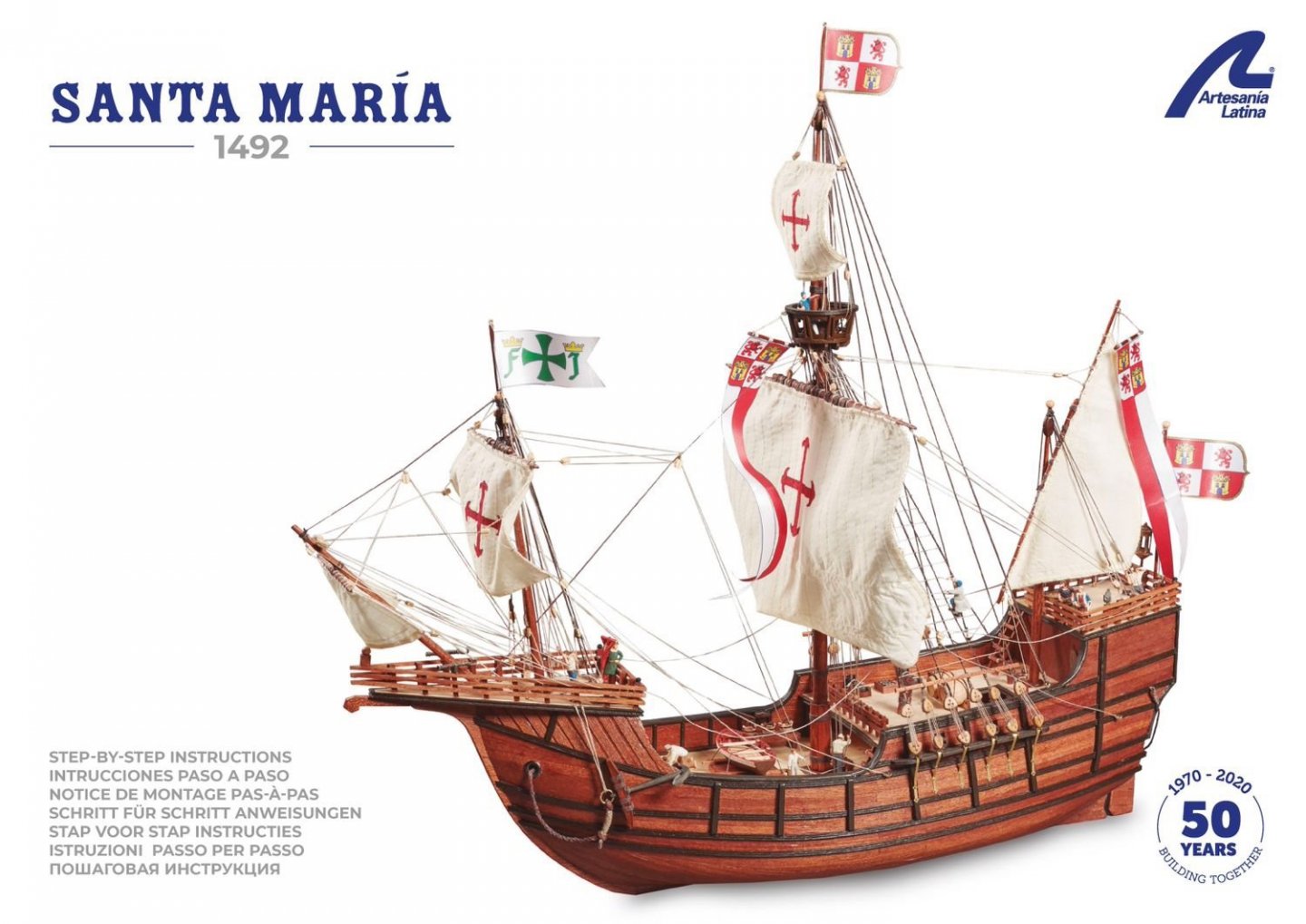
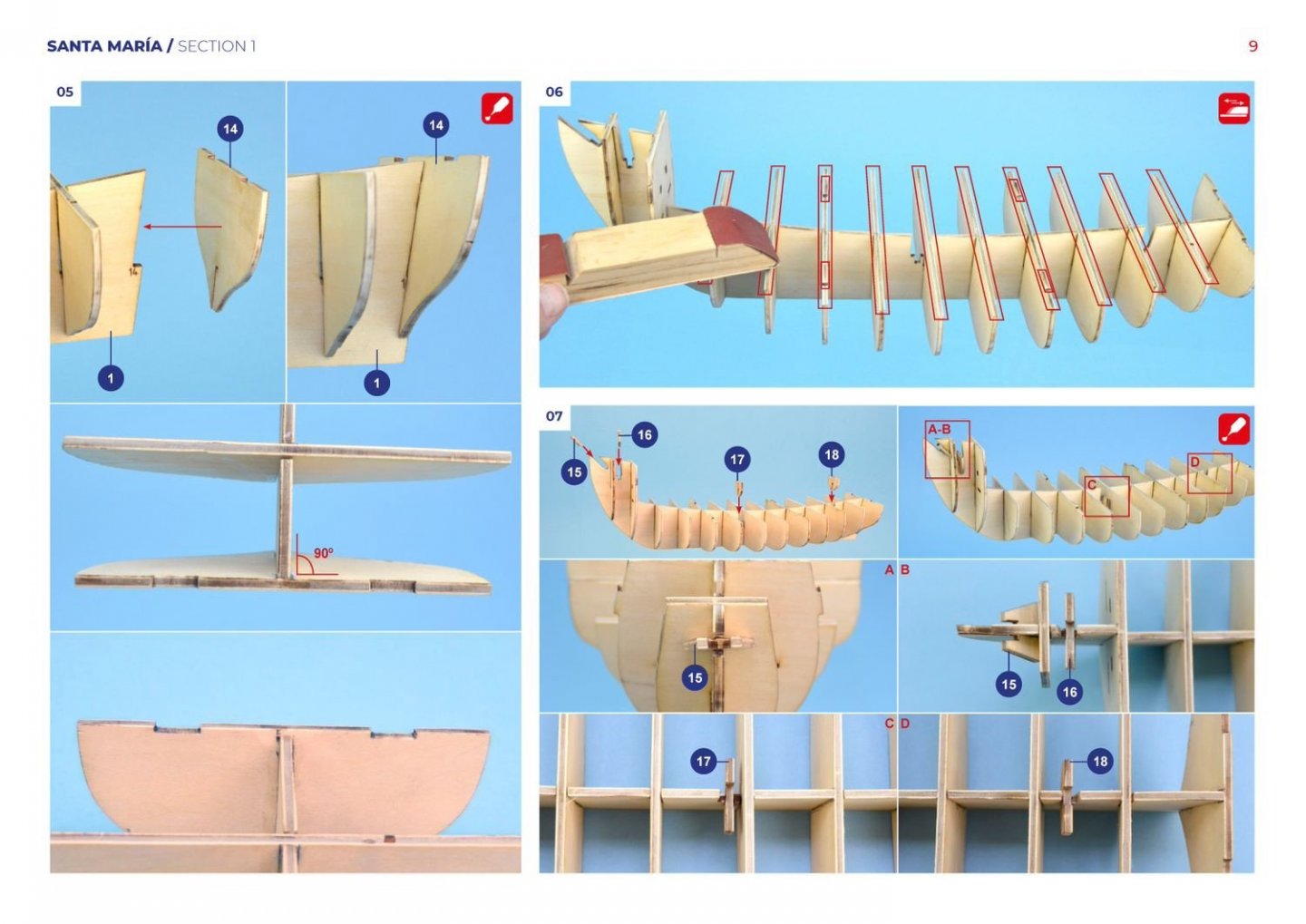
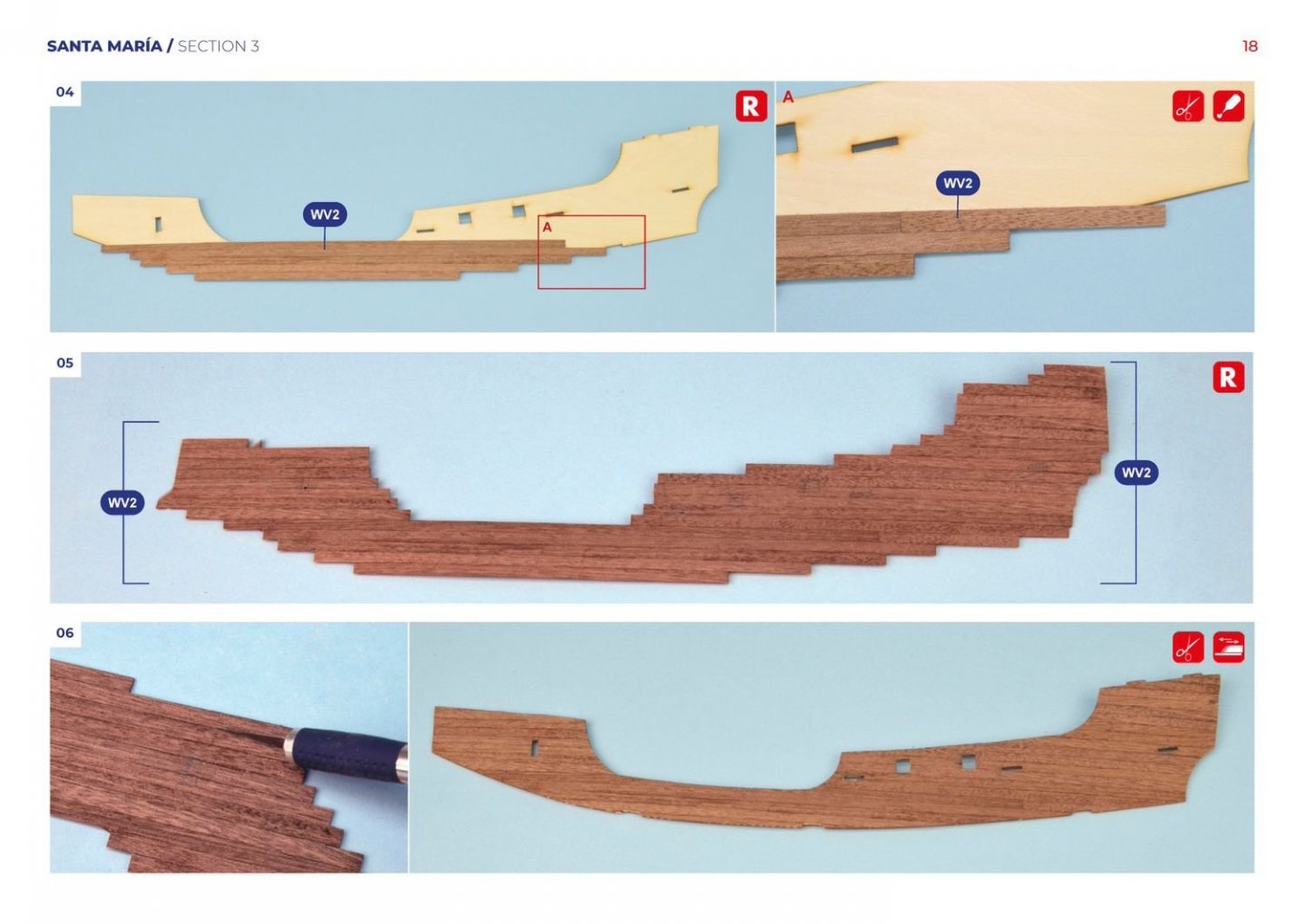
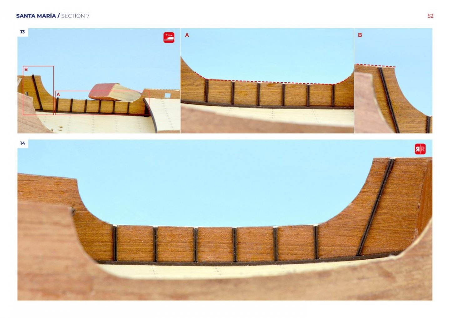
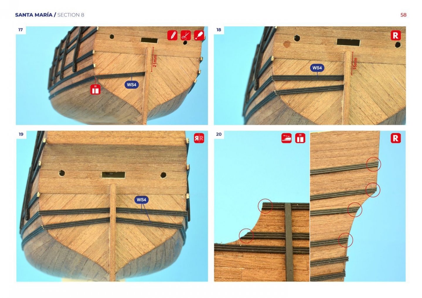
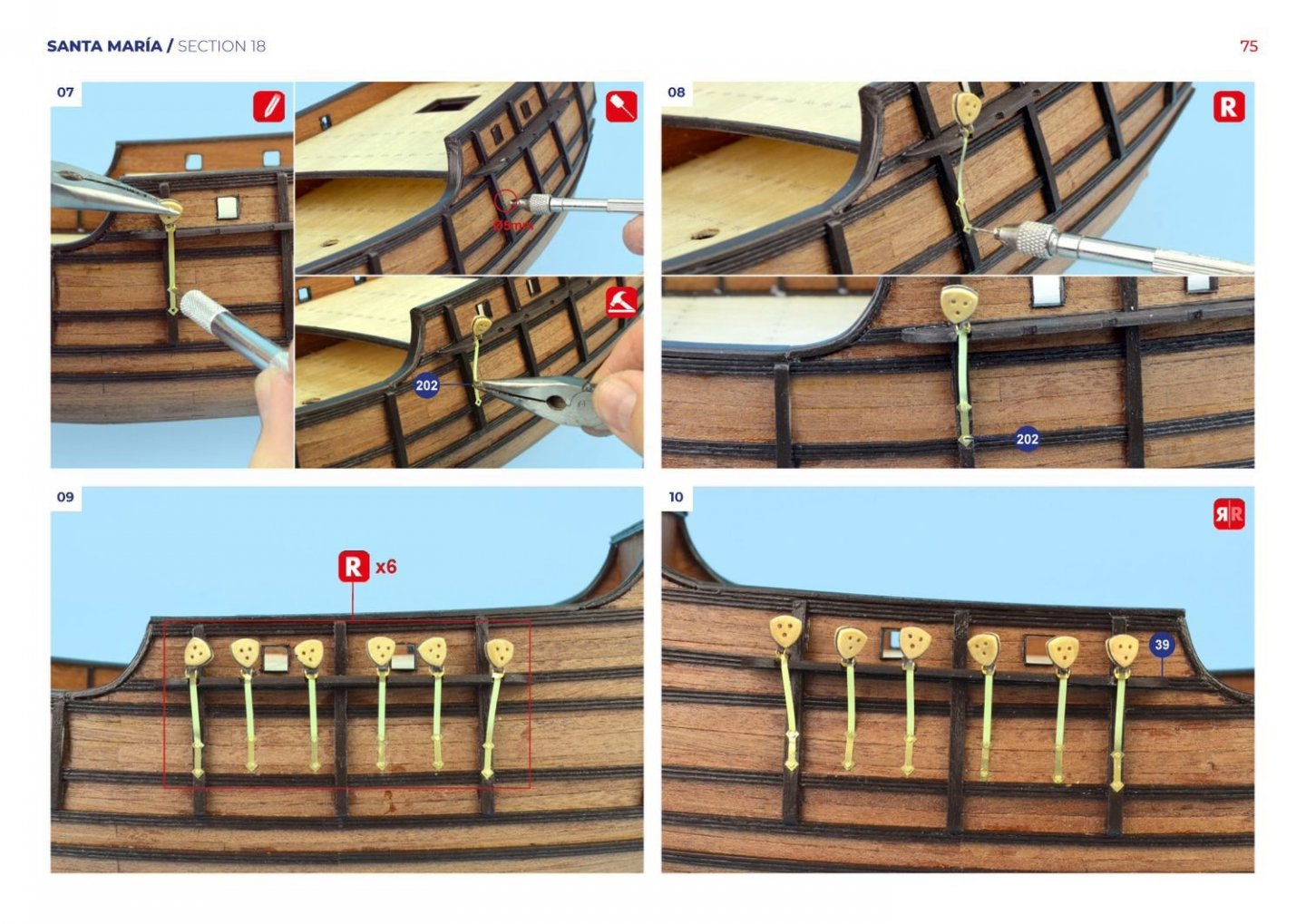
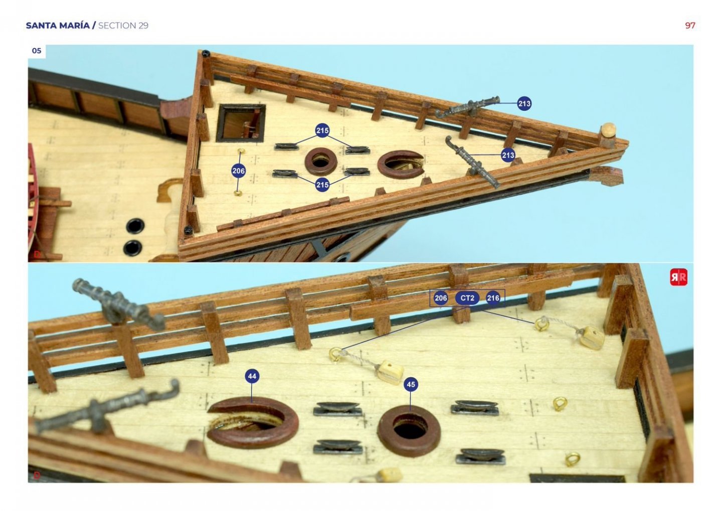
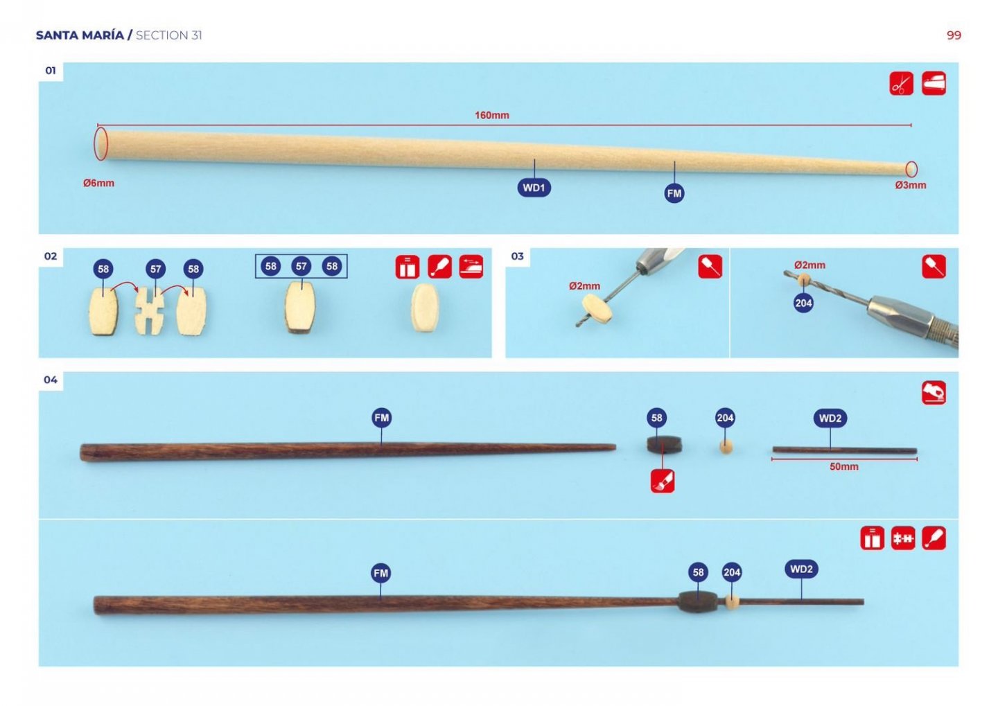
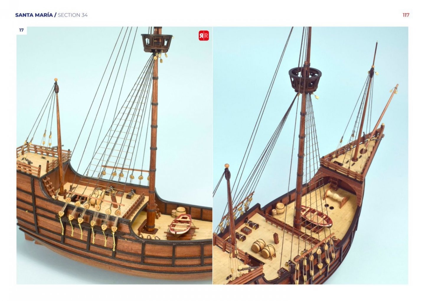
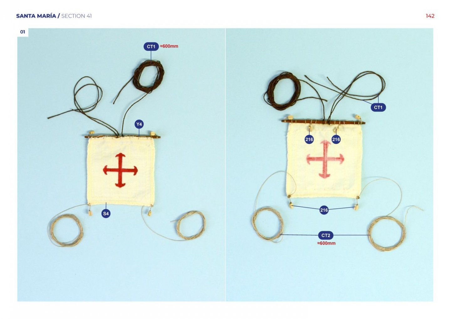
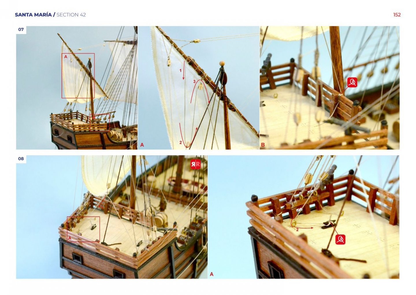
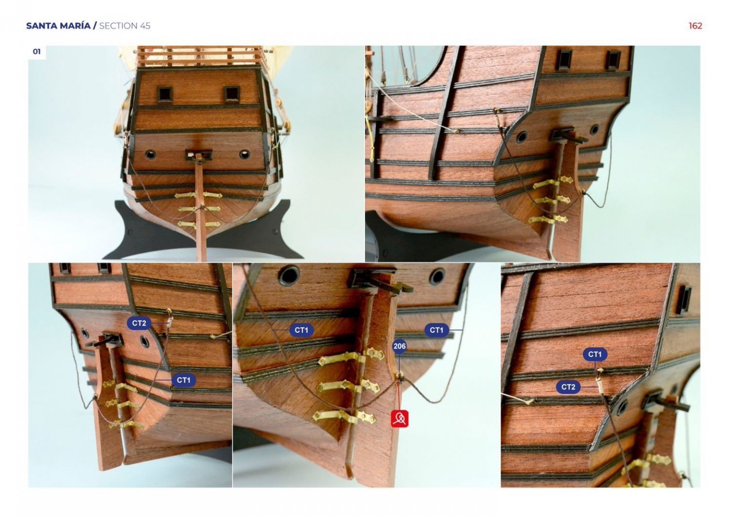
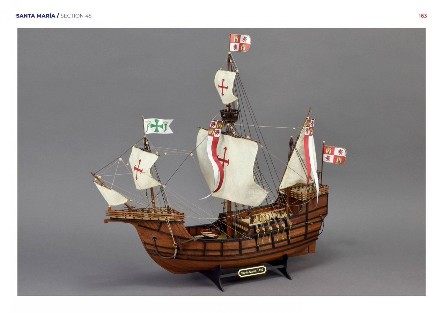
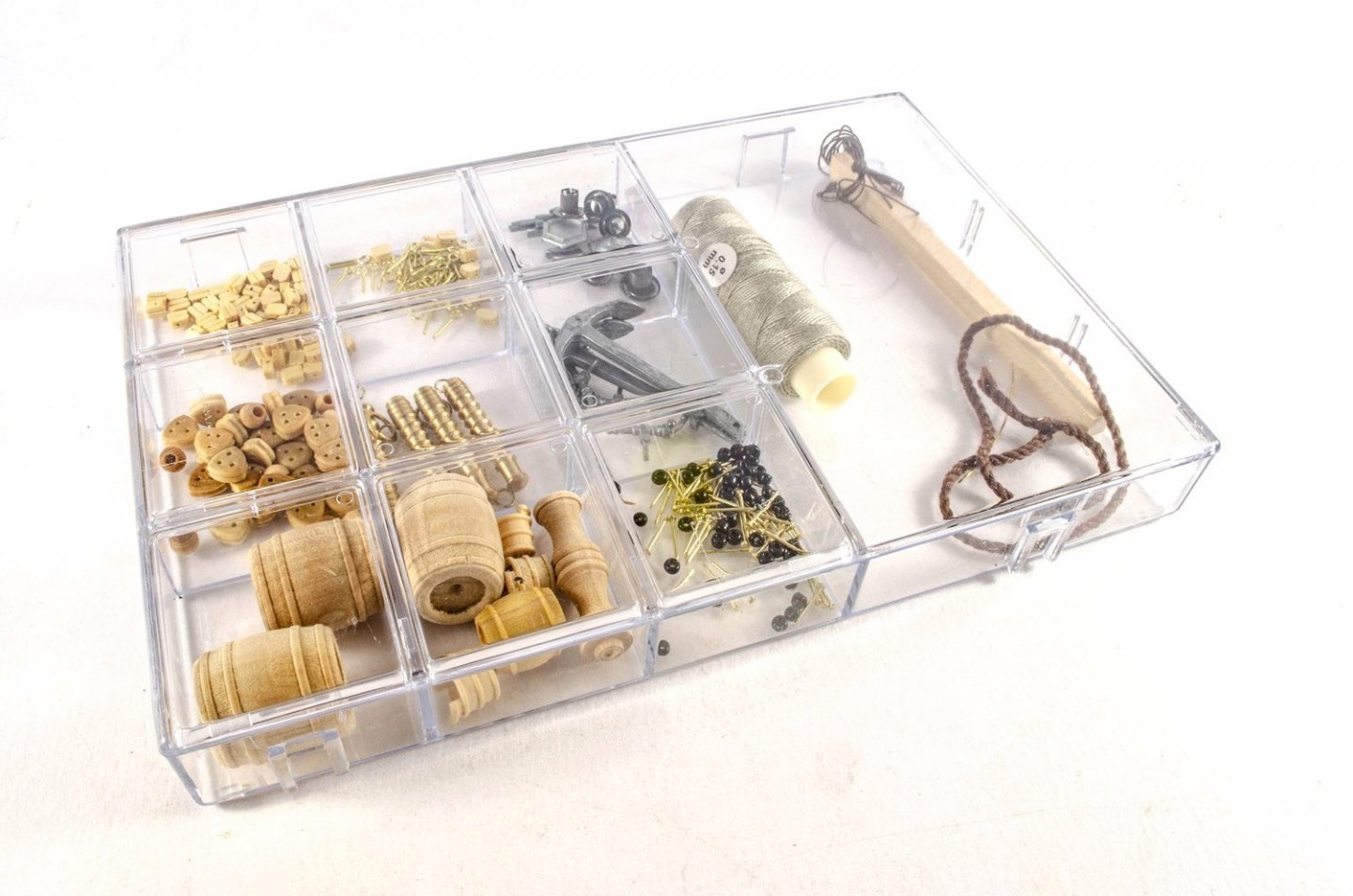
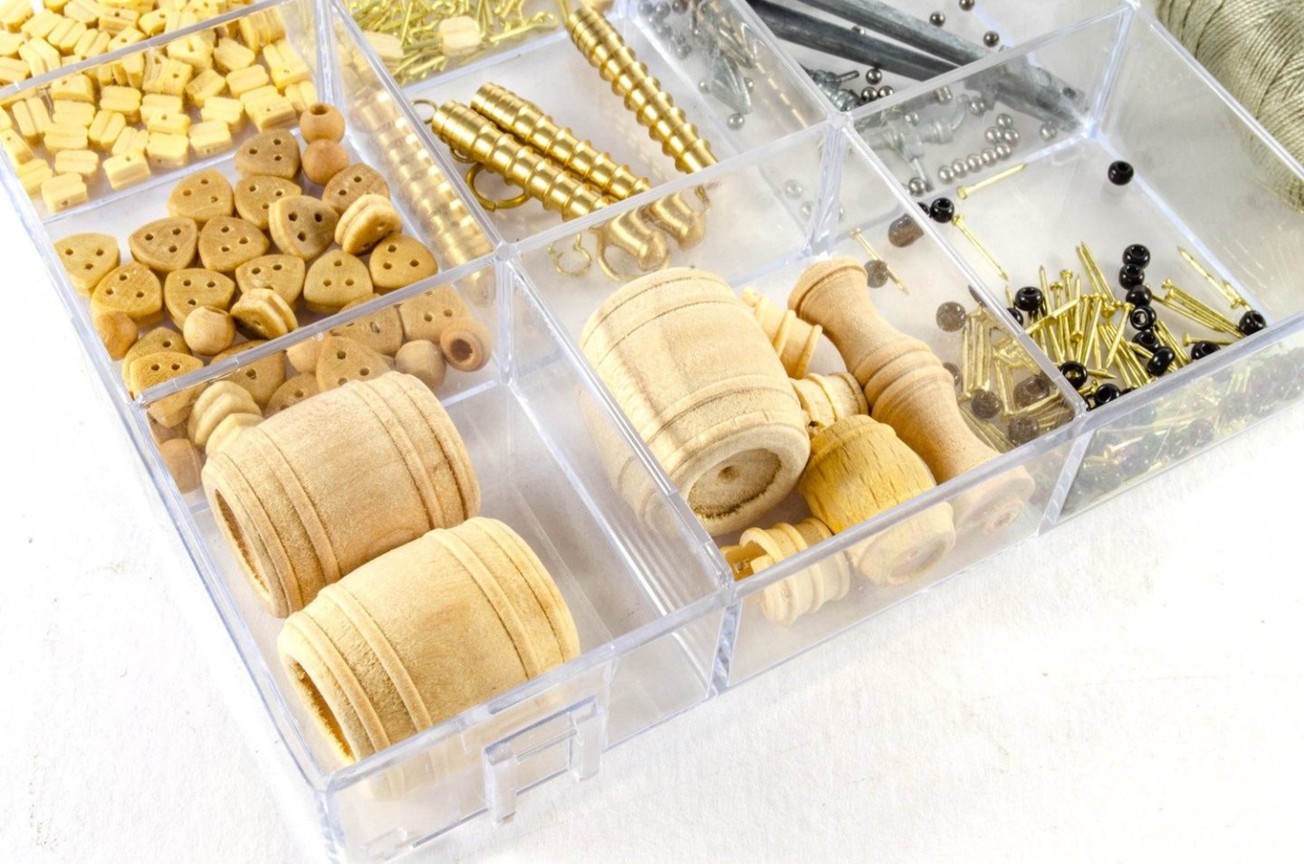
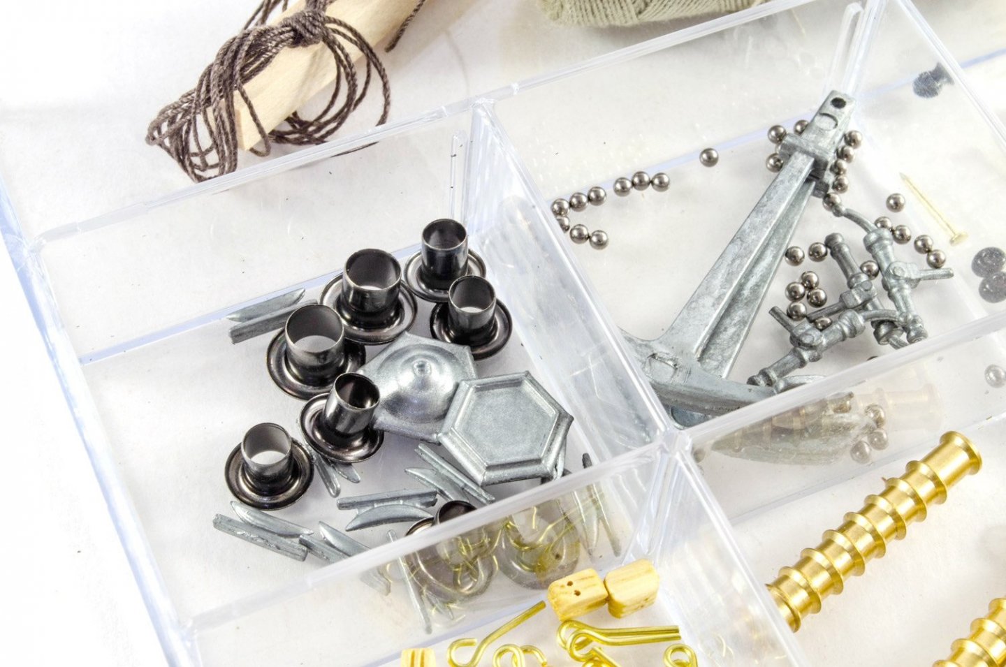
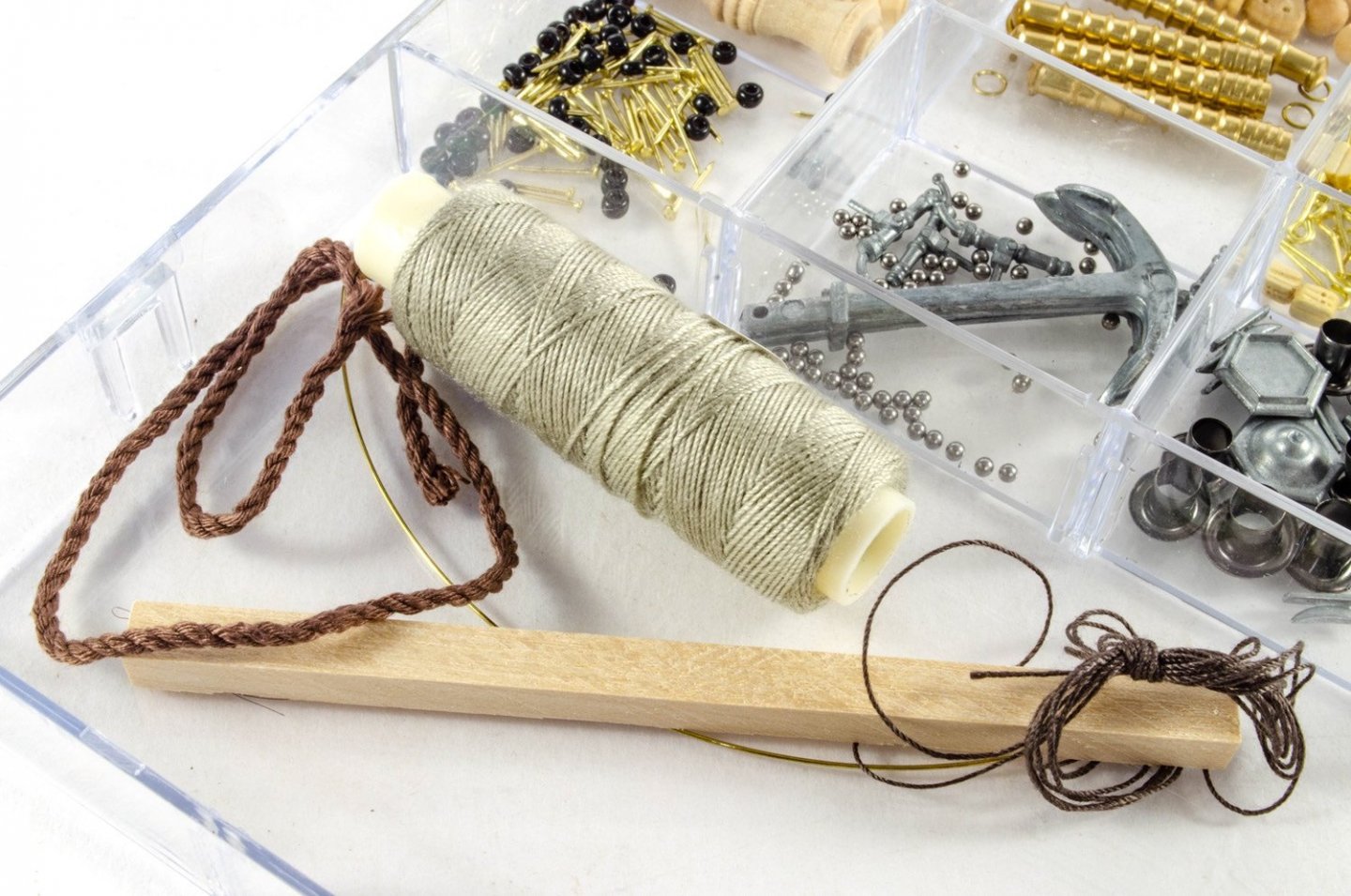
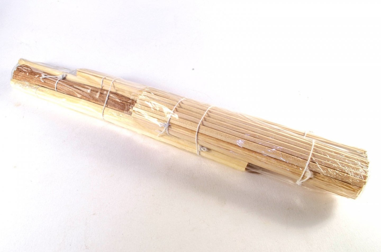
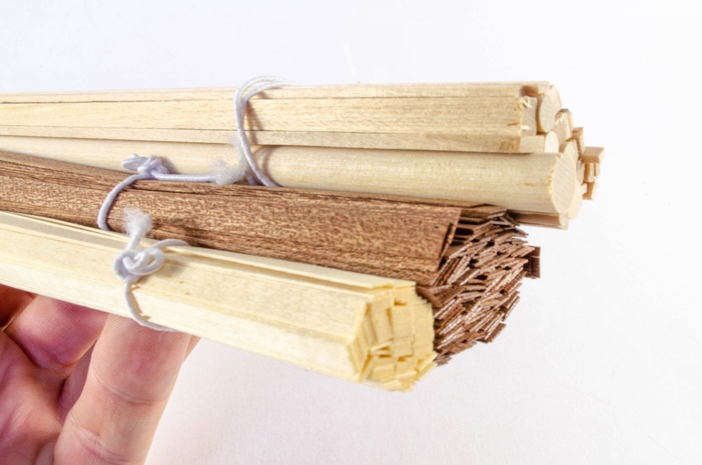
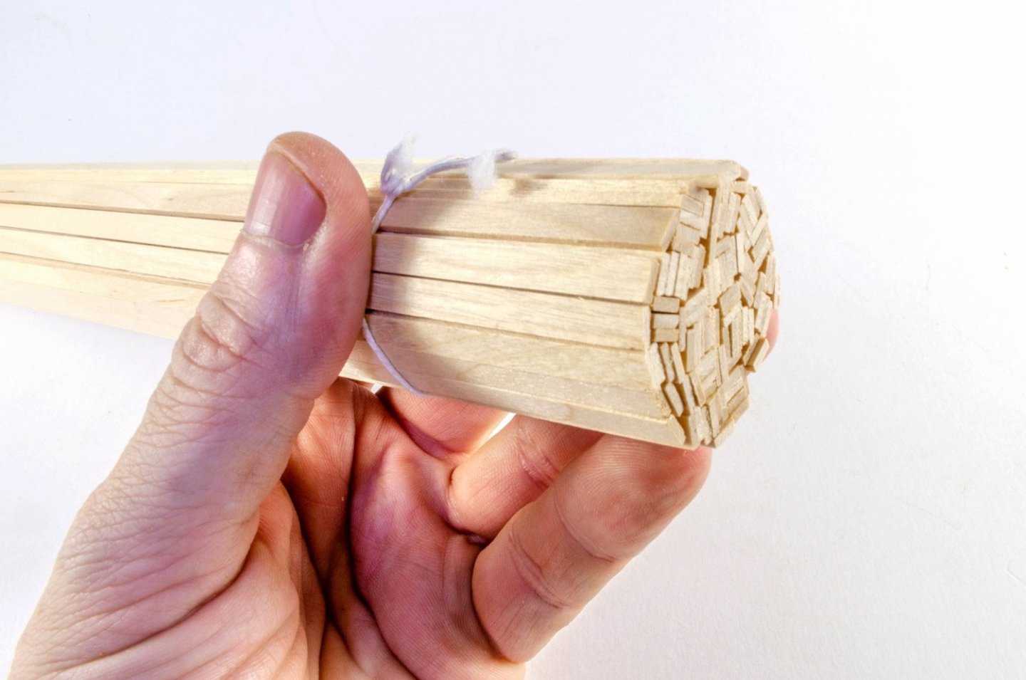
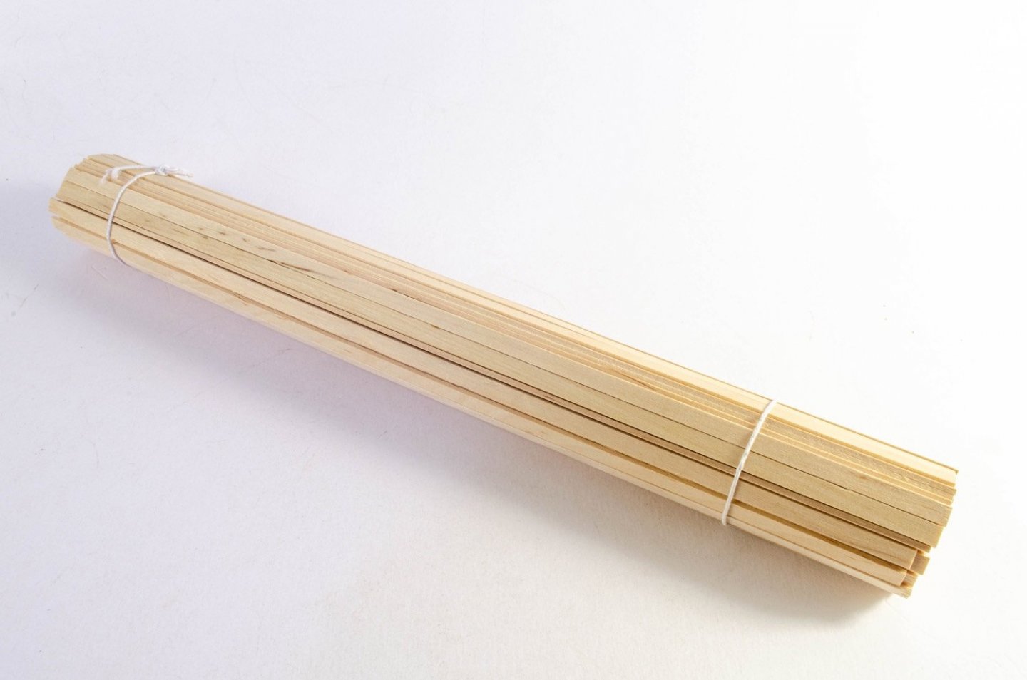
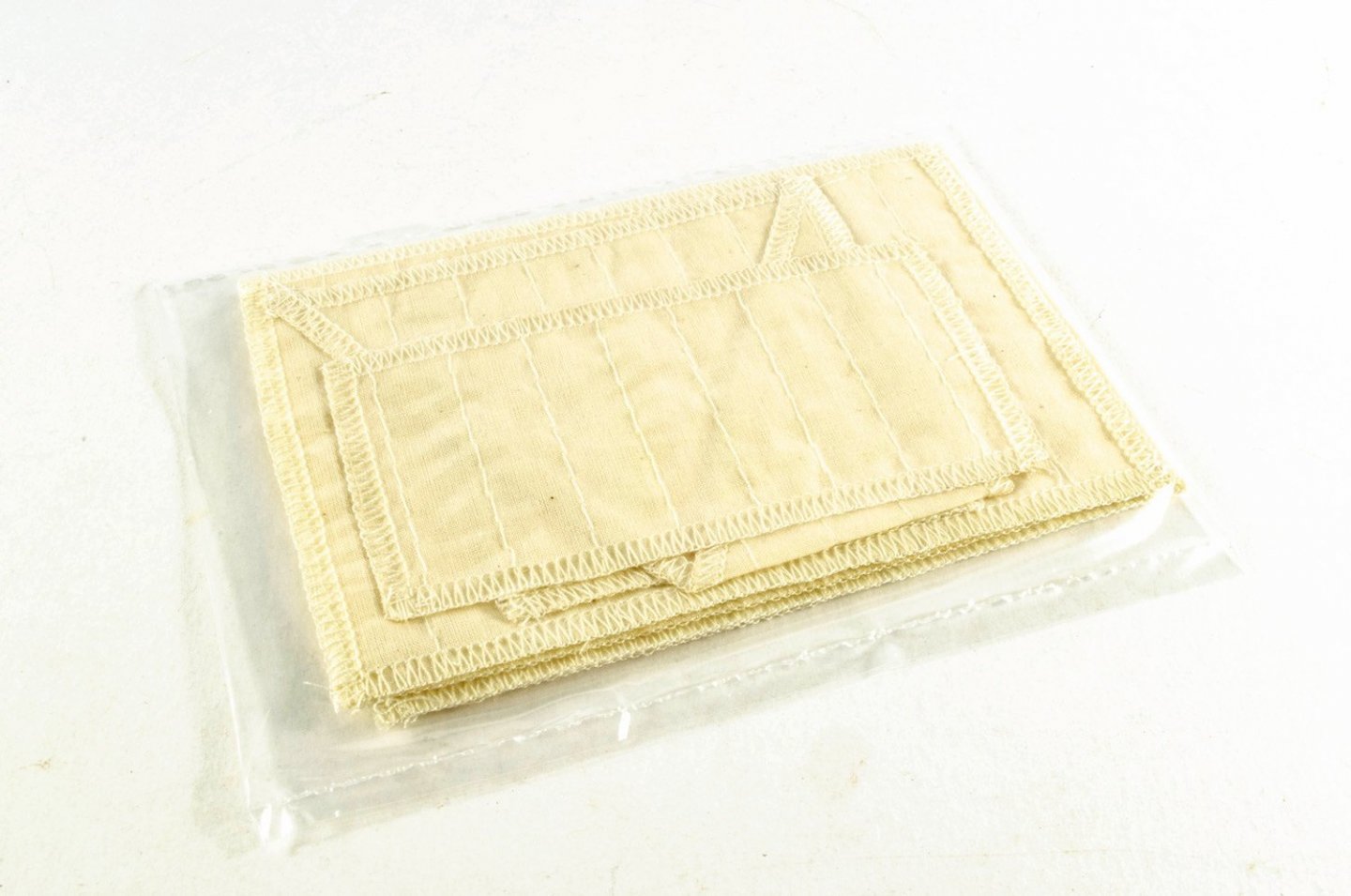
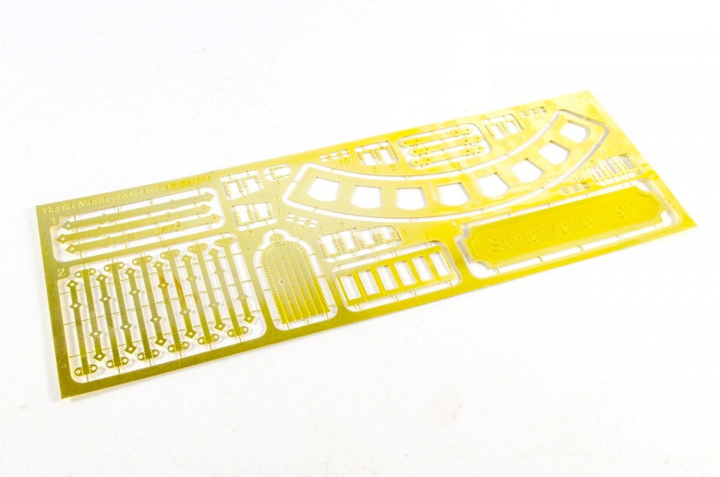
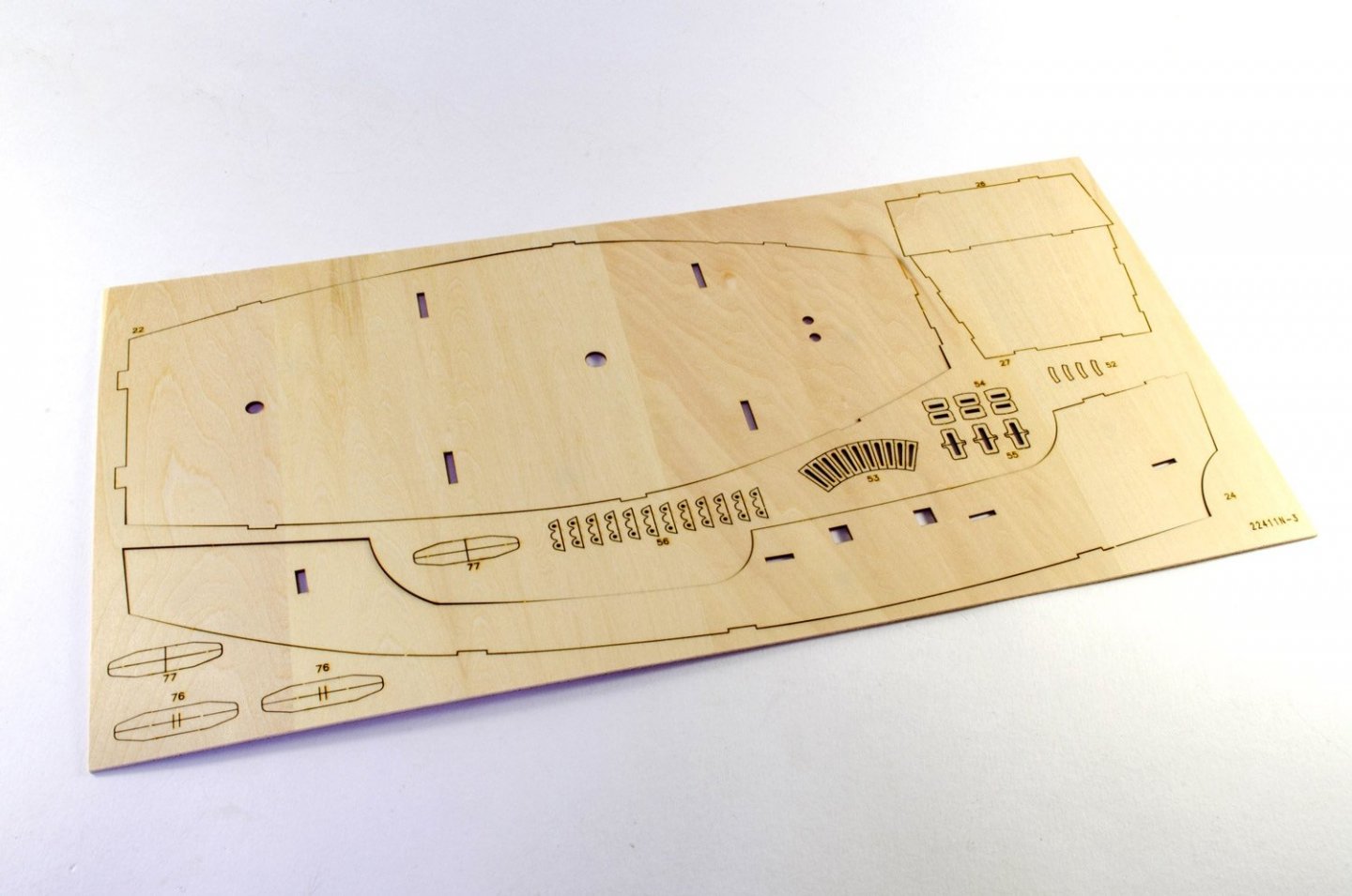
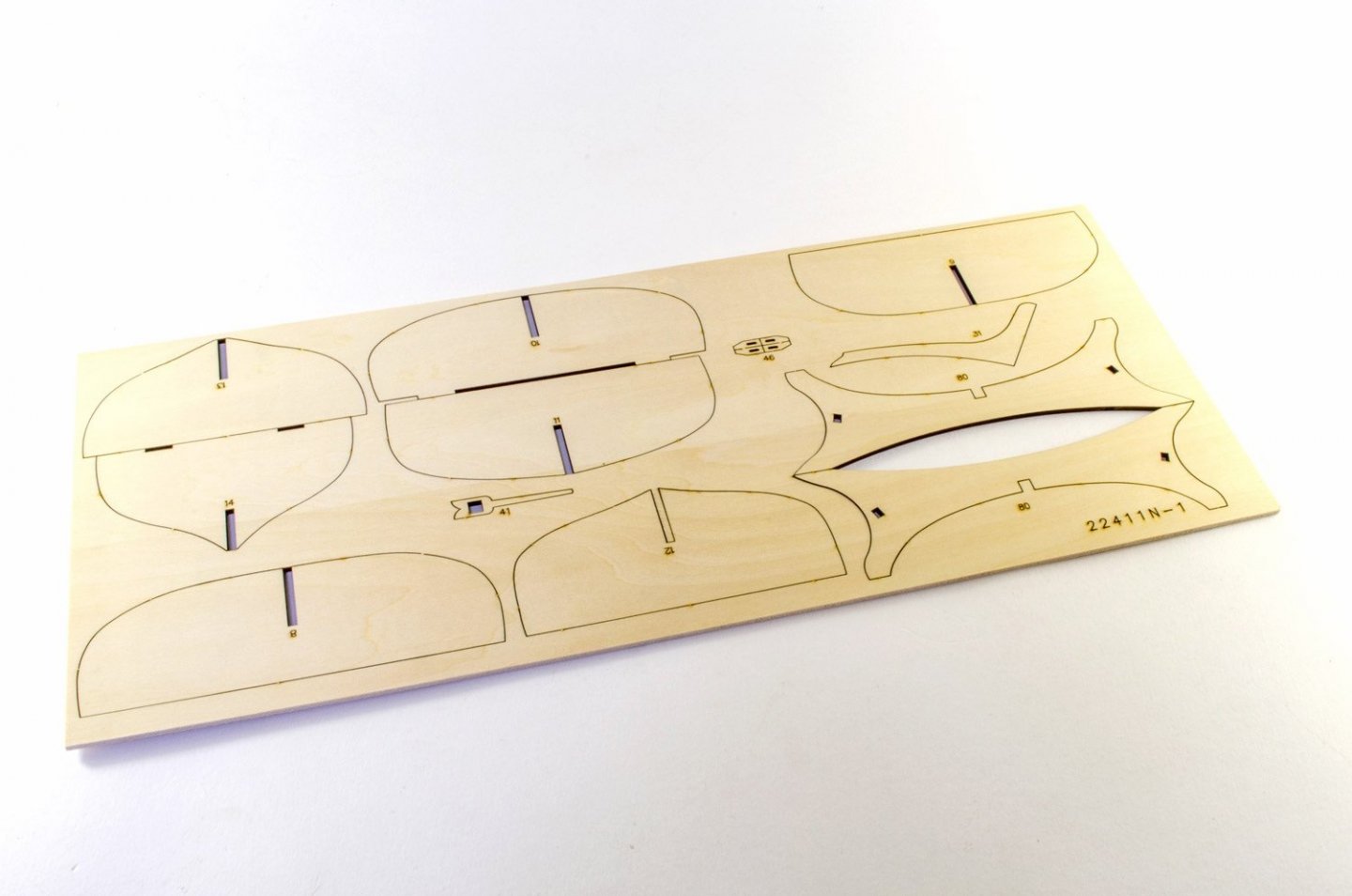
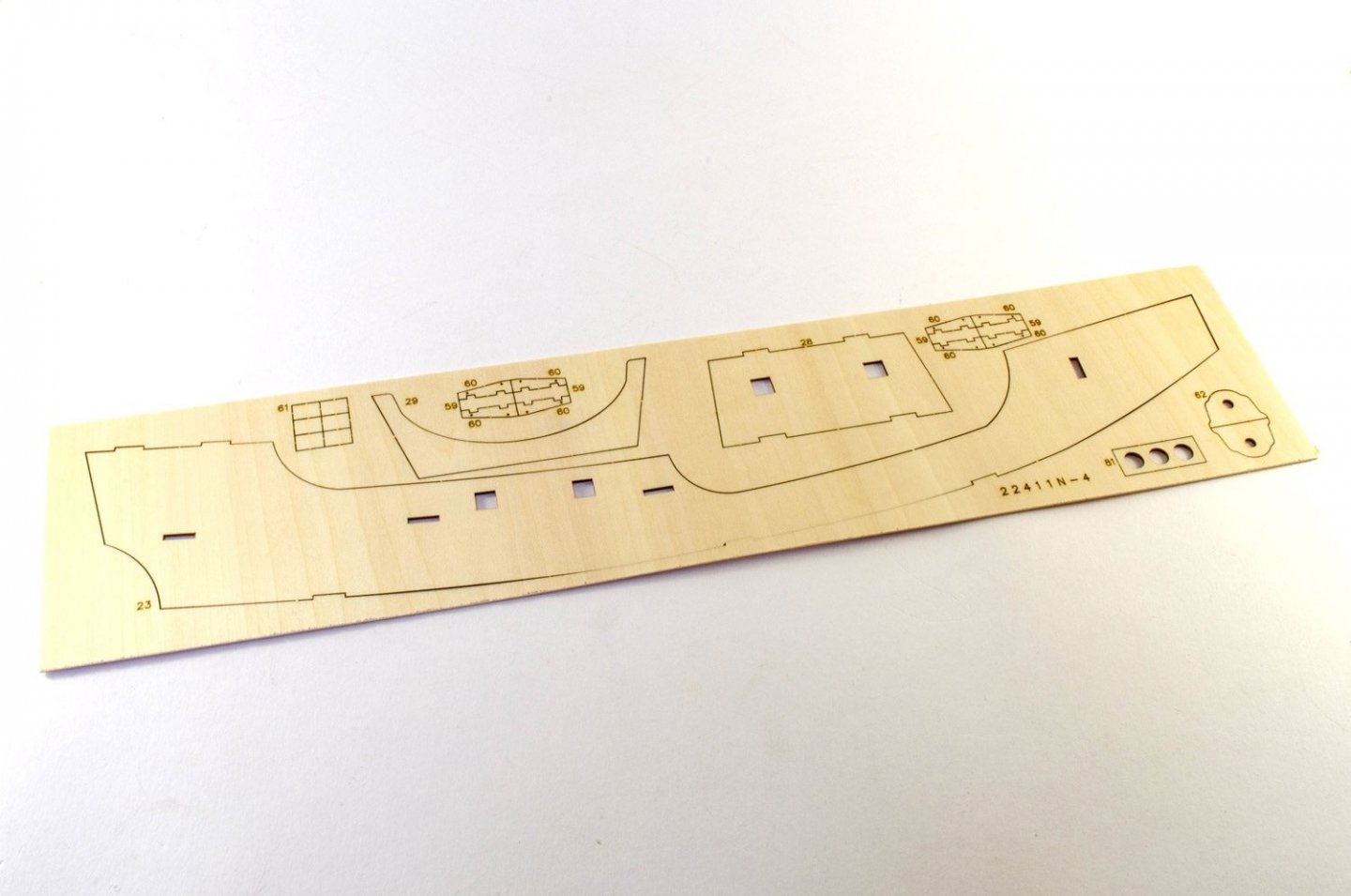
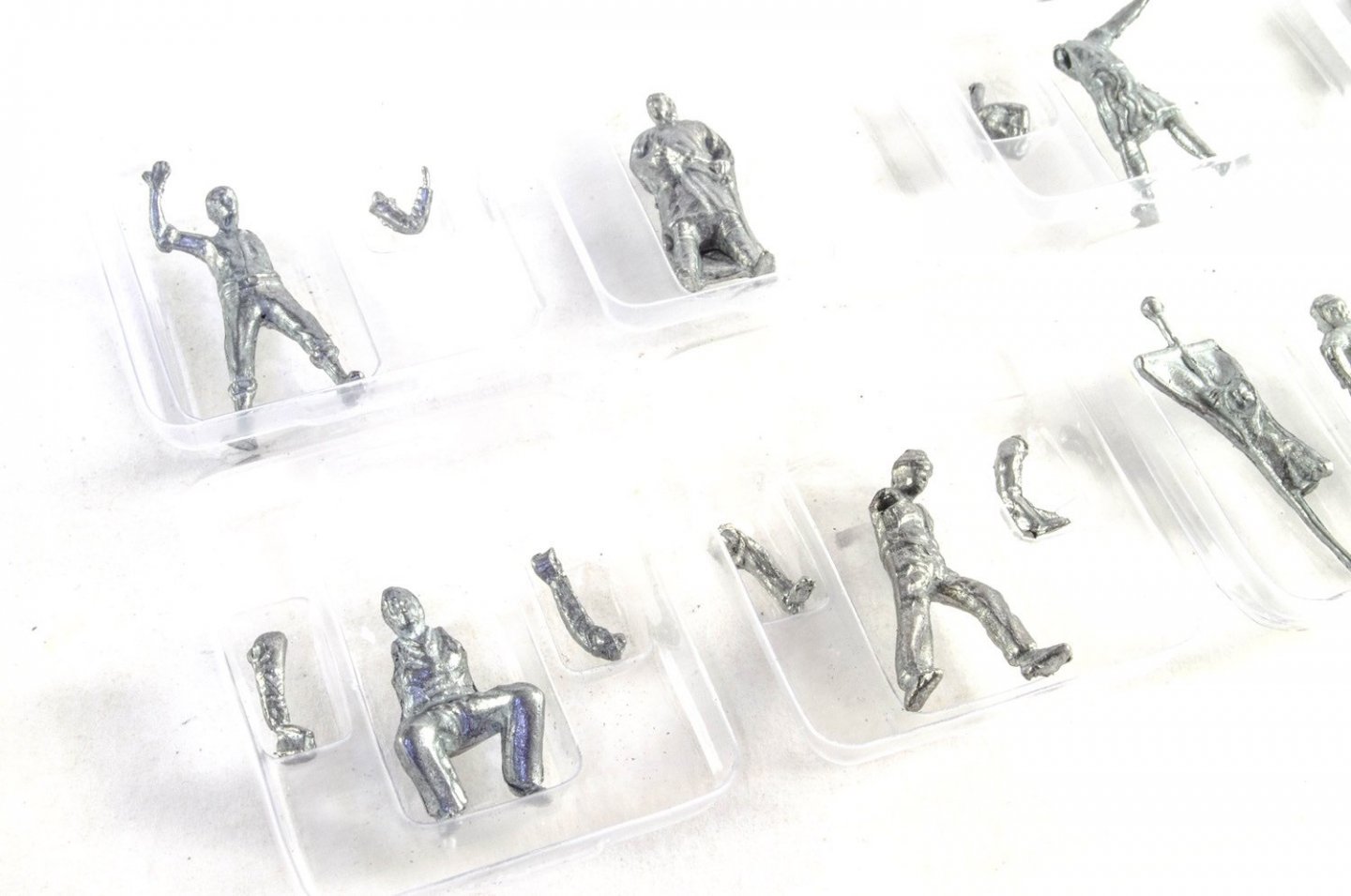
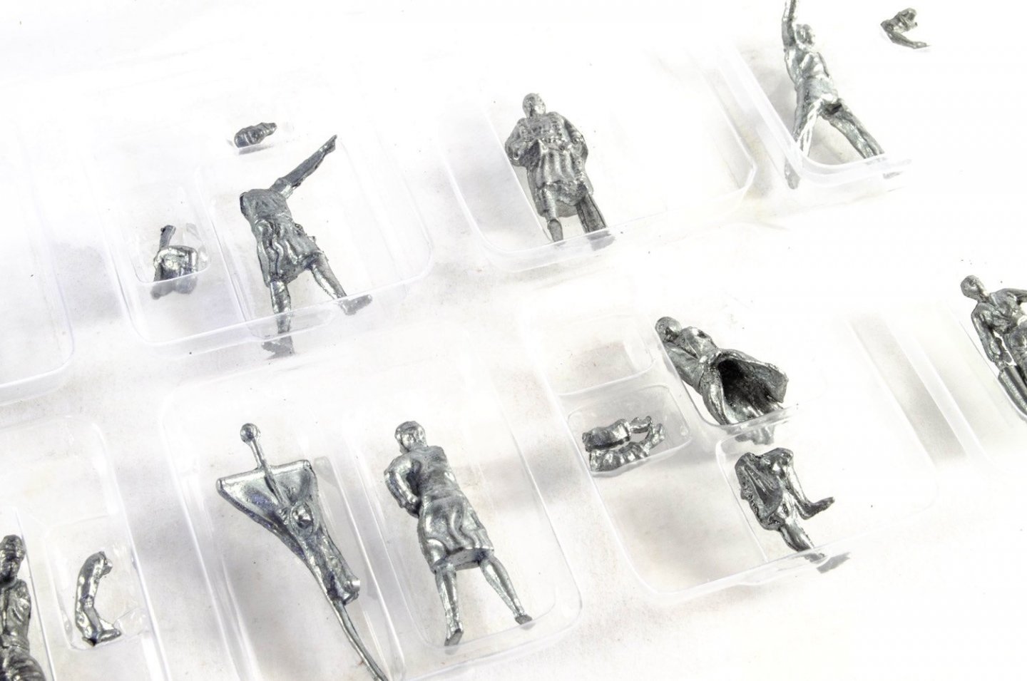
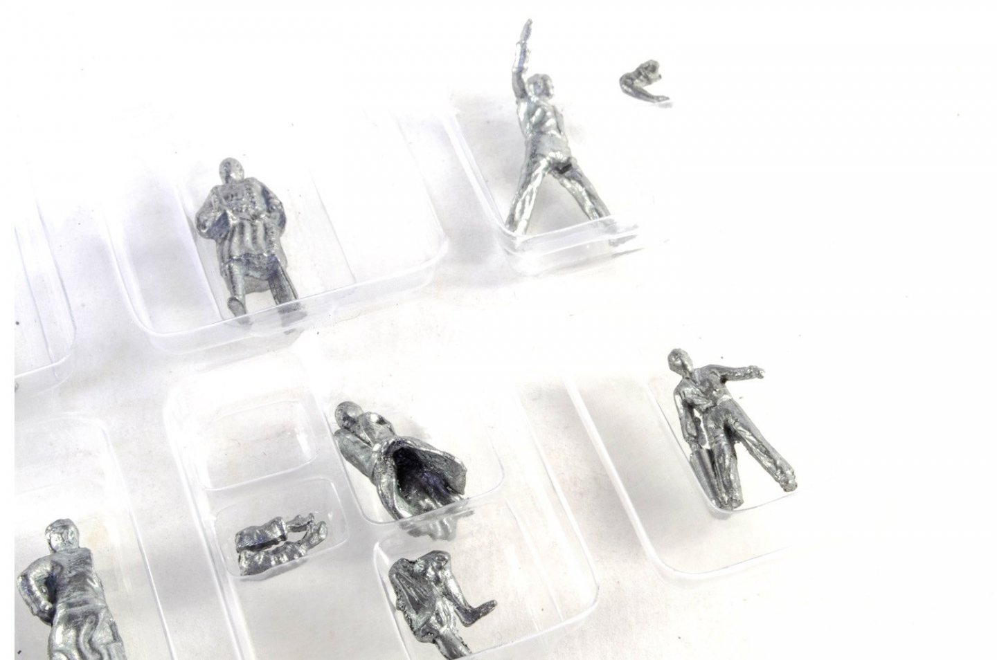
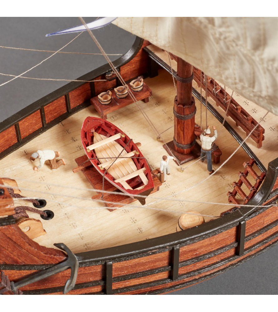
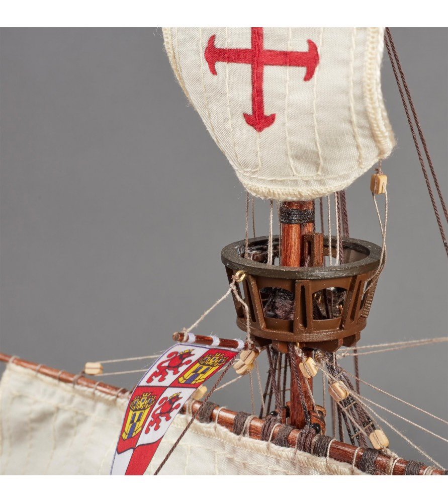
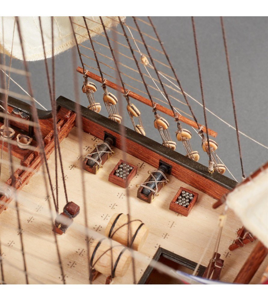
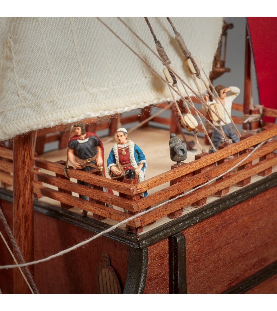
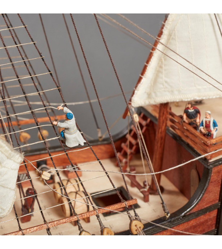
1:65 Santa Maria – 1492 Artesania Latina Catalogue # 22411N Available from Artesania Latina for €149,99 La Santa María (The Saint Mary), was the largest of the three Spanish ships used by Christopher Columbus in his first voyage across the Atlantic Ocean in 1492, the others being the Niña and the Pinta. Her master and owner was Juan de la Cosa, a man from Santoña, Cantabria, operating in south Spanish waters. Requisitioned by order of Queen Isabella and by contract with Christopher Columbus, whom de la Cosa knew previously, the Santa María became Columbus's flagship on the voyage as long as it was afloat. Having gone aground on Christmas Day, 1492, on the shores of Haiti, through inexperience of the helmsman, it was partially dismantled to obtain timbers for Fort Navidad, "Christmas Fort," placed in a native Taíno village. The fort was the first Spanish settlement in the New World, which Columbus had claimed for Spain. He thus regarded the wreck as providential. The hull remained where it was, the subject of much modern wreck-hunting without successful conclusion. The kit I’ll always have an affection for Artesania Latina as those were the kits that started me in this hobby, and I built a small number of them before moving onto things like Panart, Model Shipways, Amati, and the sort of projects I’m building now. In fact, my first ever kit was their San Francisco, bought from a shop in York. Although there are of course other very fine entry points into the hobby for the raw beginner, there is obviously still a real place in that market for AL, who seemingly came back from collapse in the recent past. The re-emergence of AL kits has also seen then getting a revamp in terms of some materials, packaging and instructions. I’ll come to the latter, later in the review. AL’s original Santa Maria was first released in 1992, and now we see a ‘revitalised’ kit. The new release is packaged into a much different style of box than I’m used to seeing with Artesania, with it still being a rigid and glossy affair with many images of the finished vessel. Inside the box, the contents are packed a little differently too, and not quite as tight as they used to be, with some space for things to rattle around a little. All strip and dowel is packaged into bundles tied with elastic cord and shrink-wrapped, whilst the sheets of parts are presented in a tough shrink-wrap film. Also included in the kit are the pre-stitched sails and some masks to paint the crosses onto them, a sheet of photo-etch parts, flags, a plastic storage box containing all the fittings, and an instruction manual on DVD. Why a DVD? I think it’s more to do than with me being a traditionalist, the reason why I am not a fan of manuals on a DVD. The only place I can see these is on a screen, and I won’t take my MacBook into a dusty workshop while I work on a project. To me, there is no substitute for an actual paper copy to work from. This model has no plans either…absolutely everything is done from the images on the DVD. Don’t get me wrong, Artesania have done an incredible job of showing every stage, including rigging, in photographic form, but unless I print this out, then I will need to keep referring to a computer. I suppose it’s understandable that they won’t want to supply one though, as the manual is a hefty 164 pages long! All done in the most brilliantly pictorial fashion. There is also another 12-page manual showing every single sheet of material and strip of wood, fitting etc. in high resolution. In all, the DVD contains the manuals in both PDF and JPG format. As well as those, six videos are also included which show a few tips and how to use some of the tools that you might want to purchase. Generally, I have to say that I would prefer the older style instructions AL used to supply, along with plans. Timber! The ship’s hull is built up from 3mm ply, which is all cleanly cut, with part numbers engraved on there too. On the false keel, all bulkhead positions are also engraved with the bulkhead number which slots into there. That’s all easy enough. Also included on the 3mm ply sheets are parts for making the cradle for the kit, shown on the box as a ‘bonus’. In all fairness, the original release of this kit didn’t have a cradle for build/display, so that’s fair enough. The deck sections are supplied in a combination of both 1.5mm and 2mm ply. There is no camber in the decks on this kit. It’s perfectly flat across its breadth. The 2mm sheet also carries parts for the jig used to build up the ship’s boat. I’ve definitely seen that approach to ship’s boats featured by another manufacturer somewhere (!) It is a big improvement over Artesania’s original practice of including poorly cast boats in their kits. Also found on the 2mm sheet are parts for the mast top. Also in 1.5mm ply are the hull sides/bulwarks, extending from their lowest point on the main deck, up to the very top of the forecastle and poop deck bulwarks. The ply used on this kit is verry reminiscent of the stuff I used on the Artesania kits I built all those years ago, but maybe a higher quality than it was back then. Other parts are supplied on 1.5mm sheet. The ply itself is of a very reasonable quality, and definitely a step up from the AL kits I built when I started in the hobby, although there is still warping present, perhaps exacerbated by tightly shrink wrapping the sheets up with parts. Strip timber is verry reasonable in quality and it’s of a nice consistency. As the strip material is also coded, you can clearly identify this with the parts plan which has images of the various material types and thicknesses. Photo-etch One fret of photo-etched parts is included in this kit, containing the stand nameplate, cabin door, inside edge of mast top, lantern body etc. Production quality is very good and generally on par with like materials I’ve seen in some other kits. Fittings All fittings are supplied in the same style plastic compartment box that I remember when I first bought AL kits. Many of the parts in here are generic, but the quality of them seems to be perfectly fine. You’ll find eyebolts, turned brass cannon, cast anchor, swivel guns, cleats etc. as well as turned wooden windlass, barrels etc. I have to say the larger barrel size looks unfeasibly large for this scale. Other wooden items include buckets, parrel beads, deadeyes and riggings blocks. Flags, rig, sails and masks The included flags are nicely printed and come as either foldable or parts assembled from a front and back. Flag parts will need to be cut out of their master sheet. Rigging cord is of a verry reasonable quality and certainly better than I remember it being in the old days where it was full of fuzz. I mean, it’s not Gutermann, but certainly better than I remember. Five pre-sewn sails are supplied with this model, and they already have a nicely aged effect to them. Of course, one thing this ship was famous for was the large cross on the sails. This is something you will need to paint onto the sails, and thankfully, Artesania has supplied some cardboard templates to help you with that task. Instructions The Santa Maria is actually a very simple model to build and follows many of the conventions and techniques that I remember were prevalent when I began in this hobby. The breakdown of the model is quite straightforward and is depicted admirably throughout the 164 pages of the manual. There really is nothing left to any doubt with the sheet number of photos suppled, showing the various steps from so many different angles. The photos are superbly clear and will guide a builder like as if virtually holding their hand. I have to say the method of planking the hull is certainly bizarre! As this model comes with no plans, the instructions also come with a step-by-step to adding every single rigging lime on the model, and all off it is very, very clear. Conclusion I do have a lot of affection for Artesania Latina. As I’ve said before, if it wasn’t for their San Francisco, I may never have made the step into this hobby. There is quite a different feel to the actual product now, but with most familiarities remaining. There has been an improvement of sorts in the overall quality of things, or that’s certainly the way it feels/appears to me. A big change has been the instructions and their format. I’m not sure about the price point for this kit. On one hand, it seems a little high, but then again, I suppose if you even that among the number of hours it’ll take to build, it’s still a relatively cheap hobby. Definitely a nice build for a beginner. My sincere thanks to Artesania Latina for supplying this kit for review on Model Ship World. I do think it’s nice to see their name back in the hobby after that short break. To purchase directly, click the link at the top of this article. …lastly: Set of 10 x 1:65 Metal Figurines for Caravels and Galleons Catalogue # 22411F Available from Artesania Latina for €19,99 This is a set of white metal figures designed to be used with kits such as this, especially as Christopher Columbus himself makes a guest appearance in the line up! The figures are listed as: Christopher Columbus. Juan de la Cosa. Martín Alonso Pinzón. Vicente Yáñez Pinzón. Rodrigo de Triana. Sailors 1, 2, 3, 4, and 5 I have to presume a couple of the sailors are boys as they do seem to be smaller than the other protagonists. Metal casting is quite nice and these should paint up nicely with the prerequisite skills. Various poses are included so you can have men climbing up rig etc. The figures are supplied in a slip box and held in a plastic tray within.


-
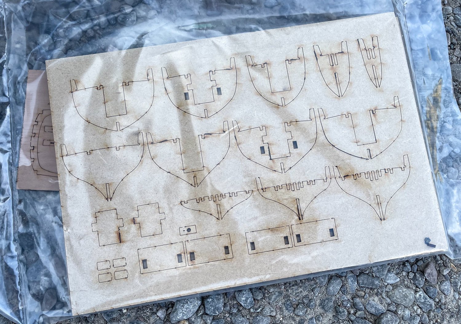
You can add a plank that runs along the bottom edge to where the keel fits, if you wish. I did it this way so you aren't planking all that deadwood area in lime, only to then sand pretty much all of it away in that area. You'll see that the lime planks sweep upwards away from the deadwood area at the lowest point. Your last plank at the keel area will cover the slots in the MDF, so there is a 'socket' for the pear keel to later fit into. A reason for not fitting the pear keel at this point is that it makes it easier for the modeller to shape the hull without obstruction or the likelihood of damage being caused to it.
-
It's around 28 degrees at moment. It has gone to mid 30s before now and with the old style, hot photography lamps adding to my misery. I really do need to change to LED and soon. I currently have bowsprit and mizzen mast built. The main mast is 3/4 built and the foremast about 1/3 done. All masts will then need their blocks and ironwork/lashings added, then painted where needed. My next proper update will show all masts in place with yards pinned in position.

- 355 replies
-
- 19
-
-
-
- vanguard models
- Sphinx
- (and 1 more)