James H
-
Posts
6,142 -
Joined
-
Last visited
Content Type
Profiles
Forums
Gallery
Events
Everything posted by James H
-
 I will when I've finished it 🤣 Here's a pic of a very old model of one of these.
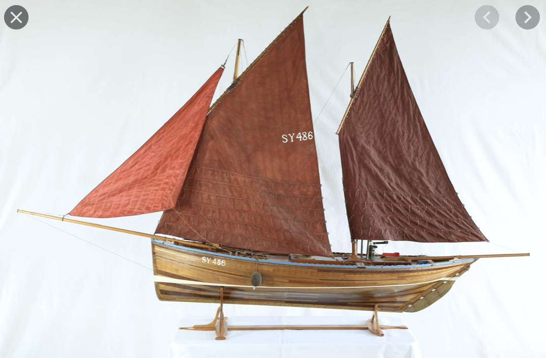
- 100 replies
-
- 12
-

-
- zulu
- vanguard models
- (and 2 more)
-
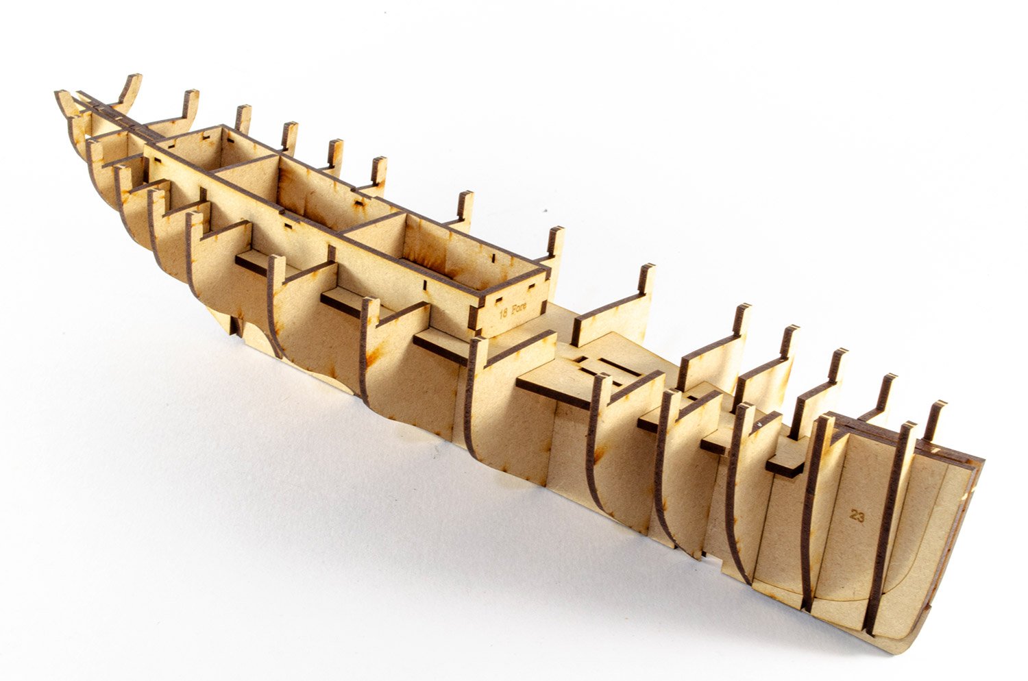
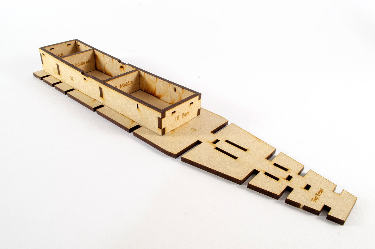
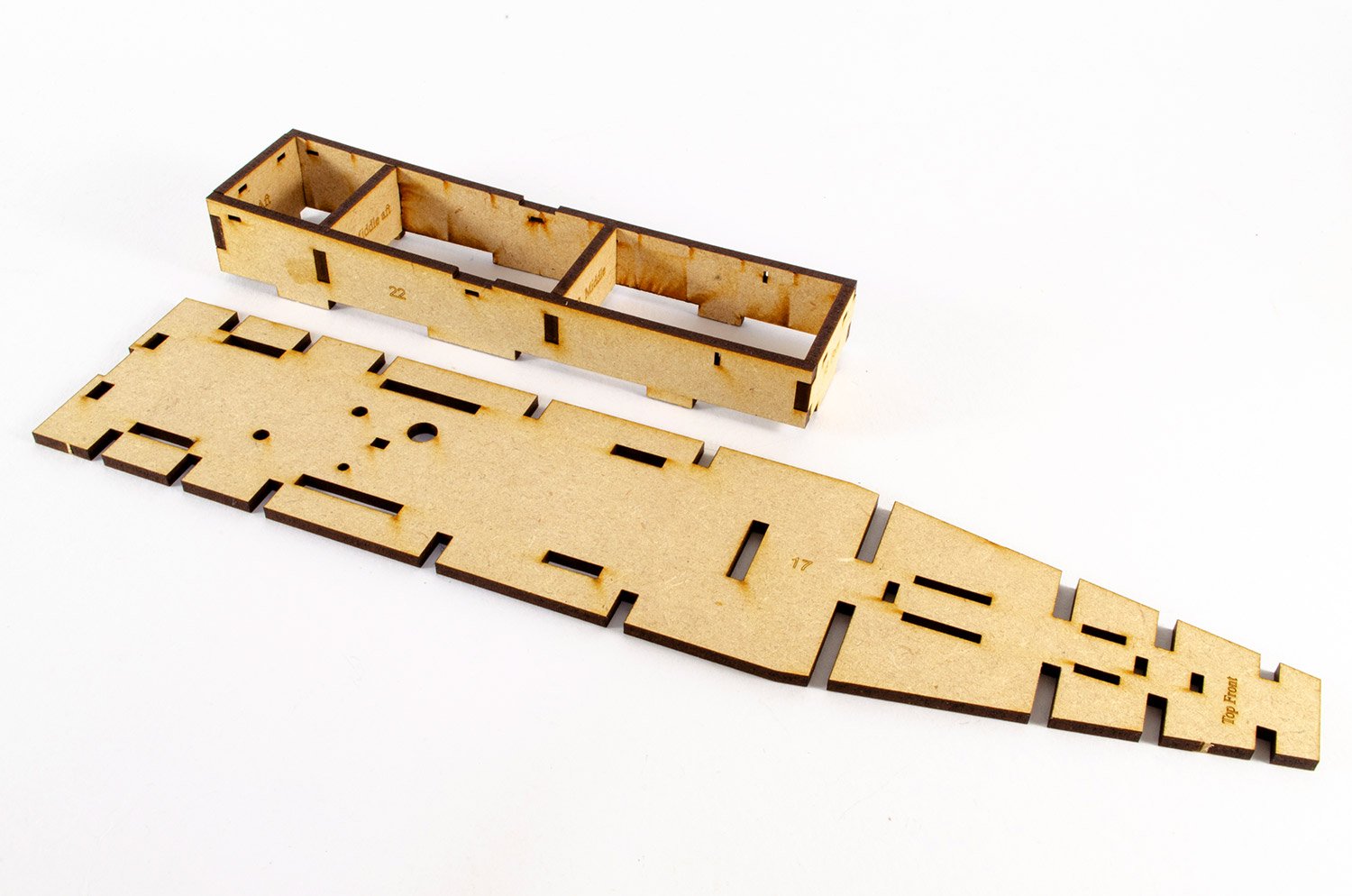
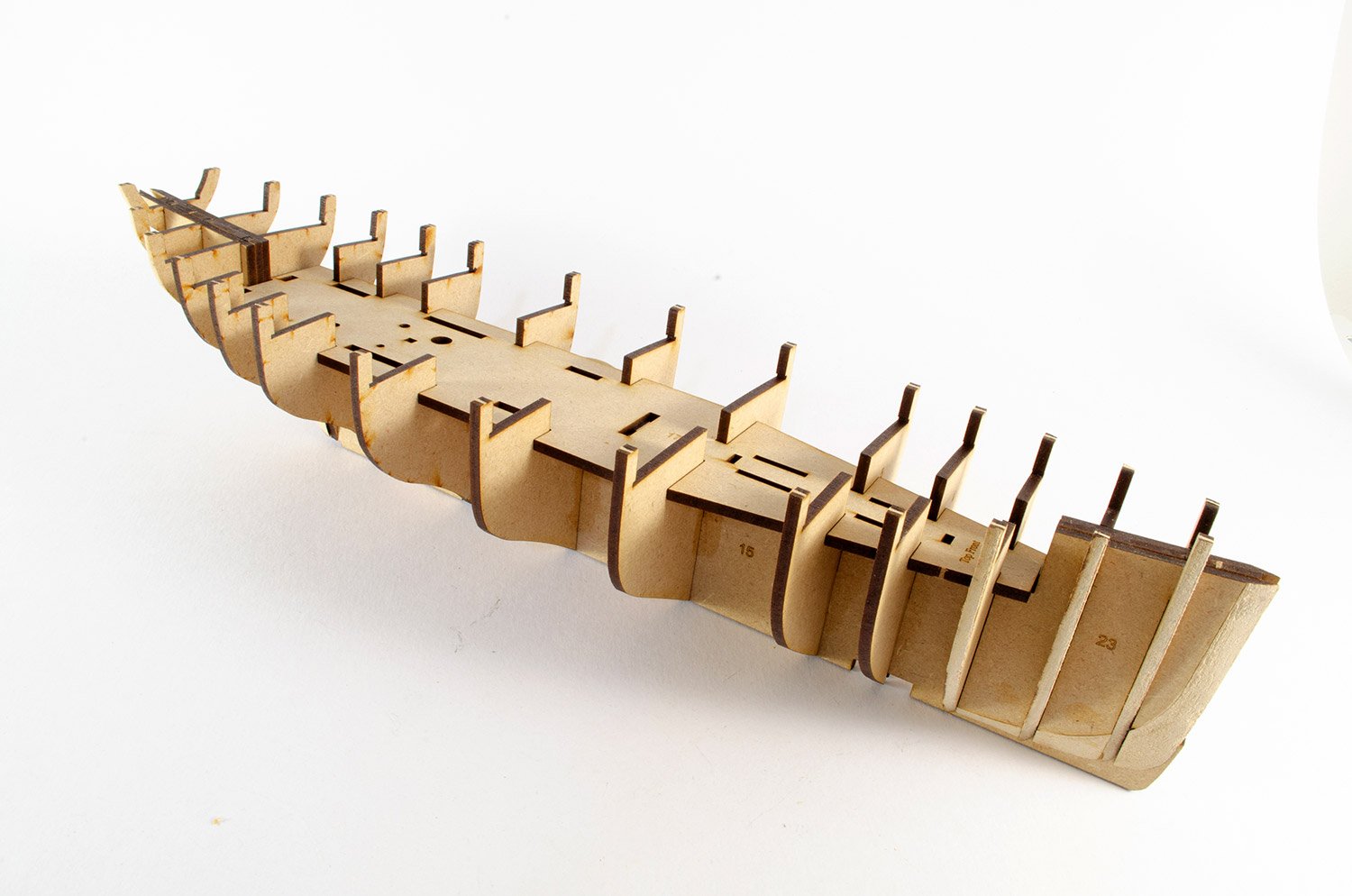
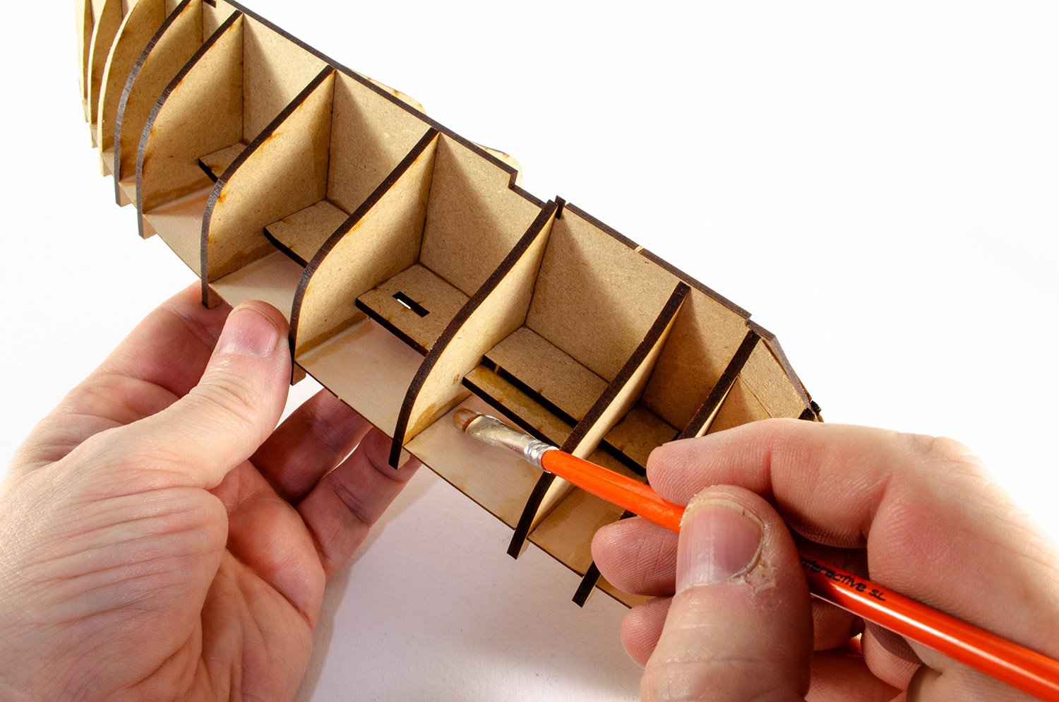
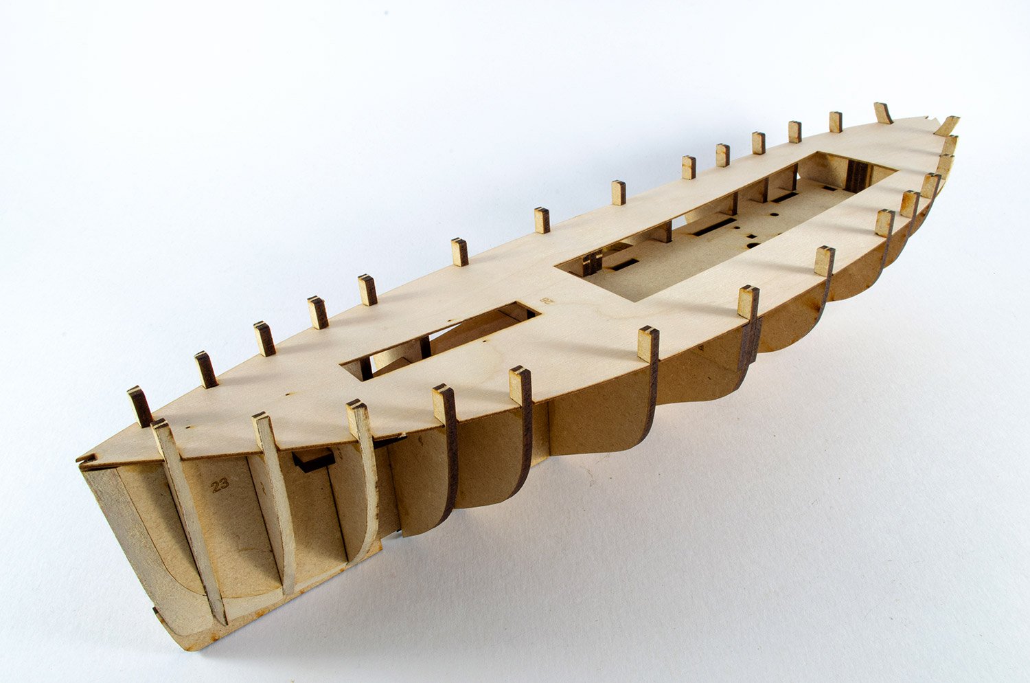
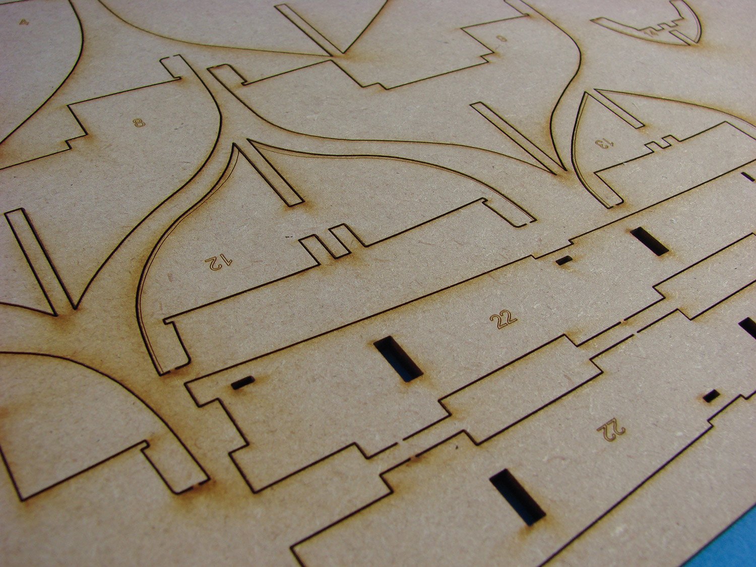
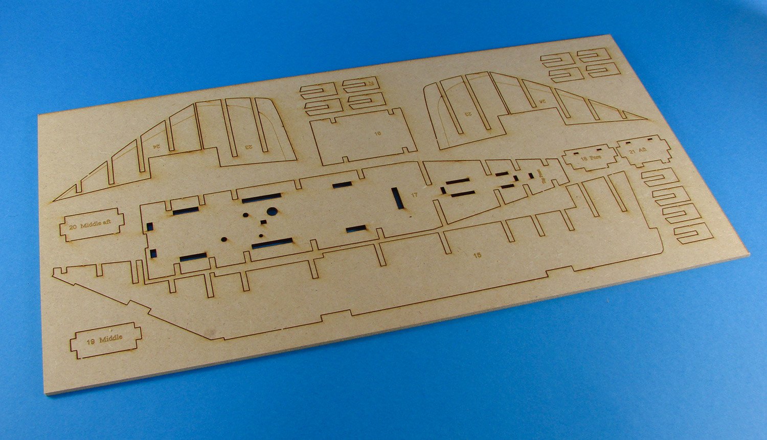
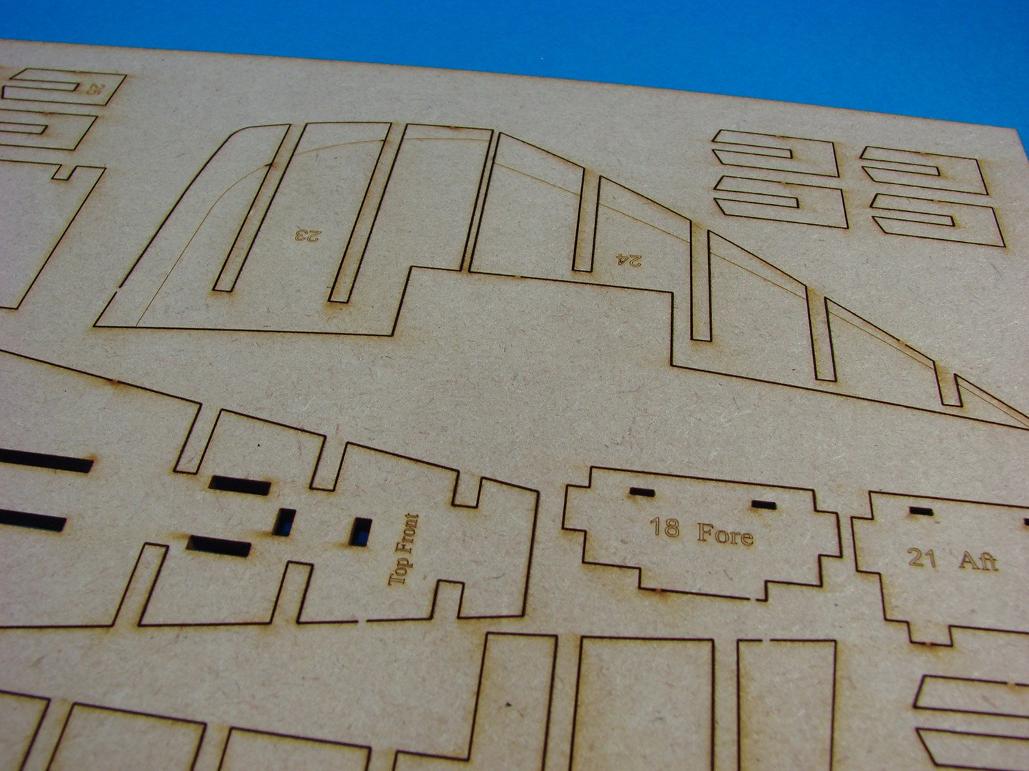
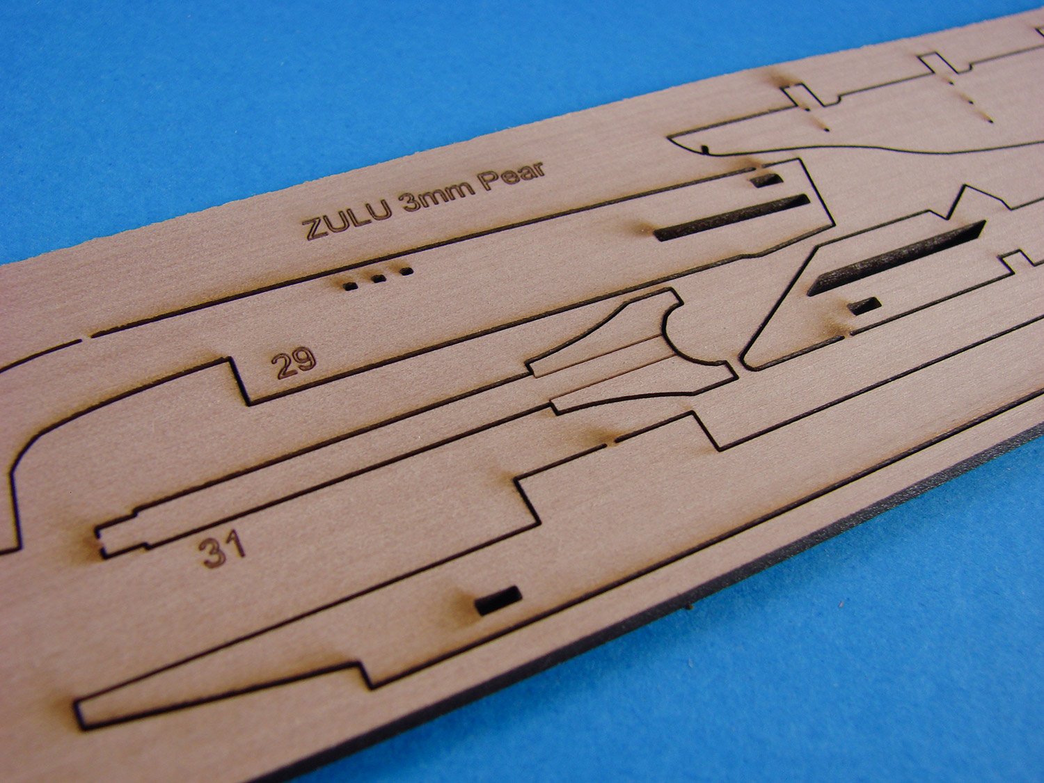
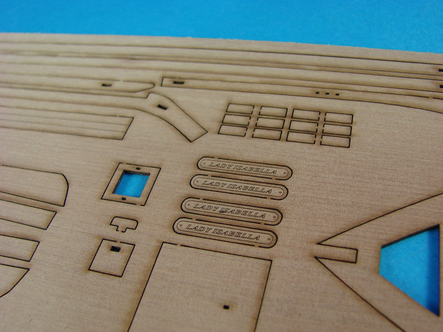
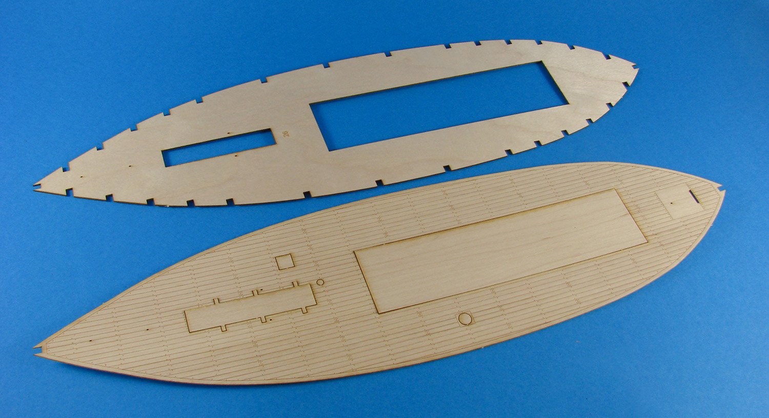
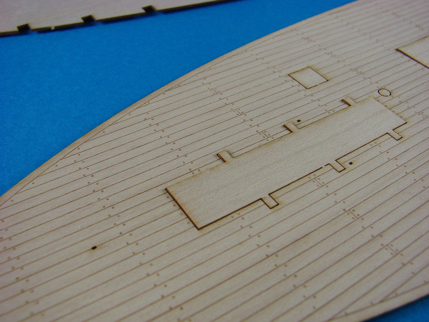
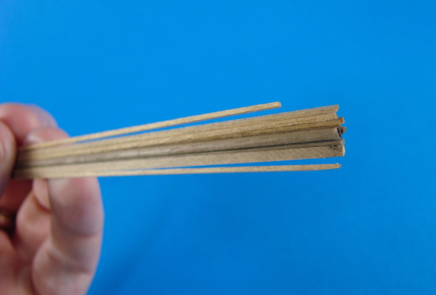
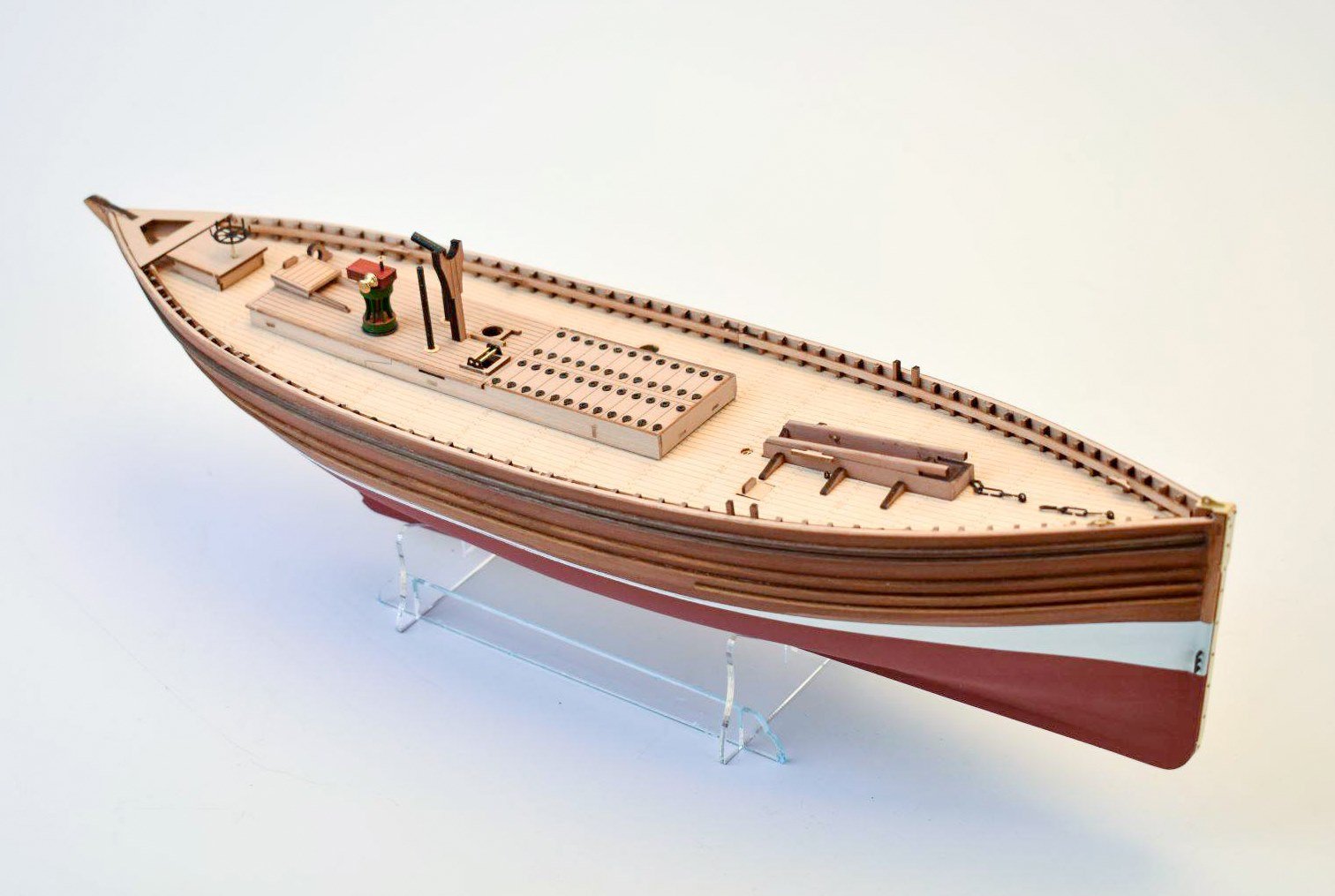
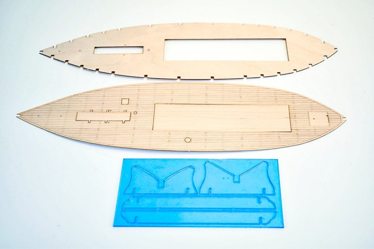
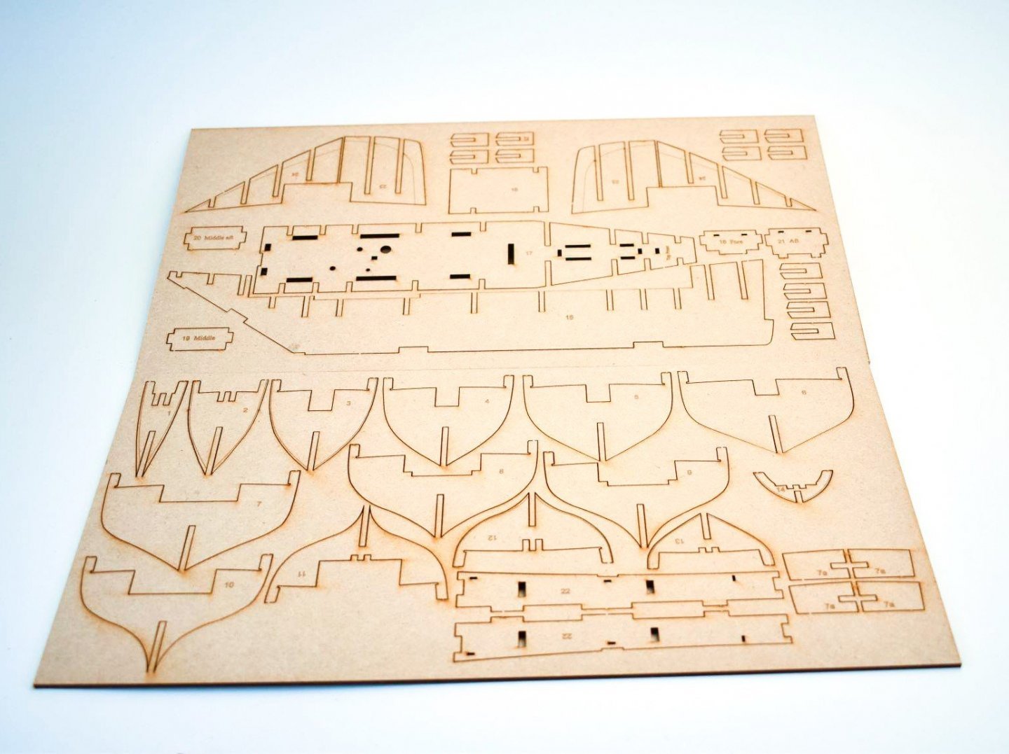
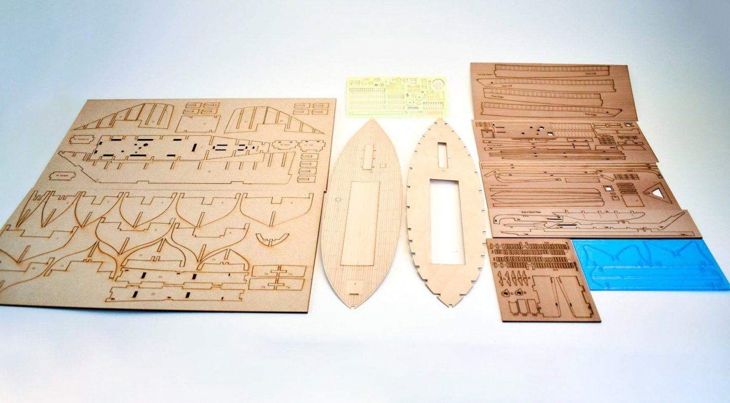
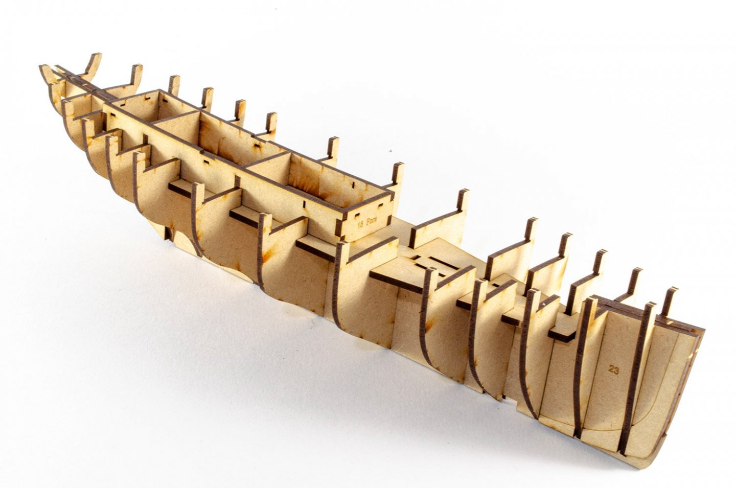
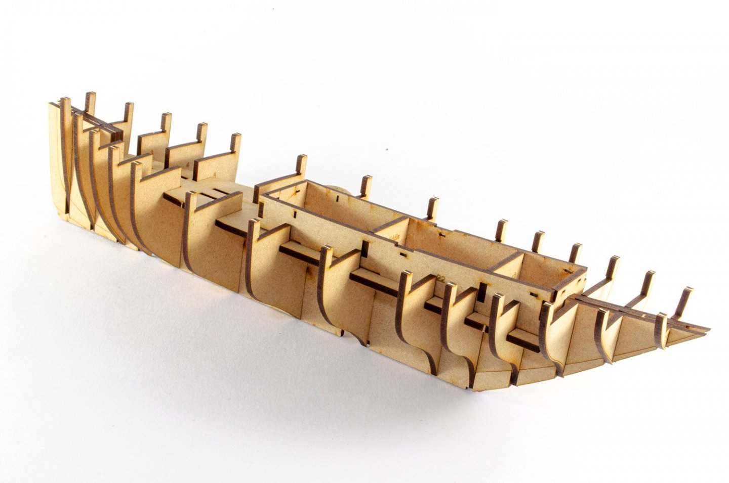
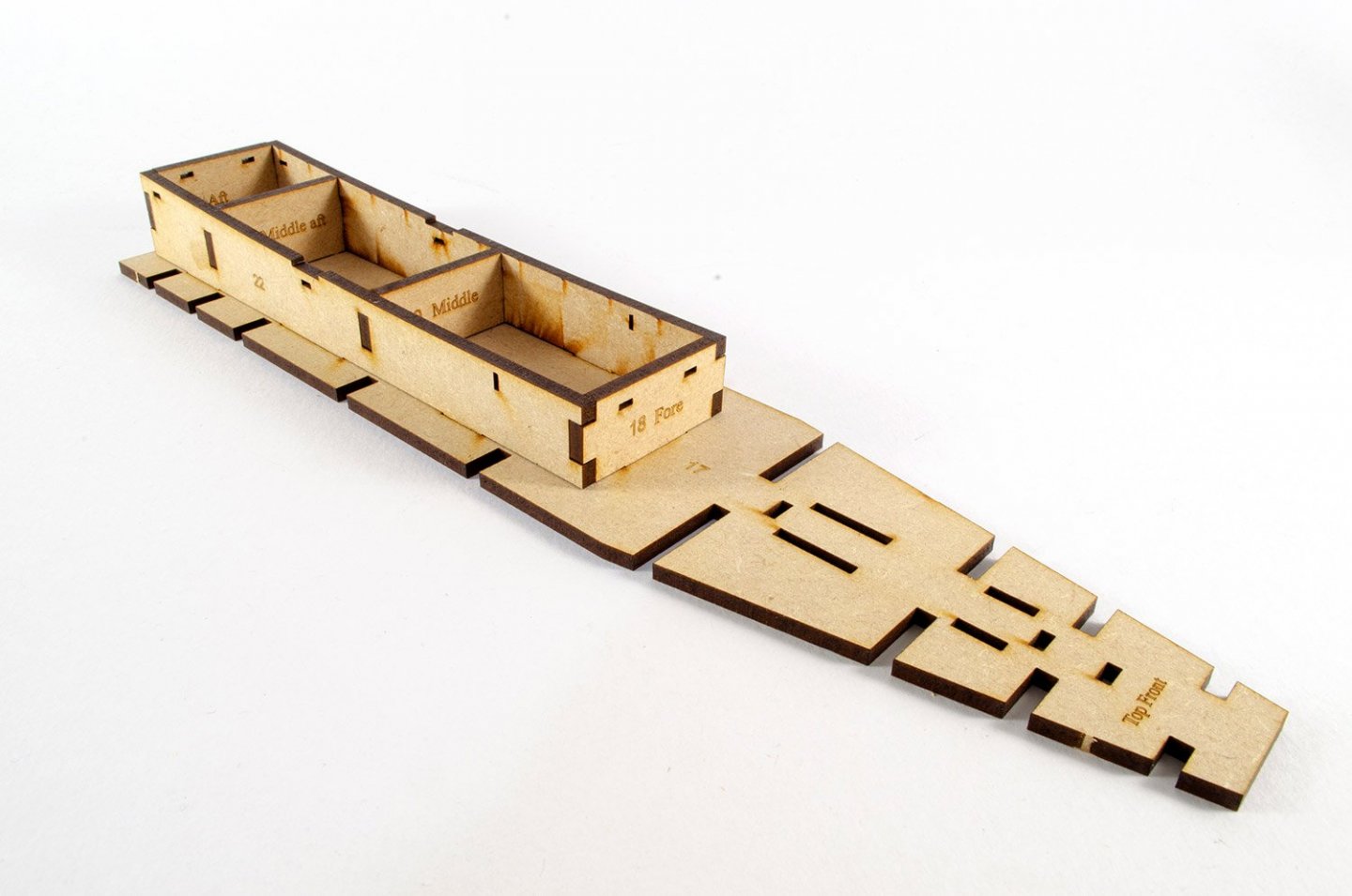
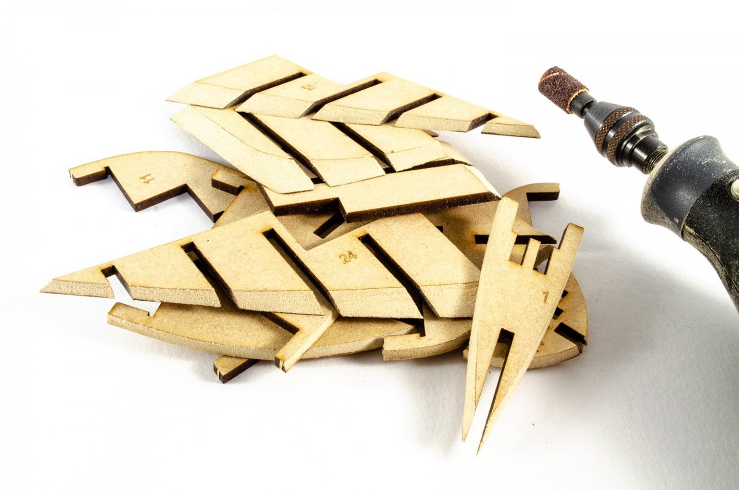
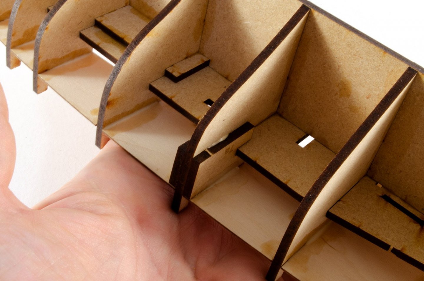
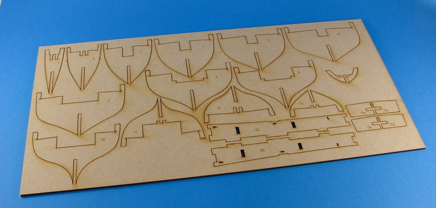
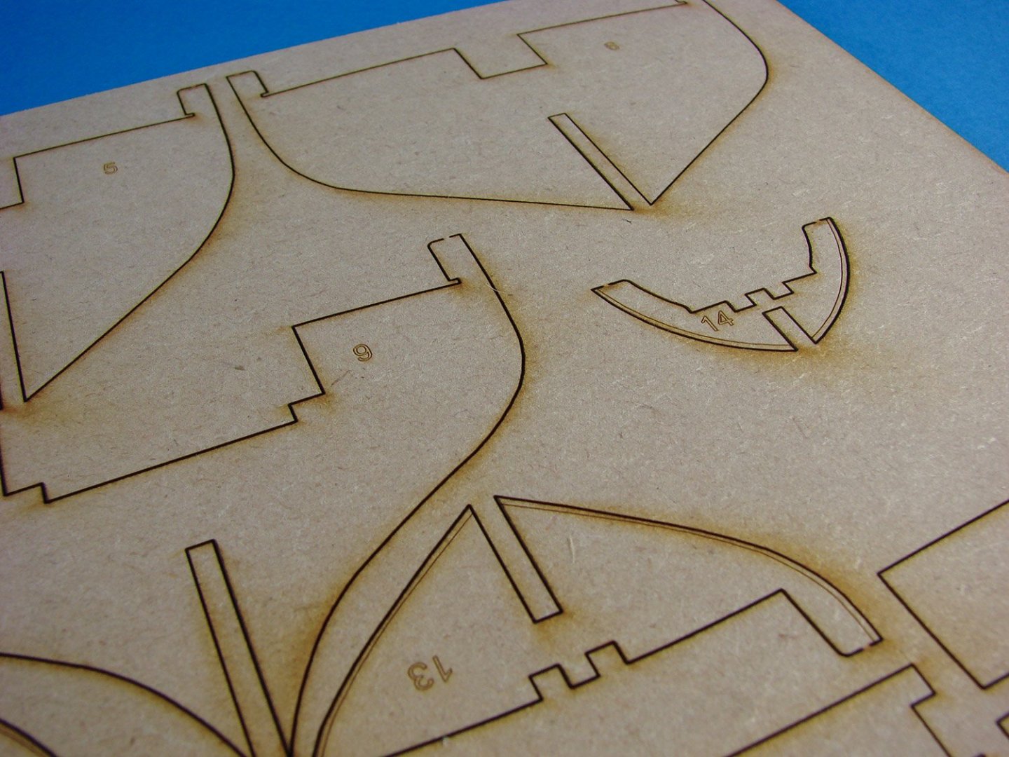
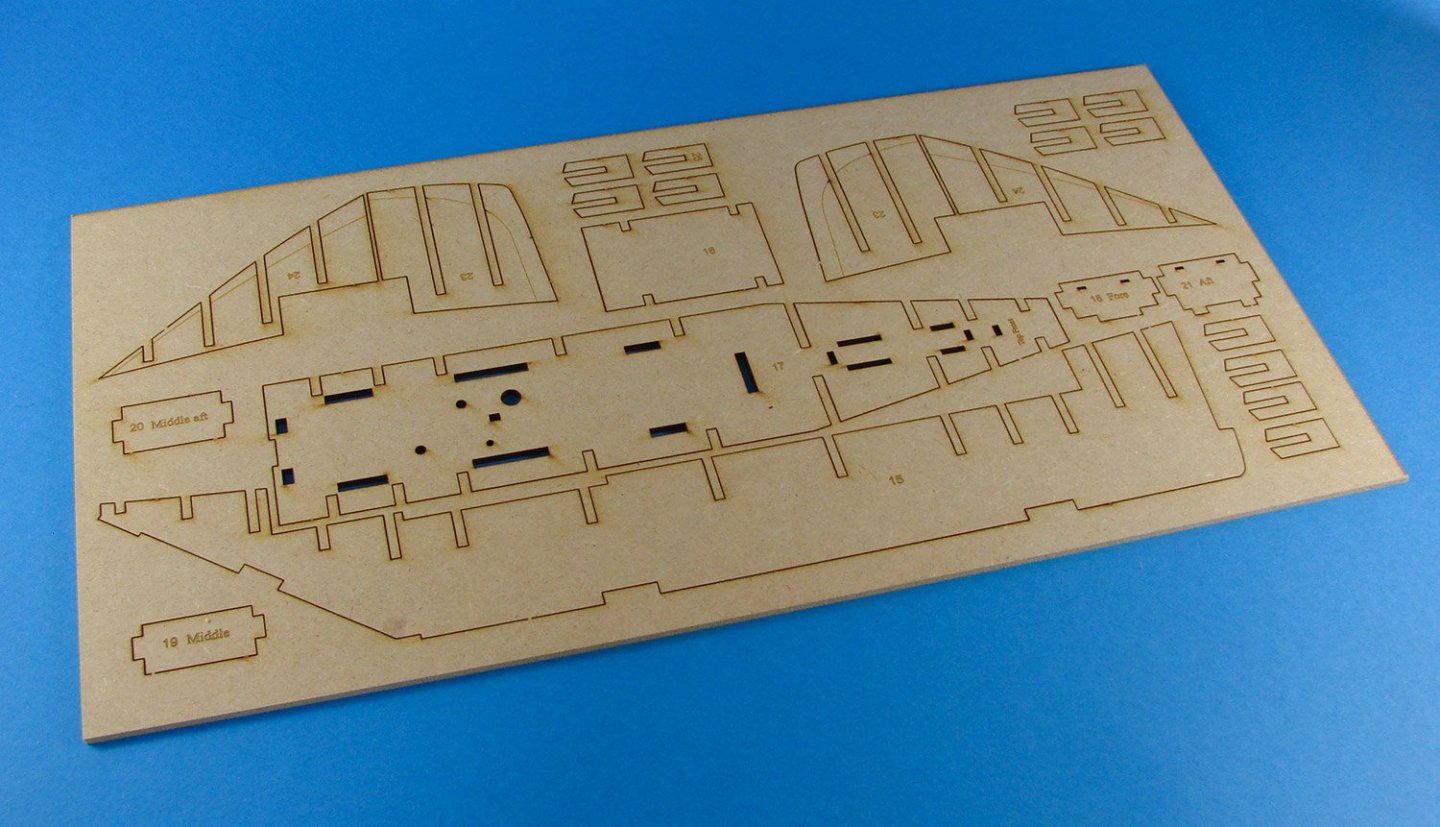
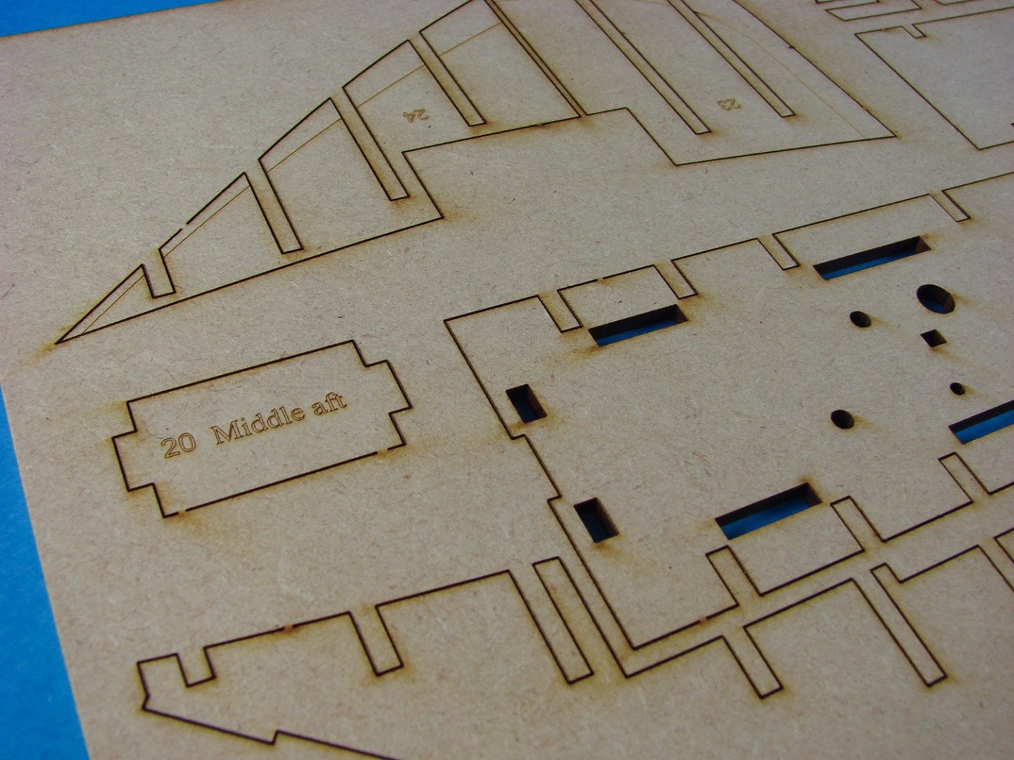
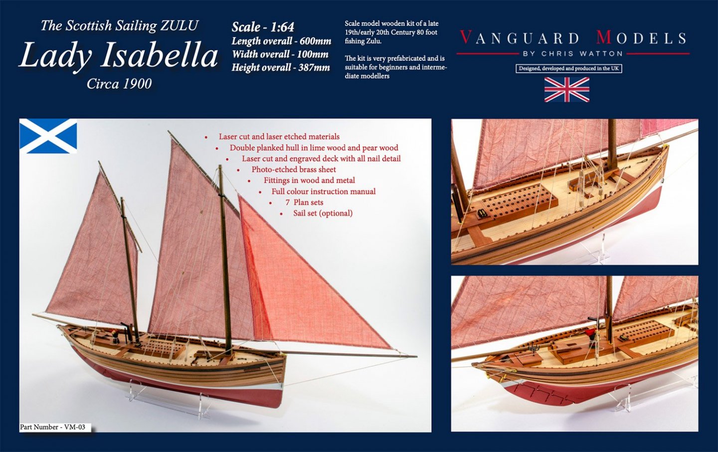
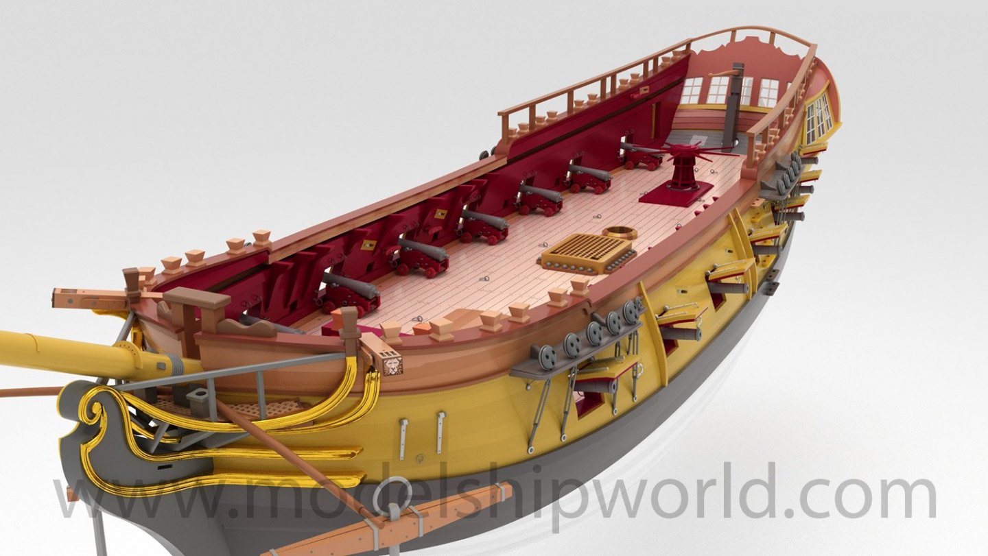
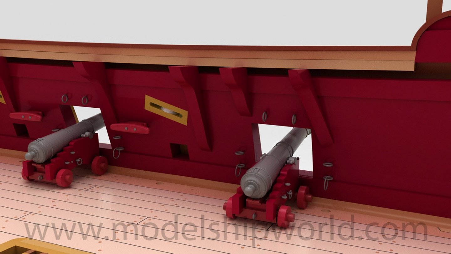
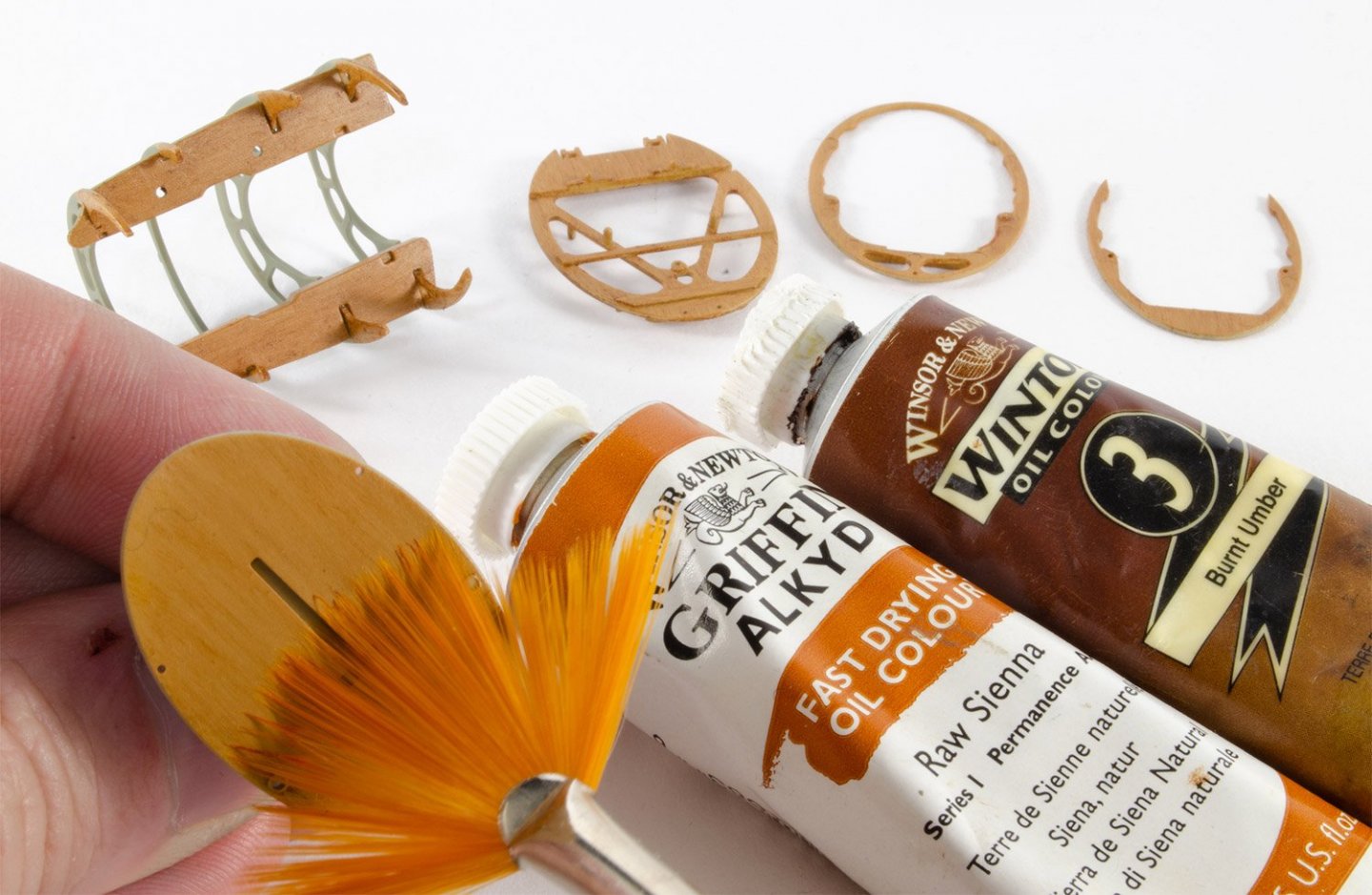
Evening all! Well, I wasn't going to post a log of this until it was either quite advanced or finished. However, I figured that I could well have some serious free time coming my way courtesy of coronavirus, so I may as well spend some time and get this online. This model is a production prototype of Chris Watton's forthcoming 1:64 Zulu-class herring fisher, 'Lady Isabella'. From Wikipedia (https://en.wikipedia.org/wiki/Scottish_east_coast_fishery) Here are some of Chris's photos of these very parts: Here is my recent preview of this model, as the kit I received wasn't a finished product (no box, manual, sails, rig blocks and cord etc) Ok, on with the show... First of all, all MDF parts were removed from the two sheets. All parts are laser-engraved with numbers and some writing, so they are easy to identify. You'll also note some engraved bevelling lines on some bulkheads too. You'll tend to find that the tags that hold the parts to their sheets, are positioned in unobtrusive positions, such as the top of the bulkheads which will eventually be cut away. With all parts removed I did a quick test fit of the main parts. Before any work starts, the superstructure needs to be assembled. To do this, it needs to be put together and glued while sat on top of the false lower deck. This is only to make sure everything is square, and it must not be glued to that part. Note some parts have engraved labels to help orientate them. I mostly use Titebond glue for my work. It was now the turn of the bulkheads to be paid a little attention. Those which have a more acute bevel are engraved as such. Using a Dremel, I removed all the excess material from them on a sedate 9000RPM speed. The Dremel is also used to grind the MDF to the bearding lines on the infilled parts. All bulkheads are now glued into position on the false keel, but this time I use white glue (Evo Stick PVA) as this dries more slowly than Titebond, and allows me some wiggle room until all parts are in place. The kit is made so tolerances are reasonably tight, so you can't really get anything wrong here. The false lower deck has text on it to define the upper side. Chris has selected birch ply for the main deck lower surface. This makes it quite pliable. This is important because you need to be able to flex it slightly at this stage. Each bulkhead has the temporary timberheads notched. The deck slides into these to there's no reason to pin it at the edges. The deck just snaps into position perfectly and site perfectly across the top of the bulkheads. I didn't do a test fit of that deck. I figured that once in place, it wasn't coming out again to easily, so I decided to paint some Titebond around the joints from the underside. I almost forgot to add the reinforcement pieces 7a to either side of bulkhead 7. It didn't matter too much though as fitting them afterwards meant that I could slide them right in underneath the deck and bang into the perfect position. More soon!


- 100 replies
-
- 19
-
-
- zulu
- vanguard models
- (and 2 more)
-
What unusual construction. Very much enjoying this build.
- 175 replies
-
- 4
-
-
- hanse kogge
- shipyard
- (and 1 more)
-
kit review 1/72 Wütender Hund by Shipyard - Hanseatic Cog
James H replied to ccoyle's topic in REVIEWS: Model kits
What a great looking kit. Never seen paints included before either. Looks a very classy release! 😍 -
kit preview 1:64 Zulu fishing Boat - Vanguard Models
James H replied to James H's topic in REVIEWS: Model kits
Technically, it's not pre-cut, but a simple and very effective method of construction that creates it. -
kit preview 1:64 Zulu fishing Boat - Vanguard Models
James H replied to James H's topic in REVIEWS: Model kits
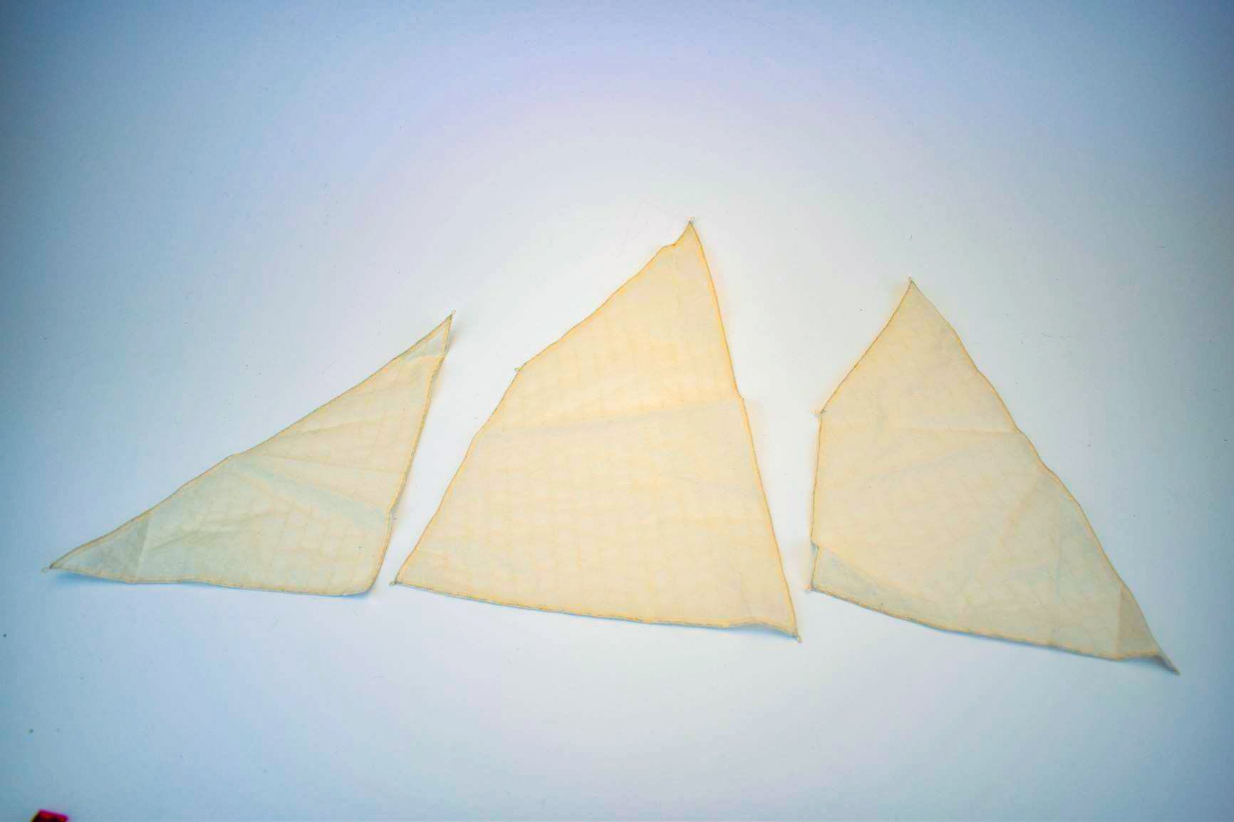
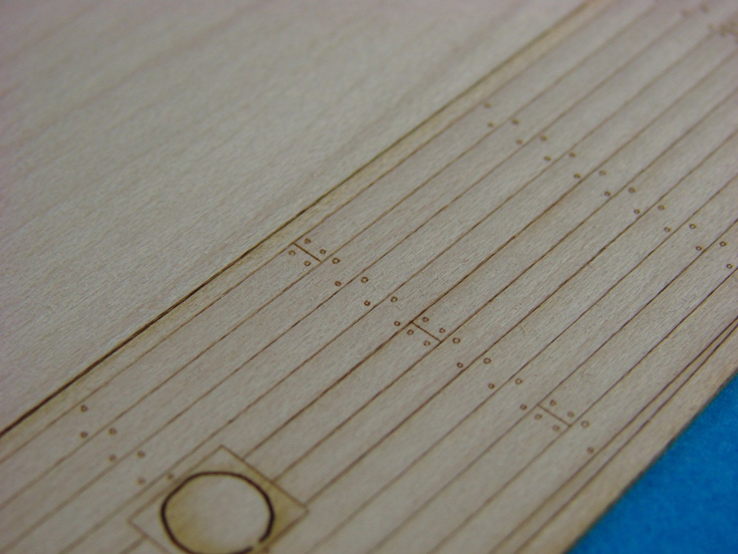
Sails will be an option, but the first sample set just landed. Here you are.... For deck differences, the prototype Fifie has the maple veneer deck, and Chris's Zulu has the 1mm limewood deck, but hard to tell the slightly different colours and closer grain on the maple, compared to limewood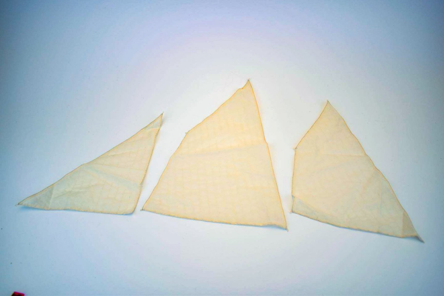
-
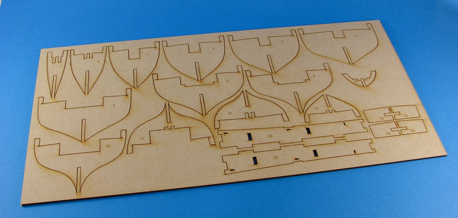
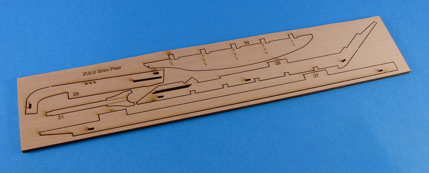
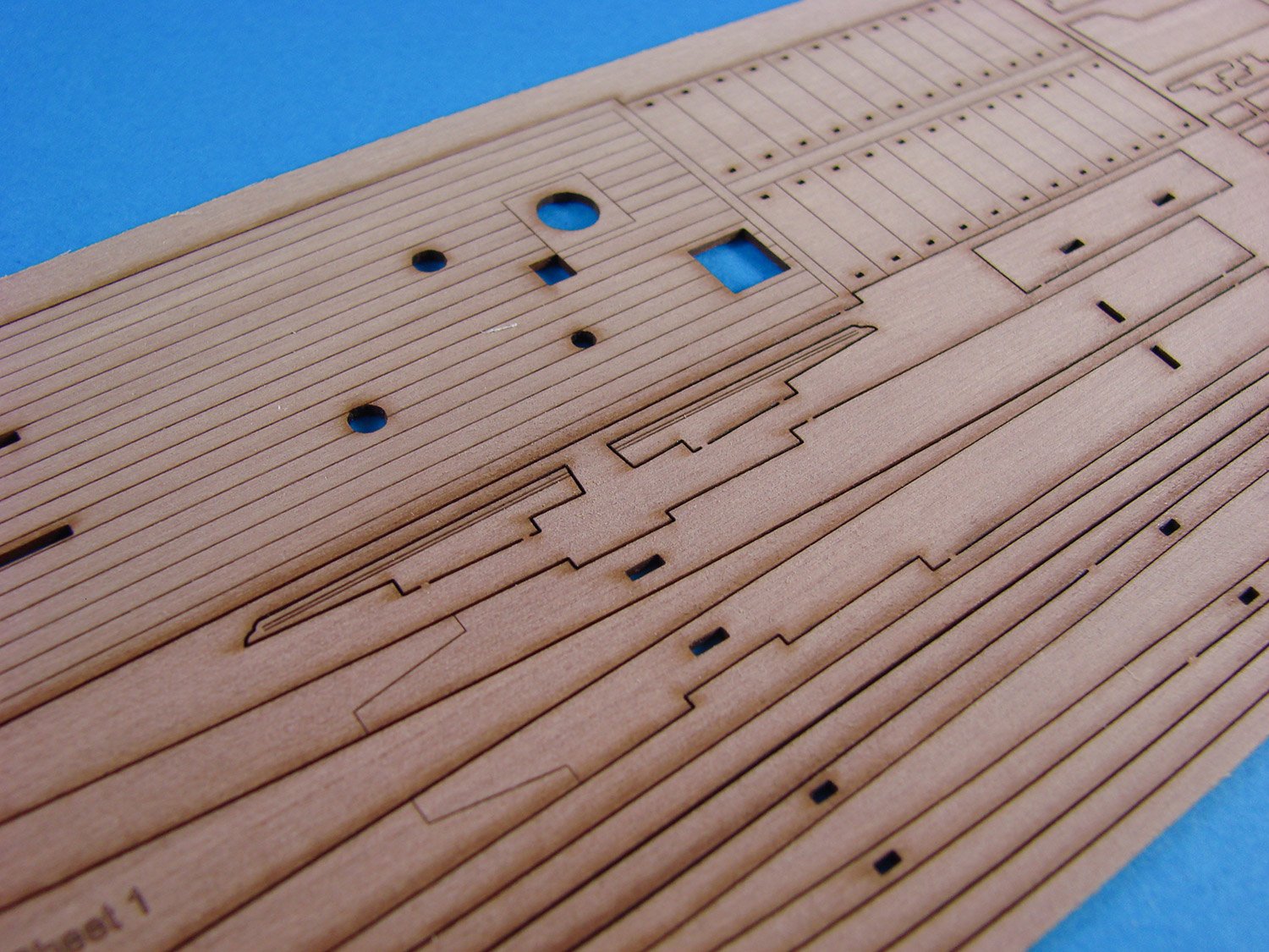
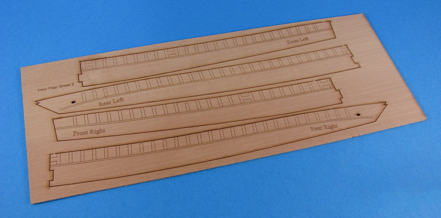
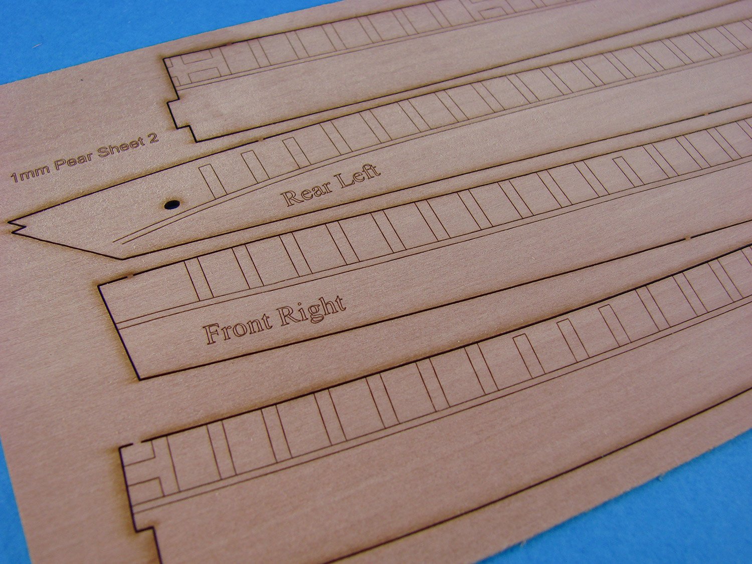
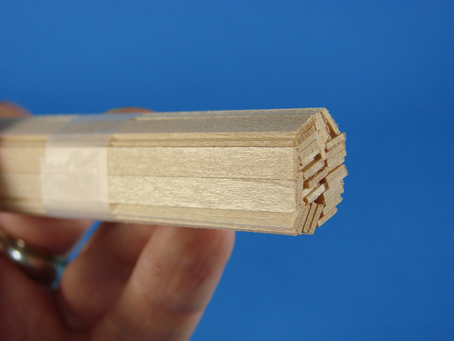
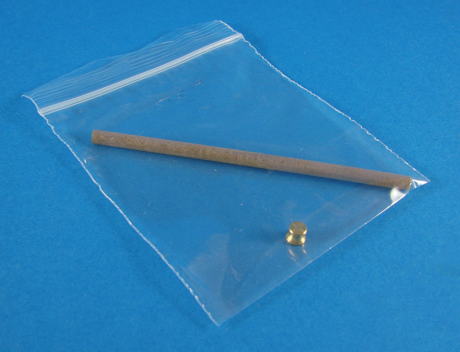
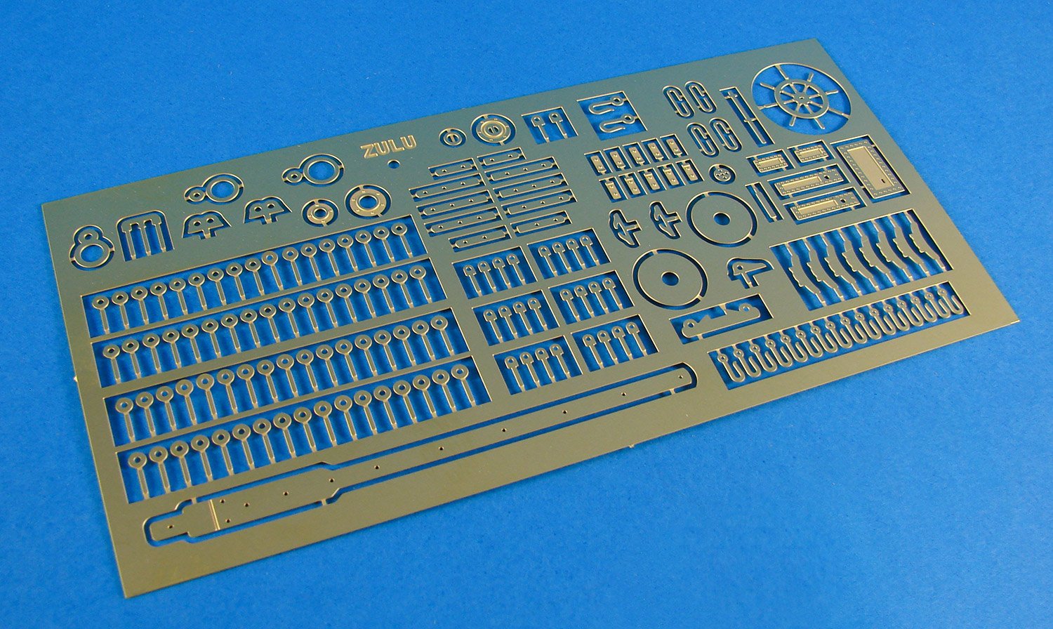
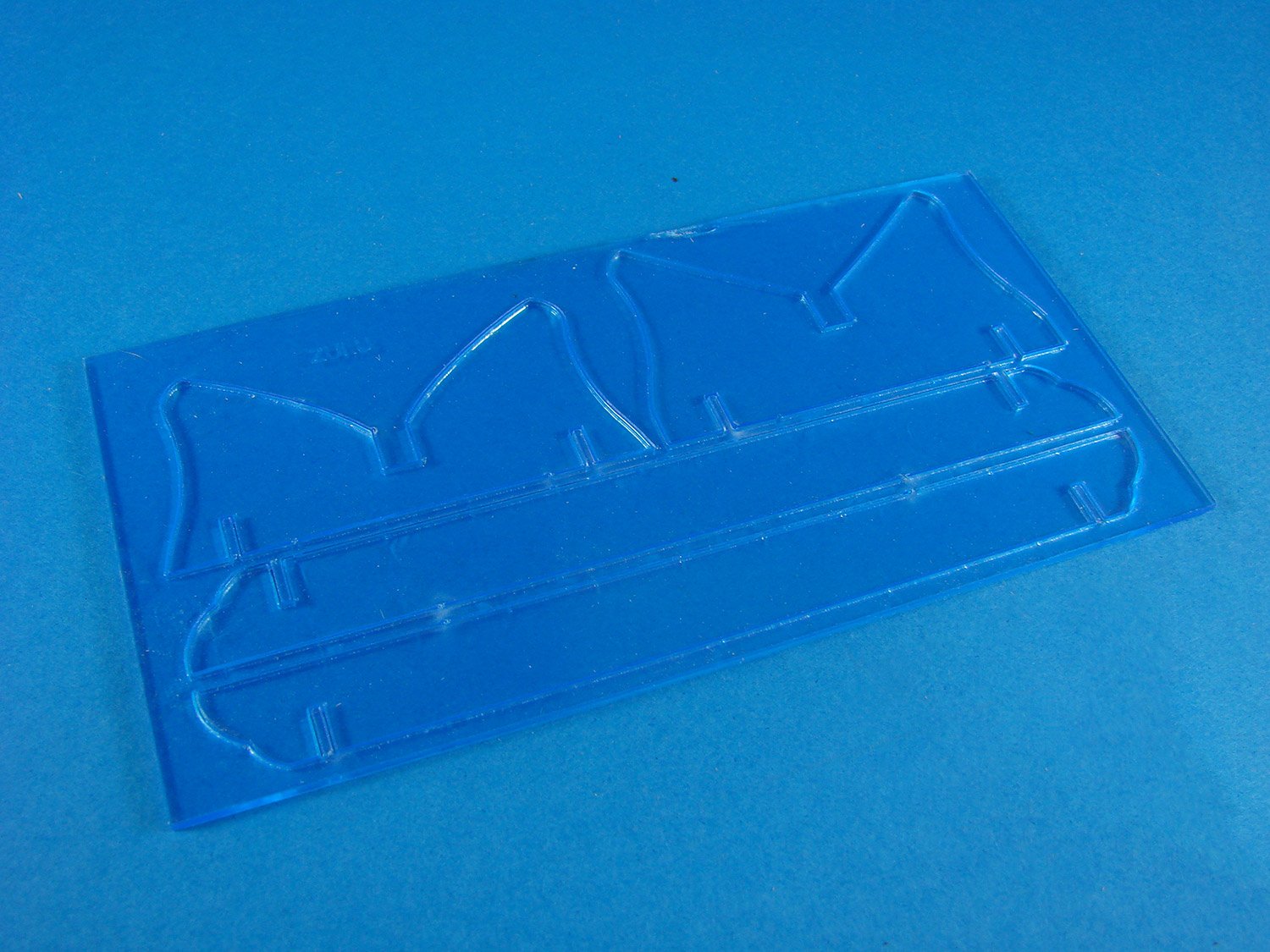
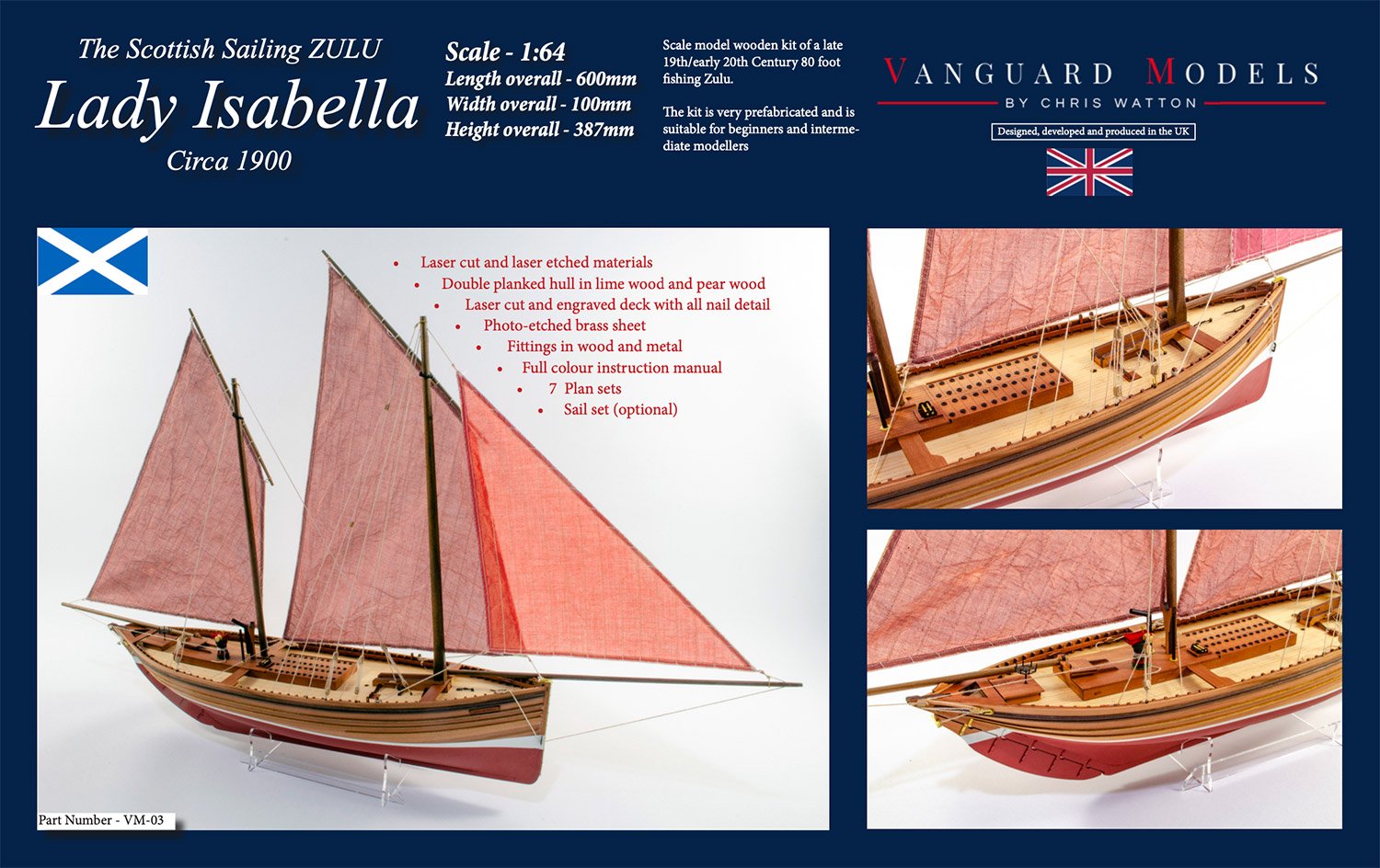
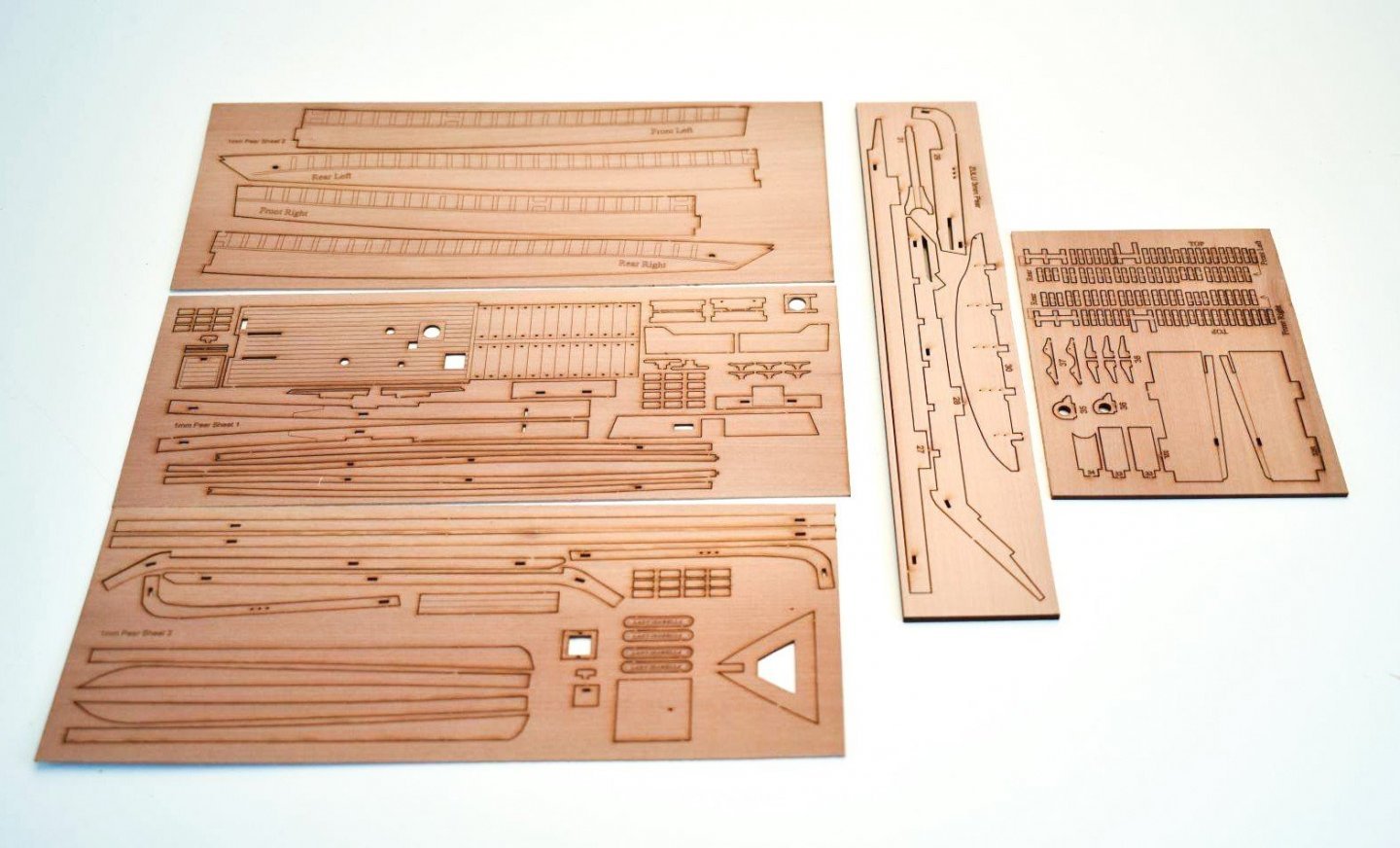
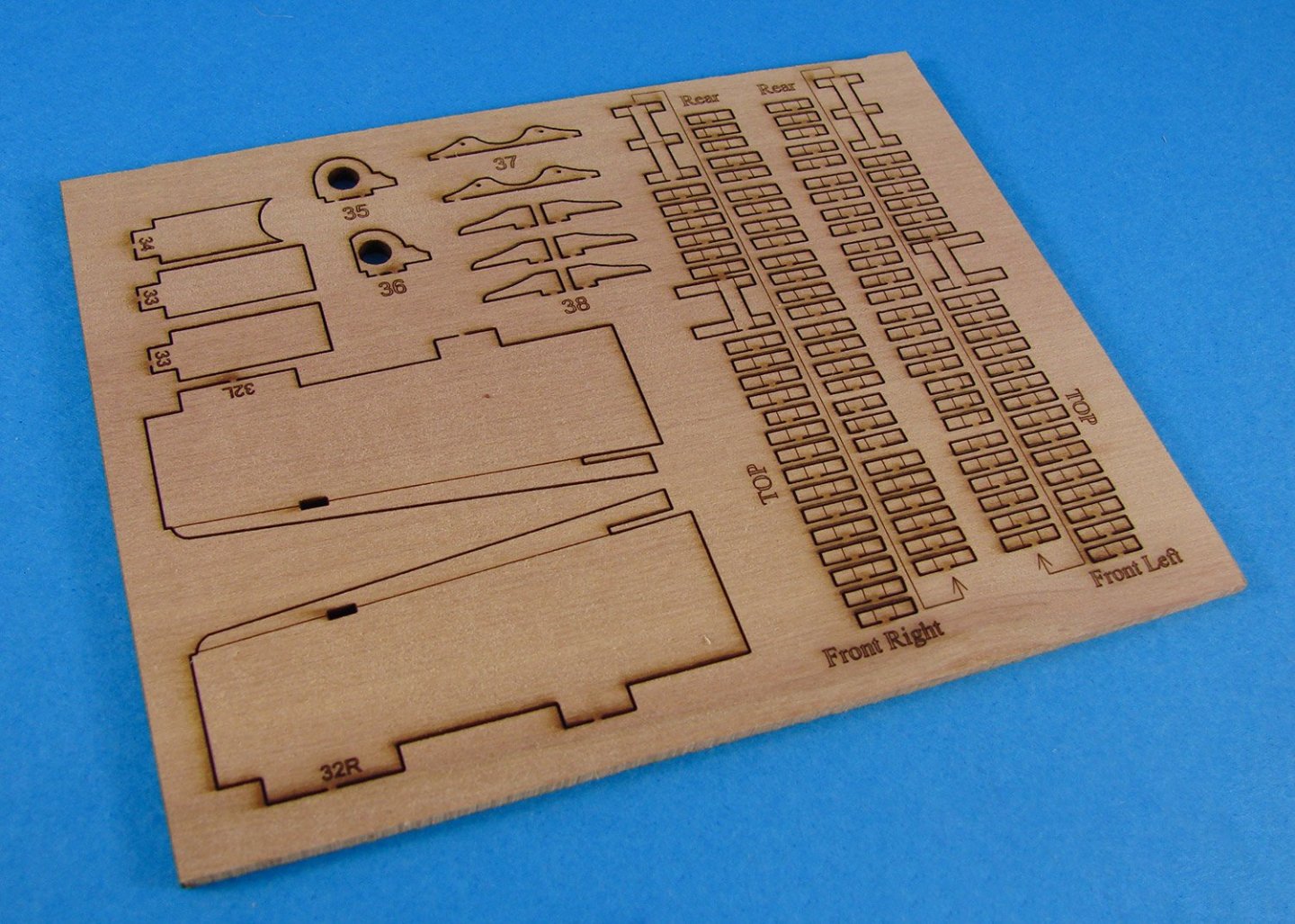
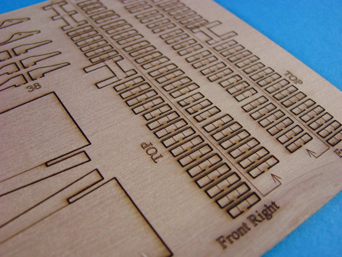
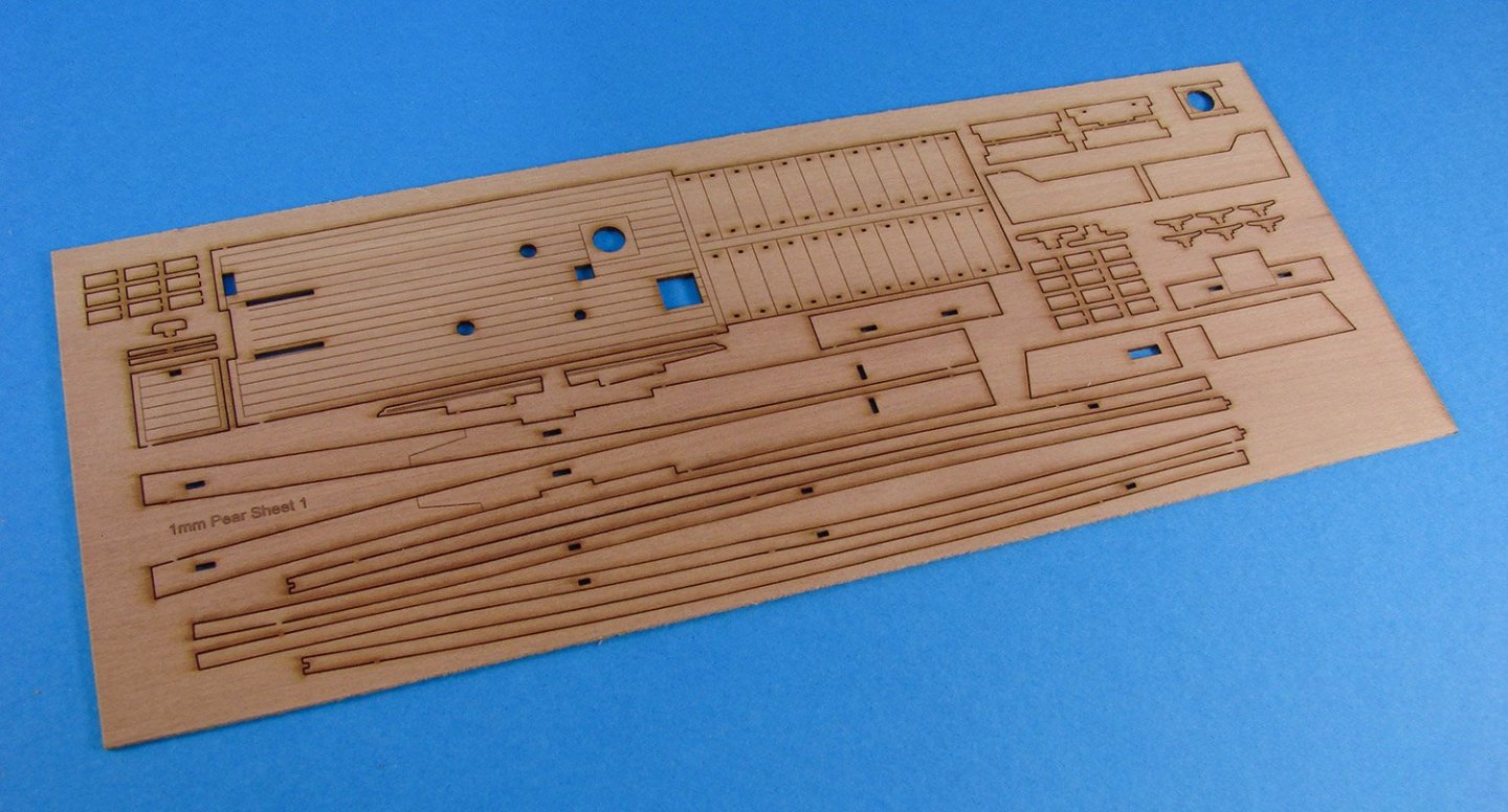
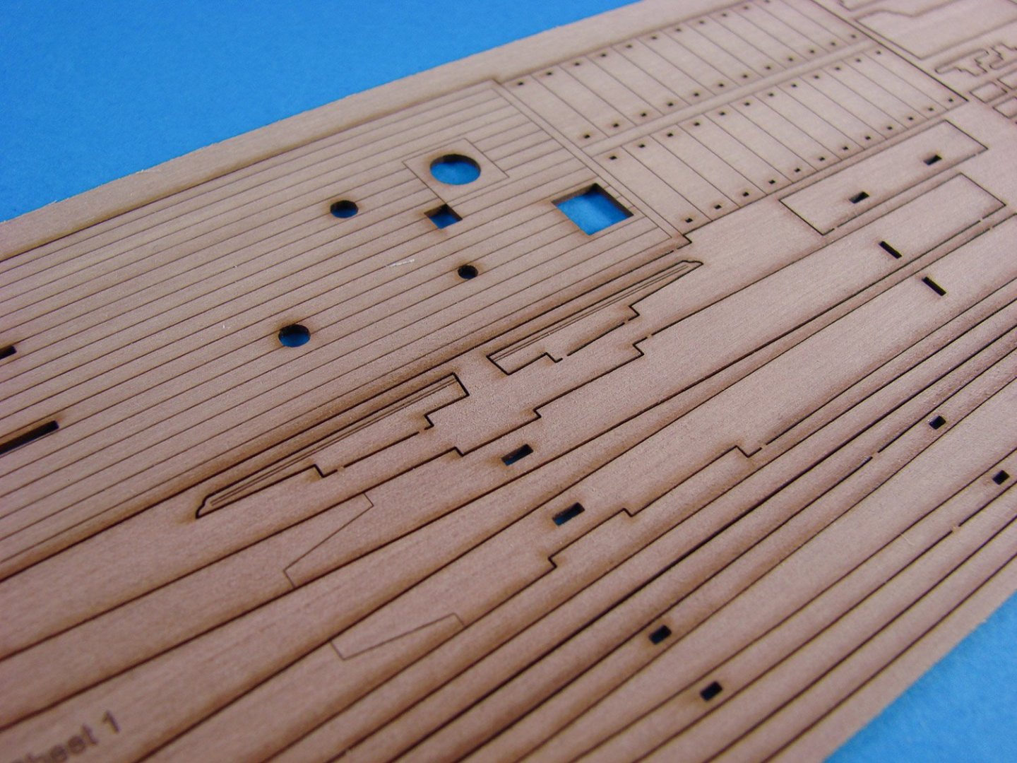
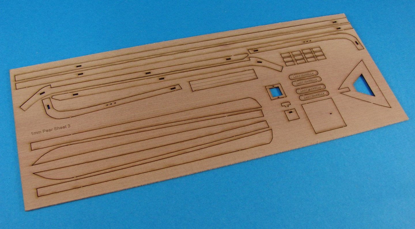
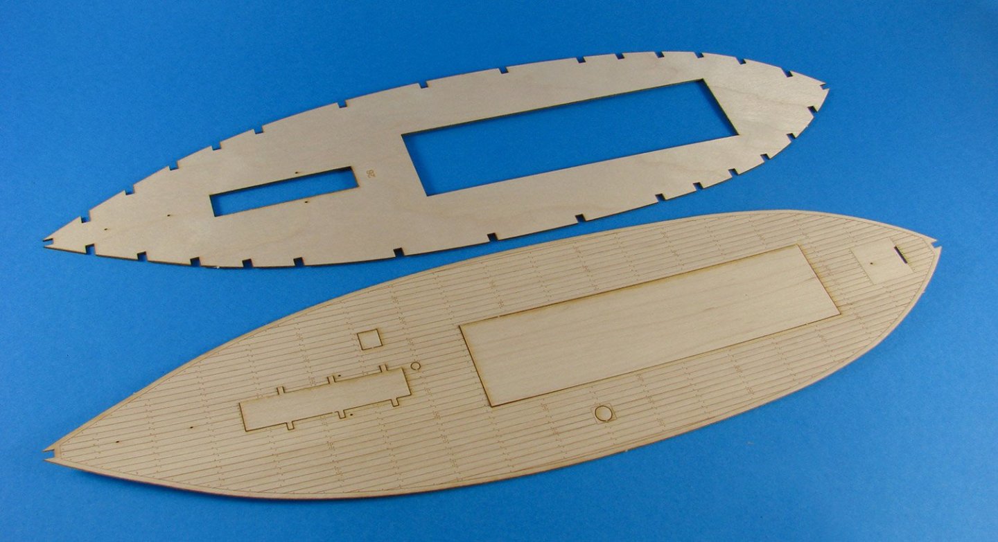
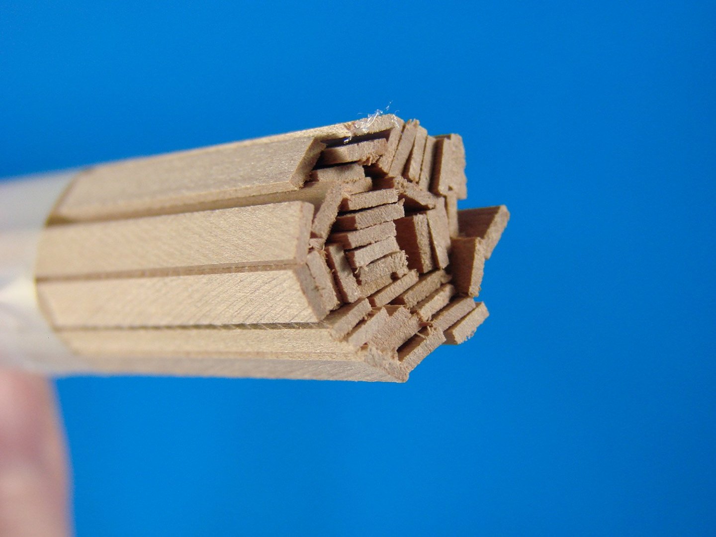
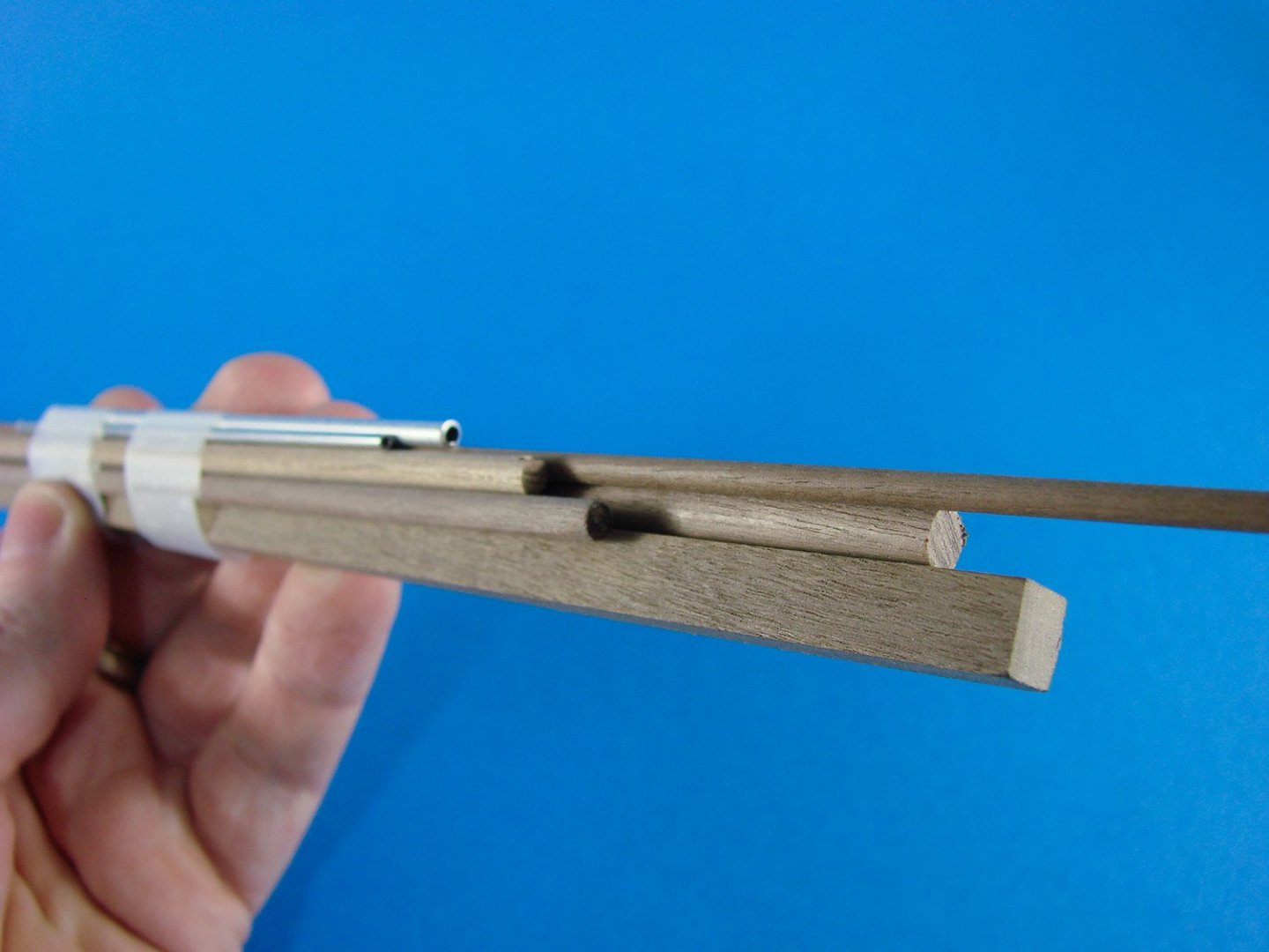
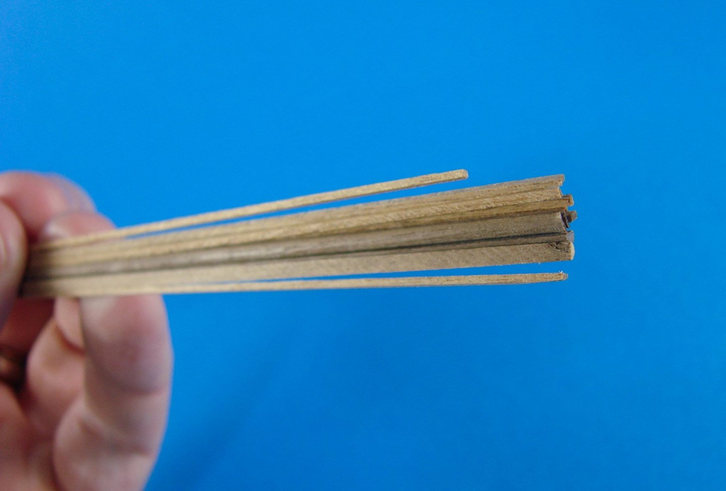
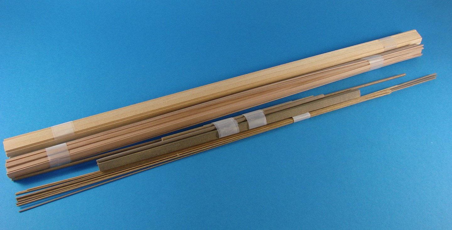
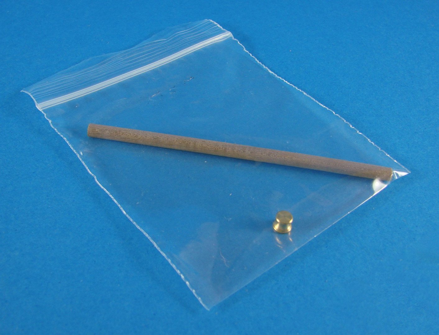
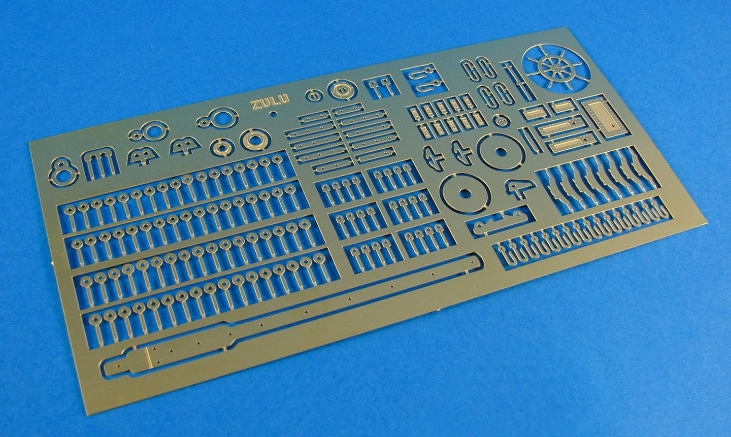
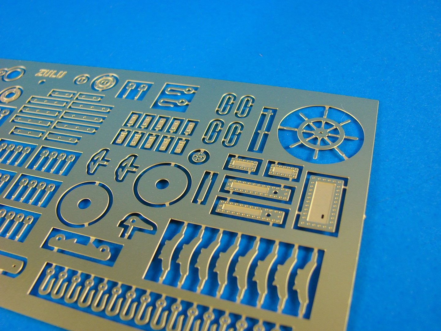
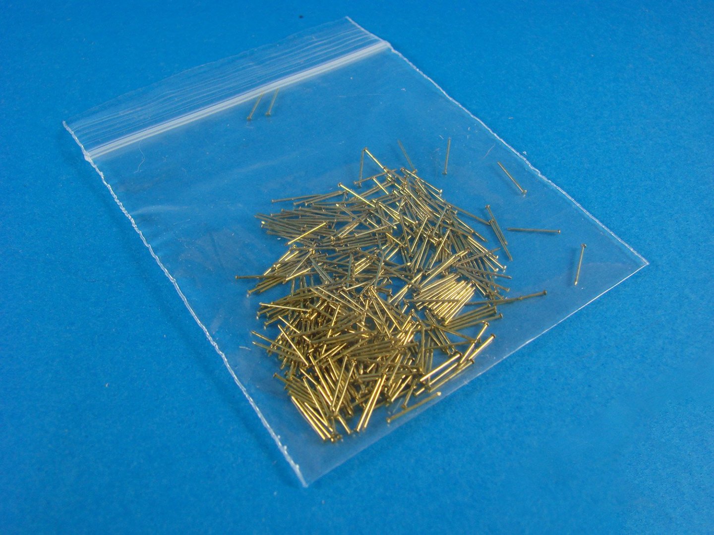
1:64 Zulu Fishing Boat - KIT PREVIEW Vanguard Models **Coming soon** Vanguard Models are currently around 2 months (give or take) from releasing two new kits which are suitable for both beginner and expert alike, but of course engineered to help those who want to try their hand at modelling a ship/boat in timber. Both models are in 1:64 and both are working vessels; fishing boats. These are the Zulu and Fifie class of vessel which tended to operate around the south-eastern coast of Scotland, mainly as herring fishers. If you know Chris's style of design, then you'll see it here in this preview kit I have for the Zulu. This is a preview only and isn't designed to be a review. It's simply to show you the basic box contents before Chris finishes the kit. Firstly, it isn't a finished-boxed product, being sent to me in a regular shipper box. It also has no instructions and no plans at this stage, and rigging blocks/cord/sails will be with me later. My own build which Chris wants to use for a box-art photo, will be made using his prototype photos that I'm currently editing for his instruction manual. Sails will be provided as an extra, should the modeller want them. Many don't use sails, so you'll not pay for something you won't use when you buy the initial kit. Despite the model also being pitched at newcomers and novices, no poor quality materials have been used. You get pear in this kit, with an option to buy with a maple deck instead of lime. The Zulu contains: 2 x 3mm MDF sheets 3 x 1mm pear sheets 1 x 2mm pear sheet 1 x 3mm pear sheet 1 x 2mm acetate sheet 1 x 0.8mm ply (single part) 1 x 0.7mm maple or lime wood laser cut/engraved deck (lime is standard) 1 x 0.4mm PE sheet Timber strip Metal tubing Not seen in this photo are the rigging blocks and cord, and the optional sails. MDF Sheets One thing you'll note here is that Vanguard Models are now using laser engraving on their parts, so everything is pre-numbered and there are also bevelling lines so you can roughly shape bulkheads before assembly to the false keel. Final shaping can be done later. 1mm pear sheets These are very nice indeed. Timber quality is excellent, and I love the pink hues of this stuff. Note that the bulwarks (supplied in halves) have the positions engraved on them for the timberheads. The first two lower planks are also included to take the guesswork out of those shapes near the keel. A rabbet has also been cleverly engineered into the design, and you won't need to cut or chisel a single thing to create it! The rabbet will help those second planks sit snugly into position. 2mm pear sheet 3mm pear sheet 2mm acetate sheet All models from this company have clear acetate stands supplied with them, and this includes these two fishing boats. These just push together with no need for adhesive, although you could, if you wanted to, drop a little PVA into the slot as it will dry clear. The acetate is covered in a blue plastic film which you first peel off, as seen here. A benefit of a clear stand is that it won't hinder the view of the completed hull! 0.8mm ply (single part) and 0.7mm maple deck All kits, as standard, will be supplied with an engraved lime wood deck. The kit which I've been sent has the maple option. As you can see, it does look really neat, and the engraving is excellent, including proper trunnels instead of just dots. This deck will sit atop the ply one seen here, but only when the hull is built (and painted). Strip wood and tube Three bundles of materials are supplied with this kit, all of high quality. The alloy tubes are for the flues. Materials are 1x5mm limewood for first planking, 1x4mm pear for second planking, and walnut for the rest (dowels, half round strip and 1x1mm strip) Photo Etch & errata A reasonable size PE sheet is included, manufactured from 0.4mm brass. Brass nails are the excellent Amati ones with no malformed heads or points etc. Probably the best I've ever used. As I say, this isn't a complete kit. It needs the rig, blocks, optional sails, instructions, plans and a box, but it should give you a good idea about how the finished product will look. Here's a photo of the prototype, so far.


- 11 replies
-
- 16
-
-
Great to have you with us and posting again. Congrats on beating that awful disease! ✌️
-
Old habits die hard with me as I carved away those nubs with a scalpel. I sometimes think I'm still working on plastic models 🤪
-
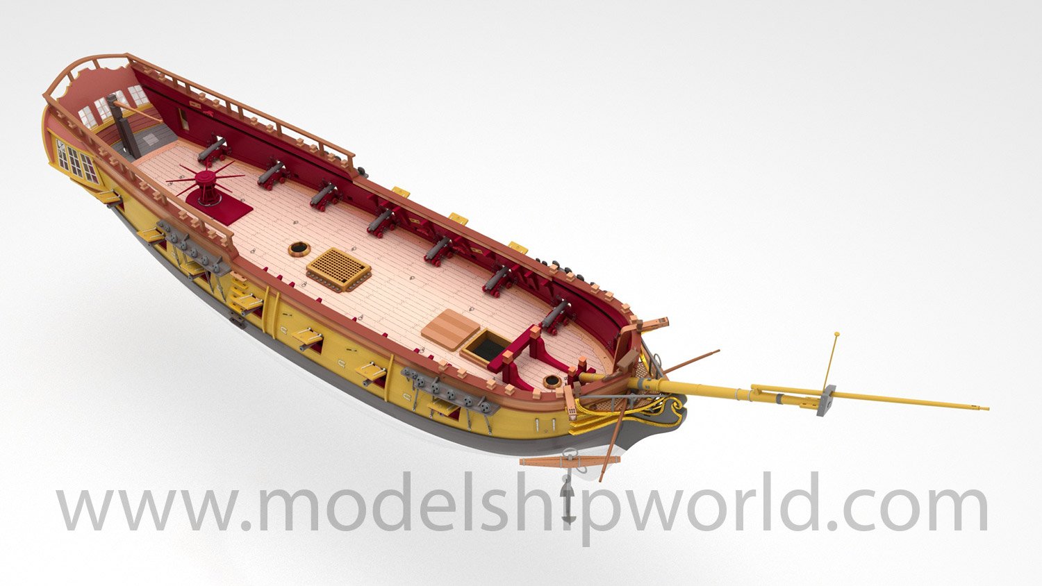
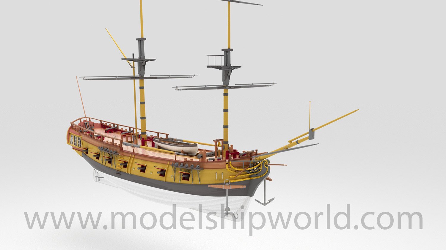
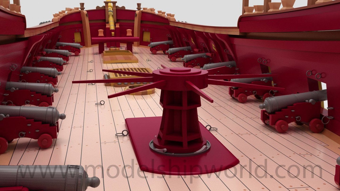
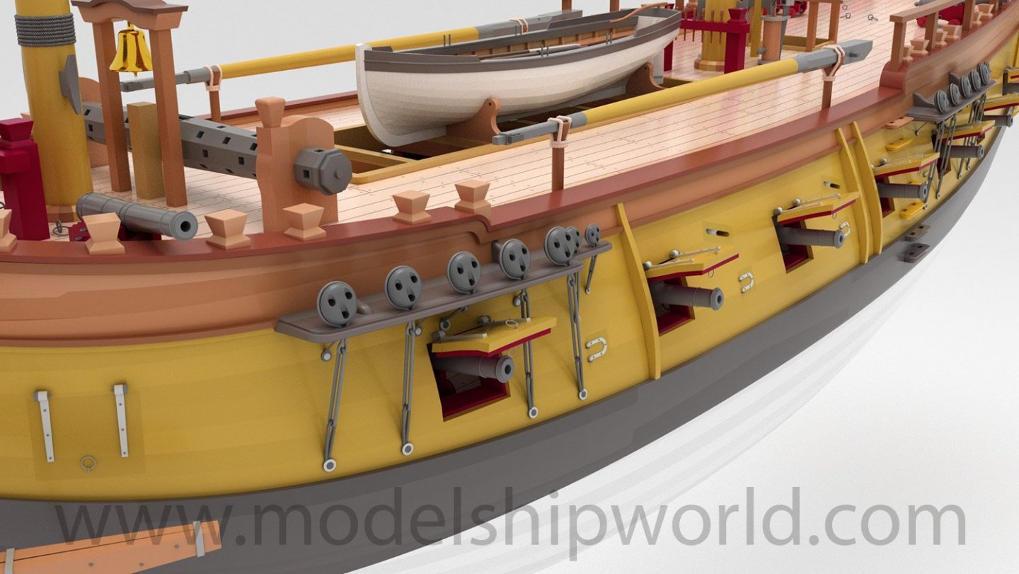
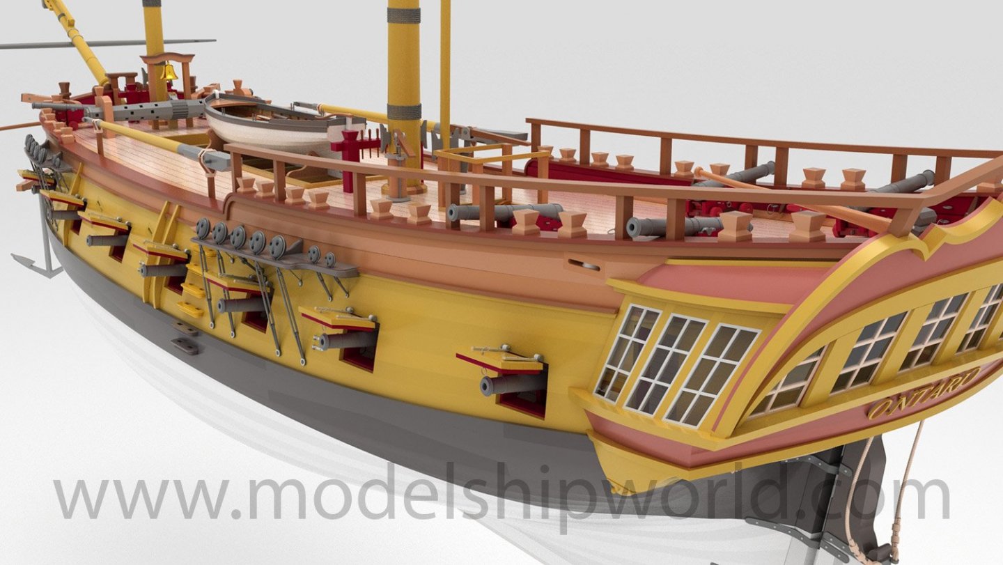
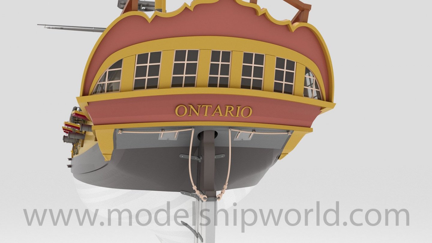
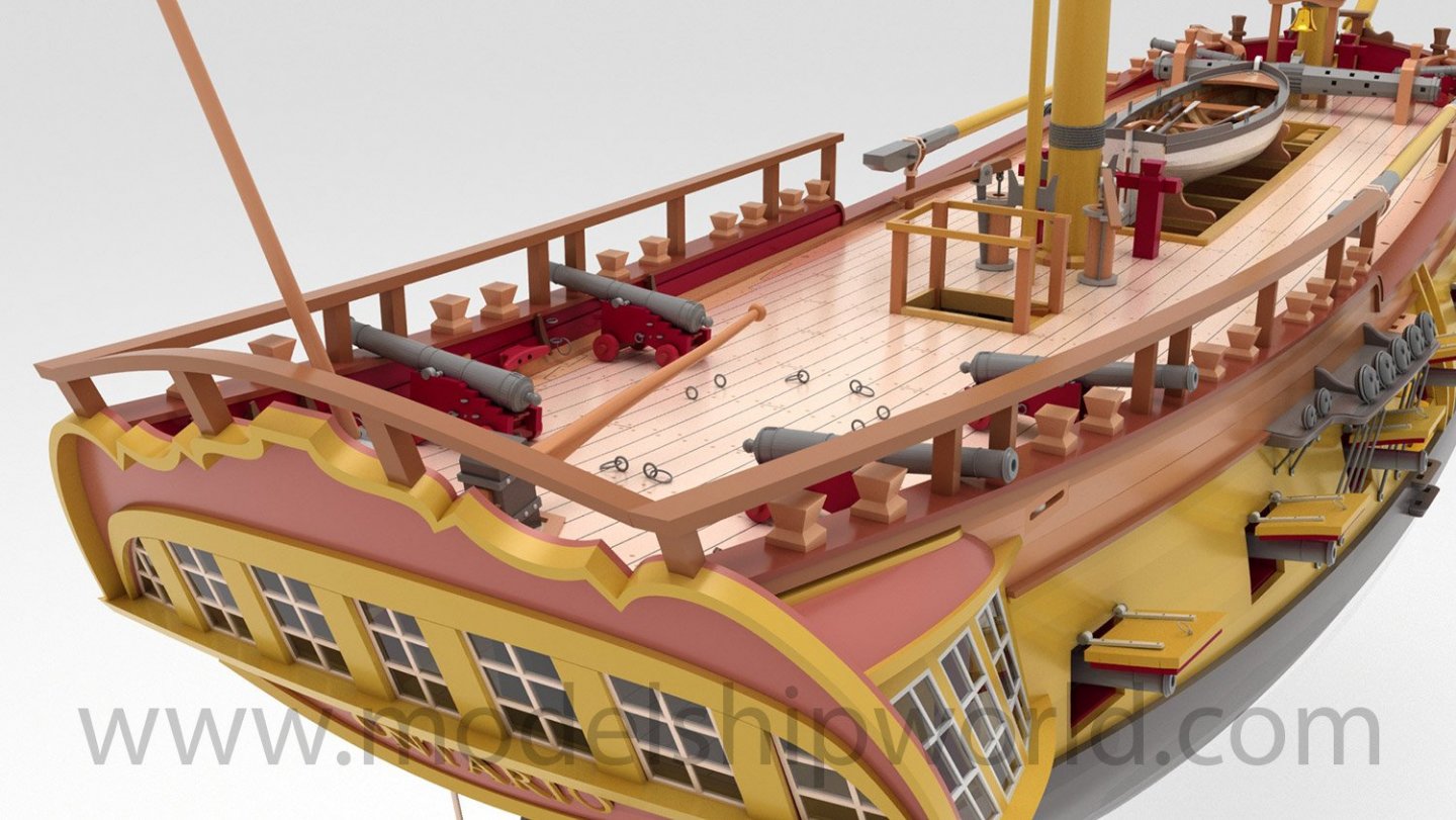
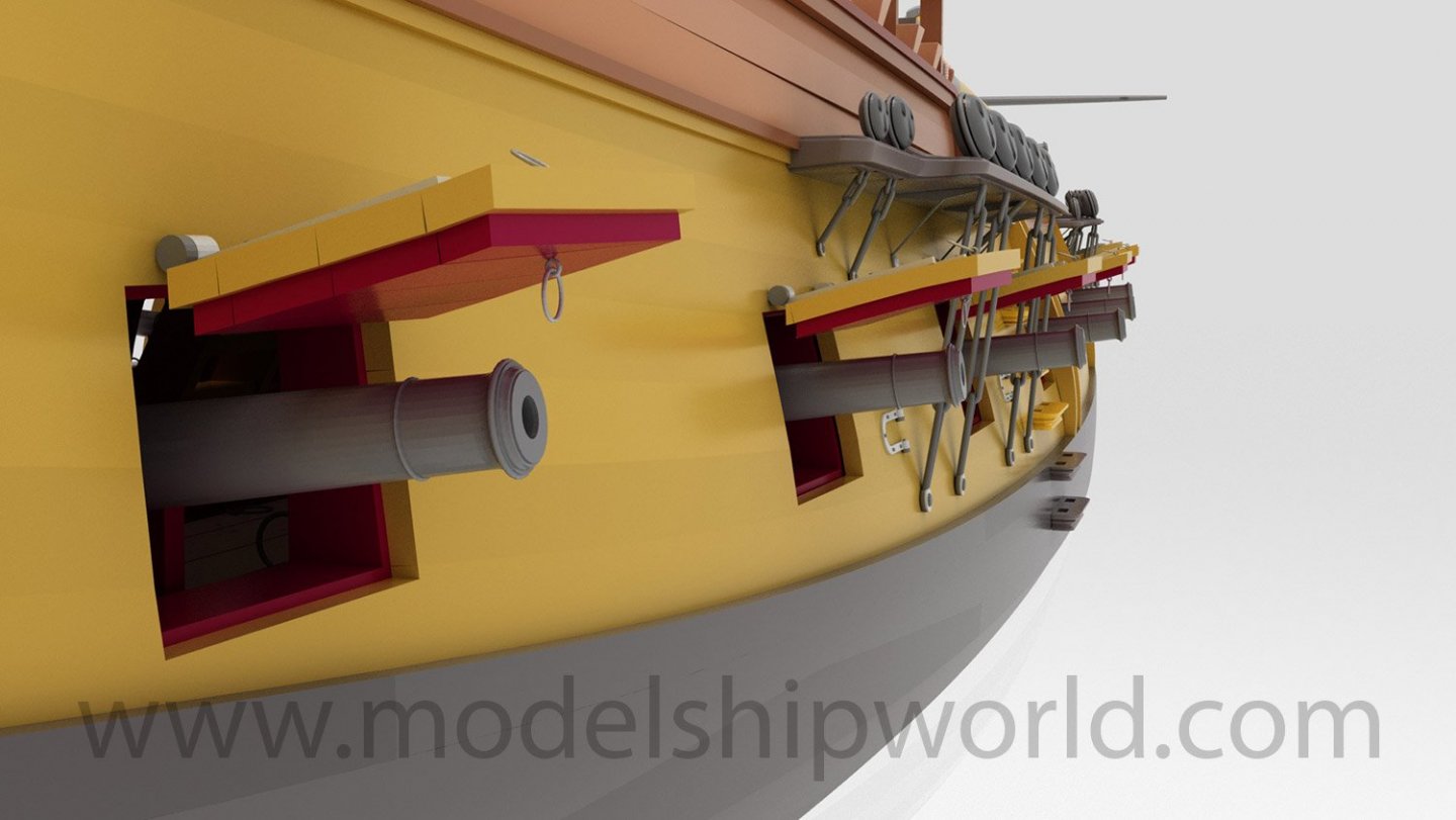
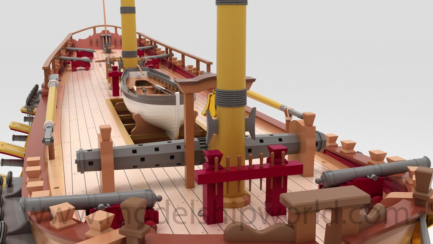
They are renderings. The kit is mainly wooden.
-
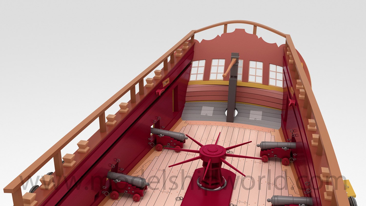
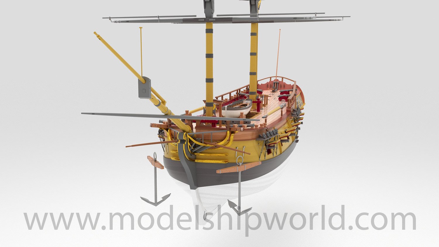
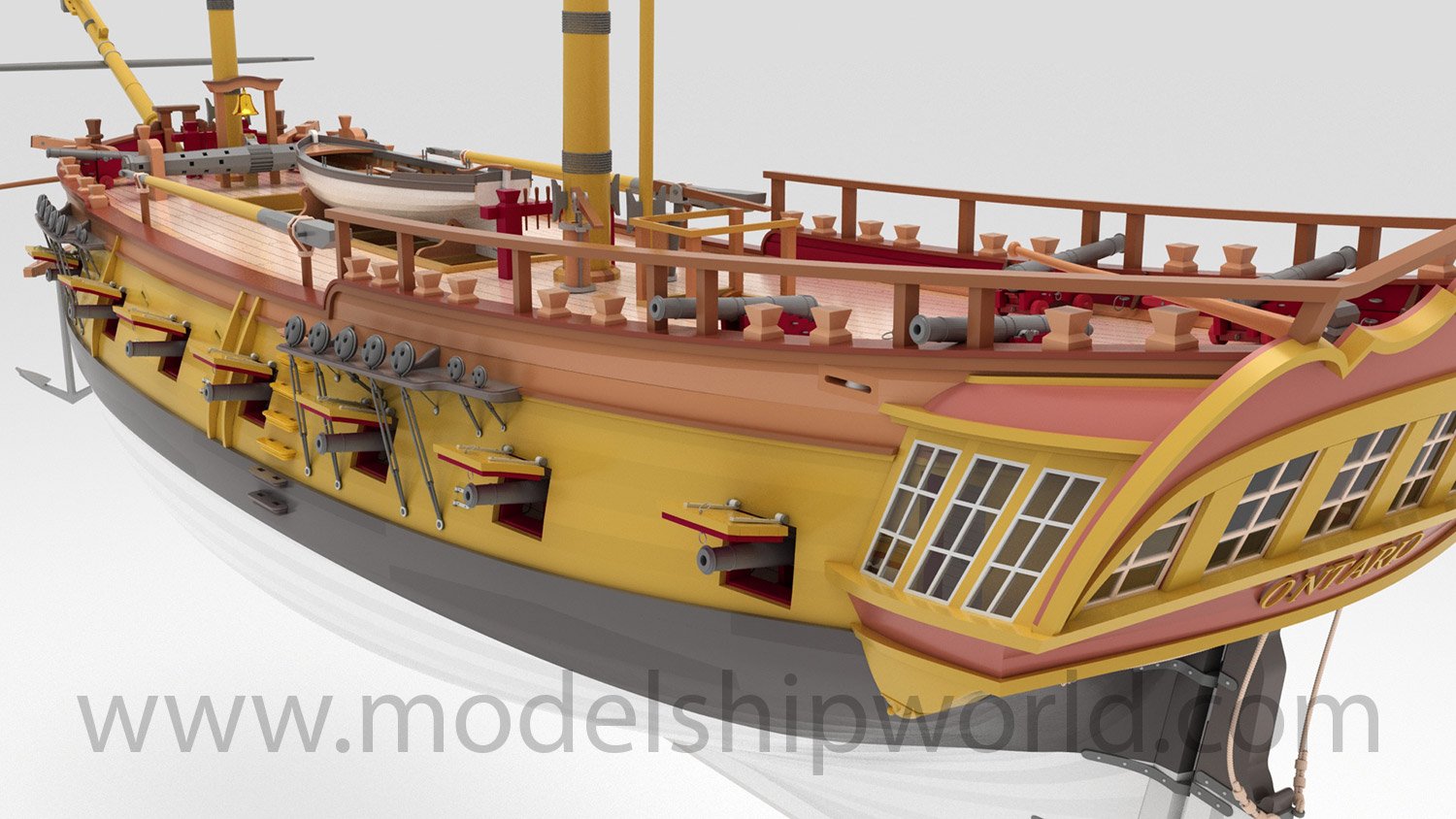
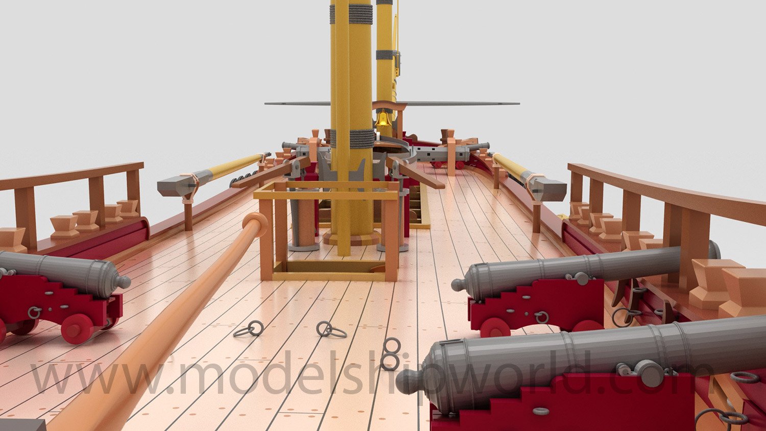
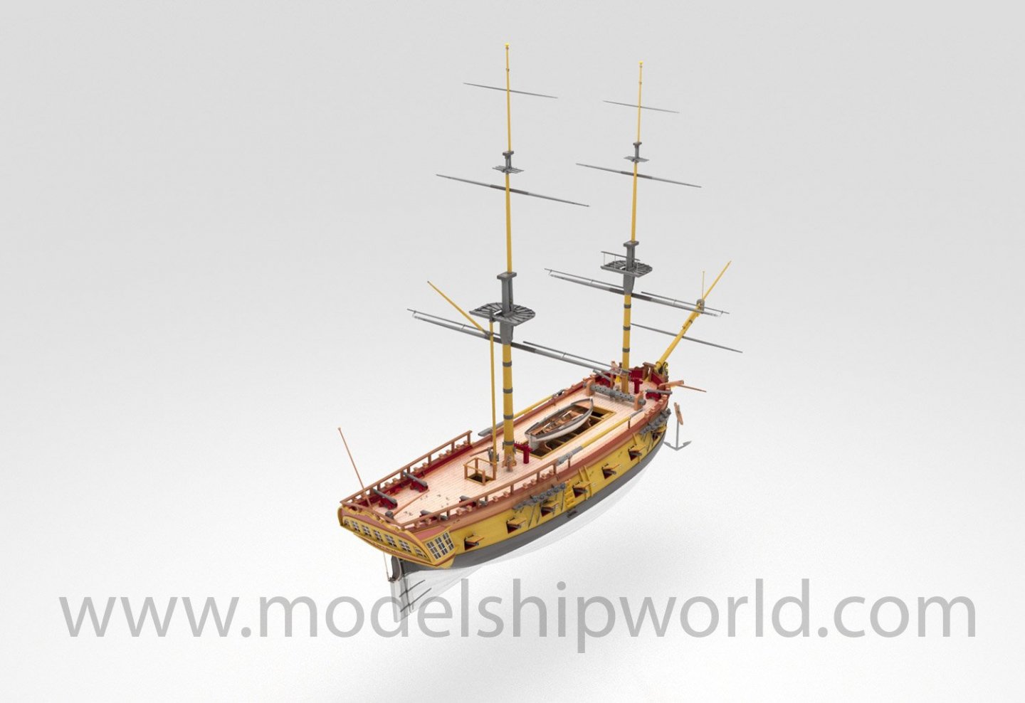
Hi all, MarisStella, in cooperation with The Art of Age of Sail, have just released their new kit, the 1:48 HMS Ontario. This is a multimedia kit, including many traditional elements, but also some 3D-printed , resin, and photo-etched parts. Finished model will be 81cm long. We promise to being you an in-box review of this as soon as we can. http://www.marisstella.hr/gotovi_modeli_galery.php?id=1111&tip=2&hms-ontario-81cm-1-48


-
You will NOT be disappointed! 😆
-
I'll have a Zulu with me on Wednesday.....something to fill a few weeks until Victory lands. Chris wants me to build for the kit box art. Build log incoming....
-
No, I was there a couple of weeks ago on a surprise treat for my 50th. My wife knew I'd like to be next to the sea in a pub selling great whisky and stuffed with sailing ephemera. 🤪
-
kit review USS Missouri (or any Iowa class) 1/350 by Joy Yard
James H replied to Tigerdvr's topic in REVIEWS: Model kits
What a great looking kit, and the presentation is excellent too. Thanks for sharing. -
I can promise that you'll love this kit. When it does become available, I hope you'll share your build here. Chris Watton is a member here too, and as we'll have both built this, there will be plenty of help if you need it. Oh, by the way....
-
You are right....all that needs to be done is for me to get the new production prototype built. There were small changes to this over the one Chris built as he opted to improve things further as he built it, but was too late to include in his original manual, these changes are now done. The model, as it stands, is now finished in design, so with me completing the manuals, there's no reason why Amati can't get the parts put into production. My model needs to stay consistent in appearance to Chris's original design prototype, so it will be painted in the same colours and not the new ones. Chris's model will be on the box art, so it would look strange for the one in the manual to be a different colour. Remember, the new colour is evidence from their latest findings, but still, as far as I'm aware, not definitive. No one really knows the exact shade, so I'll stick to convention. However, I will add some notes in there about the alternative new colour she's painted in, to give the modeller an option, and hopefully provide a reference on what paint to use.
-
Haha! I'm not building it in a pub! 🤣
-
That's The Olde Ship, at Seahouses, Northumberland, UK.
-
Ok, some news. The laser and photo-etch parts are now being produced. As around 7yrs had elapsed since Chris completed this, the laser cutting company had made changes to its equipment, meaning the sheets had to be a different size. Some work was done to move all the parts around to fit the new sizes. There were a few questions about certain aspects of the design, but we are now there. Amati hope to have the parts (both laser and PE) with them in around 10 days, so if that goes to plan, I should have everything in 2-3 weeks, and I can start a build log here as I create the work needed for the instruction manuals. There will be at least two shiny, perfect-bound books for this....possibly three. Having spent 7 months pouring over Chris's original manual, I think there will be around 1500+ images needed, perhaps more. That will be interlaced with some extracts from the drawings too. I know many folk are wanting this kit, so I promise to work as quickly as I can to complete everything up to where masting is needed. Masting and rig will be done via the plan sheets, as is traditional.
-
Absolutely correct. I've lived under deadlines for 7-8yrs, every single month. Sometimes I've had 2 weeks to build two models for two titles at the same time. It's been arduous.
-
it will be fully published in a magazine, but here's some photos... 🤫


- 19 replies
-
- 15
-
-
I reckon for every mag project I've built, there's probably another I've had to shelve...mostly temporarily, sometimes completely. I trip over those hiatus'!
-
Some stuff goes on hiatus from time to time. It's an occupational hazard of being a member of a magazine's contributor team. The whole scene, with its hard deadlines, has burned me out in plastic modelling, so I'll shortly be quitting and moving back to ships. After Victory, I'll have time to finish up that gorgeous Orient Express carriage too.