

Mark Pearse
-
Posts
701 -
Joined
-
Last visited
Content Type
Profiles
Forums
Gallery
Events
Posts posted by Mark Pearse
-
-
Hi Tony,
Yes I know the sky-blue Byzance. This half model is to be an addition to our trophy wall, the first Karoo trophy race was held this year Sunday 21st February, won by the gorgeous Peter Cole signed Tanami.
-
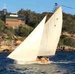
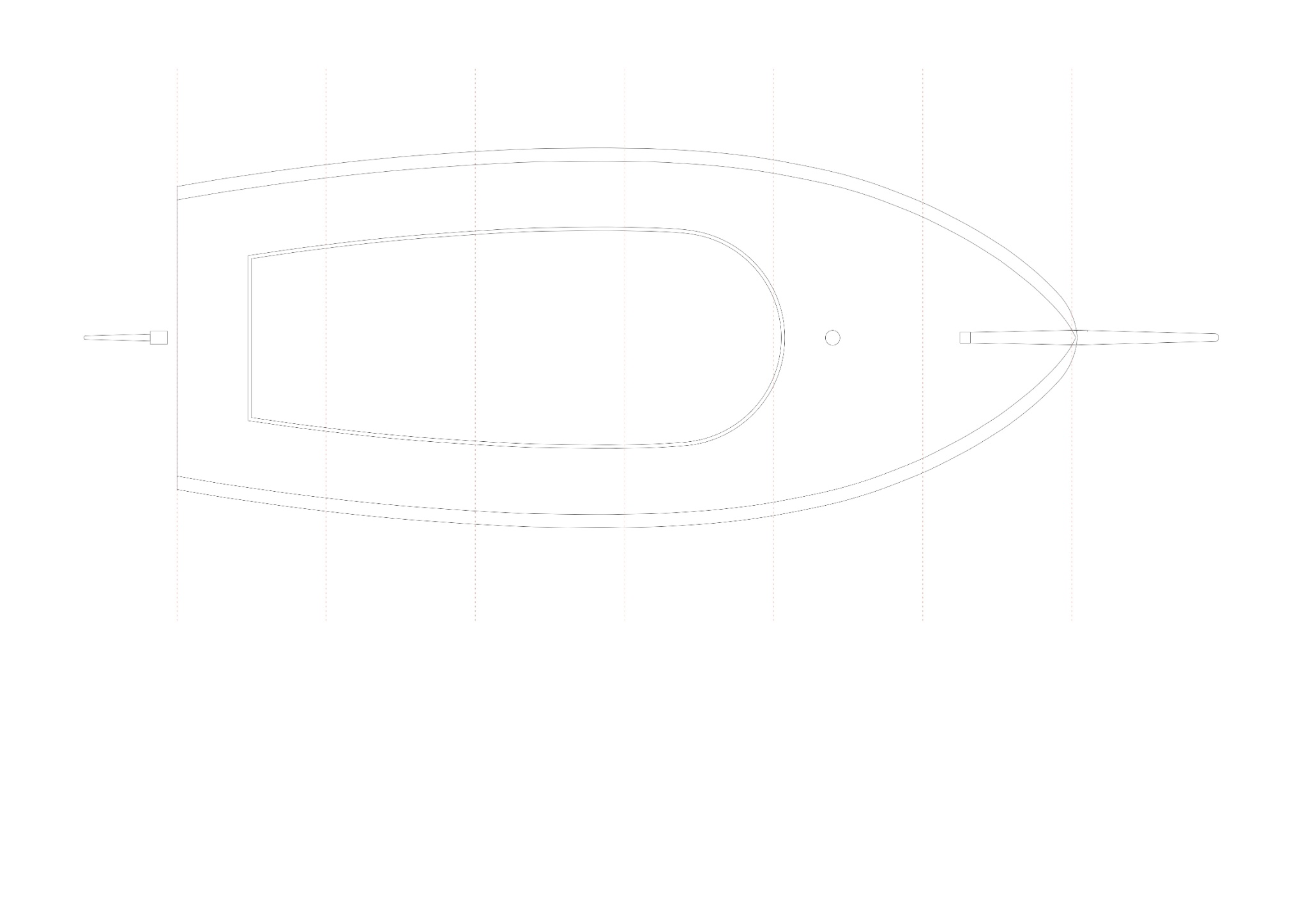
Using available information I've drawn up my estimate of the main parts of the Karoo. This is what I came up with, I've only drawn the details that I will be showing.
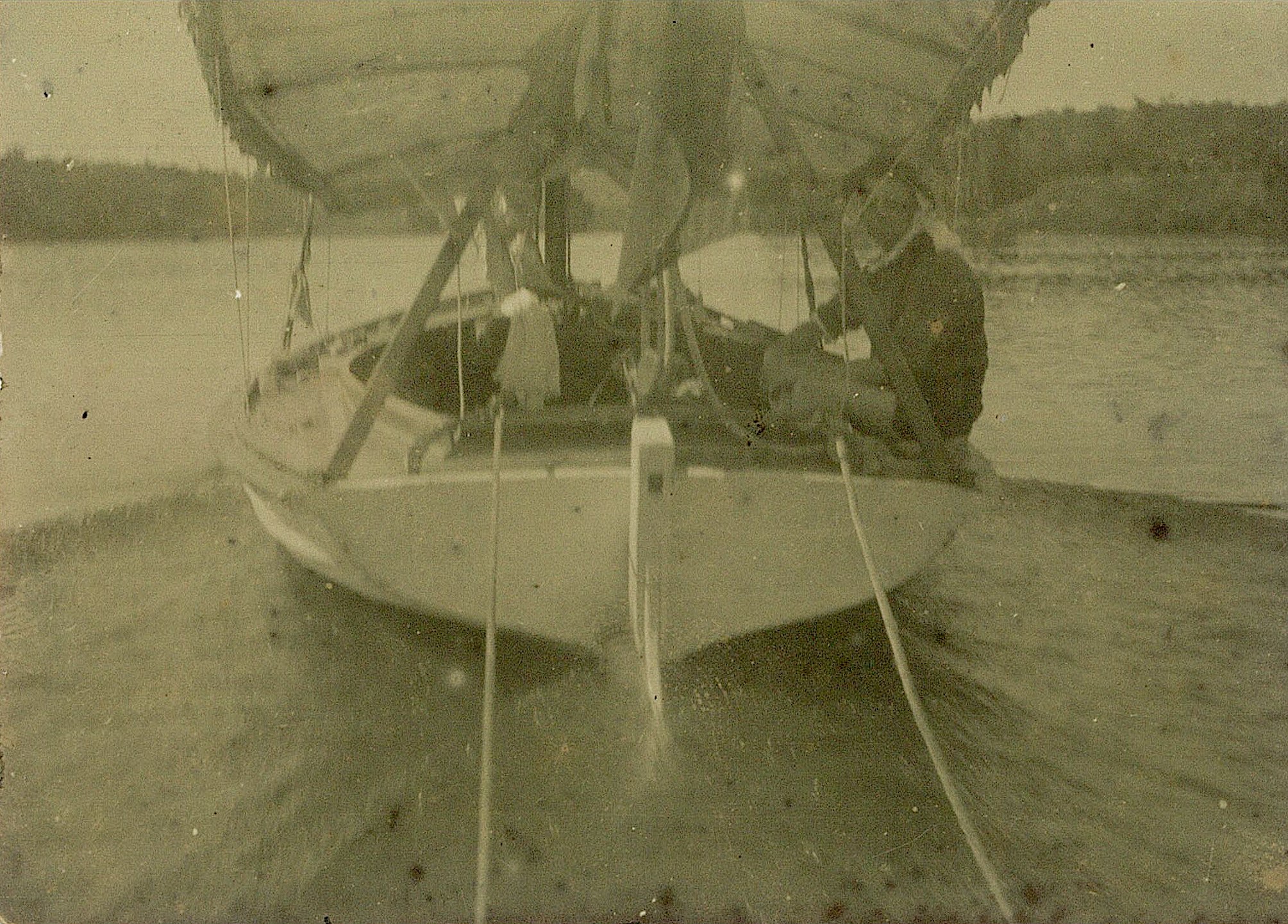
I used a mix of original Karoo photos & some of another notable open boat of a similar size & vintage, a locally very famous boat 'Vagabond'. There are very few, & not very detailed images of the Karoo, so I've relied quite a bit on the Vagabond images. The designer of Karoo had previously owned the Vagabond. There are many similarities, such as a short & slightly curved bowsprit, tall toerails with numerous drain holes
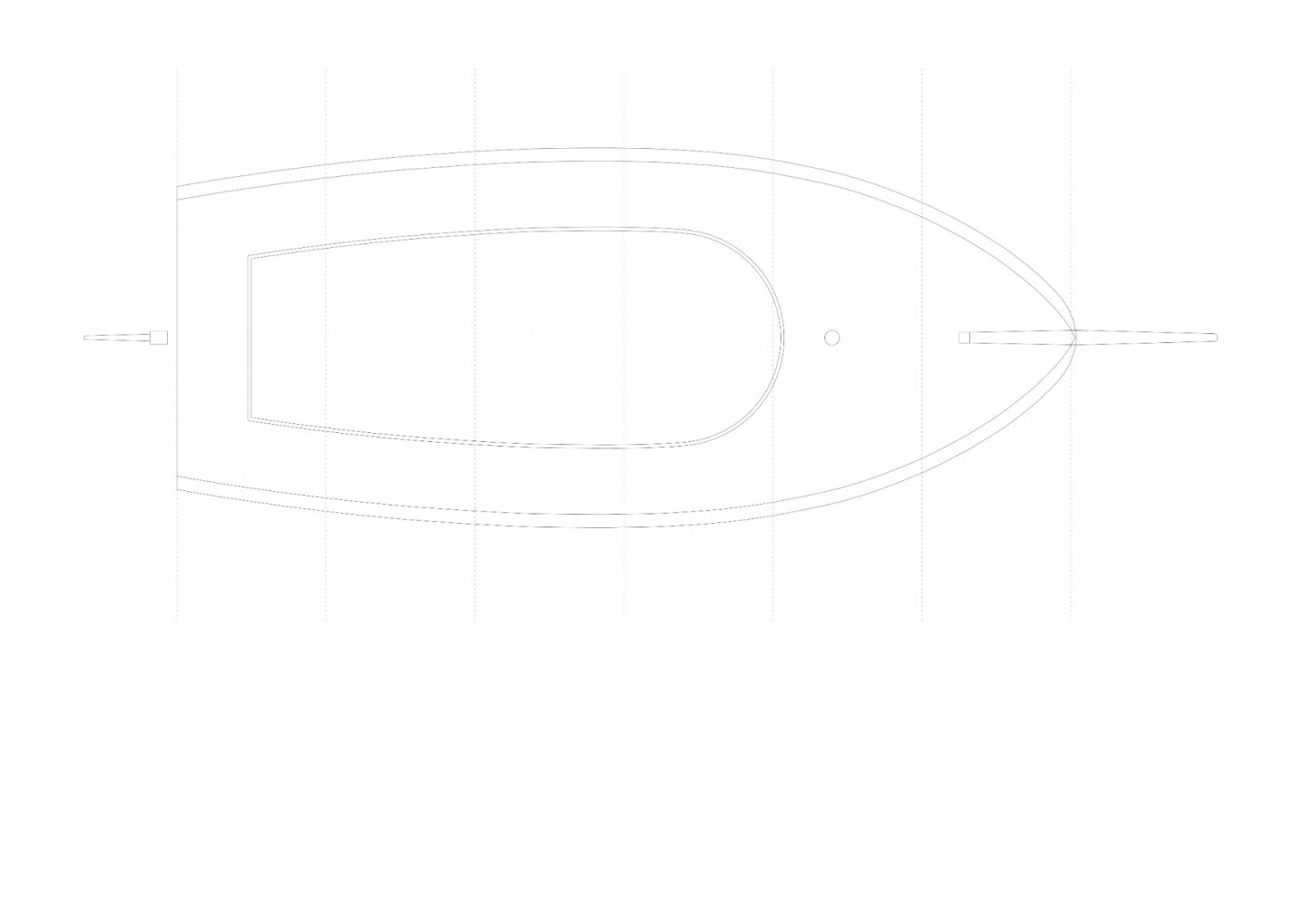
This stern shot of Karoo was useful to estimate the width of the side decks, the gunwale width, & the rudder, also the coaming height & shape.
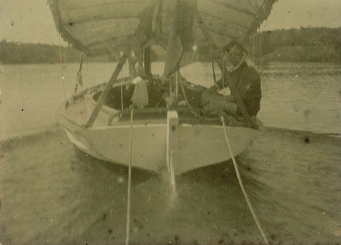
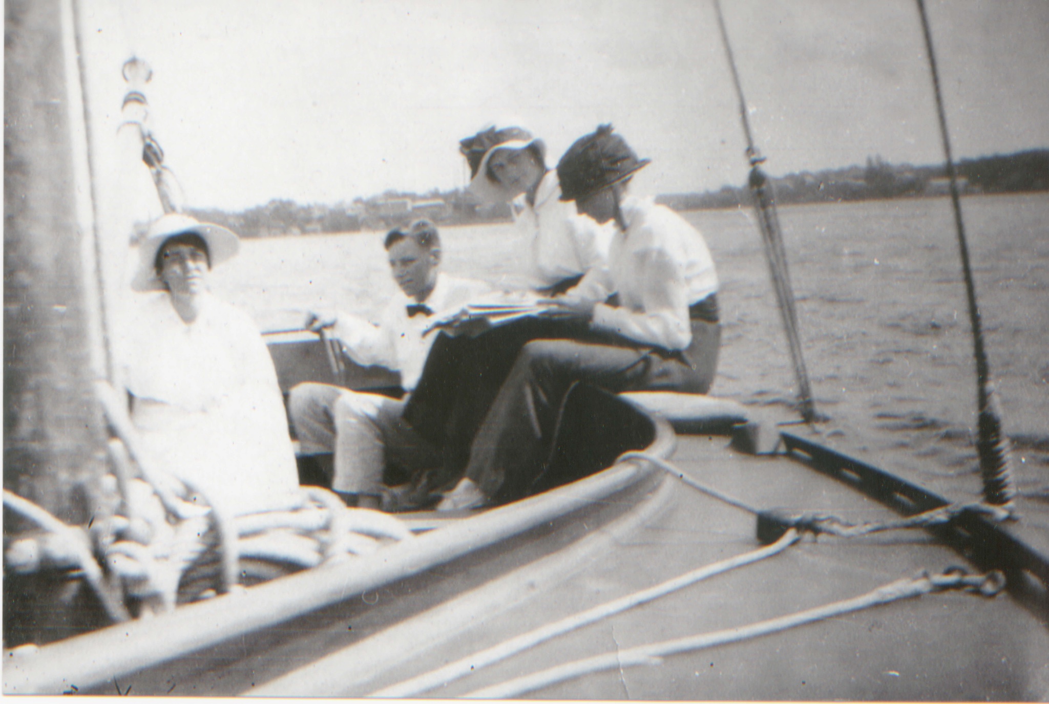
These shots of the Vagabond were useful to see various details, which helped to confirm various things
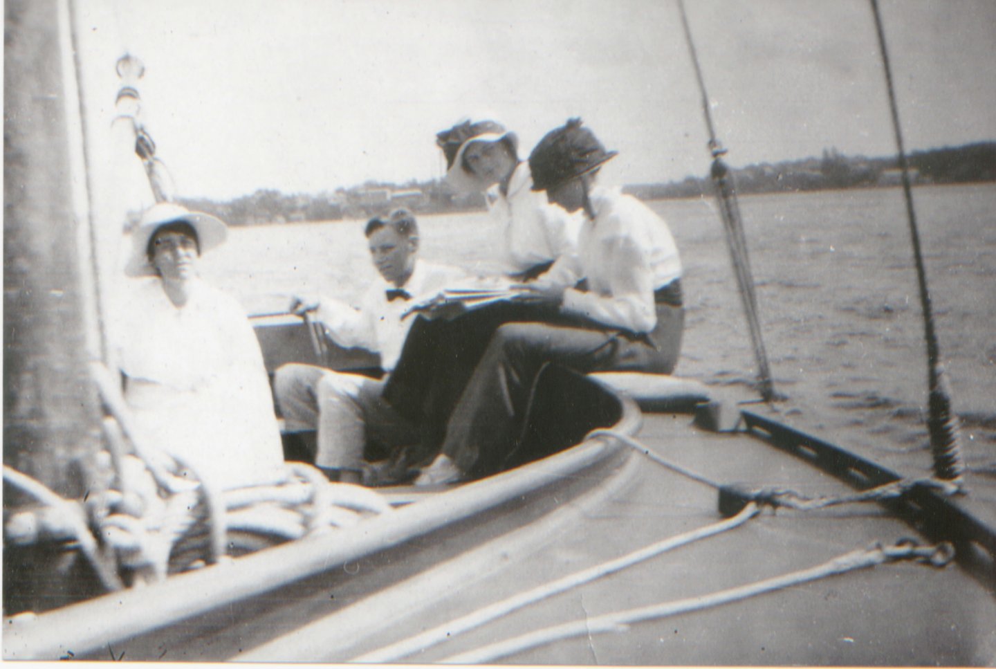

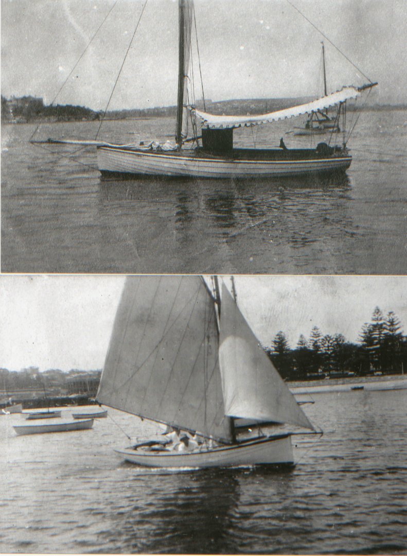
The last shot is a beauty, the Vagabond is such a pretty boat, & is still around.
I'm pretty happy with this plan setout, it "looks right" to my eye. I redid the top lift for the model & glued it to the second top one. I'll next scribe the cockpit opening onto that & cut it out.
all the best
Mark
-
Hi Vaddoc
Nicely done. It's a fascinating process, & also the slow reveal of the hull shape.
-
-
Thank you all, & especially Keith - fortunately I wasn't drinking anything when I read that.
Vaddoc, thank you - & one note on what you said: most boats built here at that time were done on a tight budget, & very few have exotic fitouts etc. The connection with what you said is that the bows & sterns are usually plumb - vertical. You get maximum boat for your timber that way.
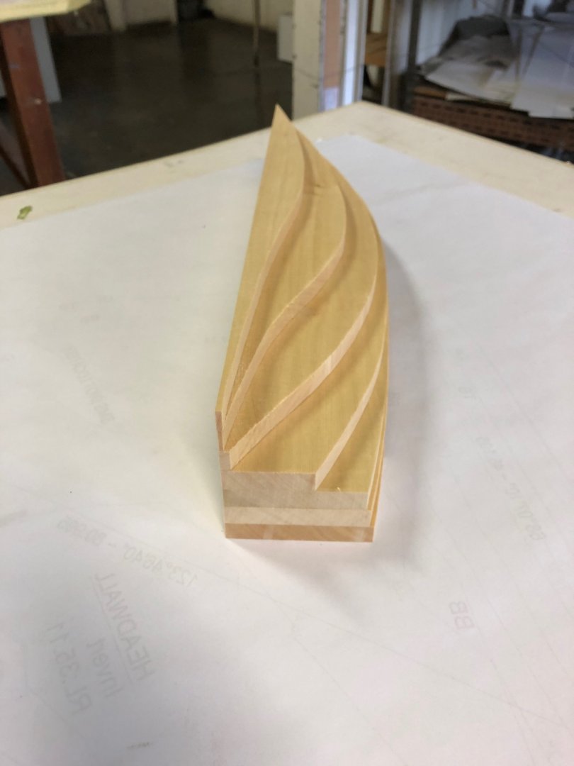
The 'lift' #6 (not sure if there's a technical name) needed to be corrected, as the previous post. I did that & also dropped the piece, so two minor repairs.
Below: the correction timber glued on, & the new ding on the bottom right, with a piece getting ready to be glued.

Below: now that's better. Transom pencilled on. Fascinating to see how slow Huon Pine grows. The lifts are about 12.5mm thick.
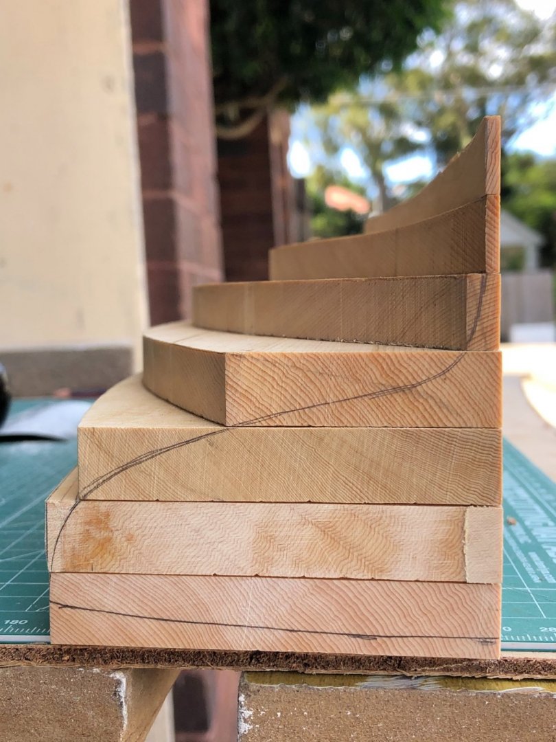
I am pencilling on all the positions of the mould, as shown on the drawings. So that when I'm rough shaping the lifts, I know if it's concave, convex or straight.

Before I start shaping them I need to try to setout the cockpit. I plan to show some basic details such as cockpit coaming, low part of the mast, rudder & tiller, gunwale. So, I'm going to hit the drawing board & see what I can work out - or guess - for the above.
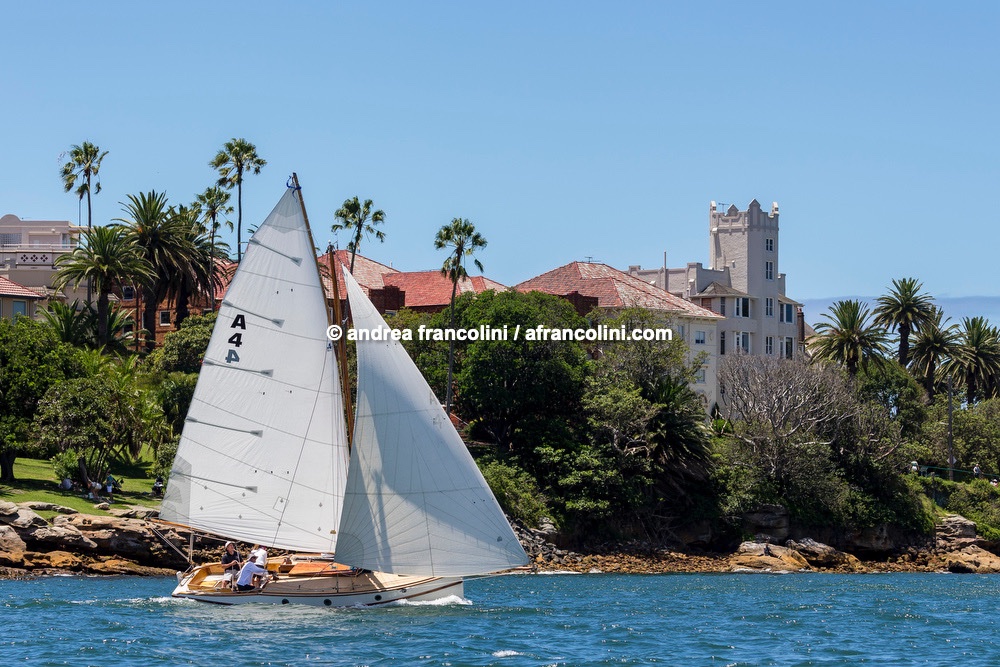
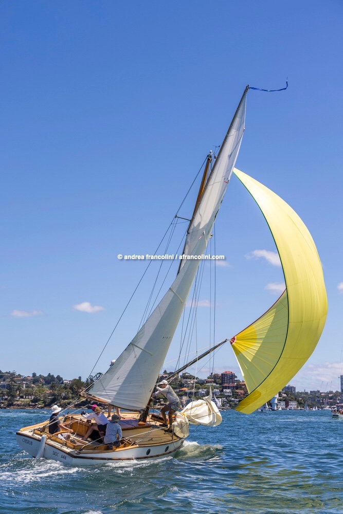
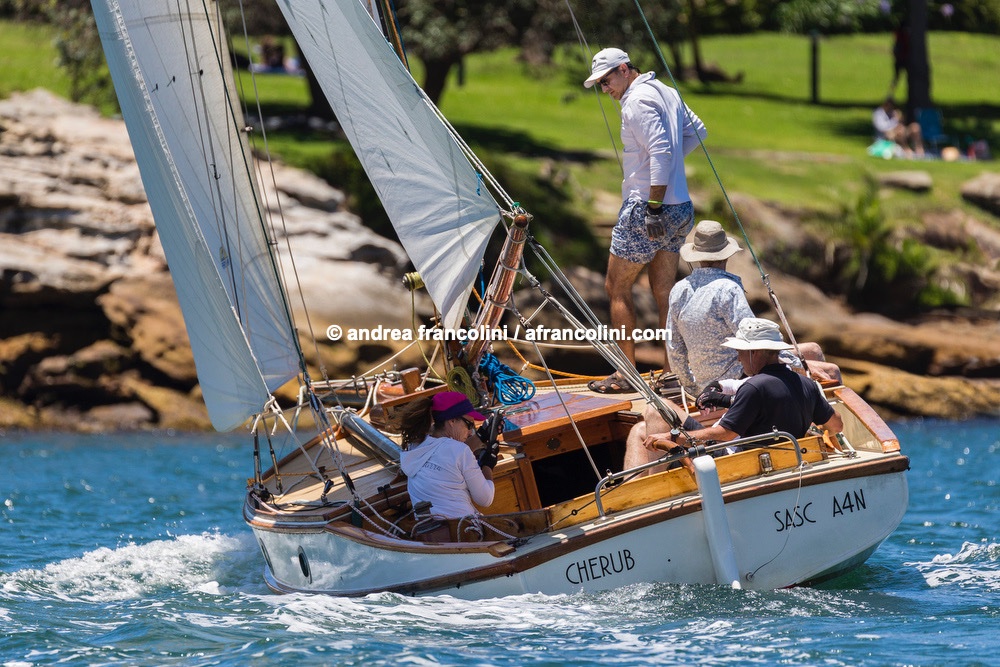
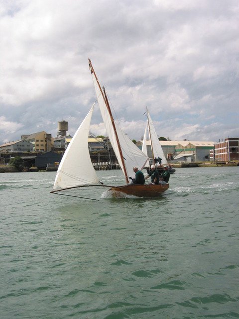
Lastly, a bloke in a RIB was following our sailing race in January & took some lovely shots of our 24' gaff sloop Cherub. Of interest to any boat lover, but in terms of this blog, it was also designed by the designer of Karoo & the next boat after Karoo. So, if you'll indulge me.....
Approaching the start line.
Struggling to control the spinnaker pole on a tight shy run.
Before the start.
- KeithAug, vaddoc, GrandpaPhil and 6 others
-
 9
9
-
-
I started to pencil on the mould locations on the timber lifts, to help when I do rough shaping, of whether the sanded shape is straight, convex or concave.
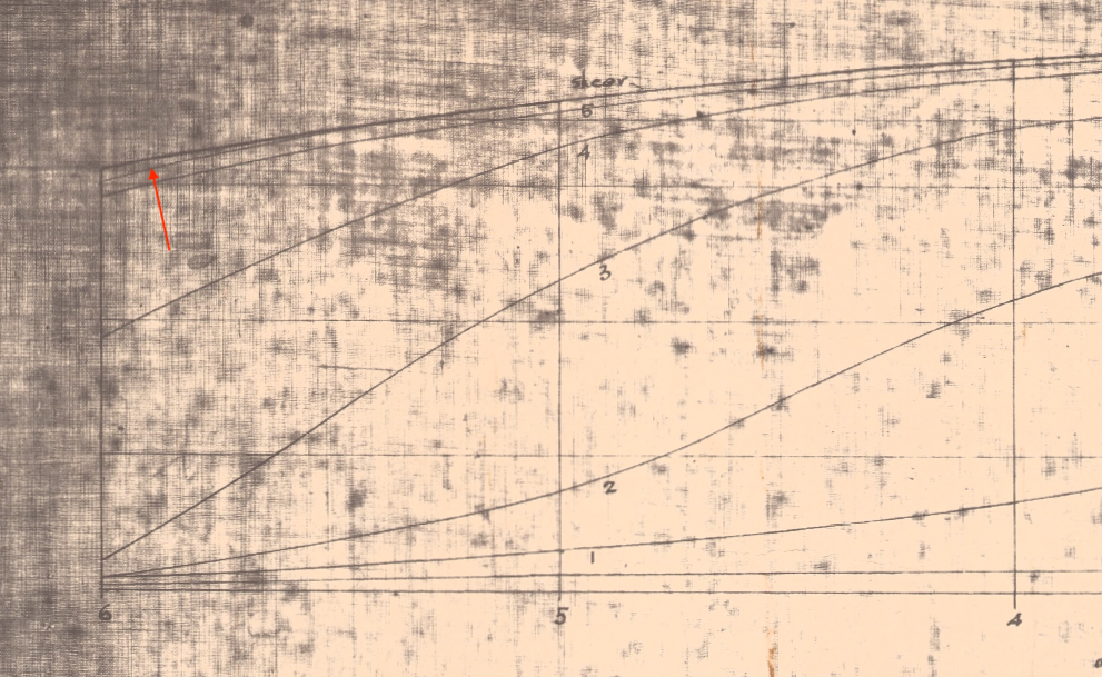
I picked up an inconsistency in the drawings. It goes to the issue of which drawing do you give priority to when there's a discrepancy? In this case its pretty easy, fortunately. Also the fix should be pretty straightforward.
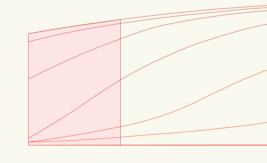
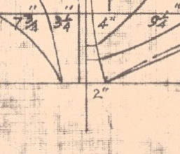
On the plans, this line was used to cut the the lift #6, it is the highest of the full length pieces. The red arrow points to it.
If you look at the transom, that line is pretty much vertically under the gunwale line. The small green circles show where the plan lines meet the transom. Numbers in red are the widths at 1:12 in mm.
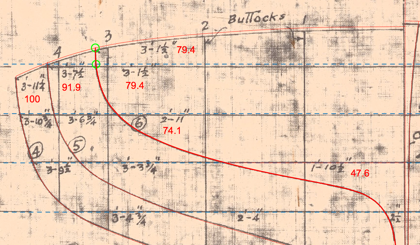
Here's where the transom shape would have to conform to, if I was following the plan lines.
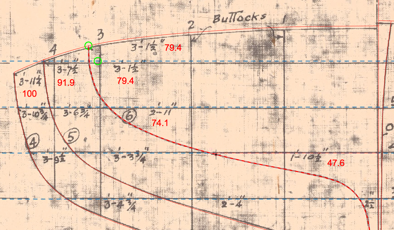
It's a lovely transom shape, it's an easy one. So, the plan lines will be adjusted to suit, as below, ie: following the gunwale. The pink is the shape of the top lift at the stern.
Good news is that I kept all the timber offcuts, & I won't recut the whole piece, I'm going to carefully add timber from the offcut.
-
Hi Rich
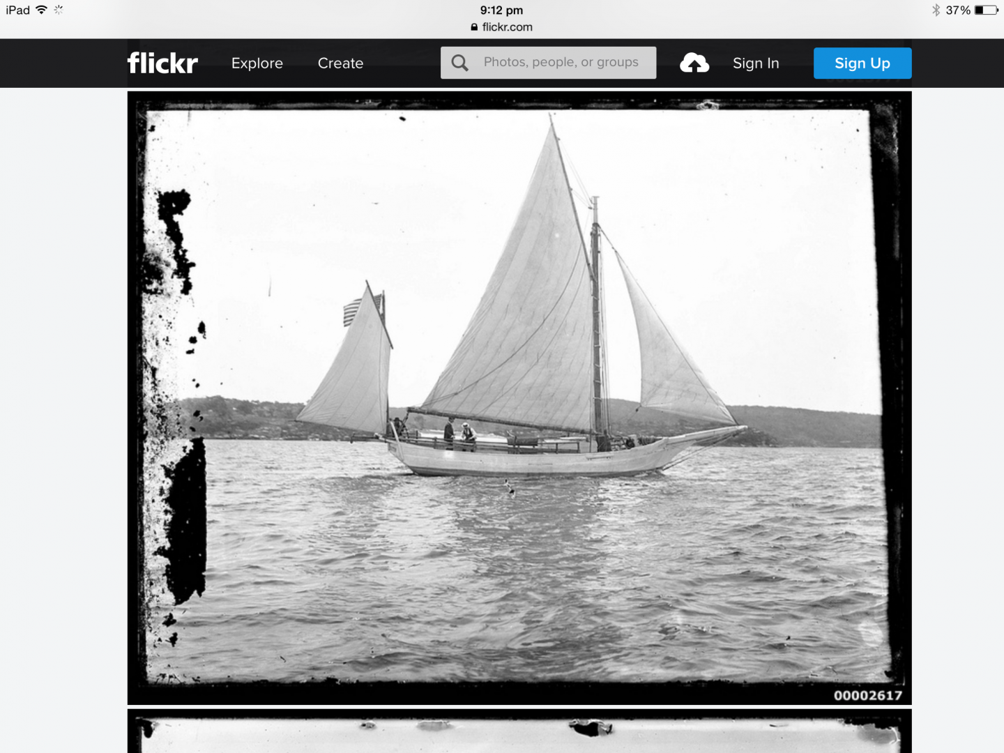
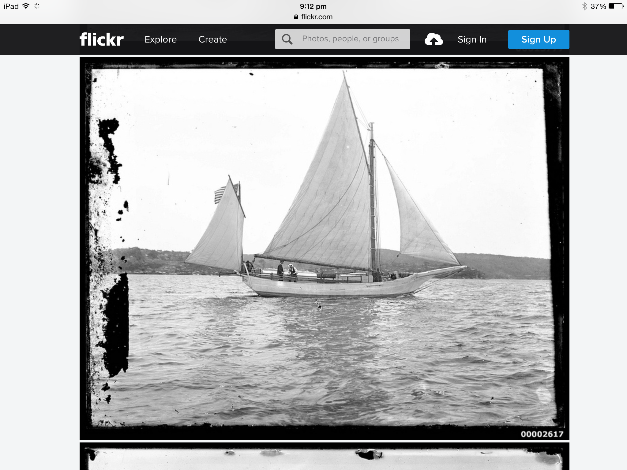
I'll attach a photo below from when the Spray was in Sydney. The photo has quite good detail, I hope it's interesting if not actually useful. I believe he was given new sails here & these do look pretty good.
As an aside, our sailing club has a "Captain Slocum Trophy Race", the connection is that a member of the club was thought to be the first person aboard the Spray in Sydney. When he was about 10 & was fishing with friends near the heads when an unknown boat came in. They rowed over & went aboard. I am friends with the son of that boy, the son is now around 95 - at the last count.....
Mark
-
-
Hi Carl
Sorry for the slow response - golly it's been a long time since I was here last. Yes, this boat has swing centreboard & it's just visible in the photo in post #29. I don't have the open boat book, so I'm not sure on the reference, but in this case (which is typical of a pre-1940 centreboarder) there would be a removable pin at the forward end of the centreboard case as a pivot. The front of the plate is usually straight & the aft edge curved.
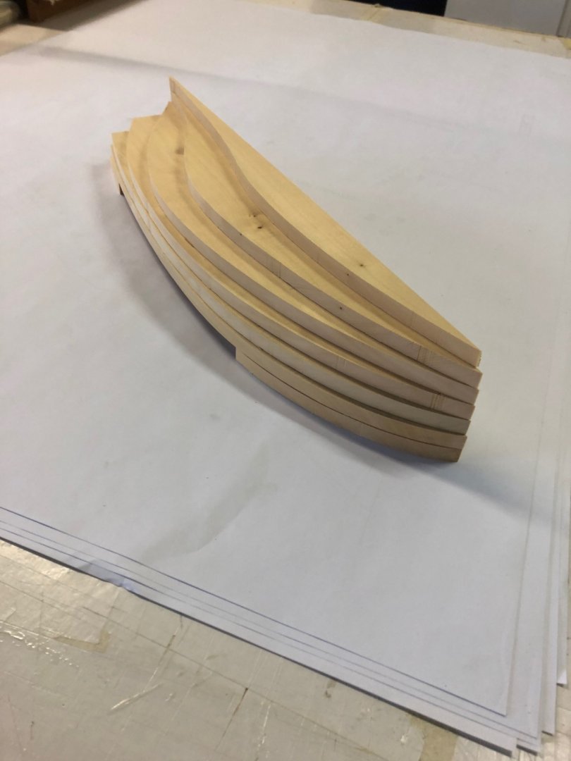
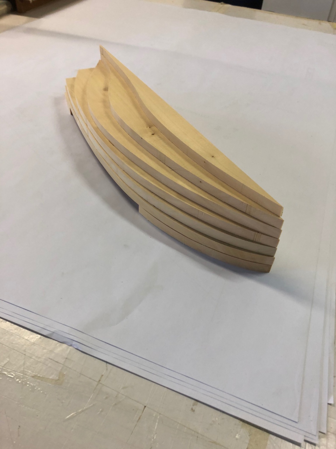
I have made some progress: purchased timber, scribed the cutting lines & cut them out. I was considering planking over a solid model, but decided against it. So the timber is cut to suit the final size.
I tried to get King Billy Pine, a Tasmanian Pine variety that is light weight & straight grained - but my local timber specialist didn't have it so I have used Huon Pine. The timber is a nice pale toast colour & will become a honey brown over time.
The next step is to scribe cutting lines on the timber & then do some rough shaping before gluing the pieces (lifts?) together.
Best wishes everyone.

-
Hi Stephen
I haven't been following for a few months - & it's a pleasure to see your finished model. It's ravishing. The use of marble for the base is beautiful & the case is clever & enlivens the entire effect. I've gained from following the build.
Mark
- Louie da fly, mtaylor and Keith Black
-
3
-
Hi Stephen
I have a couple of comments, hopefully they might be useful. But they wouldn't affect the rigging so much as giving alternative ideas on how they might have worked with a simple rig that has limitations:
Given what you say about the stability of these vessels, it is a possibility that they did not gybe the sails. It is a tricky manoeuvre even in a little dinghy, let alone such a large sail area & a tender boat. It sounds like a possibility that for them, sailing meant heading downwind or within maybe 5-10º off the wind, & to make any angle to the wind they dropped the sails - or a slight angle with no gybing. Why risk it all with a gybe?
Or - for one gybe they hoisted one of the sails (port tack, say). If they wanted to change angle to the wind, they dropped that sail & hoisted the other one.
Or - looking at you sail plan, I would think they could gybe the foresail on deck - drop it & carry the spar & sail aft, around the mast & forwards again. It would be pretty easy with all that labour on tap.
- mtaylor and Keith Black
-
2
-
Bravo Stephen, looks amazing.
It would still be possible to use the new figures - they could be trimming a sheet.
- Keith Black, cog and Louie da fly
-
3
-
-
6 hours ago, cog said:
Does she have a fin you can lift?
Hi Carl, yes there's a centreboard for certain - but a boat like Karoo would be pivoting & not lifting like the skiffs.
-
Hi Vaddoc
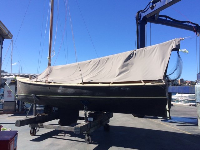
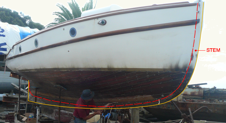
I was wondering what video was in store for us - it was the Brit! I've sailed a couple of times as main sheet hand on this boat, it was fun & hard work. But she actually does have keel timbers below the rabbet line, although not much at all. Otherwise there would be nothing for the bottom edge of the garboard to sit against. There's a deadwood aft, but again not large. I think Karoo probably had a more of both than Brittania, but maybe not much. If you see how the lines drawing of Karoo shows the lowest line parallel with the waterline, that was another clue - you would expect the deadwood to slope downwards towards the stern, as in the profile photo below (Karoo replica being repainted) you can see the boat gets slightly deeper as you go to the stern.
- cog, GrandpaPhil, KeithAug and 3 others
-
6
-
Hi Vaddoc
The clues are in the drawings. In the body plan, the detail below shows the curved line of the planking stopping at a horizontal line, not faired into a deadwood or keel.
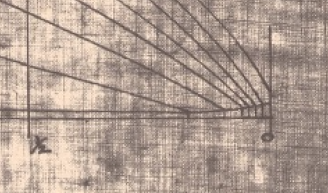
It's probably clearer in the plan view of the lines, below. At the bow the hull lines do not show the pointed or rounded shape of a stem, they lines stop where the planking would meet the stem. The lines resolve as a line perpendicular to the centreline, not the smooth resolved shape of a stem profile.
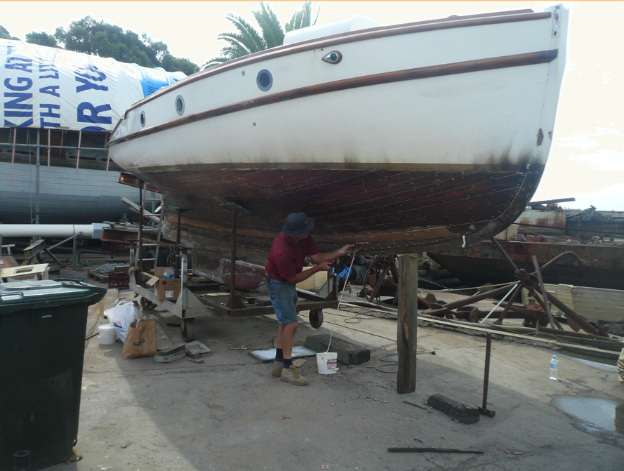
Below you can see the planking & stem & keel clearly with he paint removed. The second photo shows the rabbet line in dashed red; the yellow ochre line shows the hull profile if it was a centreboarder like Karoo(ie: no ballasted keel below the deadwood). I think the lines show the red dashed line, & left the rest to be resolved during construction.
- mtaylor, GrandpaPhil and KeithAug
-
3
-
-
-
-
Hi Carl, Vaddoc, others
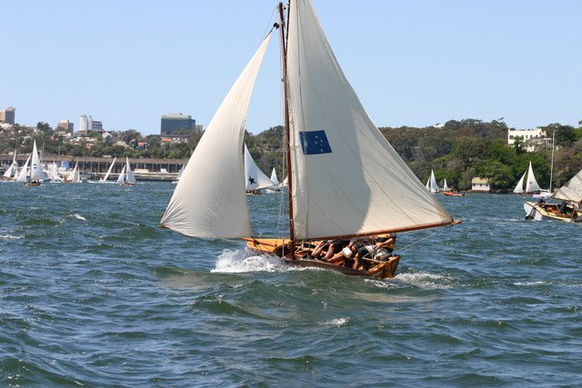
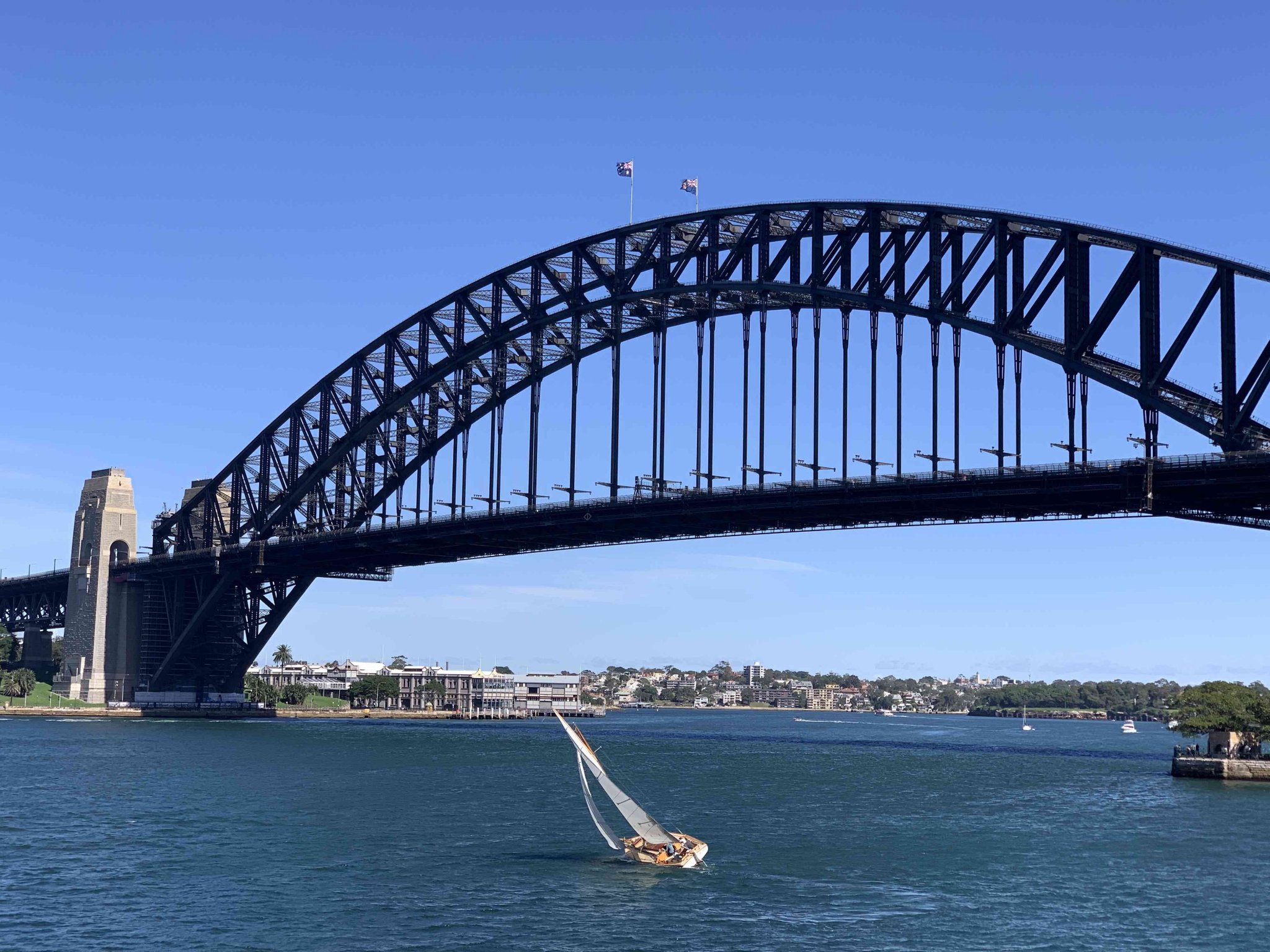
Thank you for your concern & I'm very happy to say that I'm mainly well - apart from a heavy snow-skiing fall 2 weeks ago. Neither arm is up to sailing at the moment, but with the Spring sailing season soon I'll be ready for that. In their eternal wisdom our government decided that sailing & fishing were forms of exercise & so we did plenty of both during the worst of the lockdown in Sydney, the remarkable photo below was taken by a friend - us on a family outing one autumn day on an almost empty harbour.

The half model is going slow. The thing I've been researching is to confirm that the outside line on the sheer plan (on the drawings above) is the rabbet line ie: does not include stem or keel timbers. I borrowed a half model of the Yeromais (copy of Karoo, slightly revised bow lines), below. It's been made to the rabbet line, I think.
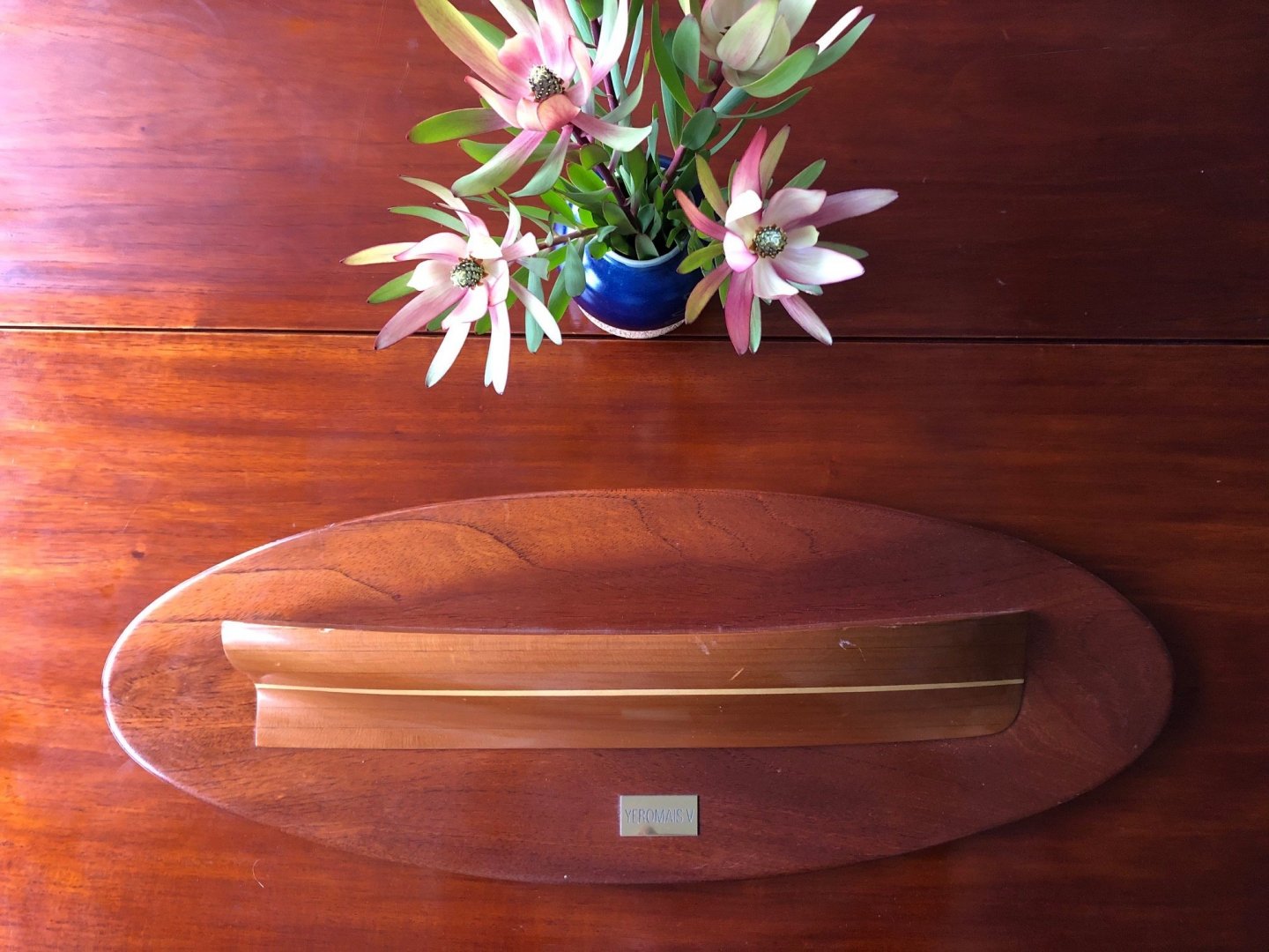
I'm not ready to start building, but the prep is ticking over. I'm considering a planked half model, so the stem & keel timbers would be separately visible. I want to be sure it's correct, history can be based on errors. I've been able to get some poor photos of the Karoo as she is now, I've yet to do a close examination of them, but I believe they support my thoughts. I hope to visit her soon, when Karoo is next slipped, so I can take some dimensions etc. It's a couple of hours north of here at Lake Macquarie, she's been covered to a motor boat used as a starter boat for sailing clubs over the last 30 or 40 years.
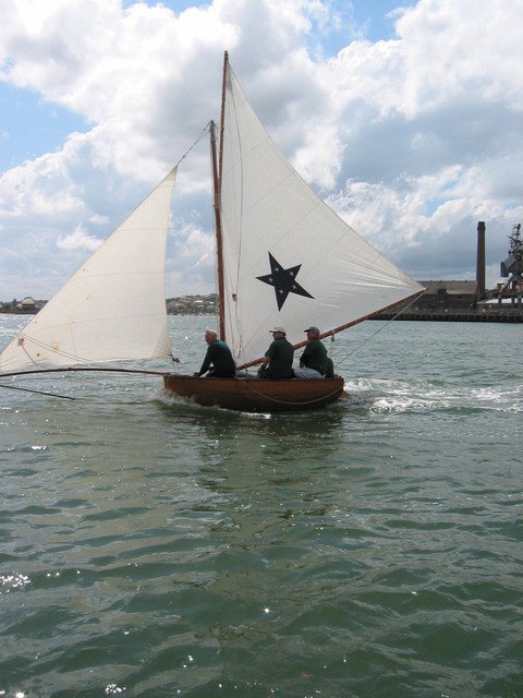
Little bit more on the "beam" discussion - Vaddoc you will be interested to hear what I read: in the early 1900s Cliff Gale (designer of Karoo), raced on a lot of smaller skiffs, one of which was in the 10' class. They would now be called an "unlimited" class, so no limit to the sail area; the one rule was that the hull itself could only be 10' long. This boat had a 10' beam, so as wide as it was long....sounds impossible, & it was difficult to build. I will copy recent photos of 10 footers, the beam works because the hulls are shallow - hence "skiff". It doesn't look crowded, but 3 or 4 men in 3.1m is pretty tight. I would guess these are 2.5m beam. (my boat is visible behind in one, the pale grey stern)
- BANYAN, mtaylor, GrandpaPhil and 3 others
-
6
-
Hi Vaddoc,
This has been fun. The model is lovely & you've been very inventive in how you approached the technical aspects.
- FriedClams, mtaylor, Moab and 2 others
-
5
-
There's a realistic sense in the variety of postures, hair, skin colour, seating position etc. It's looking very good.
- Louie da fly, druxey, cog and 1 other
-
4
-


Royal Caroline by Bedford - Panart - 1/48
in - Kit build logs for subjects built from 1501 - 1750
Posted
Hi Steve
Best wishes for this build, the connection to your daughter will no doubt make it a powerful time.
I will be following this with great interest. What period was the ship?
Mark