

Mark Pearse
-
Posts
698 -
Joined
-
Last visited
Content Type
Profiles
Forums
Gallery
Events
Posts posted by Mark Pearse
-
-
Hi Steven
Just catching up on models - & wow, what an extraordinary craft. I'll read your introduction, I'm sure there's some information on her there.
- mtaylor and Keith Black
-
 2
2
-
Hello Håkån
I've enjoyed this journey very much, it's a beautiful model. I'm sure it would be a lovely boat to sail on.
- Wintergreen and mtaylor
-
2
-
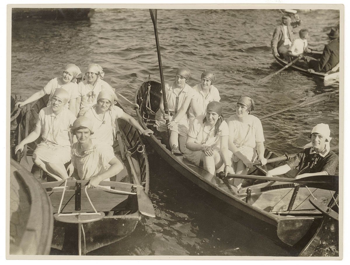
Hi Druxey
I came across this lovely image of women's rowing teams in Sydney approx 1900-20, with the steering yoke pretty much as your craft, & showing how they worked. Amazing how close the designs are.
- Keith Black, mtaylor, AON and 5 others
-
8
-
Hi Gary
Very enjoyable to follow along, & an especially lovely result.
Could you explain the 1:87 scale?
thanks
- Edwardkenway, Old Collingwood, Canute and 7 others
-
9
-
 1
1
-
Great news Steve, that looks great; I reckon there's flathead out there too, warm water & sand bottom...
- EJ_L, Bedford and Keith Black
-
3
-
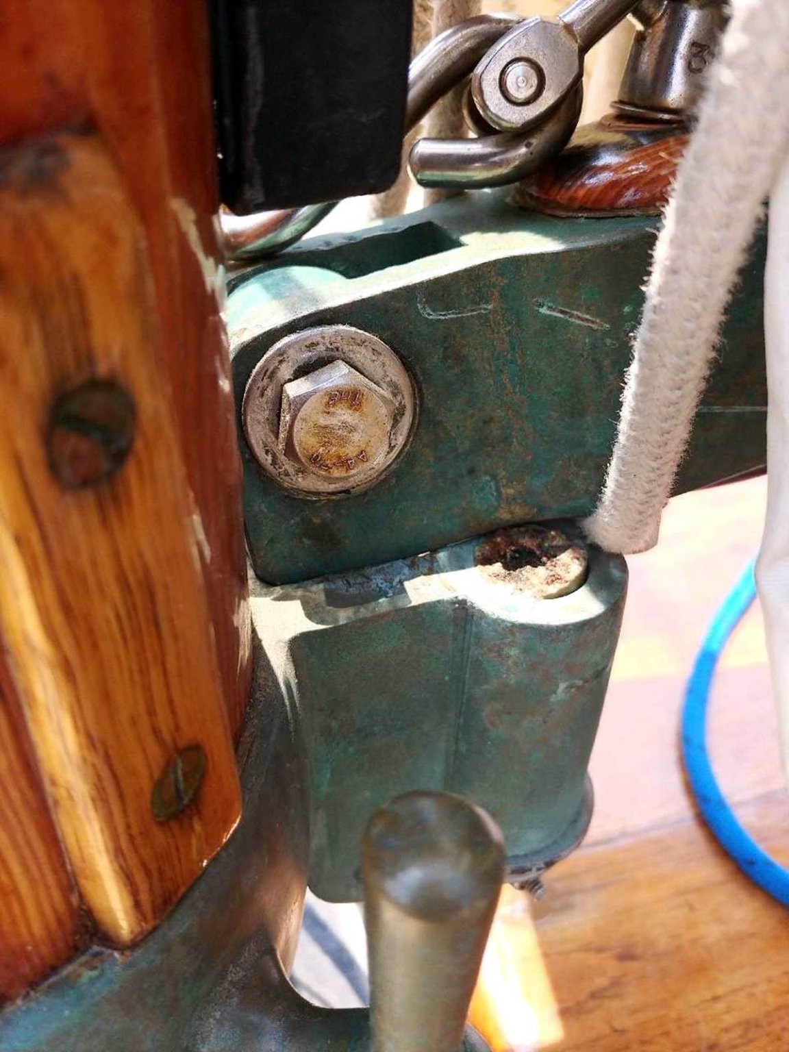
Hi Keith
The foremast one is curious. However, it does look like (from the initial photos) that the foremain might be loose footed & the main main laced. Moving the gooseneck pivot point aft would mean the sail foot automatically loosens when the boom is eased out (good), but wouldn't make a difference if the foot was laced. So that's a possibility. The only thing I know for sure is that a gaff main puts a huge load on the gooseneck fitting, having broken two 7/8" solid bronze gooseneck pins, with a comparatively small 24' hull, see results below...

-
10 hours ago, KeithAug said:
The equivalent fitting on the fore mast has a horizontal axis for the hinge unlike the main mast which is vertical.
Hi Keith, do you have a detail photo?
- Keith Black, mtaylor and KeithAug
-
3
-
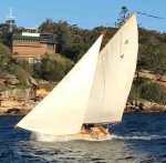
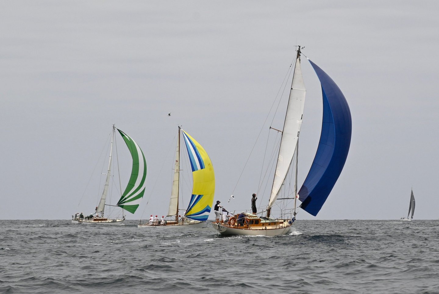
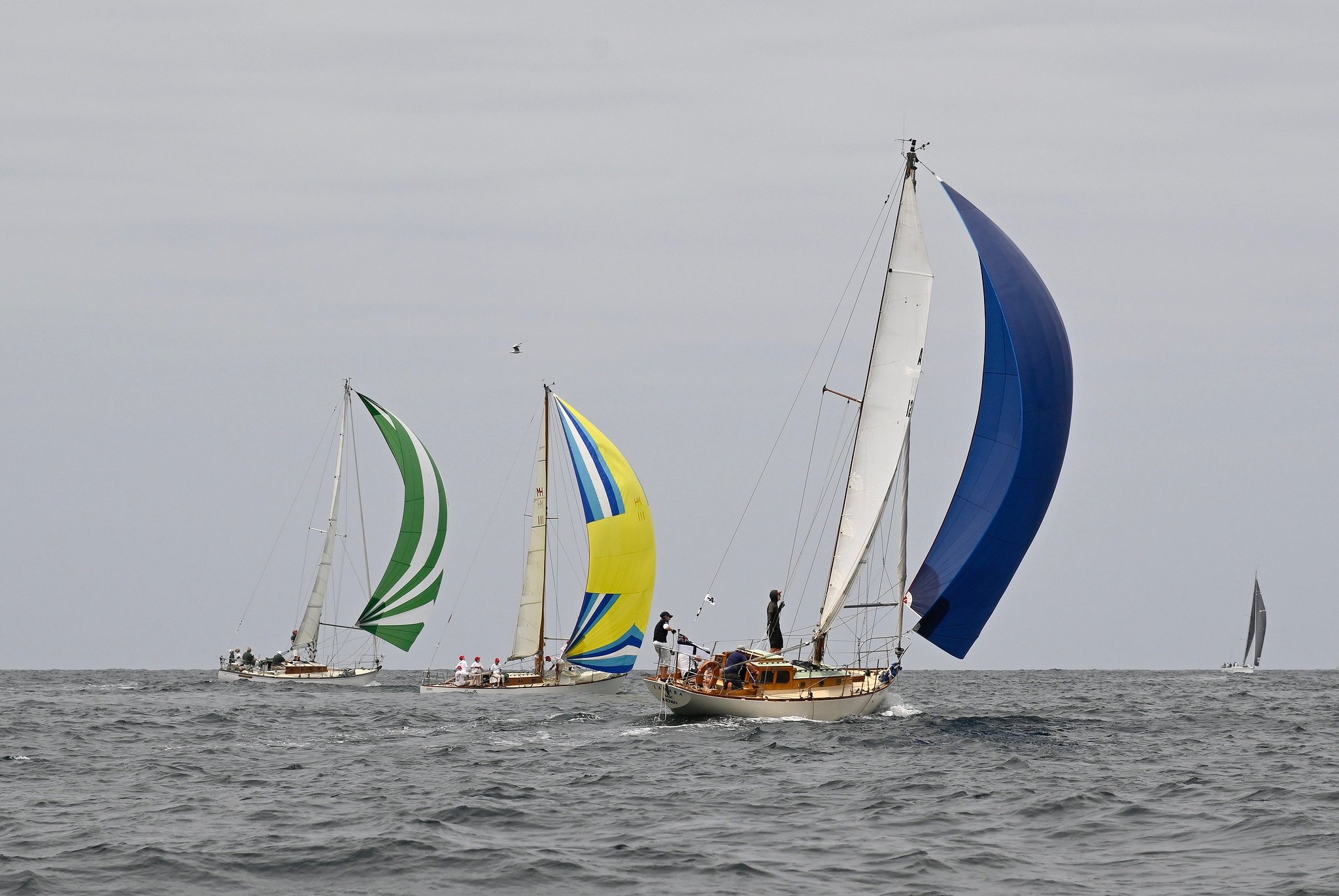
that's great news Steve.
Look out for my mate Mike & his Jock Muir yacht Lahara A121, the blue spinnaker (pale green coachhouse roof is easy to recognise). I'm not sure where she is moored.
- GrandpaPhil, Keith Black, Bedford and 1 other
-
4
-
You've done a wonderful job. An interesting boat, a couple of things are especially interesting: With the person in the model for scale you realise just how big the boat is, especially the rudder & tiller arm are huge; also it's interesting how high the freeboard is.
I'd love to go for a sail on that!
-
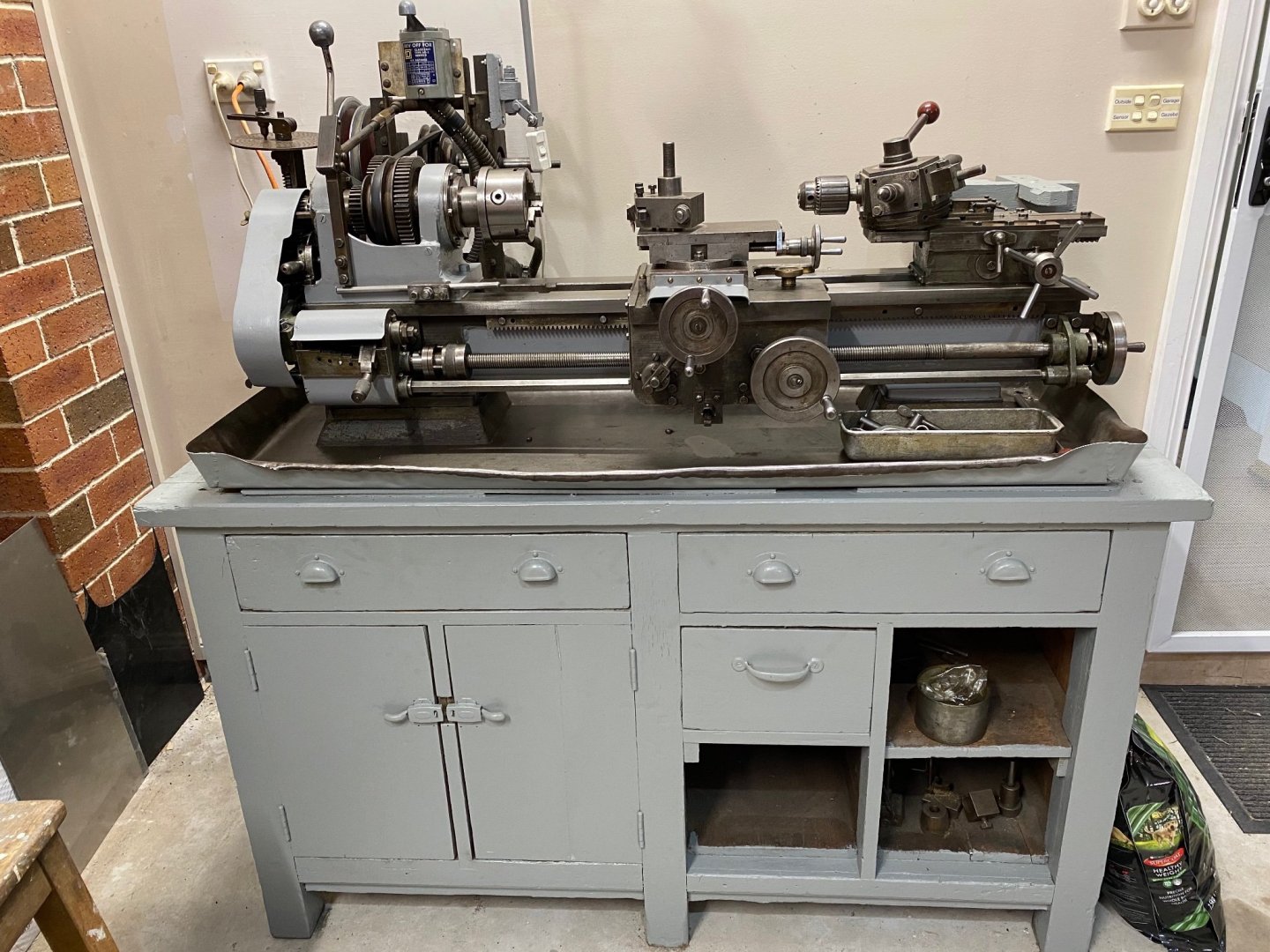
13 hours ago, michael mott said:
So what am I missing here?
As you asked: I think this will interest you Michael, a mate's grandfather built this lathe in the '30s; his father (now 90) inherited it & built 8 working steam scale locomotives & numerous stationary & traction engines with it. It's just been restored by my friend's brother - what a good story.
-
Best of luck with that Steve.
Is it inland, Orange / Bathurst area? We had sheep & cattle between Oberon & Bathurst when I was a kid, so that area is close to my heart.
- Cathead, Keith Black and EJ_L
-
3
-
-
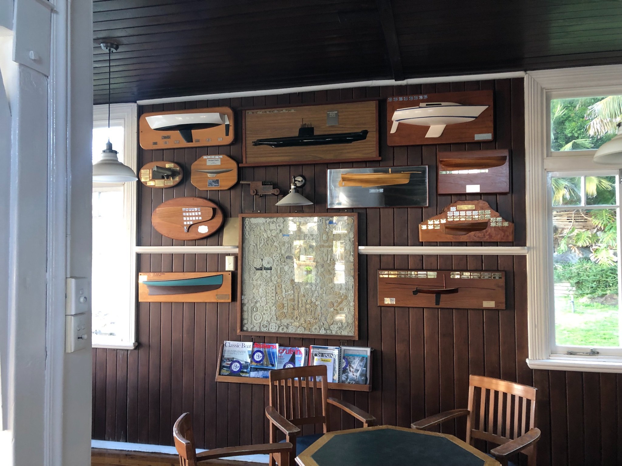
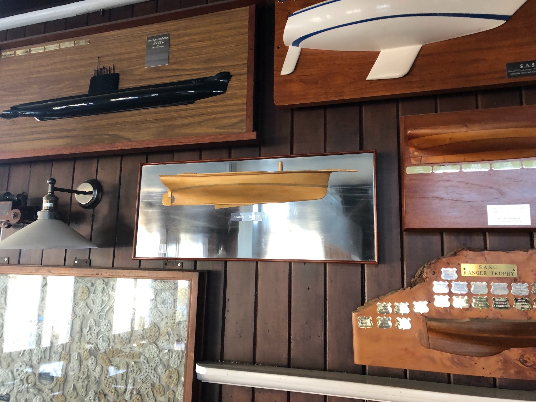
Hi Pat
Ha! Yes the submarine 'Platypus Trophy' is a curious one for a sailing club. I don't recall what the connection is....
A couple of the grander sailing clubs have some very nice models - if you're in town, The Squadron (Royal Sydney Yacht Squadron) & CYC (Cruising Yacht Club of Australia), up in Pittwater the Royal Motor Yacht Club - they all have great collections. Notable is the CYC's half model of every handicap winner of the Hobart.
-
-
-
-
-
On 7/1/2021 at 5:39 PM, silverman834 said:
I used dry heat to bend the keel plank
Hi Silverman.
Nice clean work there. I also used dry heat to bend timber, mainly with a hot air gun. I did use boiling water once because it had to be softened along it's full length at once - but I don't think the timber was more flexible from that technique than just dry heat. For planks I would look at the twist required & then clamp one end of the plank, then apply hot air & twist the timber with the other hand...let cool & check...twist some more etc.
Mark
-
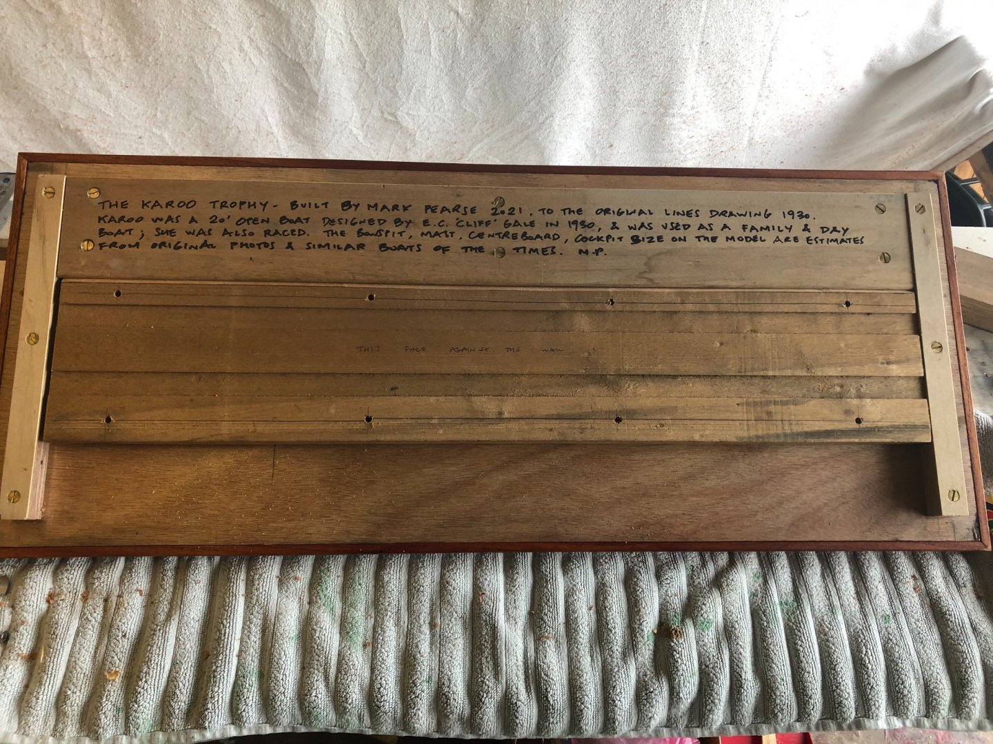
Thanks everyone
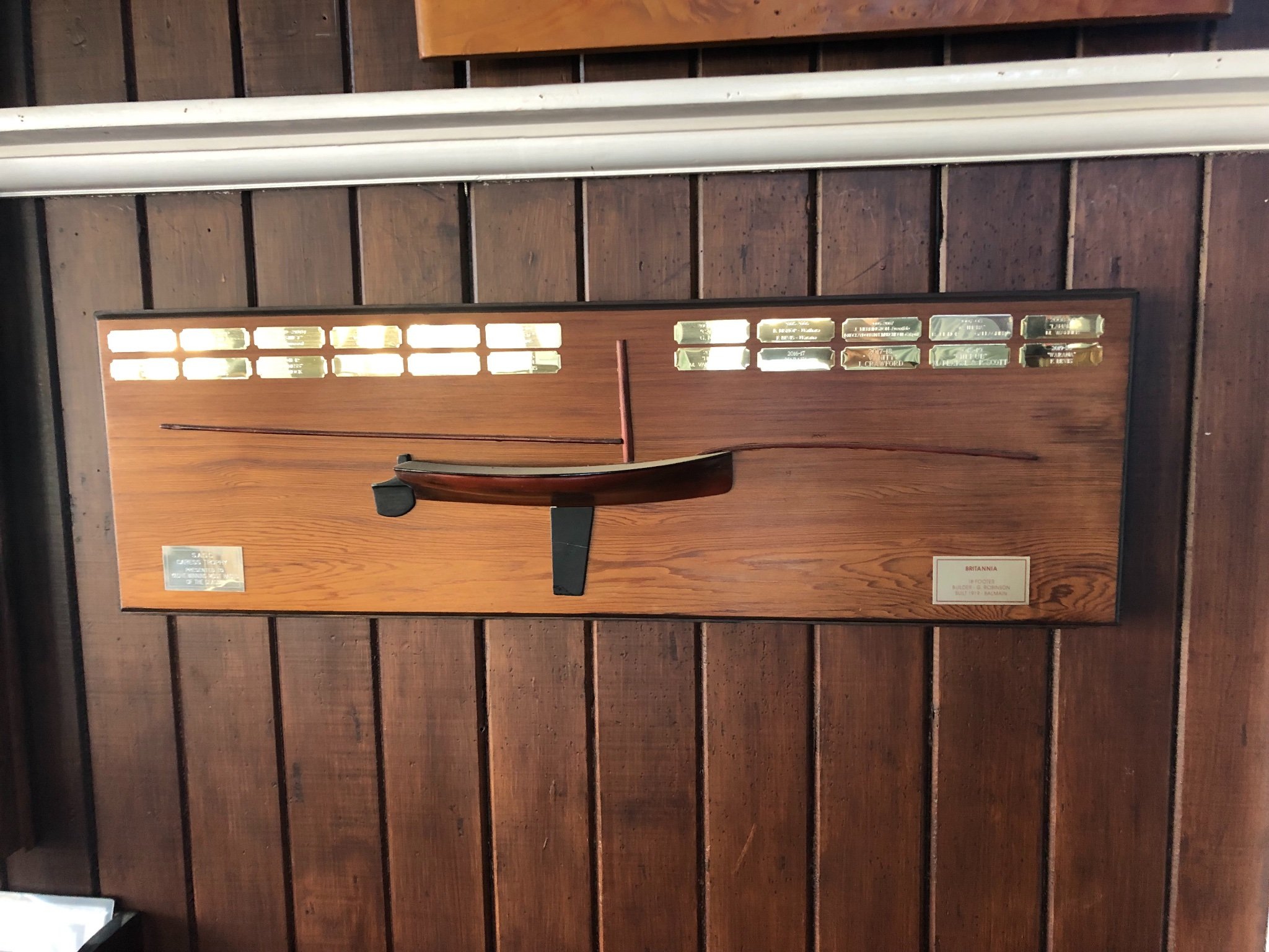
Hi Druxey, I proposed this Trophy (most sailing clubs have a lot of trophies, so additional ones are not always welcomed) to encourage classic yachts from other clubs to sail with us (The Sydney Amateur Sailing Club). We have a Sunday non-spinnaker classics series, & one race from this series becomes an 'invitational' race, so open to casual entries from anyone. To make it more interesting a bottle of whisky & your name on the trophy are both on offer - so at the annual prize giving day you get to have the trophy on your table & take the whisky home. It's pretty amazing what people will do for a bottle of whisky & some sparkly silverware, but it's all part of the fun.
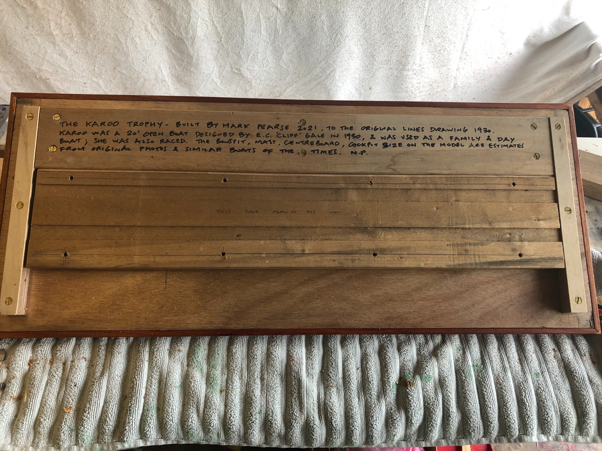
When the trophy is up on the wall, I'll post a picture of it.
-
I wonder if they used the yoke to lock the rudder off while rowing, & used it for steering only while sailing. Wefalck seemed to be pointing to this.
- thibaultron and Keith Black
-
2
-
Hi Roger,
Good question, & the answer is a bit long perhaps.....I decided to do that cutaway for the propeller when, fairly late in the build, I looked back at the drawings & saw that the cutaway is shown. So although parts of the boat as shown are speculative (the drawing doesn’t show the rig, cockpit aperture, rudder/tiller or centreboard), I wanted the hull to be as accurate to the design as I could make it. If the model is for myself I could do what I wanted - but in this case the model will be with other half models on a wall of our sailing club, where the designer was a member for most of his life. So, I have been mindful of the place of a model to be a kind of history. Few people will take the trouble to look at the drawings but lots will see the model. It’s a minor detail, but I was swayed by the knowledge that having it the same size & shape as the drawing would be an indicator of the effort to be accurate in the hull.
-
many thanks Vaddoc
and best wishes for your two current builds.
-
-
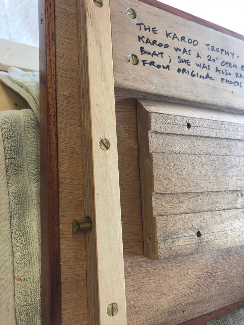
thanks everyone
I completed the supports this morning - if you want more details there was a post that sketched the design. The photos below show if from the wall point of view. The wall plate is the lower split batten, pre=drilled for up to 8 fixings. The weight of the model is held by this. The model is dropped onto the wall plate, then the side screws, visible below, are put in. They really stop it from being accidentally bumped off, or the opportunistic thief (that isn't carrying a large flat head screwdriver....)
- GrandpaPhil and druxey
-
2


Schooner Germania (Nova) by KeithAug - FINISHED - Scale 1:36 - 1908 / 2011
in - Build logs for subjects built 1901 - Present Day
Posted
Hi Keith
Possibly the large bilge keels are to reduce wallowing. For this launch, drying on a mud or sand bank doesn't seem as likely.
Thanks for the ongoing detailed posts on how you make things.