usedtosail
-
Posts
2,424 -
Joined
-
Last visited
Content Type
Profiles
Forums
Gallery
Events
Everything posted by usedtosail
-
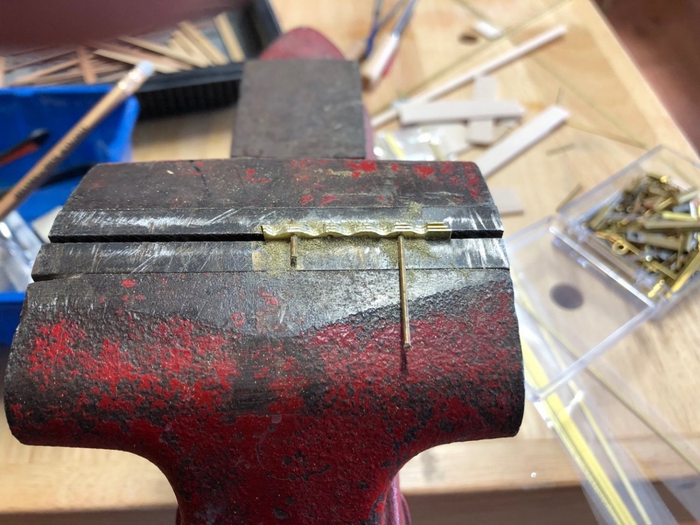
 I had cut all the doors out of boxwood a while ago but now I have been experimenting with how to make the hinges. I came up with this arrangement which is a strip of brass tapered toward the end and bent around the door, cut flush with the back of the door, which I have glued to the doors before I installed them. After the doors are glued to the sides I will add a piece of brass tube with another piece of brass rod sticking out the bottom next to the brass strip. You can see them in the little cup next to the doors. The smaller doors will only have the brass tube for a hinge. I also glued a brass strip to the doors for the closures. These will have a catch glued to them and the sides which you can also see in the little cup. The small kit stove was painted black and then had the hinges glued to the doors, but with these the hinges were glued on after the doors were installed, as per the instructions. I need to paint them black now.
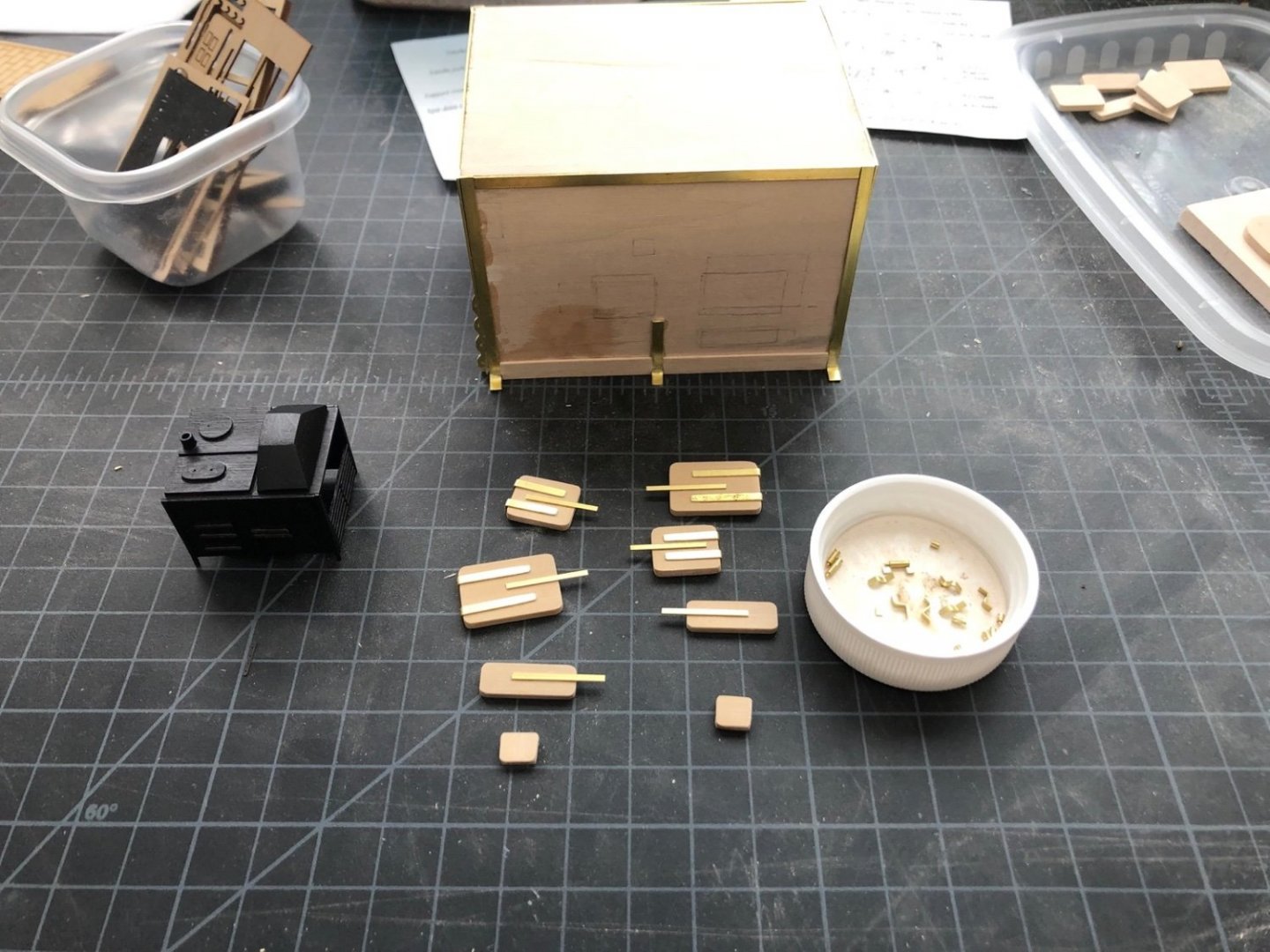
-
Nicely done. I also will use these additional details when I get to the deck fittings. Thanks to you and Derek.
-
Count me in too Gary. We are not that far from the Rangley Lakes region of Maine here in New Hampshire but I have never been over that way. I am going to have to take a drive over and check the area out.
-
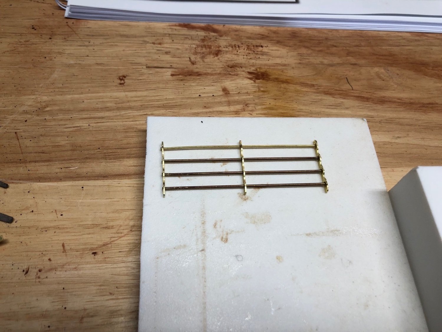
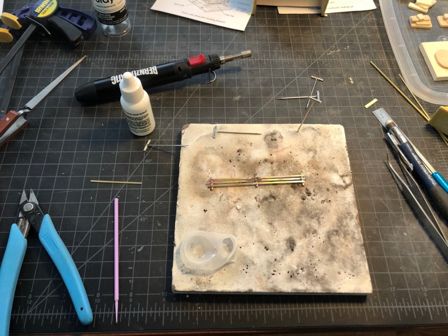
I made the vertical grating today using brass strips for the supports. I drilled a series of holes in three strips using the sensitive drill attachment on the mill, then sandwiched the three strips using brass rod to hole them in the vise to shape them. I used a round and some flat files to shape them all at the same time. I added the brass rod in the holes and used thin CA to hold it all together instead of soldering them. And here are both grates temporarily in place on the frame. I also have started experimenting with painting using parts from the Syren kit stove. This is a black acrylic paint which so far looks good. I think I'll tackle the doors, hinges, and door closures next.

-
I painted the window trim and the pieces that fit on the bulwark tops black. I noticed that the window trim doesn't extend all the way back to the transom, which I think it should. I am not sure how I will deal with that but maybe I'll just paint the area between the trim and the transom black. I also have the counter masked off to paint it blue.
- 118 replies
-
- 3
-

-
- Duchess Of Kingston
- Finished
- (and 1 more)
-
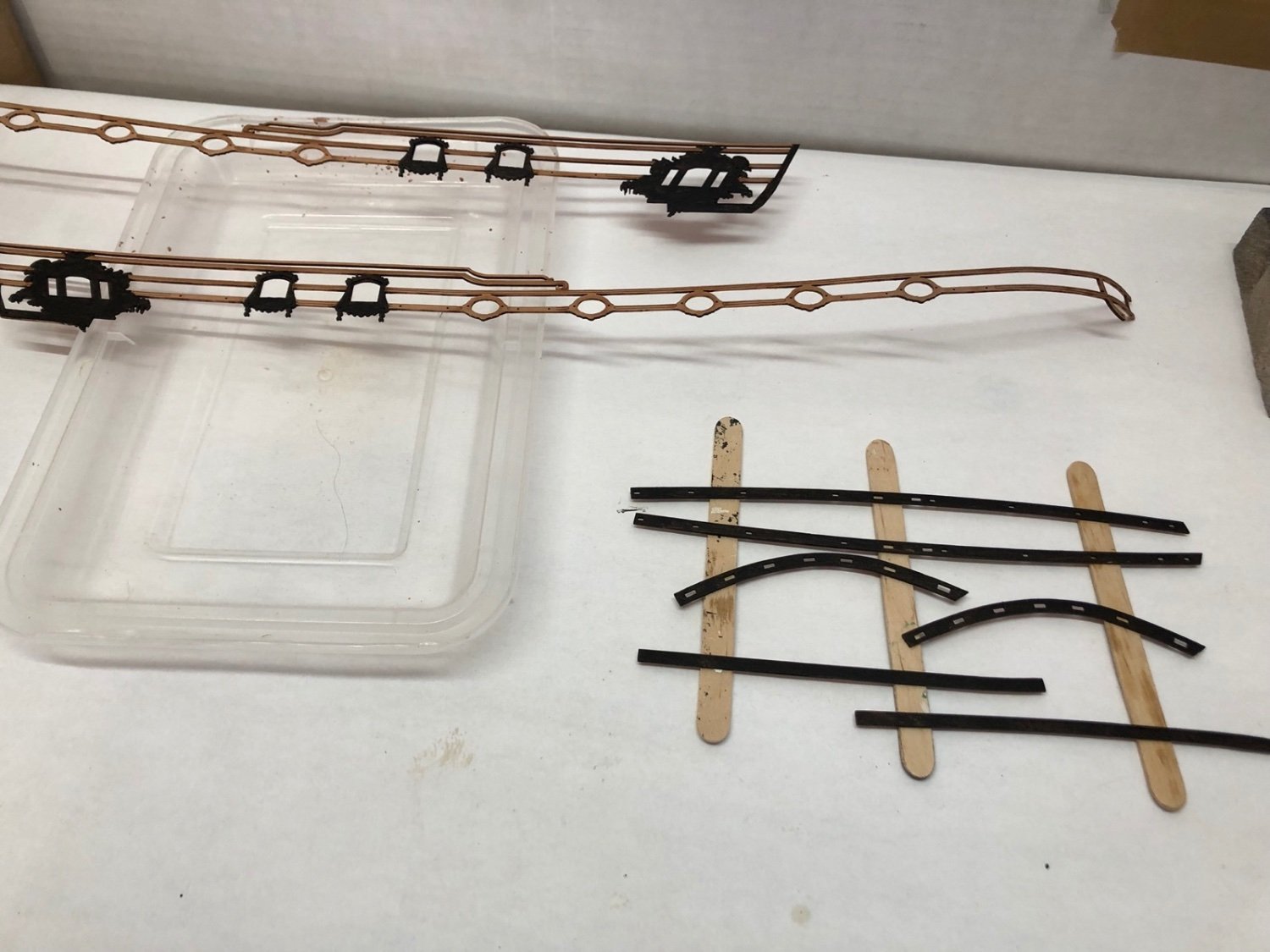
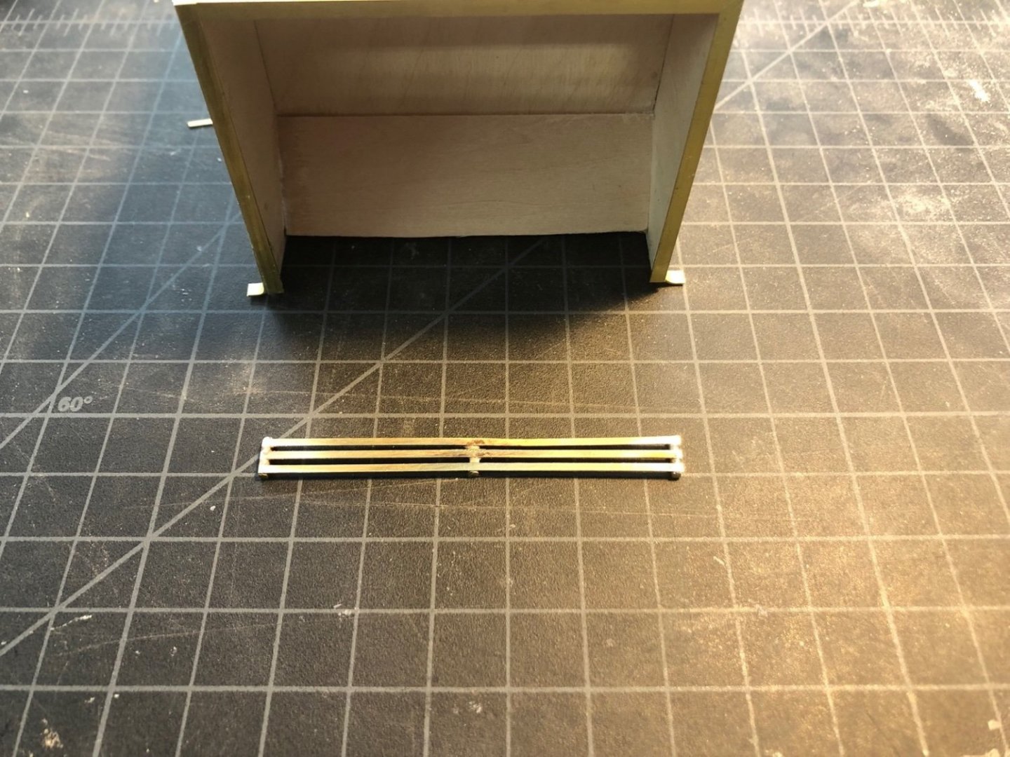
Thank you for the likes. I added the rest of the brass trim along the edges and also added the two middle feet. I then made the horizontal grating that fits in the fore opening. I used three pieces of square brass rod and three brass strips which I soldered together. I left all the ends long then trimmed them off after the solder cooled. I used the disk sander to finish the ends. Here is how it came out after some clean up with a file. I will be making the vertical grating next as well as adding the square bolt heads to the trim. I have some thick brass strip that I will cut into squares for the bolt heads. I am also working out how I want to make the hinges and door latches.
-
Thank you all for the likes. The top trim looks like it molded nicely to the hull, so I did the same with the larger trim pieces that reach back to the transom. When these dry I'll paint the window trim black.
- 118 replies
-
- 1
-
-
- Duchess Of Kingston
- Finished
- (and 1 more)
-
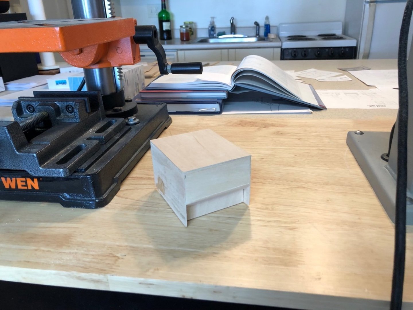
I bent four pieces of brass strip for the legs and glued them to the frame along the edges. I then glued four more strips next to them on the adjacent sides. In this photo you can also see the Syren stove in the background that I am building in parallel. I am further along on that one. The stack is just resting on the stove top for now. I need to add the chimney under it.

-
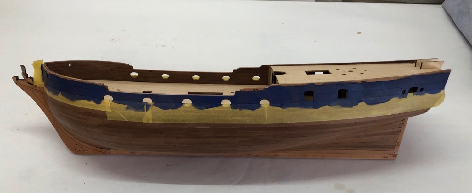
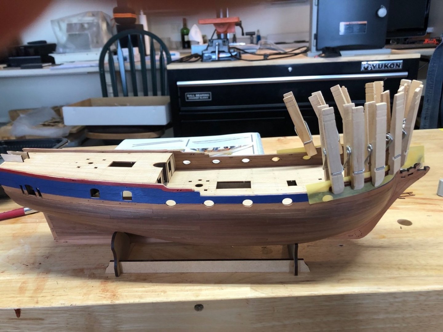
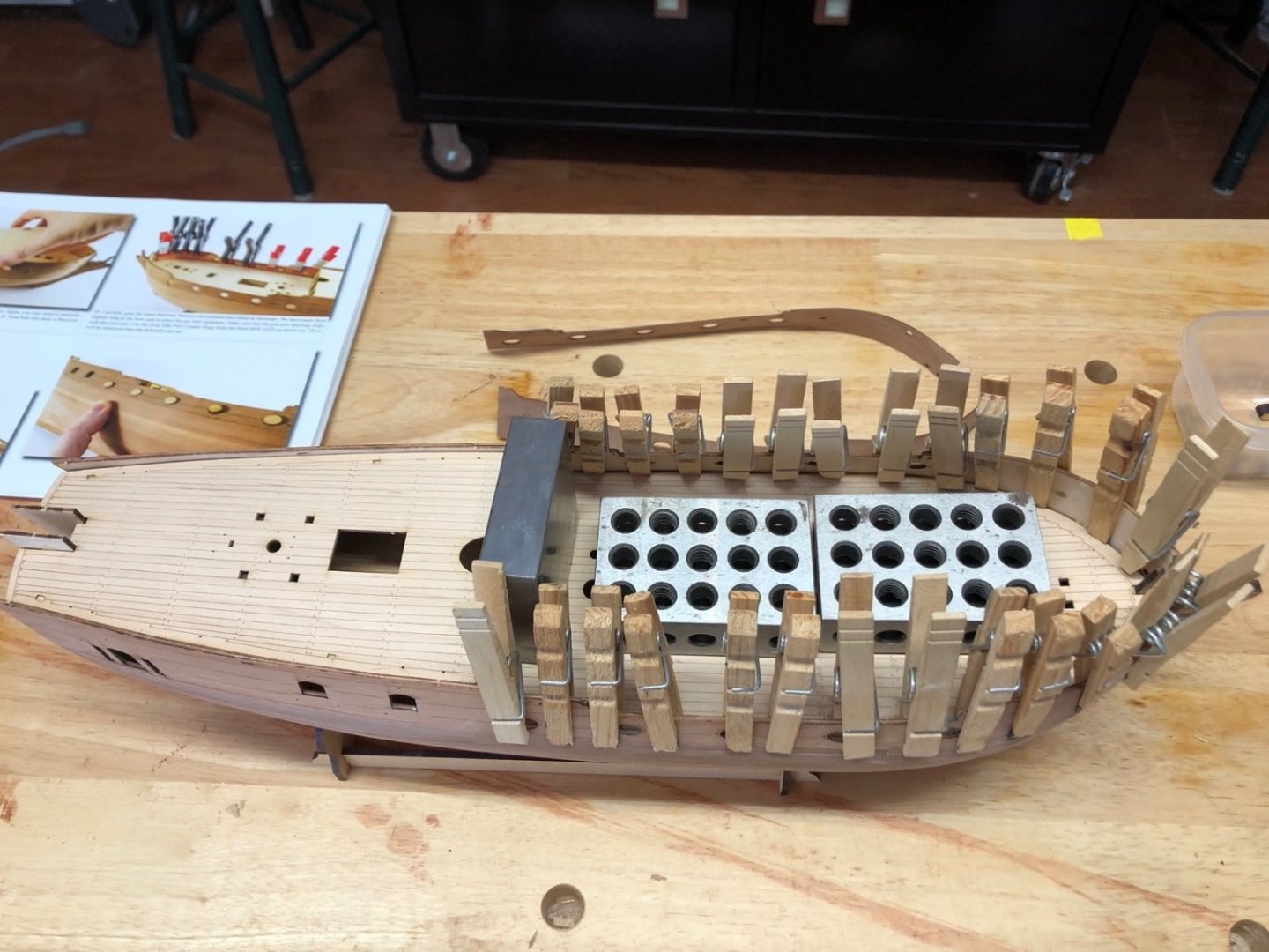
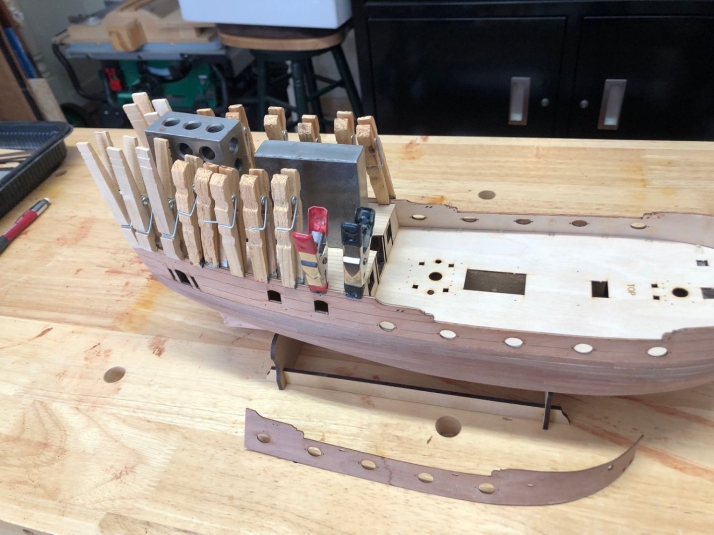
Thank you Elijah. It has been fun so far. I especially like the amount of detail provided and the real thought that has gone into the design of it. @chris watton has done a fantastic job on the kit. I masked off the top of the blue paint and added the red paint at the top of the bulwarks. I then soaked the top bulwark trim in hot water for 30 minutes and slowly bent it and clamped it to the hull. I will let this dry overnight and then do the same thing with the larger trim that goes below it.
- 118 replies
-
- 6
-
-
- Duchess Of Kingston
- Finished
- (and 1 more)
-
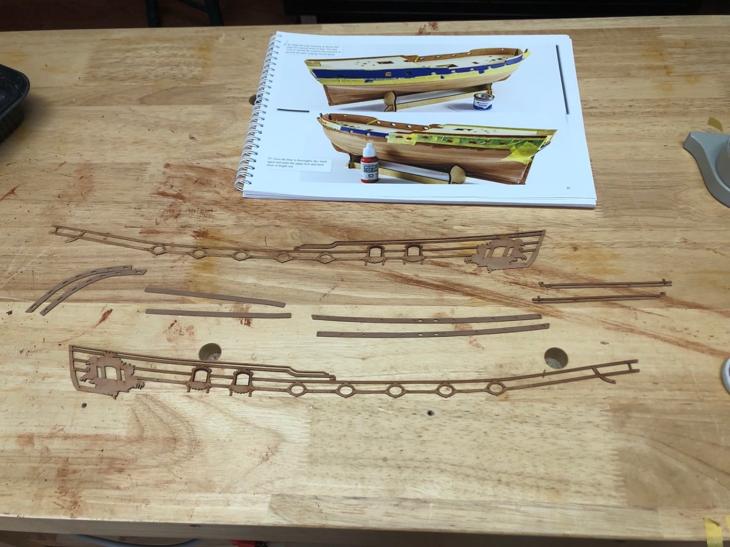
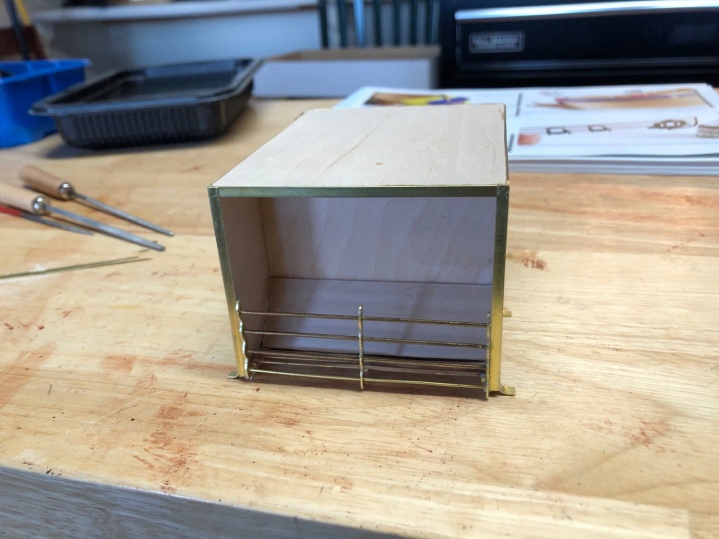
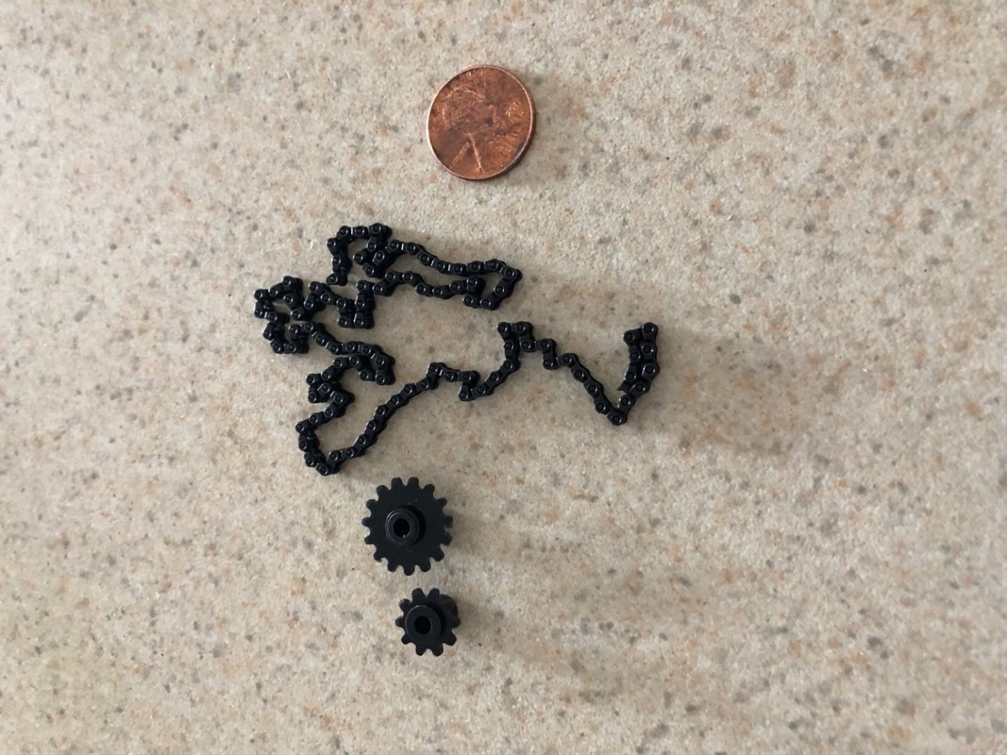
I have just about finished the frame for the stove. Here are the aft and fore views. I have also made all the blanks for the doors from boxwood. The next step will be adding the details around the side edges and making the grates for the fore side. I was able too find some miniature drive chain from MicroMark which will work nicely for the spit drive. I bought gears with it but I am not sure they would look accurate as all the plans I have show pulleys used. I may make some pulleys to use with the chain instead of the gears.

-
I removed the masking tape today after a second coat of blue paint yesterday and I was relieved to find a nice paint line all the way across each side of the hull. I am going to wait another day for the blue paint to fully dry before masking it off for the red sections along the bulwarks. While waiting for the paint to dry, I cleaned the char off the outer trim pieces and the tops of the bulwarks. This was tedious work, but I managed to not break anything while doing it, which again surprised me. I am going to try soaking and bending these as they are now once the red paint is finished. There is still char around the window frames because these areas will be painted black before the trim is added to the hull.

- 118 replies
-
- 8
-
-
- Duchess Of Kingston
- Finished
- (and 1 more)
-
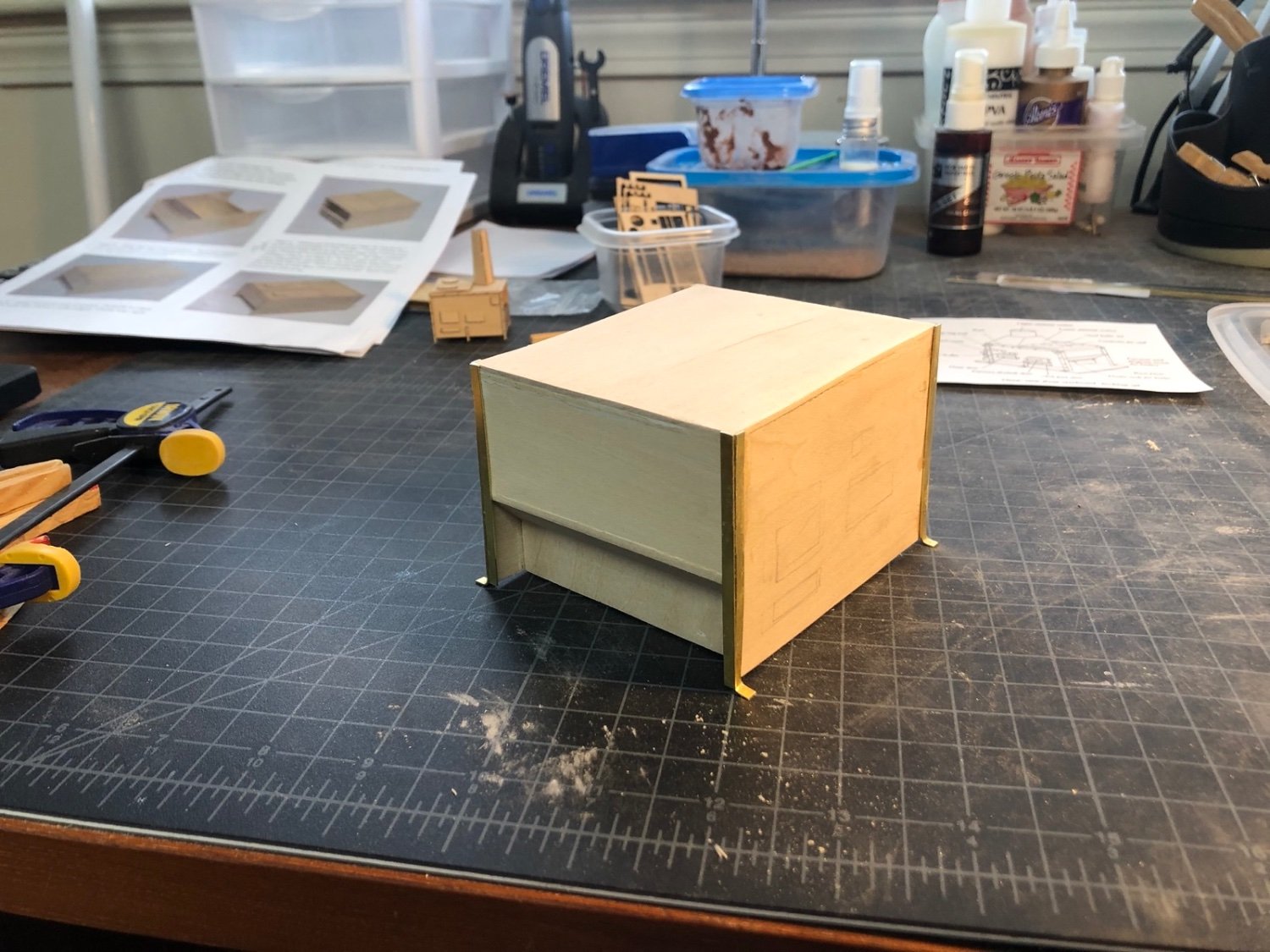
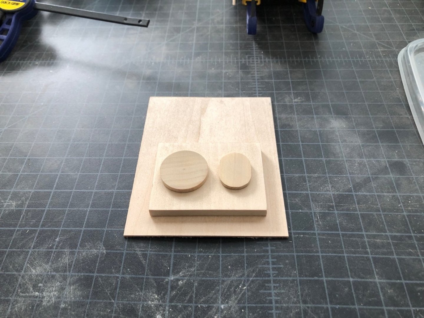
Love it Alan - that is my favorite movie. I have the sides glued to the base and the top will be next. In the mean time I made the top of the boiler from a piece of 1/4" basswood and the boiler covers from some boxwood. The round cover was turned on the lathe using a chunk of boxwood I had left over from the capstan project and the oval cover was roughly cut and sanded to shape on the disk sander.
-
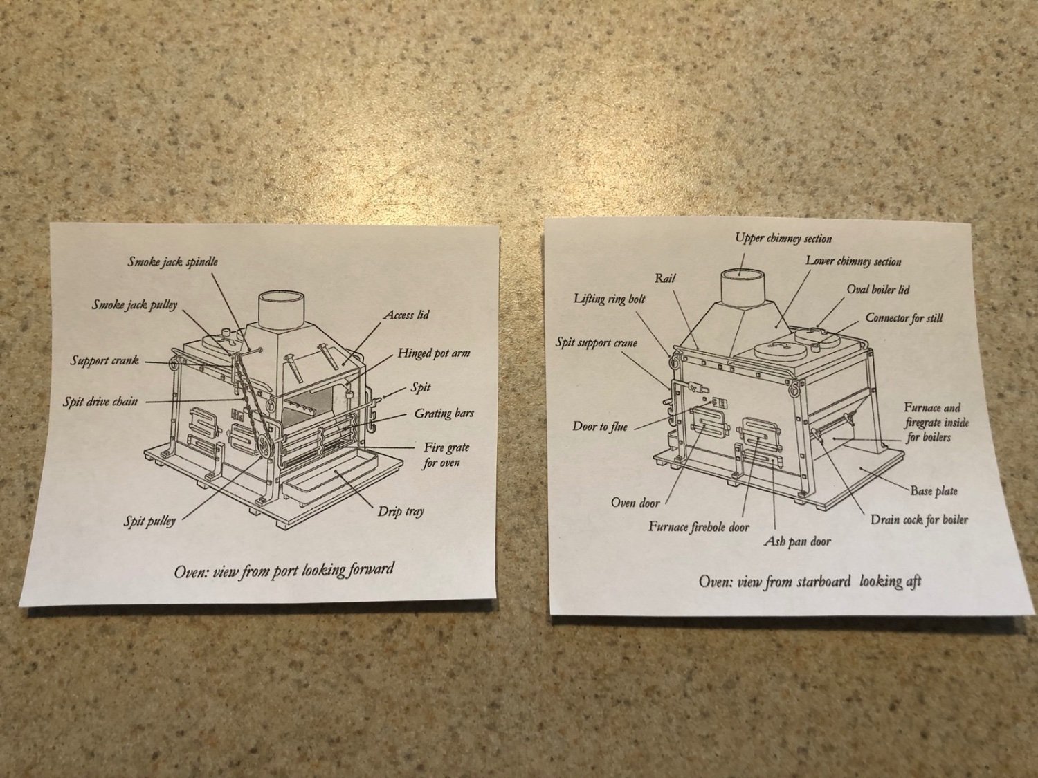
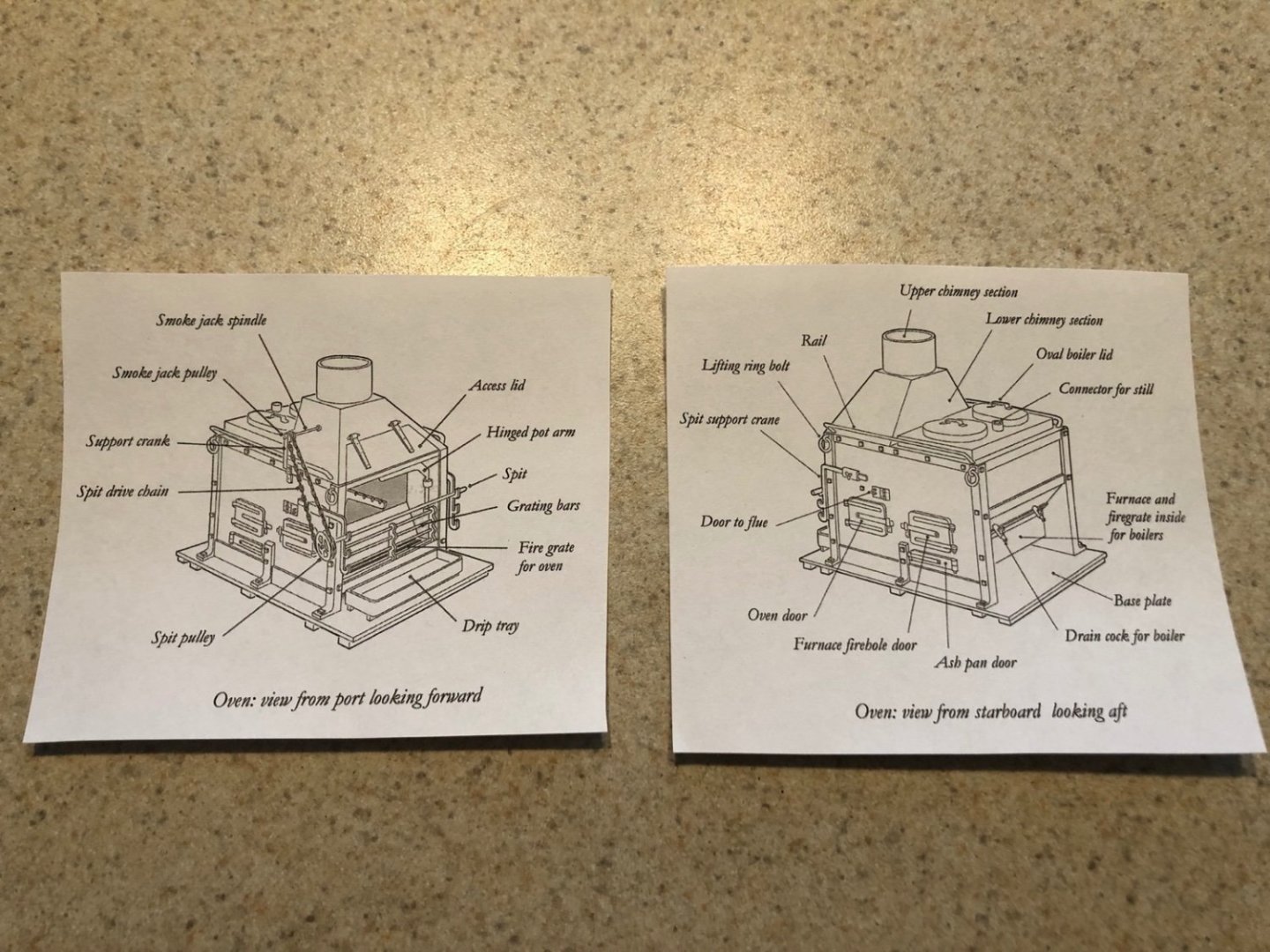
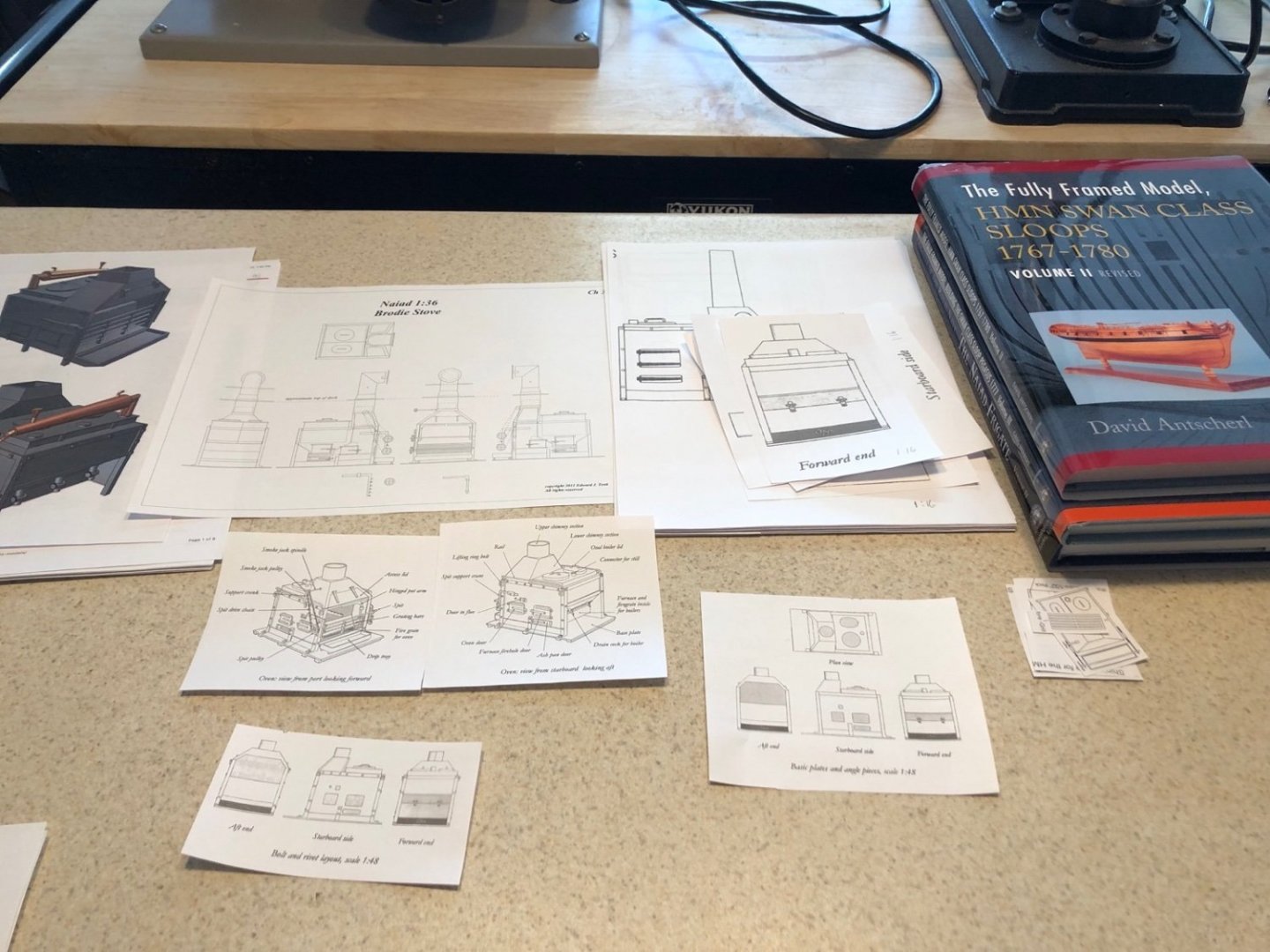
So it has Alan. As I glue up the base for the 1:16 scale stove I am starting to decide what details I will add to it. Because of the size, I can add quite a few more details than is shown on the 1:48 scale stove. I am going to try and include the bottom and side grates, the pulleys and chain for the spit, handles, ring bolts, square bolt heads, drain cocks, and hinges on the lower chimney. I can either use a brick base or an iron plate base, with the iron one probably more accurate for the time period of the Swan class ships. This base goes between the legs of the bitts, so the display may now include the bitts too. Here is the detail I am after, which is from the TFFM book. Here is a look at the various diagrams and images I have of these stoves so I may try to add some other details like the condenser shown in the image. There is also the beautiful drawing from the CD that came with the Niade book. This is becoming more interesting as I get into the research.
-
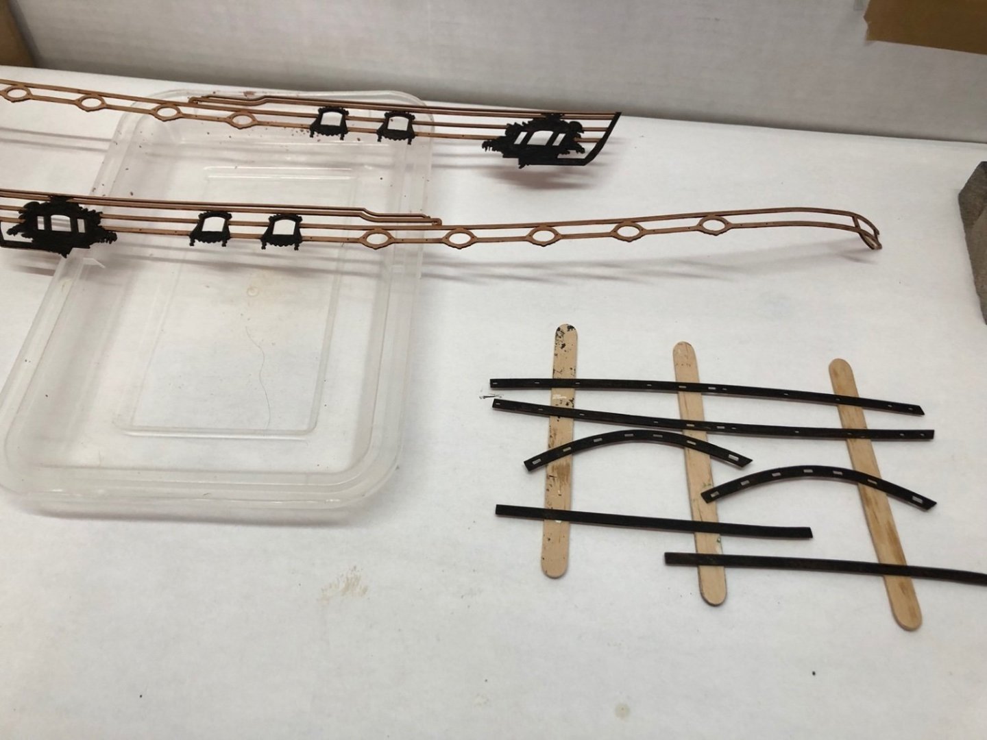
To start the painting of the upper bulwarks, I masked off the lower hull. I brushed on some wipe on poly over the edge of the masking tape to help prevent bleeding. I then gave the upper bulwarks the first coat of Humbolt Matt Blue enamel. So far, so good. I also started cleaning up the wood trim pieces that will be added to the outer hull after it is painted. These are very delicate and require a light touch. As others have done I will separate some of the rails of the larger pieces so I can control where the joints end up.

- 118 replies
-
- 8
-
-
- Duchess Of Kingston
- Finished
- (and 1 more)
-
That's how good Chris' working cradle is - haha. I cleaned up the oval gun ports and the top edges of the inner and outer bulwarks. The next step in the instructions is to paint the outer bulwarks but before I do that I gave the outside and inside hull and deck a coat of wipe on poly. Painting is next.
- 118 replies
-
- 8
-
-
- Duchess Of Kingston
- Finished
- (and 1 more)
-
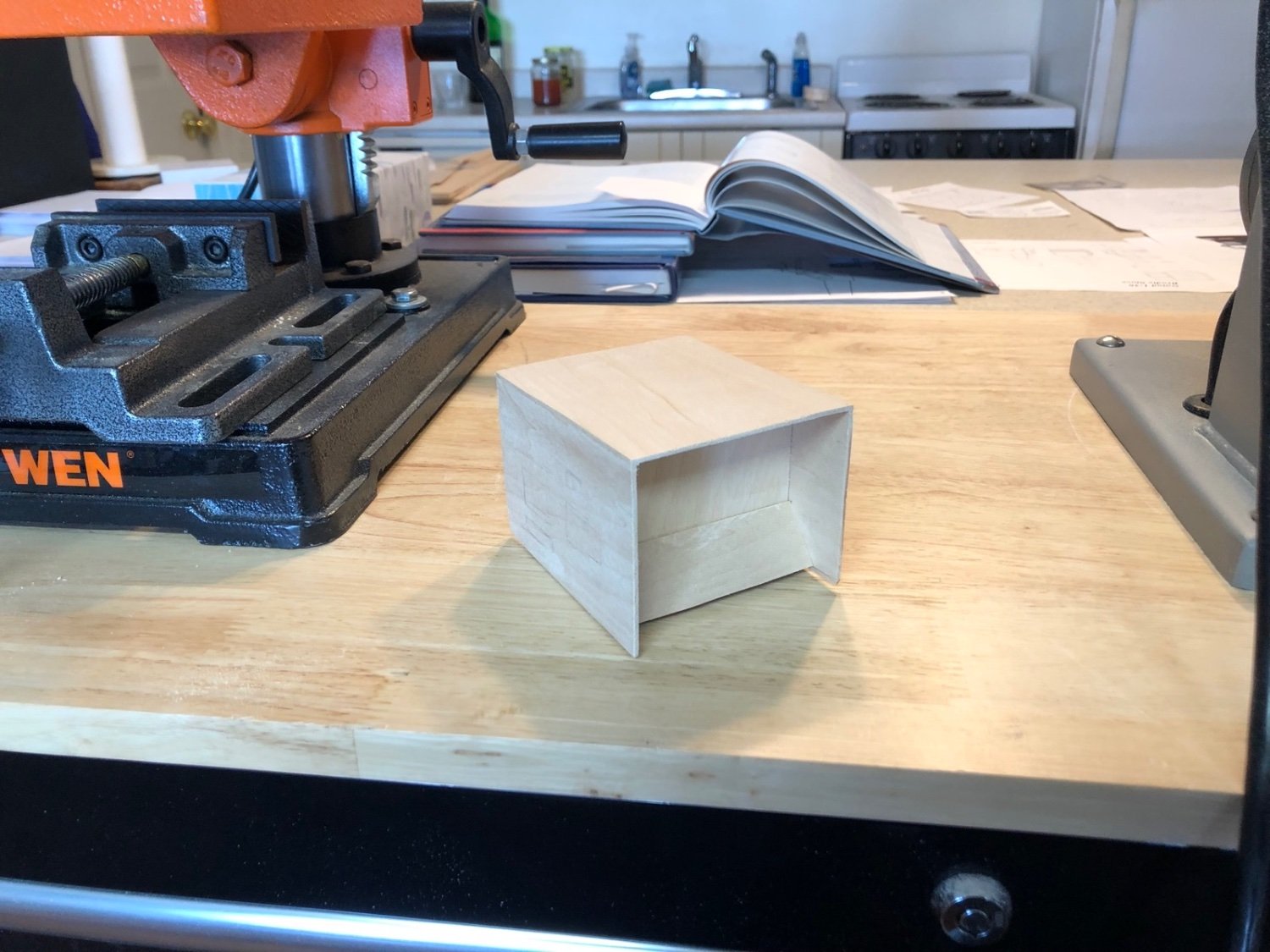
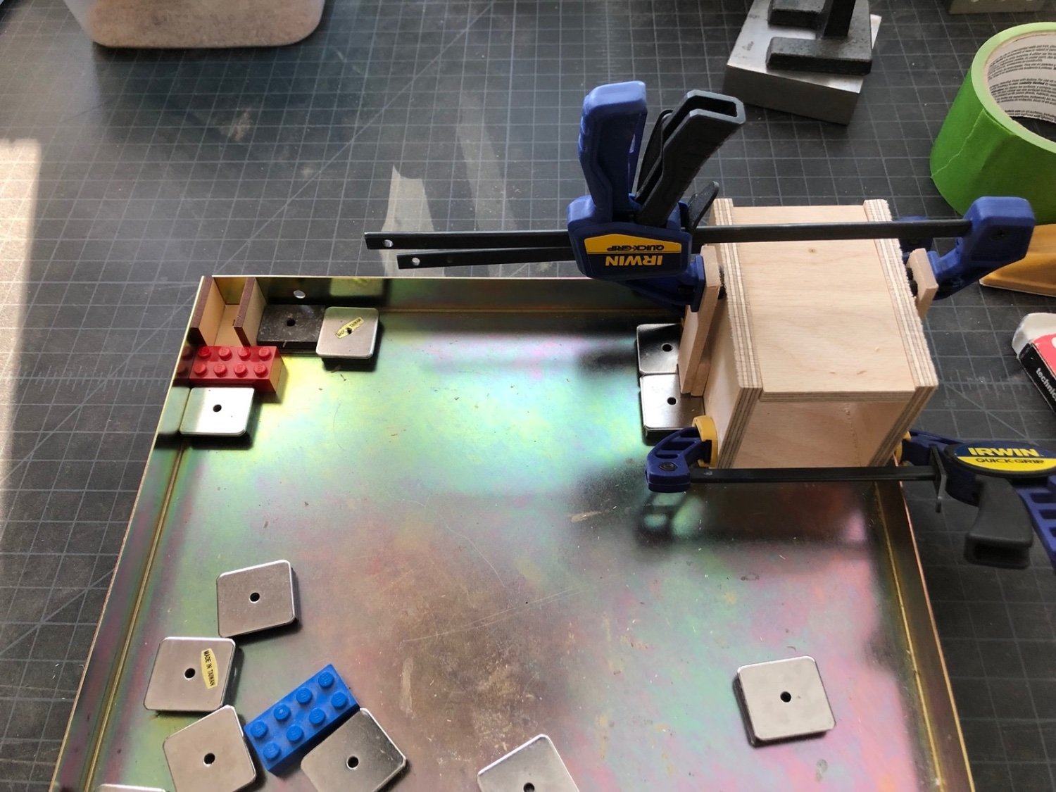
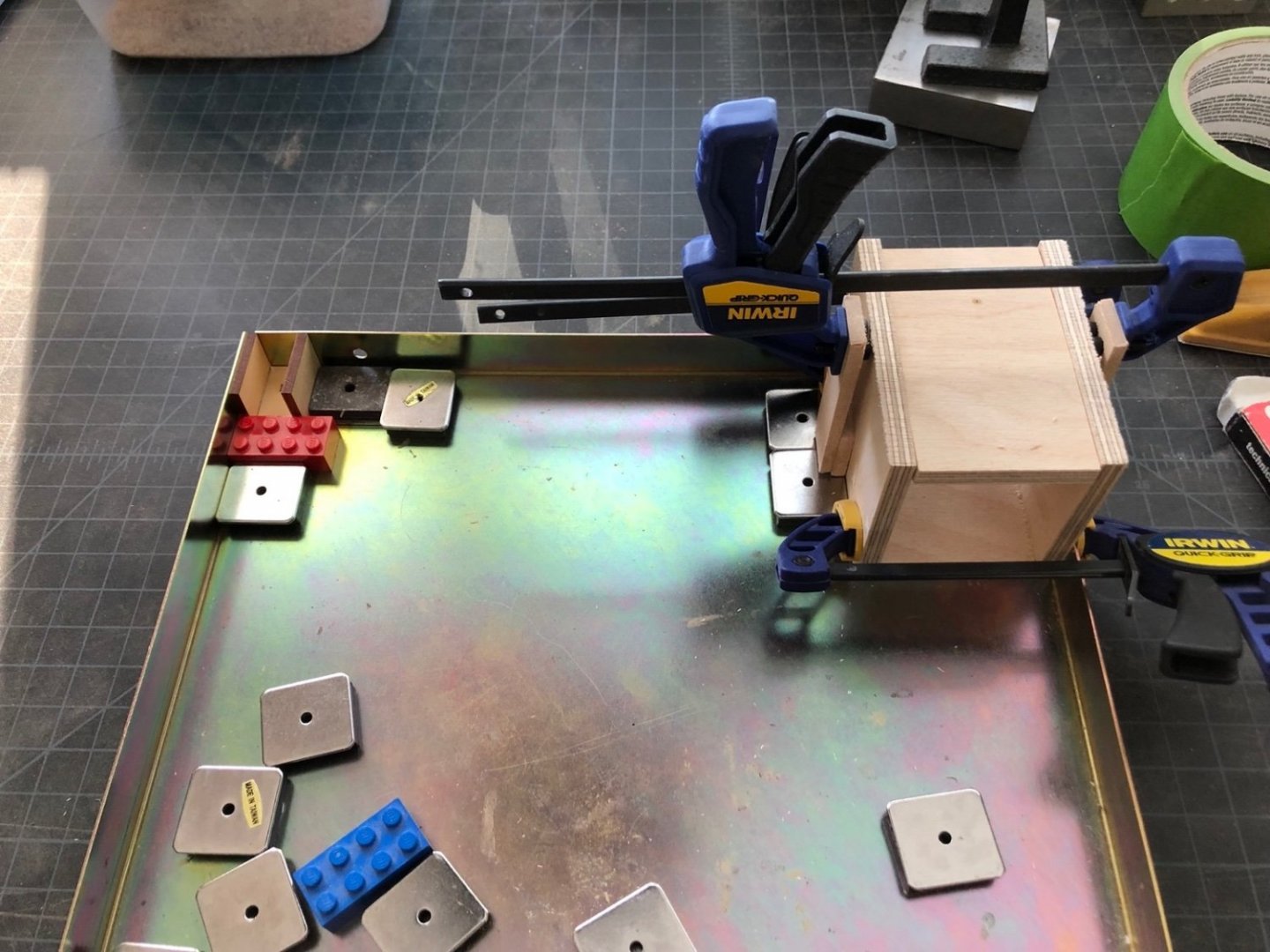
The stove construction has started but only the internal frame. I am using 1/4" birch plywood for the framing pieces. The frame is very similar to the Syren stove frame, just scaled up to 1:16 scale. Here are the frame pieces being glued up along with the kit frame pieces. The piece at the top is just a spacer so the sides will be parallel. I also ordered some weathering powder which I have not used before. Since I will be painting this all black I want to be able to make it look more like metal. I will use the kit to practice with the powder to see what I can do with it.
-
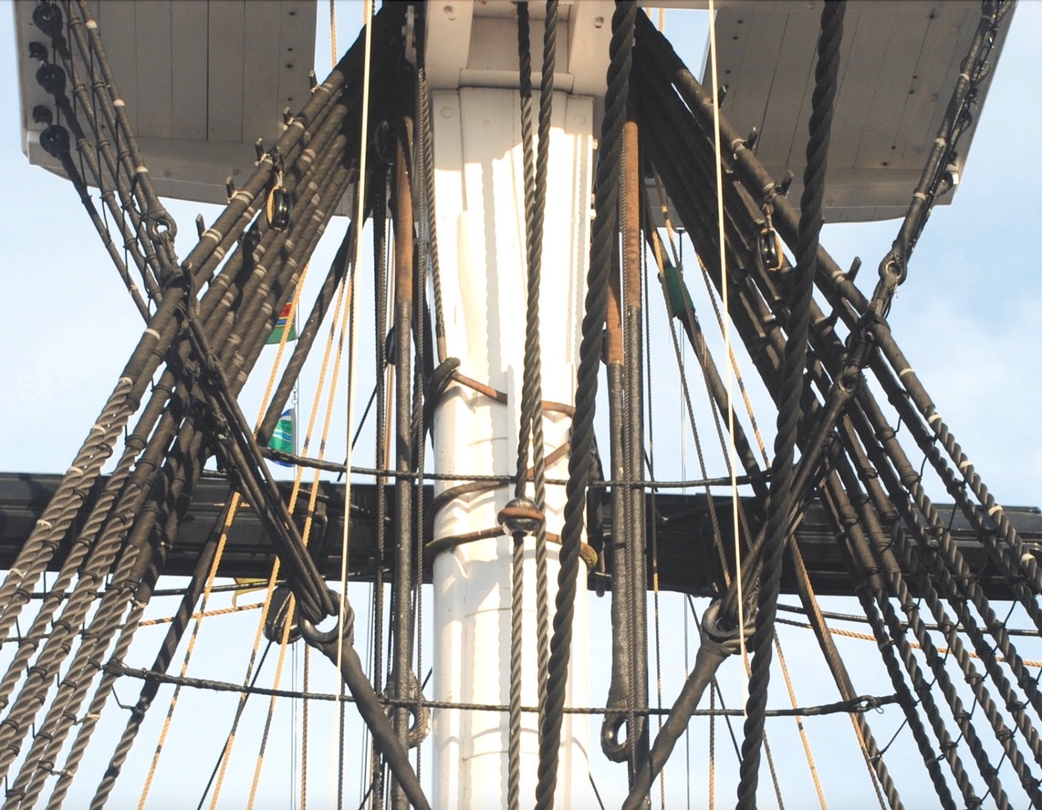
Nicely done on the bentinck shroud rigging so far Tom. That was a very enlightening discussion in my build log on lanyard colors for me. I always used tan line for them, now I only use dark brown, not black. I remember that drawing of the futtock and bentinck shrouds from the instructions and I was equally confused. I then found this image that I took of the area under the fighting top the last time I toured the actual ship, that actually shows the shrouds and how they are rigged. There are a number of thimbles and lanyards that are seized to the futtock staves. I don't think I recreated this exactly on my Connie but it was a reasonable facsimile at that scale. Hope this helps.

- 163 replies
-
- 1
-
-
- Model Shipways
- Constitution
- (and 2 more)
-
Yes this is a scratch build. I am only using the Syren kit as a prototype for the 1:16 stove. None of the kit parts will be in the final build.
-
In continuation of the 1:16 scratch built ships components, my next project will be a ships stove display, to go along with my Capstan and Ships Wheel projects. I am using a variety of sources for this, including the 1:48 stove mini-kit from Syren, and the instructions in the TFFM and Naide frigate books. I will make the bulk of the stove from wood, with brass for some of the outer features. I am hoping to use real gears and chain for the rotisserie but we will see as we get into it. I am just starting the planning for this so it may be a while before I have something to show.
-
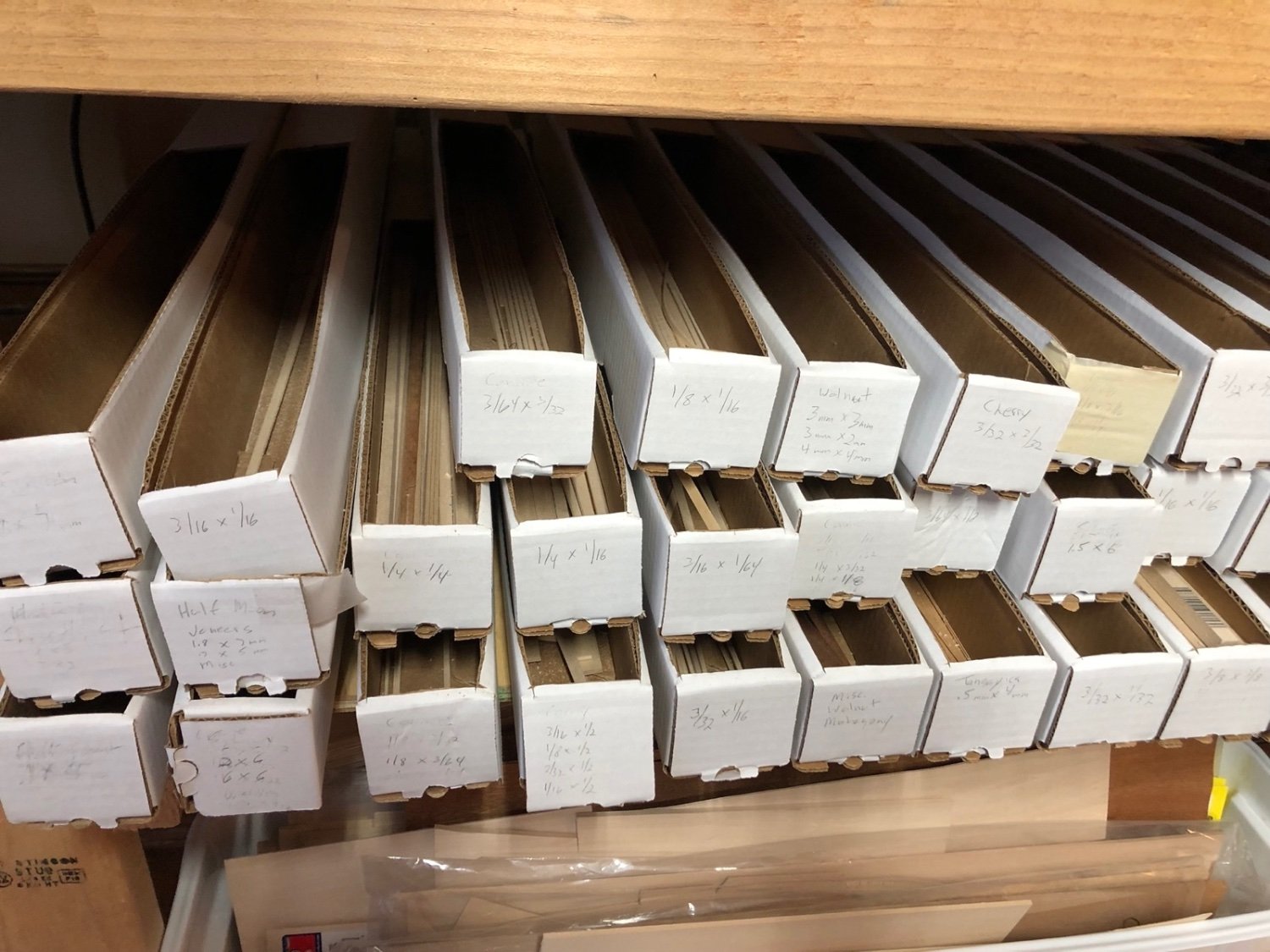
Similar idea but I use square mailing tubes where I cut an opening in the top. Stackable and I can write what's in them on the front.

-
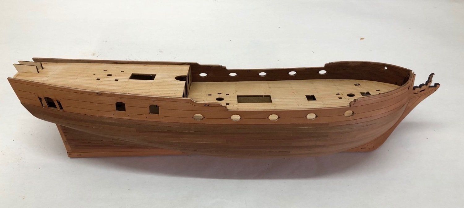
I fitted and glued the two forward inner bulwark pieces in place. Once I had the bow trimmed back to fit, the port side piece fit perfectly but I had to remove some material from the starboard side piece at the deck level to get the spacers to fit into the gun port openings. Even then it was a struggle to get the spacers in place after I put glue on the back of the inner piece. I need to still trim the top down a bit. Today I glued the two aft inner bulwark pieces in place. I didn't do any trimming on these as the fronts matched the forward bulwark pieces and the backs matched the aft pretty well. I did not use the spacers with these as they did not line up with the existing holes, so I do have some holes I need to fill now where the spacers would have gone. And I need to trim quite a bit off the top of the starboard side piece.
- 118 replies
-
- 6
-
-
- Duchess Of Kingston
- Finished
- (and 1 more)
-
When I removed the weights and clamps from the fore deck, most of it was glued down well but there was a slight raised area around the fore mast hole and fore hatch opening. I couldn't get wood glue into the gaps between the deck and plywood sub-deck and I didn't want to risk using thin CA to wick between them, so I tried wicking some isopropyl alcohol between them, hoping it would soften the wood glue that was already there. I put a weight directly on that spot and when I checked it the next day it had worked. So now the fore deck is glued down so I can start fitting the inner bulwark pieces to fit the gun port openings.
- 118 replies
-
- 3
-
-
- Duchess Of Kingston
- Finished
- (and 1 more)
-
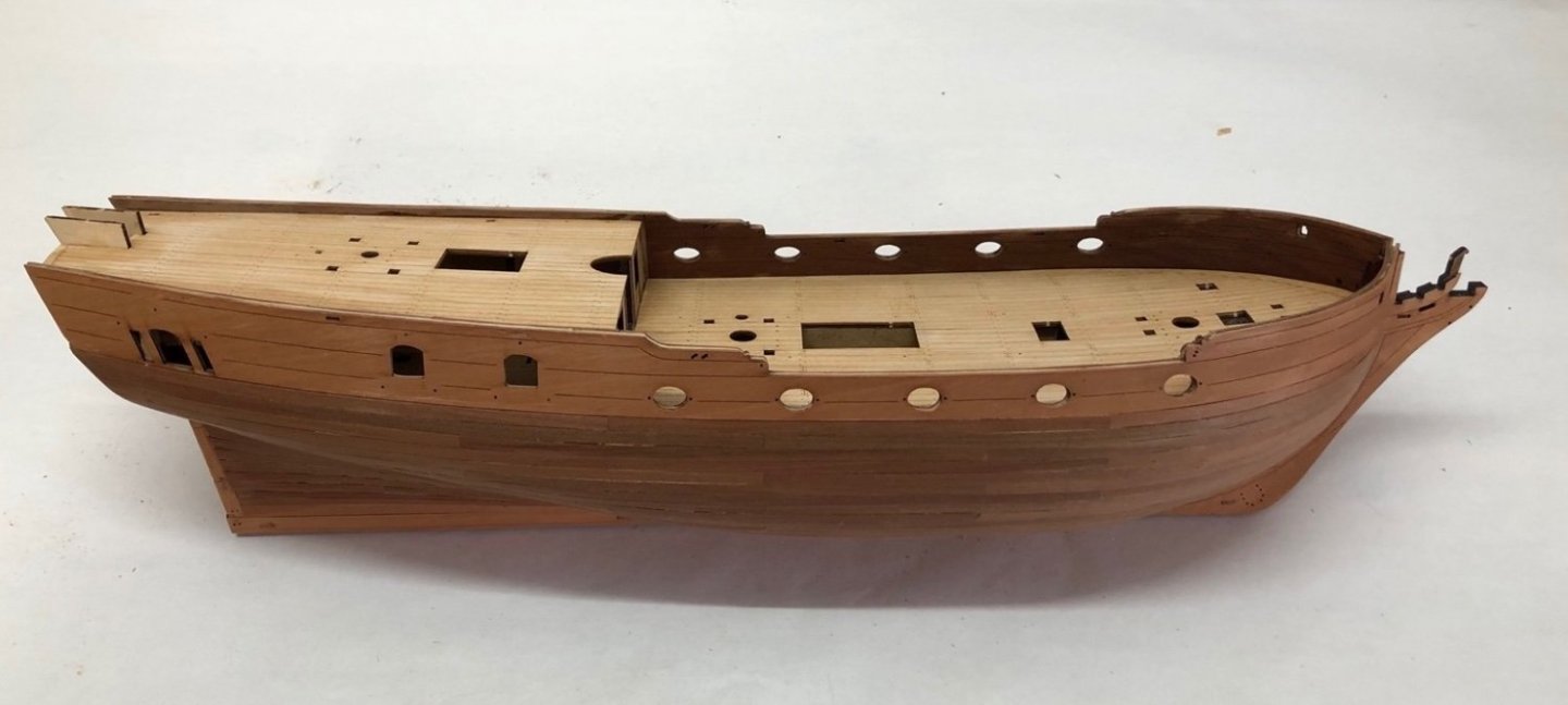
I removed the clamps and weights and the aft deck was held down well, with no bubbles I could detect. So I sanded the fore deck edges to fit and glued it in the same way.
- 118 replies
-
- 9
-
-
- Duchess Of Kingston
- Finished
- (and 1 more)
-
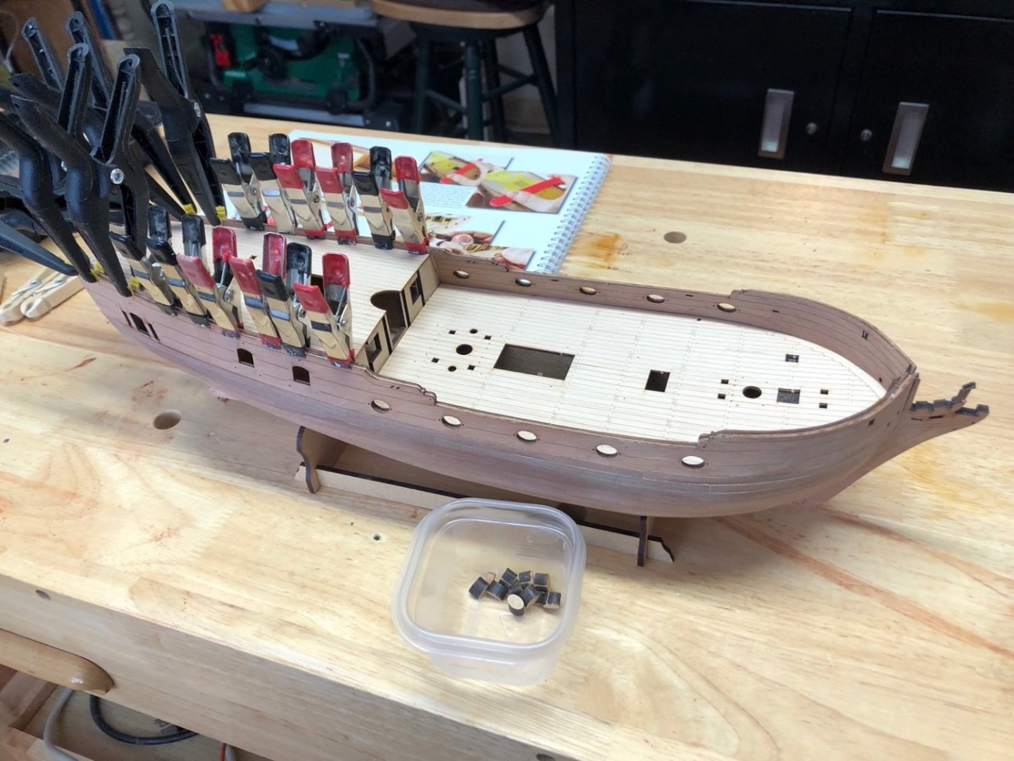
The inner bulwark pieces came out fine but they will need some work to get them to fit when the time comes. The next step is to add the two laser etched birch deck pieces. I am using these although I could have planked the decks but the laser etched plank pattern looks really good. After dry fitting the aft deck piece I brushed wood glue on the plywood under deck, placed the aft deck piece. To hold it down I used clamps around the edges and weights in the middle. When this dries I'll fit the fore deck piece and glue it in.
- 118 replies
-
- 7
-
-
- Duchess Of Kingston
- Finished
- (and 1 more)