usedtosail
-
Posts
2,421 -
Joined
-
Last visited
Content Type
Profiles
Forums
Gallery
Events
Everything posted by usedtosail
-
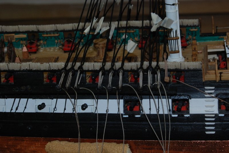
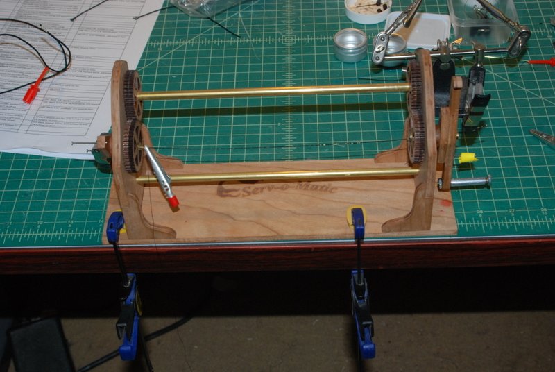
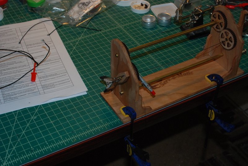
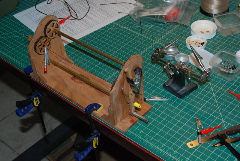
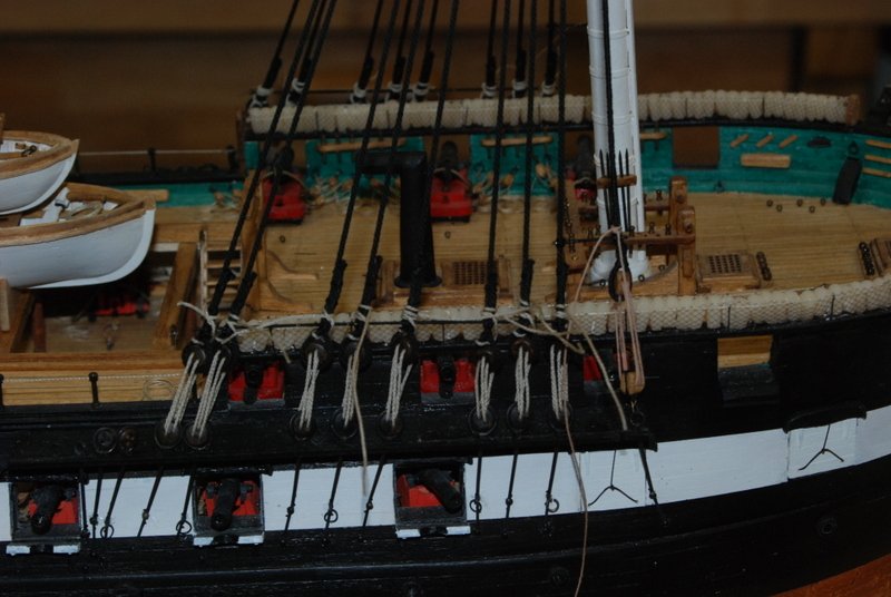
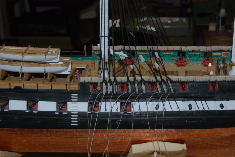
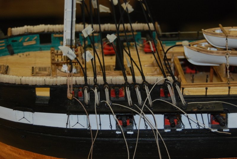
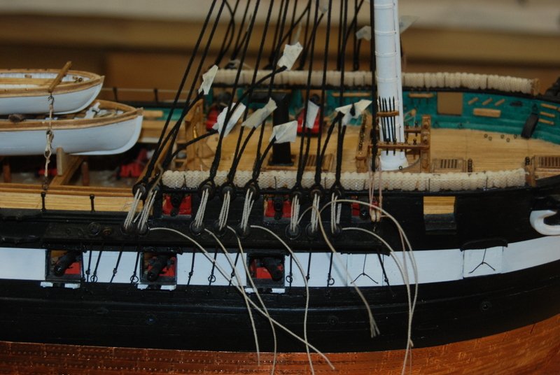
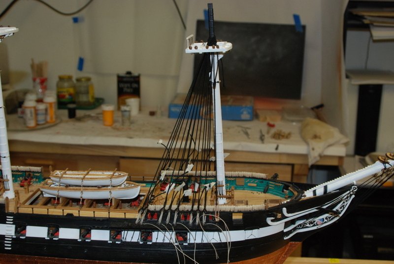
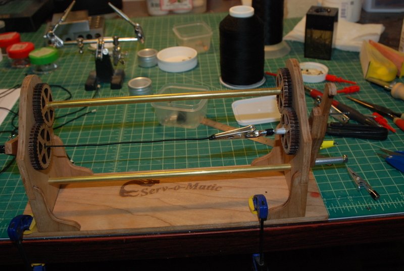
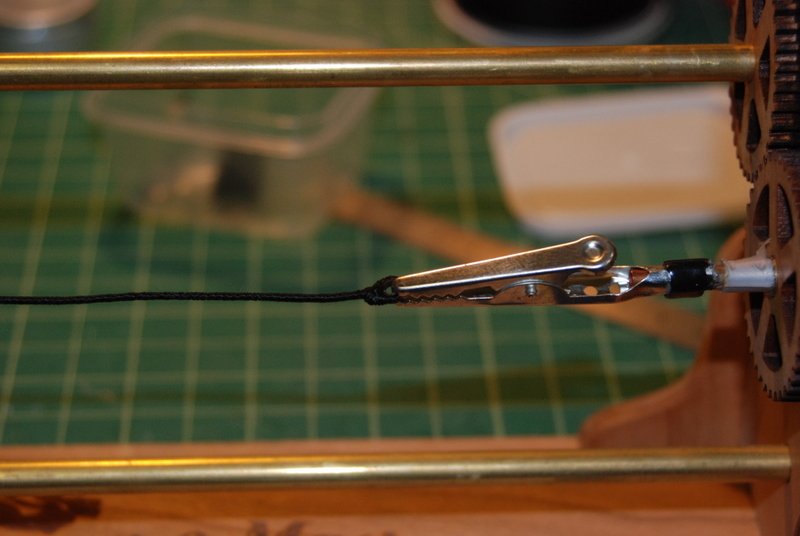
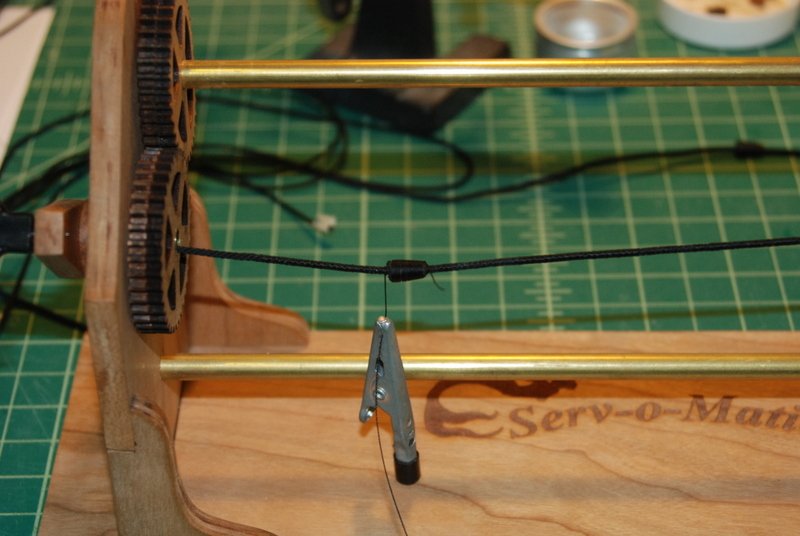
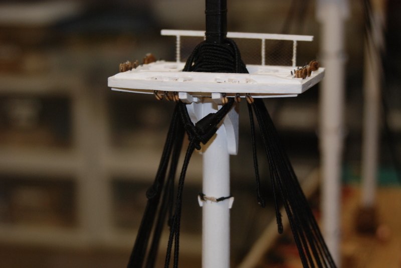
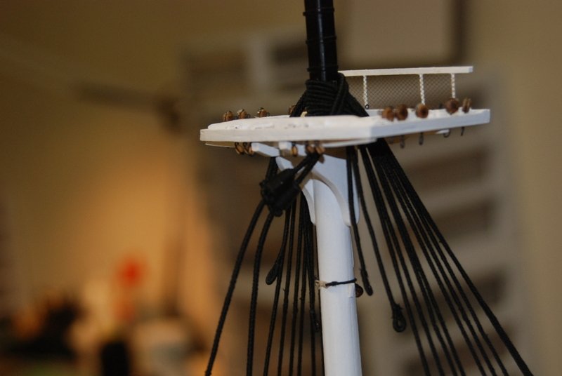
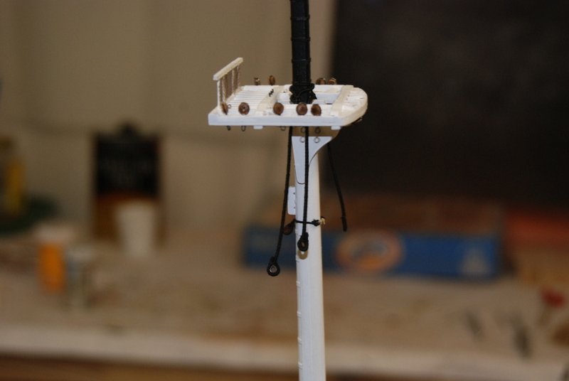
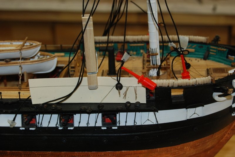
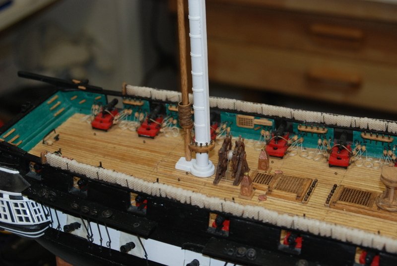
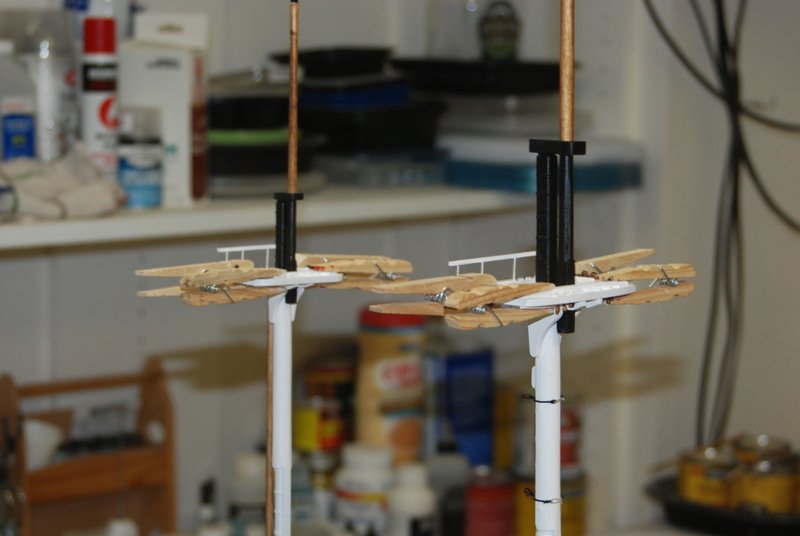
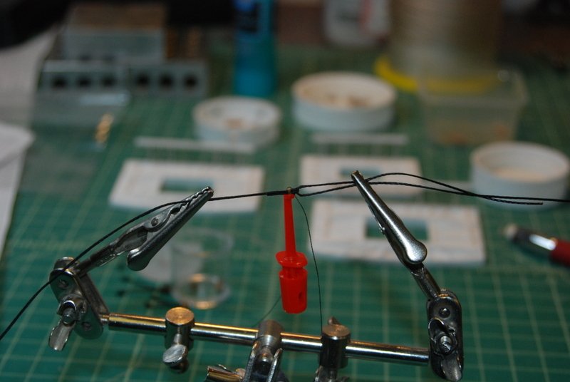
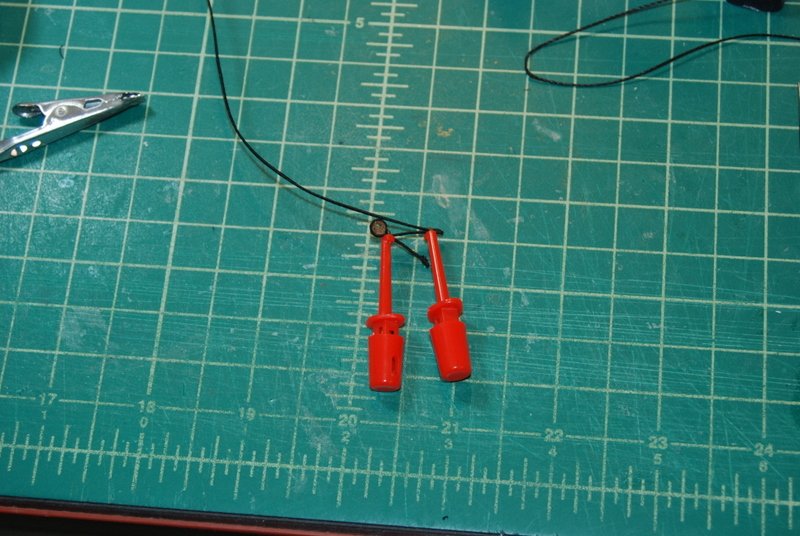
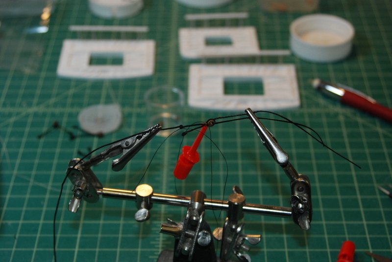
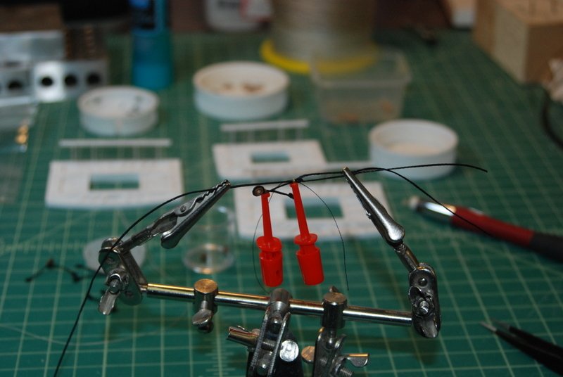
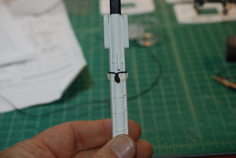
 Thanks for all the likes. I really appreciate them. In spite of some gorgeous weather this weekend, which the admiral and I did enjoy, I managed to get a lot done. It started with making and adding the shear poles to the fore mast shrouds. To make them, I used the thinnest brass rod that came with the kit, which I measured to be about .013" diameter. It took me a while to find a good setup in the serving machine that would hold up for the length of the serving, but I finally came up with this arrangement of clamps which worked well. The trick was to bend the rod at the ends so the clamps could grab them while being clipped around the nails on the serving machine, which prevented them from floundering around when the crank was turned. Of course this only works with full size rods. I did manage to serve a few short pieces by hand, but I wouldn't want to do a long piece that way. I found serving over brass to be a lot harder than serving over line. The serving line wanted to slip so I kept having to stop and bunch it back up with some tweezers. There were still a few shiny spots when I finished but I will touch up any of those that show with some black paint, as well as the trimmed ends of the rods. I tied these shear poles to the shrouds by starting with a loop with a slip knot which I tightened to hold the shroud to the shear pole, then two more half hitches in the same diagonal as the loop, then three more half hitched in the opposite diagonal, finished off with a tiny drop of glue. When all the shrouds were tied, I found I needed to also add some glue to the ends of the pole at the outside knots to keep the poles from slipping in the last knots. The last thing I wanted to happen was the pole slip out of those knots. You can see I also used xken's technique to place a strip of wood between the lanyards to lessen the twist on the dead eyes. There is also a short pole that goes just above the block in the swifter to the first shroud, which I did the same way. After I trimmed the loose ends of all the ties, I retied the deadeye lanyards to the shrouds above the poles. I used a combination of half hitches and loops to tie them. Further along in the build I will finish off the lanyards by seizing the ends to the shrouds. I finished adding all the lanyards to the main mast shrouds, and made one of the main stays. After I was satisfied with it I made the other main stay, but it was late last night so I don't have a picture yet. Here is the first one in place. Next up is to add the shear poles to the main mast, then start on the mizzen shrouds.
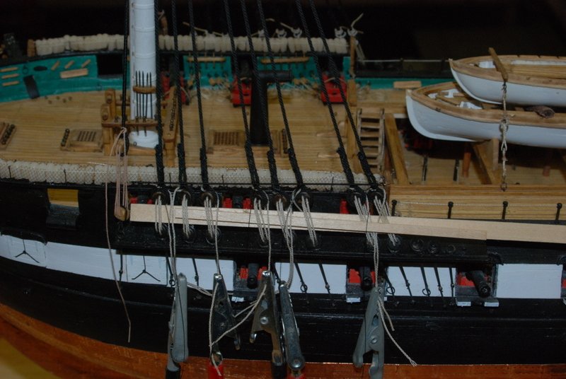
- 1,354 replies
-
- 7
-

-
- constitution
- model shipways
- (and 1 more)
-
That's a good tip Ken. What I did for the fore mast was to loosen up on the deadeye lanyards on the shrouds, added the stays, then tightened the lanyards back up, which put tension on the stays and pulled the mast into the correct rake angle.
-
Nice job on the main stays and the snaking, Ken. I am going to be making mine this weekend, but not snaking them yet. I will keep your method for snaking in mind when I get there.
-
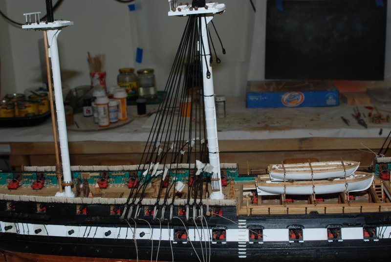
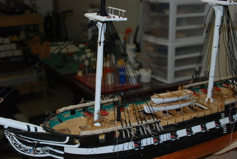
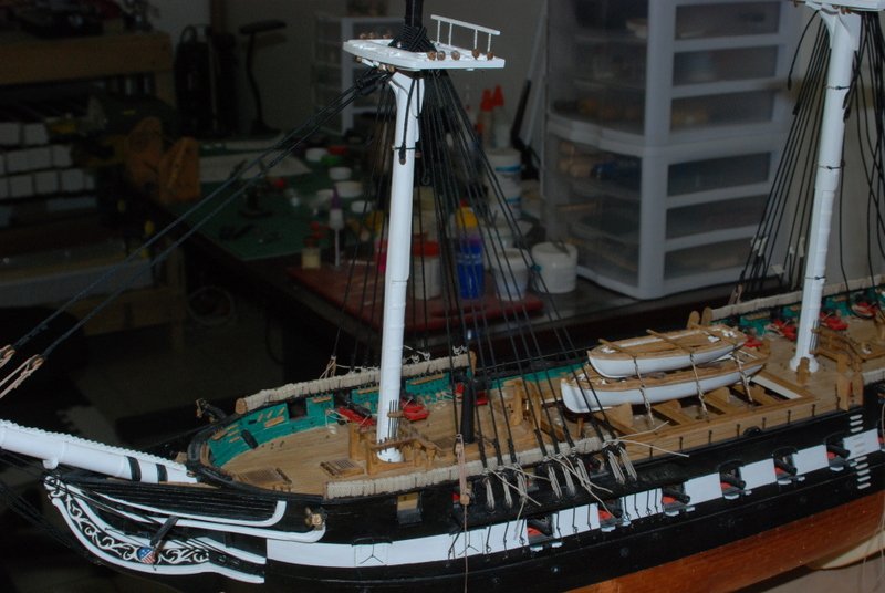
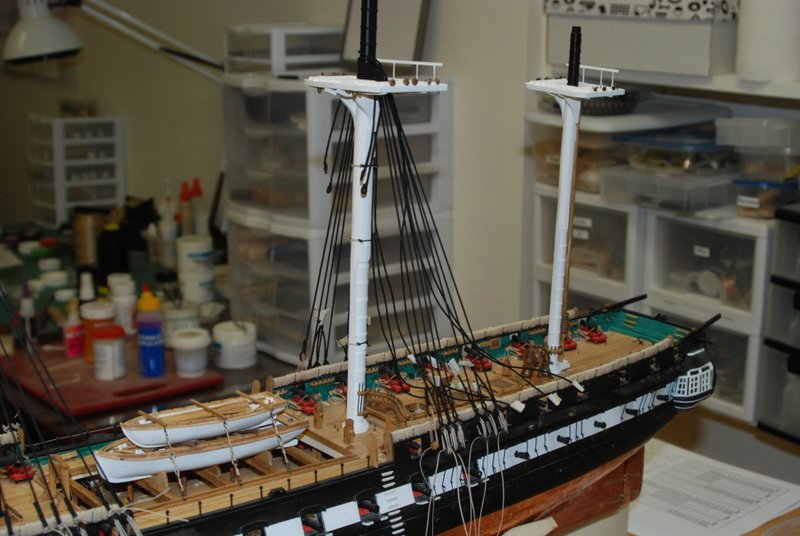
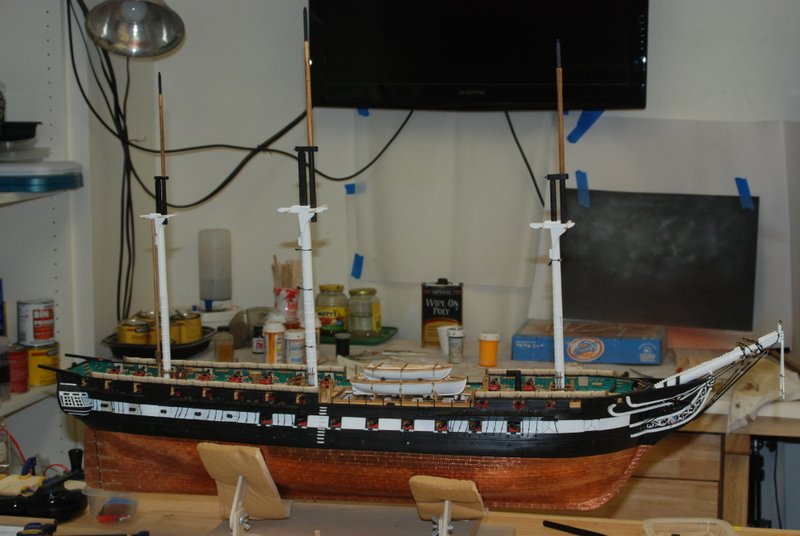
Here's some status for the week. I was away last weekend cleaning out the stuff from my father's basement, so all of this work was done after work during the week. He lived in the house over 50 years, so you can imagine what he accumulated. Found some good stuff to save though, and some good memories. My son and nephews chipped in big time to help me out so we filled up a 20 yard dumpster in about 5 hours. I finished up the fore mast shrouds and stays last week, and here is how they came out. This week I was focused on the main shrouds. I have all of the dead eyes seized and the lanyards in place. I will finish them off after the main stays are added, so I can adjust any tension that needs it. Starboard side: Port side: I am now noticing that the last dead eye is a little higher than the others, so I need to correct it. I also see from Ed Tochi's log that I should probably have put the shear poles in before tying off the fore shroud lanyards. Good thing they are not glued in place yet, so I can loosen them up to put the poles in without too much trouble. My goal this weekend, after those fixes, is to get the main stays made and installed and maybe finish off the main shrouds. We will see...


- 1,354 replies
-
- 10
-
-
- constitution
- model shipways
- (and 1 more)
-
Excellent advise Frankie. I use that technique for all my seizings and it works great. Once I learned to do it properly rigging became a whole lot easier. One tip for you Mike, pull everything tight with the end marked a before you pull b. Otherwise you might get loops that form in the middle.
-
Thanks Robert. Bill, you know I was looking in AOS the other day and saw them and had to stop and think, but I came to the same conclusion as you. It could have had them in 1812 or not have. I am sticking with not including them, but I hope to build a model in the future that has them because they do look cool.
- 1,354 replies
-
- 1
-
-
- constitution
- model shipways
- (and 1 more)
-
Thanks Rob. So far this is the best rigging I have done to date. I am really taking my time. Dan, thanks too, and what a great tip! I had never thought to do that. I can see that one paying off soon. Popeye, thanks. It is tedious but I like it a lot. Lots to go but it is all good. And thanks for all who hit the like button too.
- 1,354 replies
-
- 1
-
-
- constitution
- model shipways
- (and 1 more)
-
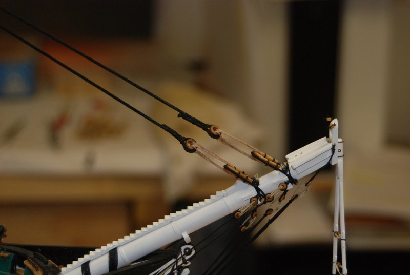
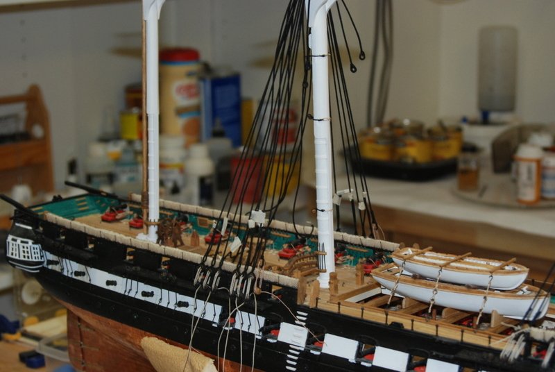
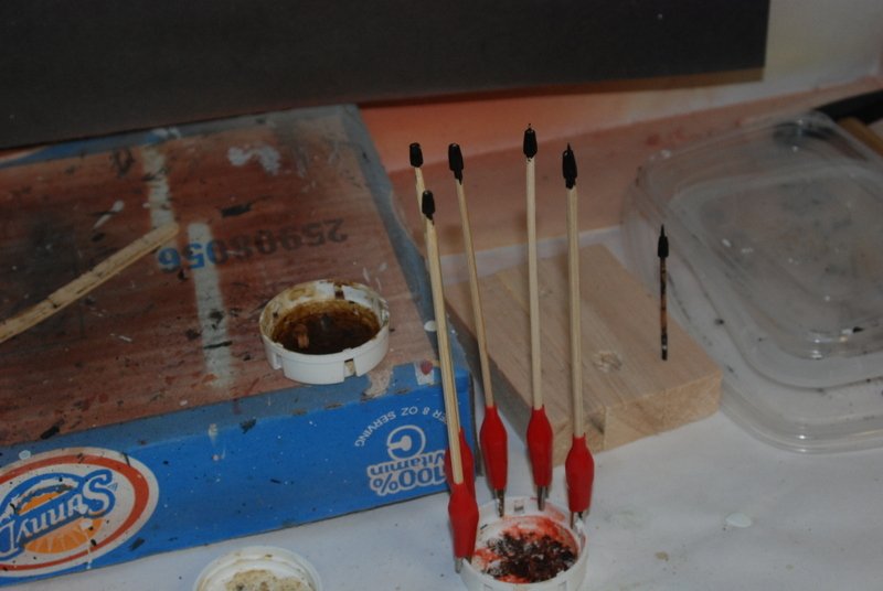
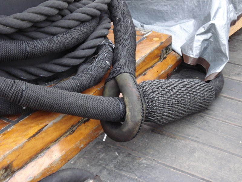
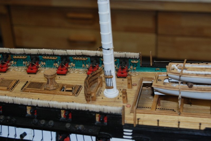
The mast rigging continues. I have been working mostly the fore mast shrouds over the weekend, and they are pretty much done now. I made the line for the lanyards in my rope walk, but the shrouds themselves are .045 line from Syren. The lanyards are not tightened down yet. I still have to add another seizing on the shrouds above the two that are already there. I am pretty happy with the alignment of the deadeyes, although I did have to redo the seizings on a couple. I am working on the fore stays because I need them to offset the pull of the shrouds on the mast, especially those back ones. I experimented with different ways to make the mice I need for the them. I started with Sculpey but couldn't get the hole big enough for the large line to go through without the mouse collapsing or disintegrating. I ended up making them from dowels on the lathe, which came out pretty nicely and was not very hard to do. I made all six mice I need for the lower stays, and painted them black. I also ended up making new closed hearts for the fore stays because the laser cut supplied ones fell apart as I was cleaning the char off them. I like the new ones better because I was able to cut a groove around the outside for the stay line. You can see them in the little jar lid on the box after I stained them. After I tried the mice on the fore stay line, they looked a little wooden to me, so I put them in the serving machine and wrapped them in line. I think they look much better now. For comparison, here is an actual mouse from the Constitution on a stay (not sure which one this is). You can see that the lines go more front to back than around it, but what the heck. You can also see how the serving looks on these large lines. Here are the fore stays around the top of the mast. I did not have the closed hearts seized to these lines when I took these pictures, but they are now. I also started making the pendants and shrouds for the main mast. In making the pendants, I tried something I haven't before, and that is wrapping line around the bottom of the loop around the thimbles in the serving machine, which made them look more like a splice to me. I actually did this to one of the fore mast pendants too, but that was done by hand and not in the machine. I like the look of these now better than i did before. It always seemed to me that the seizing was too far from the thimble. This method covers the gap nicely. You can see another modification I made to the serving machine, which is just an alligator clip with a snug fit into the tube the line goes through. I am finding many uses for this clip, including being able to hold line very close to the end so I can serve almost a complete length. I made the mistake a few times of cutting a length of line to almost the exact length, which didn't leave enough to wrap around the nails on the outside of the machine to serve its length. This solves that problem by letting me hold the end of the line in the clip. Another thing I found was that WD-40 makes the serving machine so much quieter and easy to turn. I didn't want to use it on the nice cherry wood, but it was really squeaking so I bit the bullet and sprayed a little on. What a difference! My wife still says I look like Rumpelstiltskin when I am using the serving machine. OK, last picture, here are the pendants and first shrouds on the main mast. Lots more to do there.
- 1,354 replies
-
- 9
-
-
- constitution
- model shipways
- (and 1 more)
-
That is really nice deck framing, Mike.
-
Whatever you call it, it is a great job. Nicely done.
- 265 replies
-
- 2
-
-
- finished
- artesania latina
- (and 1 more)
-
That's OK Jon. I downloaded all those plans off the web site when they were available and have been using some of them for this build. I didn't remember seeing that one before, but I did find it in the set of plans I have. My guess is that it is from the 1930's.
-
Thanks Dave. Yes, the different versions of the ship are confusing. The serving machine from Syren works great, but the finger crank hurts after a while, which is why I added a hand crank. For rope making I have a different machine. JS, do you know the date of those plans? They show the lower bulwarks on the quarter deck and fore deck, but the waist is closed in. So that is yet another configuration. Thanks Popeye. I usually use a piece of wire to hold the deadeyes, but with so many shrouds on this model the angle between the first and last shroud changes a lot, so I would need a different wire for each deadeye to keep them at the same height, or at least each group of deadeyes, so that is why I made the card.
- 1,354 replies
-
- 1
-
-
- constitution
- model shipways
- (and 1 more)
-
Yes Dave, the bulwarks were extended in the mid? 1800's and have remained that way ever since. The waist area was closed in too with bulwarks, but those were removed in 2007 or so.
-
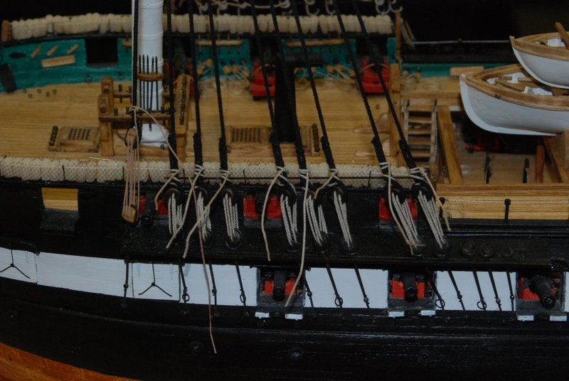
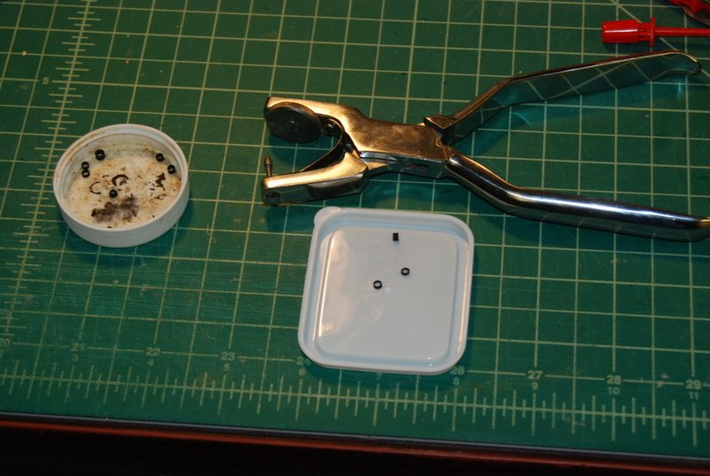
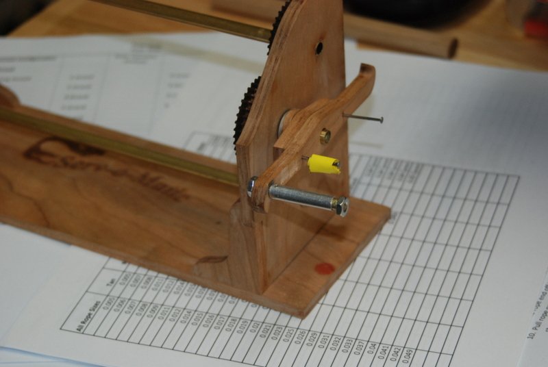
Thanks Popeye and Vossie. Hopefully we'll see some warmth soon. Dave, I am sure your gun rigging will turn out great. My first attempts are now buried in the gun deck so they won't be seen. I have started on the shroud rigging. i am using rope from Syren for these, as I was having trouble making rope this large that looked good for long lengths. The Syren rope is a joy to work with, but I have found that with lot of handling it starts to unwind, so I keep a piece of tape on all the loose ends now. I started with the fore mast pendents, which need a thimble in the loops. I made these from some brass tubing, cutting off small lengths. I used the pliers in the picture to flare the tube and they worked great. Chuck recommended this tool and I am glad that I bought it, as I had tried other ways with little success. After blackening the thimbles, I seized them into some served line to make the pendants. Since I took this picture, I removed them and turned another seizing around the cut part of the line, making it look more like a splice. I made the swifter and all of the shroud pairs for the fore mast and added them to the mast. The swifter is served the whole length and I seized a double block into the ends and stropped triple blocks with hooks to go on the rings on the channels. The gang of lines at the mast head is pretty thick and just fits under the chock for the jeers on the mast. I think as i tighten up the shrouds I can get them to sit down more too. I also started seizing the deadeyes to the shrouds. I'm using a throat seizing just above the deadeye and regular seizings above that. This is the first time I have tried doing the throat seizings and I am happy with the look, but I find tightening them can be a challenge. I make them loose, then pull on the loose end of the shroud while pushing on the seizing with tweezers eventually gets them tight. At that point I clamp the loose end to the shroud and add the middle seizing to hold it in place. I made a crude jig from some manila folder and straight pins, to hold the deadeyes at the right height while I seize the shroud to them, as you can see in this picture. I did have to reattach a couple of pin rails, as the force of the clothes pin on them was too much. They were still attached to the bulwarks by the locating pins i had in them, but they could move enough that I didn't trust it, so I removed them, drilled out the locator holes and glued them back in. It was a little tricky but not as bad as it would be after the shrouds are finished. I now hold the jig to the channel with two pins through bottom deadeyes into the card. Finally, here is the 2.0 version of the crank for the Syren serving machine. My first version didn't hold up to the use I have been giving it lately and was coming loose, so I removed it and made this one. I used a piece of threaded rod in a hole in the wood crank that I tapped for it. The cherry held the threads very well, but I decided to add nuts to hold it too. There are two pieces of tubing on the rod. The inner one allows me to tighten the nut tight to it, and the outer one is a little shorter so it can rotate easily. I super glued the rod into the hole and the nuts to the rod so they wouldn't loosen. Lots more rigging to come...
- 1,354 replies
-
- 4
-
-
- constitution
- model shipways
- (and 1 more)
-
Great work on the ratlines. Your shrouds look nice and straight still, which to me is the hardest part.
-
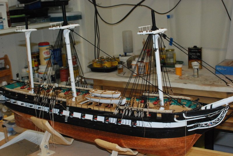
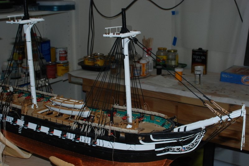
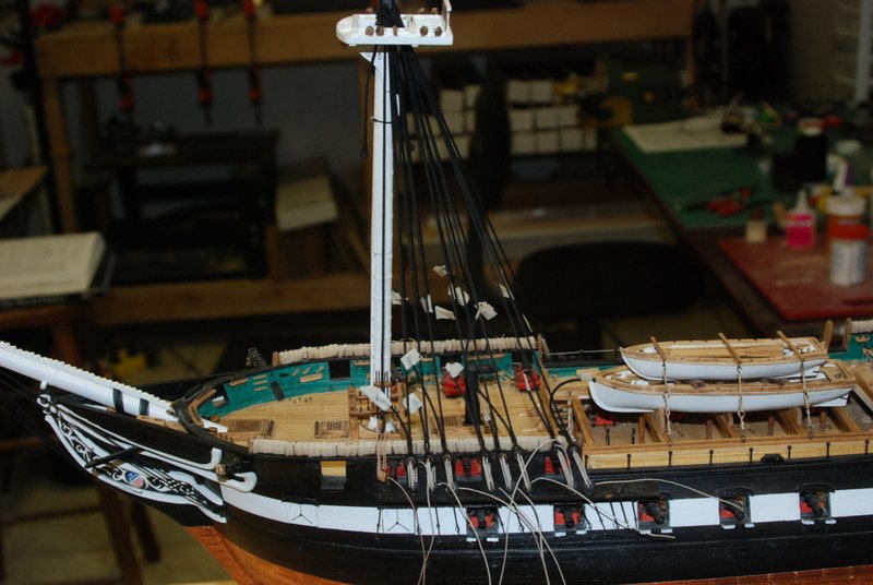
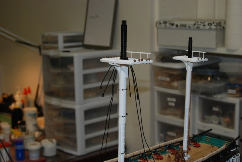
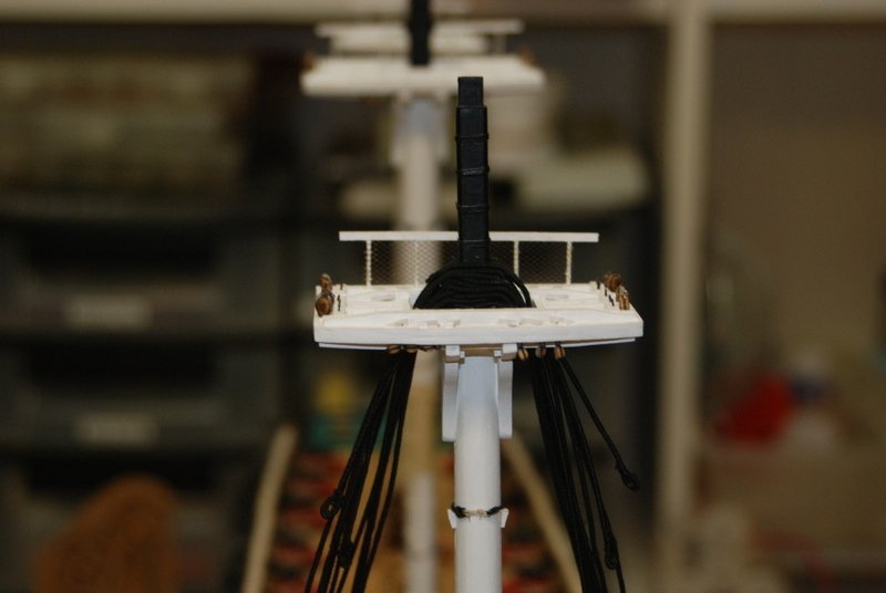
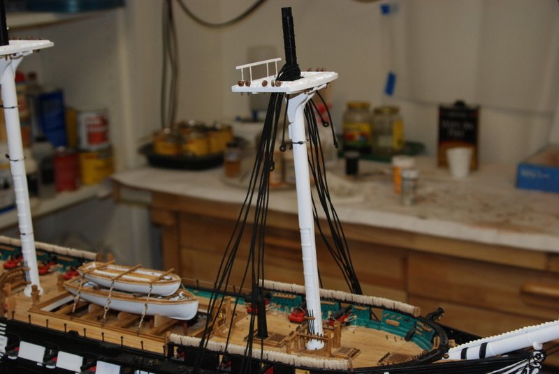
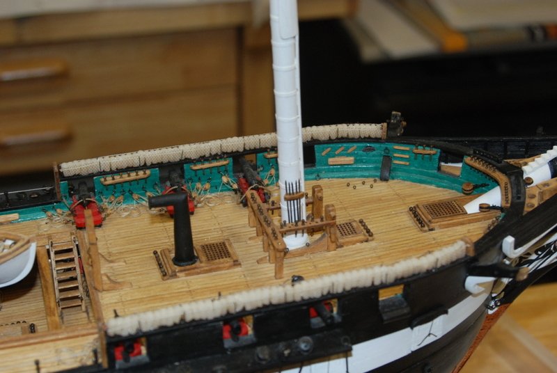
Sorry vossie, if I didn't have a whole ship load of rigging to do on my own model, I'd take you up on the offer. I do love soda and chips, though. I have a sister that lives on the other side of the Bay that I could visit too. Maybe see the birthplace of my hero, Tom Brady while in your town. Humm, then there is always a side trip to Napa. Clos Pegase and St. Clement are two of my favorites. This could be fun... California dreaming in the aftermath of a blizzard. I did have a snow day yesterday, so had some time to get the masts set. Here they are installed with the trestle trees glued on. I added the belaying pins to the mizzen pin rack, and the boarding pikes to the main and fore mast rakes. I made those from straight pins that I blackened after cutting off the heads. This morning I glued the mast tops to the trestle and crosstrees. I put the topmast and caps in place temporarily when I installed the trestle trees, so I could get the topmasts straight to the lower masts by adjusting the position of the crosstrees. Making the pendants and shrouds is next.
- 1,354 replies
-
- 10
-
-
- constitution
- model shipways
- (and 1 more)
-
I think some of this char goes all the way through! - Ha ha. I hate char. I hate the way it smells and how it makes my fingers feel after sanding it. I feel your pain, Rich!
- 1,135 replies
-
- 3
-
-
- model shipways
- syren
- (and 2 more)
-
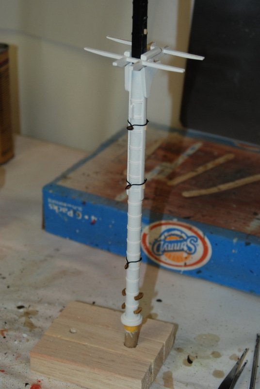
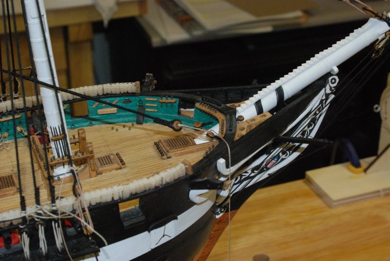
Thanks again. And once again I have changed my mind and decided NOT to add the crows feet. I am just not comfortable adding them to the Constitution, since the Hull model does not show them. I have been working on the collars for the masts and thought I'd show how I made them. I started by serving a piece of line, then seized small loops into each end, so I could make two collars at a time. I then folded the line around a bullseye and got the lengths of the legs so they had a decent gap when wrapped around the mast. I then seized a small loop into the other leg: Then I seized the bullseye into the center of the collar: After everything was trimmed, I tied a lashing line to one of the small loops and lashed the collar around the mast. I did not use a rose lashing, in case you were wondering. Here are some results: I have finished up the mast tops with all the various eyebolts and blocks, so I am finally ready to start adding the lower masts to the hull.

- 1,354 replies
-
- 9
-
-
- constitution
- model shipways
- (and 1 more)
-
Ah, I see I am not the only one with soldering issues. Good luck on your next attempt.
-
Man, you picked the wrong week to quite smoking....
- 714 replies
-
- 4
-
-
- lady nelson
- victory models
- (and 1 more)