

popeye2sea
-
Posts
1,935 -
Joined
-
Last visited
Content Type
Profiles
Forums
Gallery
Events
Everything posted by popeye2sea
-

Schooner upper yards fastening
popeye2sea replied to Michelnou's topic in Masting, rigging and sails
Very interesting rigging diagram. In my opinion most of the lines for the fore yards are mislabelled, which would lead to much confusion. Here is what I see when I look at this rigging plan. On the fore yard (the lowest yard on the fore mast) the brace has been labelled as a flag halliard. Also line number 37 appears to be the topsail sheet tackle. If you follow it up from the deck you first come to the single block for the tackle then the sheet leads up through a block hanging under the yard( next to the number 36 on the diagram) passes along underneath the yard and up through a sheave at the yard arm and then up towards the block for line number 35, which appears to be the topsail clew. This all makes sense if you are rigging as shown in the diagram with no sail set and the yard in its lowered position. However, all of the above has been labelled the fore sheet, which makes no sense at all. The fore yard has lifts that lead up to blocks just under the cap, line number 36. But there is no halyard shown for this or any of the other yards. On the topsail yard( the middle one). This is again shown in its lowered position with no sail set. The brace is labelled as the upper topsail brace. It has lifts (line 34) leading up to blocks at the collar at the top mast head. It also has no halyard shown. However, the line number 33 which is the combined topgallant sheet and clew (similar to the topsail) is missing its lower lead once it passes through the sheave at the topsail yardarm. It is mislabelled as upper topsail sheet. On the topgallant yard (the uppermost yard) , line number 31, which is the topgallant lift is labelled topgallant sheet. Once again no halyard shown for this yard With regard to the halyards, I do not know if they were led through sheaves in the mast or blocks seized to the mast but they should be placed above the point where the yard is at maximum height but below the attachment point for the corresponding lifts. Also, in my opinion, the fore topgallant backstay (number 16,17) should attach at a point closer to the topgallant stay (thats the uppermost stay). They should be working in opposition to each other. Regards, -
Schooner upper yards fastening
popeye2sea replied to Michelnou's topic in Masting, rigging and sails
The halyard and lifts perform two separate functions. One does not duplicate the other. The halyards sole purpose is to hoist the yard. The lifts control the cant of the yard. The lift also supports the ends of the yard when in the lowered position. For such light yards as could be set flying the lifts are mostly unnecessary. The yard is kept in control with the braces and through the sail via the sheets. Also unnecessary for these light sails are the reef tackles and bowlines. These eliminations considerably reduce the complexity of hoisting the sails and yards from the deck. Regards, -
Schooner upper yards fastening
popeye2sea replied to Michelnou's topic in Masting, rigging and sails
Usually a yard that is set "flying": rigged from the deck: is hoisted aloft by its halyard. The halyard would be nippered along the length of the yard so the yard went up vertically and not foul the stays on the way up. There would be no lifts or parrels used at all. The braces were either attached to the yard on deck or attached by the top men when the yard reached the level of the top where they would also cast off the nippers to allow the yard to swing horizontal again. Regards, -
Converting a Backyard Shed into a Model Workshop
popeye2sea replied to Hank's topic in Modeling tools and Workshop Equipment
In this case it probably means Significant Other. Regards -
Schooner upper yards fastening
popeye2sea replied to Michelnou's topic in Masting, rigging and sails
I meant no offense in my reply. But, what I did mean is that every square yard is hoisted by some form of halyard and every yard is controlled by braces. Unless you are talking about the very smallest of yards, like skysails, moonrakers or stunsails, they are going to have lifts and parrels also. As you move up the mast and the spars get lighter they require less power to move around, so for lower yards you may have the halyards doubled whereas they will be single for the upper yards. The parrels will get lighter as you move up the mast also, with the lower yards having perhaps three rows of trucks and the upper having two. The circumference of the line employed will reduce commensurately. If you have a particular ship in mind I could give you more specific answers. Regards, -
Schooner upper yards fastening
popeye2sea replied to Michelnou's topic in Masting, rigging and sails
Personally, I think it is a bit of a misnomer to say that the yards are fastened to the masts. They are not at all. They are hoisted by jeers/halyards: sometimes suspended by slings or lifts: and there movement is controlled by lifts and braces. The parrels hold them confined in towards the mast and allow for smoother hoisting. I think you will find that all square yards have a combination of the above in order to make them work. Regards, I suppose I should edit my response to say that in later years of steel ships some yards were indeed fastened to the mast with a fixed truss. -
Iron Band at the Heel of Masts
popeye2sea replied to Doug McKenzie's topic in Masting, rigging and sails
The term applies to both. Regards, -
Yes, but I chose that in honor of the French ship I am working on. Regards
-
Thanks for the correction. I was basing my estimate on memory. Regards,
-
I tried to do some scale work for you. Here is what I come up with. If you start with Zu Mondfeld's table for chain thickness. I took for example a 100 ton vessel requires a chain thickness of 20mm. My guesstimate is that the length of the link will be about 5 times the thickness. That gives you a length of 100mm for each link which equals 3.875 inches. You mentioned your model is 3/16 : foot or 1:64. So a scale link is 0.06 in long That works out to about 16 or 17 links per inch (LPI).. Which will be the specification you will find most chain sold by I do not know the tonnage of your vessel but I am sure you can look that up. Someone correct me if my math is wrong. Regards
-
The hanging in chains part was when they hung the bodies up in port so that other pirates could see their fate when caught. Regards,
-
Here is a copy of a page out of Seamanship in the Age of Sail by John Harland.
-
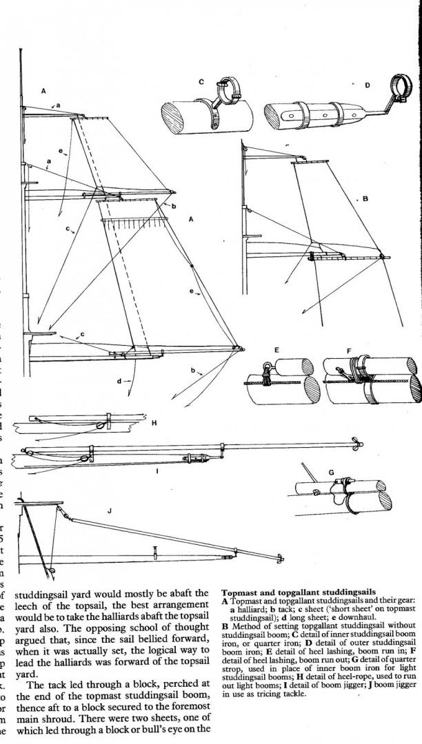
The answer is a bit complicated but I hope you get the gist. You are referring mostly to the stuns'l boom which is run out by means of a jigger tackle that is hooked on one end to the ring on the inside end of the boom and on the other end is hooked to a convenient point near the outer end of the yard arm. The same tackle can be employed to haul the boom in by hooking it to a point near the mast. Foot ropes are not needed because everything is rigged prior to running out the boom. The booms are lashed in place whether hauled in or out. At the outer end of the stuns'l boom there are seized two jewel blocks. Through the lower one of these is rove the stuns'l halyard, by which the stuns'l is hoisted up to the end of the boom. The top of the stuns'l is bent on to a short spar called the stuns'l yard. The halyard is hitched to the center of the yard. At the bottom of the stuns'l there are the inner and outer sheets attached at the clews. The outer sheet reeves through a jewel block on the lower stuns'l boom. The inner sheet is sometimes taken directly inboard. At the inside top of the stuns'l a tack line is seized and runs inboard to extend the head of the stuns'l along the yard. The stuns'ls are set flying (no lifts or braces and lightly bound to their yards to be loosed after being hoisted aloft) Regards,
-
Holes in Stem Post
popeye2sea replied to acaron41120's topic in Building, Framing, Planking and plating a ships hull and deck
Unless I am mistaken, Mayflower was built in a period prior to the use of bobstays for the bowsprit so those holes could be for the fore sail tacks which were often taken through holes in the stem before leading aboard on the opposite side. Regards, -
I see an interesting phrase that I do not know the meaning of. Can anyone shed some light on "half-seas over"? Perhaps it means mostly drunk?
-
In the first picture the lead for the spritsail yard brace seems at least probable. However in the second photo the lines leading from the spritsail yardarms to the fore and fore topmast yard arms do not make any sense. The same can be said for the lines from the main topsail yard to the fore yard and the main royal yard to the fore topsail yard. In fact I see many questionable leads throughout the whole rig. It looks like whomever rigged this model took the approach of lets throw as many lines on this as possible regardless of function. Regards,
-
The only reference I found in Falconers Marine Dictionary referred to sharp as in sharp bottomed as opposed to flat or full bottomed. Regards,
-
Yes
-
At 1:250 scale a 2mm block works out to be about 20 inches which is a pretty big block. It would be used for a line of about 2 inch diameter. That being said, I think the 2mm blocks would probably look good. I don't think you are going to find any smaller unless you want to substitute tiny beads. Regards,
-
Normally, the blocks on a yard are positioned relative to the center of that particular yard. For example: quarter blocks to be placed just outside the yard cleat. Clew line blocks to be placed one third the distance out from the center. Brace blocks placed just outside the yard arm cleat. etc. Regards,
-
Deadeyes and ratlines and shrouds, oh my!
popeye2sea replied to Brewerpaul's topic in Masting, rigging and sails
Sorry, I'm around early 19th century ships and history so much that the the language almost comes naturally to me. Ask away. I'm here to help. Regards, -
Deadeyes and ratlines and shrouds, oh my!
popeye2sea replied to Brewerpaul's topic in Masting, rigging and sails
My two cents worth: Mount the lower deadeyes to the channels with the metal strops and chains. Constructing the shroud pairs: Measure the length from the mast head to the deadeyes and then double it. Use this length to make each shroud pair, then add some extra for turning in the upper deadeyes. Middle the shroud and mark the center point. If you wish to add worming, parcelling and serving do so now by servicing the middle third of each shroud pair. The forward most shroud is serviced its entire length. Form a bend in the center of the shroud pair of a size that will fit over the mast head and mark the point where the shroud pair passes over the trestle trees below the bolster. Clap on a round seizing just below this point. It is easier if you do all the above prep work off the ship. Complete all of your shroud pairs. If you have an odd number of shrouds one one each side will be mounted singly with its own eye or the port and starboard single shrouds will be joined by means of a cont splice Hoisting aboard the shrouds: If you are mounting mast tackle pendants they go over the mast head first. Use the jig that Mark mentioned above to set the position of the upper deadeyes for the first shroud pair. Put the eye of the first starboard shroud pair over the mast head. Lead the shrouds down and turn in the upper deadeye. Where the end crosses behind the standing part (looking from the outside of the ship) clap on a throat seizing. The seizing will look like it is laying on top of the deadeye with the end of the shroud parallel to the standing part. Bring the end of the shroud up alongside the standing part and clap on a round seizing a short distance above the throat seizing and then another round seizing the same distance again above that. Don't trim the end of the shroud above the seizings until you have set up all of the shroud pairs for their full due with the laniards. You can do all of this work off the ship too if you mark where the shroud end crosses at the top point of the upper deadeye Next put the first port shroud pair over the mast head. Repeat alternating starboard and port pairs until all the shrouds are over the mast head Reeve the laniards through the upper and lower deadeyes, but do not haul taut yet. Next over the mast head are the stays. Setting up the shrouds: Once the stays are hauled forward and set up taut you can then set up the shrouds. Haul taut the laniards in pairs alternating port and starboard so that you maintain equal tension on all shrouds. I have heard it said that it is easier to maintain a balanced tension if you start with the aft-most pair first (personally untried). Once the shroud is set up the laniard end is passed between the throat seizing and the upper deadeye with a hitch and the end is stopped to is own part. Well maybe that was five or six cents worth. Regards, -
Rigging Instructions 1/96 Revell Constitution
popeye2sea replied to kruginmi's topic in Masting, rigging and sails
Running rigging can be roughly broken down into two parts: that which controls the movement and support of the yards and that which controls the sails. The rigging instruction sections will be nearly identical with respect to the lines which control the yards. Every yard will have halyards, lifts, braces. The differences will become apparent when you consider the sails. Sails are controlled by sheets, tacks, clews, bunt lines and leech lines. Fore and aft sails have uphauls and downhauls. Depending on which sails you choose to model will determine which lines you can exclude from your plan. I hope that makes things a bit clearer. Regards, -
The spanker and the driver were originally different sails. The spanker sets from a gaff on the mizzen mast. It started out as the loose footed mizzen sail which was itself a modification of the lateen mizzen of the 17th century. At this point it is still referred to as the mizzen sail. By the late 18th century the foot was extended by a boom. The driver was a sort of studdingsail that was set in addition to the mizzen. The head of this sail was extended by a small yard that was hoisted by a halyard in the center to the peak of the gaff. When set square the foot was sheeted out to a boom lashed athwartships to the taffrail and extending out from the sides of the ship. The driver could also be set more fore and aft as sort of an extension or enlargement of the mizzen in which case its boom was lashed to extend the boom of the mizzen. (BTW, I think it is at this point that you start to have problems with interference with the ensign flag staff) Eventually, this enlarged and extended fore and aft mizzen/driver combination becomes standard and is called the spanker sail. Regards,

