DONATION DRIVE - SUPPORT MSW - DO YOUR PART TO KEEP THIS GREAT FORUM GOING!
×

popeye2sea
-
Posts
1,935 -
Joined
-
Last visited
Content Type
Profiles
Forums
Gallery
Events
Everything posted by popeye2sea
-

makeing sense of rigging plan abbreviations ?
popeye2sea replied to spongbob's topic in Masting, rigging and sails
Spongbob wrote: the TR designated mast and yards i take it now after looking again must certainly be the back mitzen for certain Spongbob, The TR is a poorly printed PR and it stands for the foremast. This is confirmed by the diagram in the lower left corner of your plans. The ME labeled spars are for the mizzen. That's the one that has a gaff and a boom. Look at that diagram in the lower left. Picture it as a complete ship viewed from the port side. Starting on the left, the spar that points at an angle to the left is the bowsprit. Next to it on the right is the fore mast, followed by the main and then the mizzen with its gaff and boom on the far right. Spongbob wrote: im thinking the 80 1 80 2 80 3 80 4 are the jibb spare The ones you are calling 80-1, 80-2, etc. are actually labelled BO and that is definitely the bowsprit and jib Regards, -
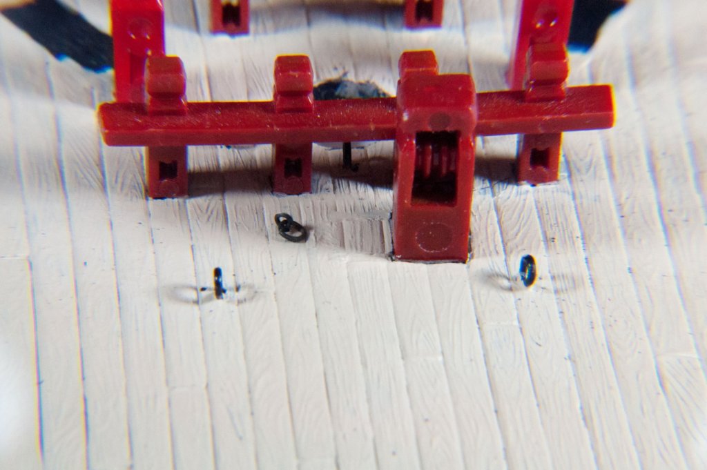
That is outstanding work!! You even have thump mats around the eyebolts in the deck!
- 742 replies
-
- 5
-

-
- constitution
- frigate
- (and 1 more)
-
makeing sense of rigging plan abbreviations ?
popeye2sea replied to spongbob's topic in Masting, rigging and sails
The designations are from the Italian words : Main mast - Albero Maestro Fore mast - Albero Prodiero Mizzen mast - Albero Mezzana Bowsprit - Bompresso The underlined first two letters are the designation (albero translates to mast) Regards, -
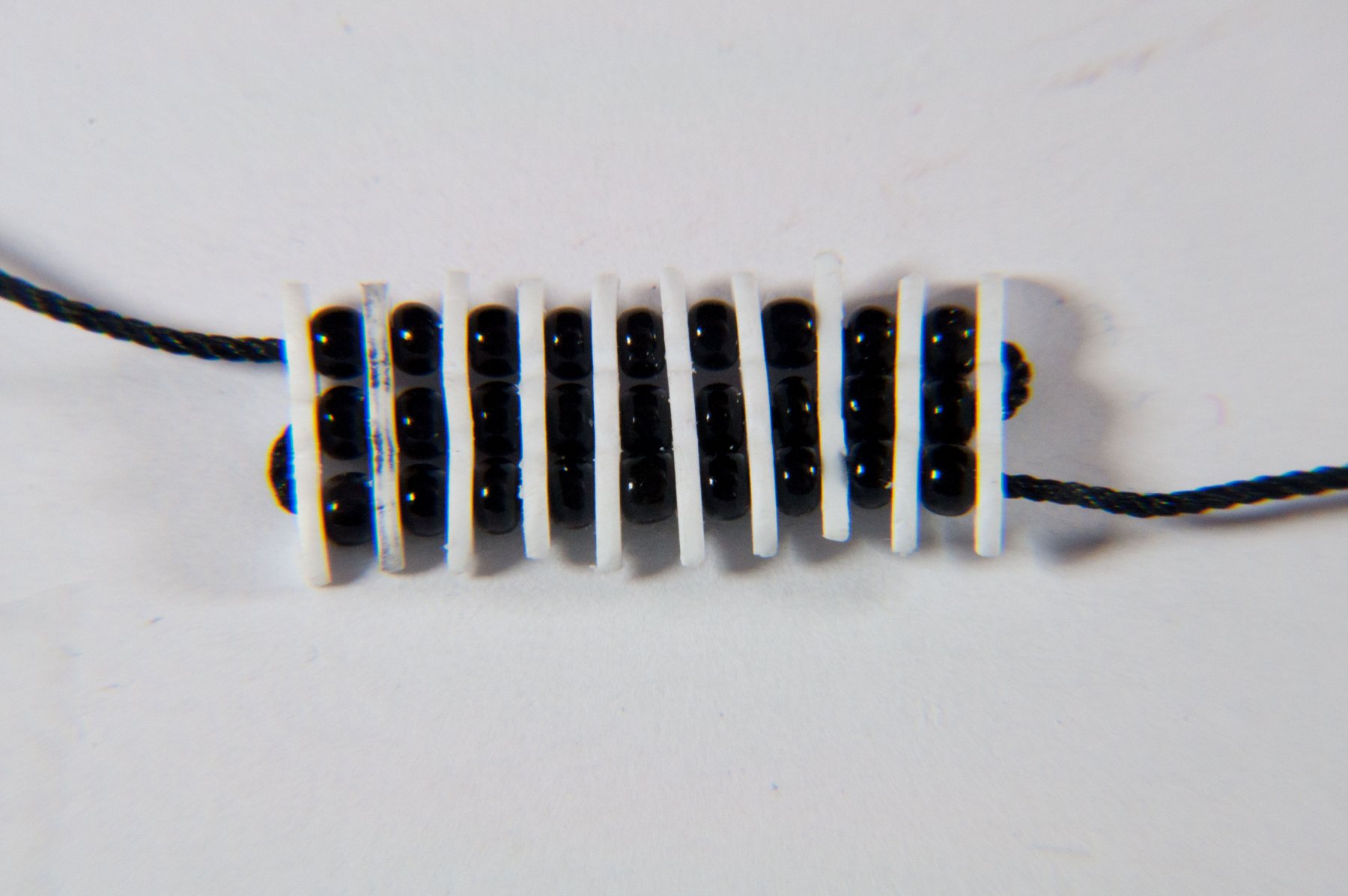
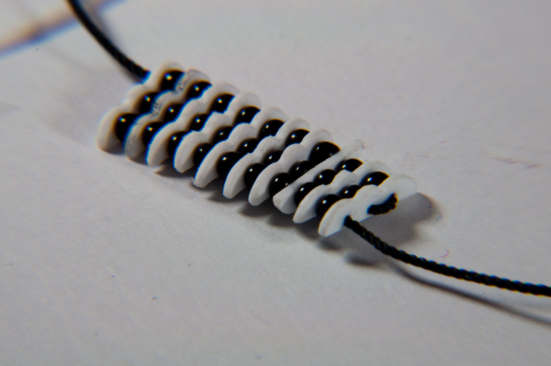
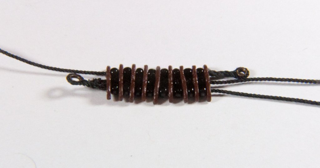
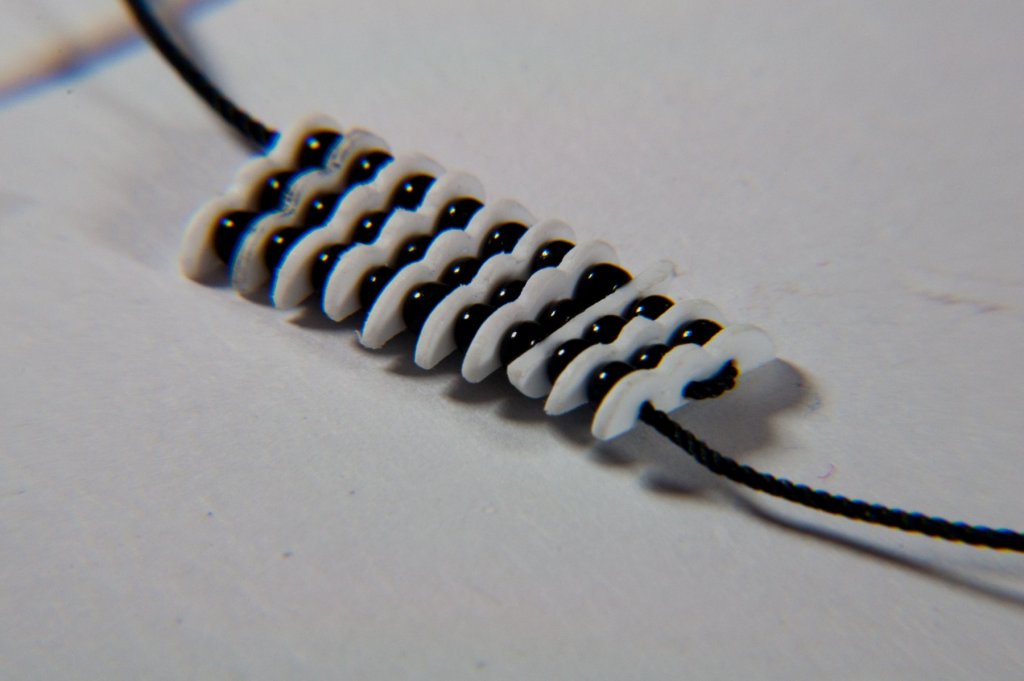
Here is the put together yard parrel. It works, sort of. It needs to be reduced by 1 or 2 segments. And I probably need to lash together the eye and the hauling part so that it ends up middled at the end of the parrel . The pull will be more even. The center parrel rope will be finished off with a stopper knot. The center truck is a slightly different shape in order to accomodate additional holes for the nave line
- 196 replies
-
- 8
-
-
- plastic
- soleil royal
- (and 2 more)
-
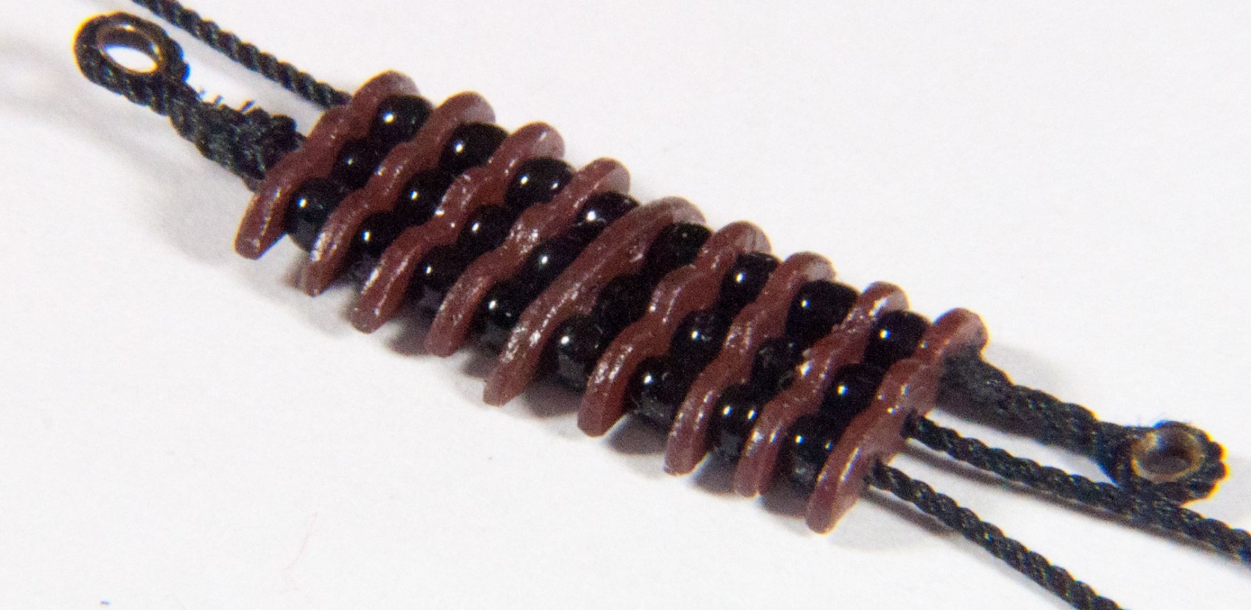
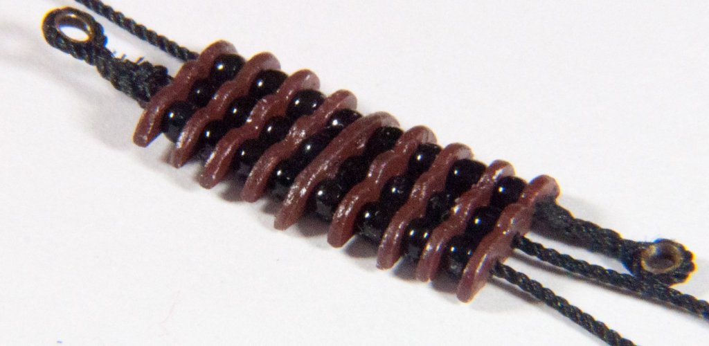
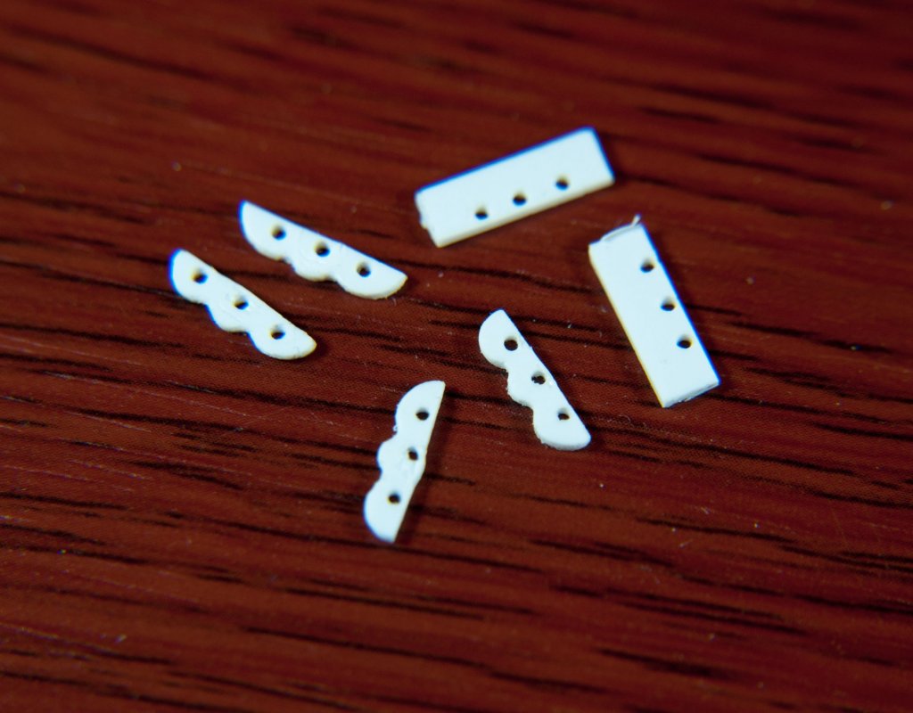
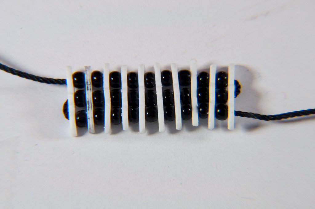
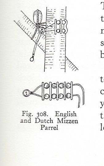
I started work on the main yard parrel. Still trying to determine how these were rigged. The sources I have are all confused on the issue. There are lots of guesses but nothing definitive. And the diagrams I have seen do not look like they would actually work. Anyway, here is what I have so far. The parrel trucks are cut from .03 x .125 styrene strip. Holes are drilled for the parrel ropes and then the trucks are given their final shape. The parrels themselves are 10/0 glass beads I purchased from a craft store. This is not the final configuration. My initial thought is to reeve the parrel ropes such that there will end up being a thimbled eye splice at the top left and bottom right corners. The other end of the ropes will emerge from the opposite corners and be left long enough to pass around the yard, through the eye, and then to a tackle at the deck. The trucks will be painted. Anyone have thoughts on the proper way to rig a yard parrel? I'm eager to hear what others have done.
- 196 replies
-
- 5
-
-
- plastic
- soleil royal
- (and 2 more)
-
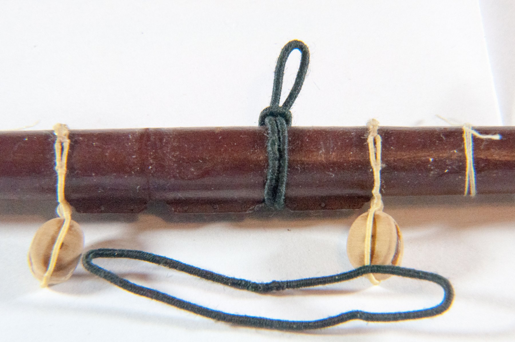
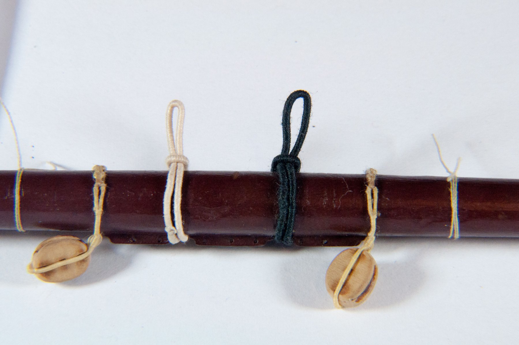
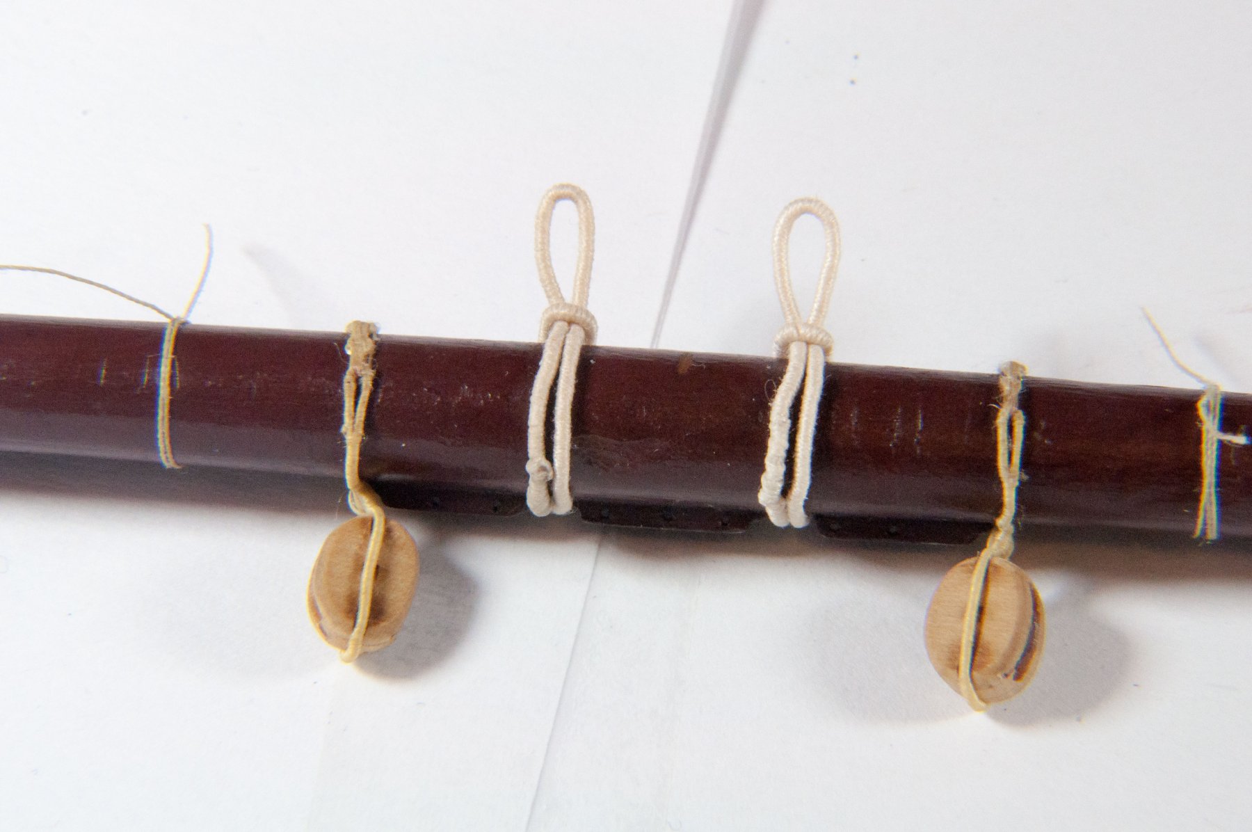
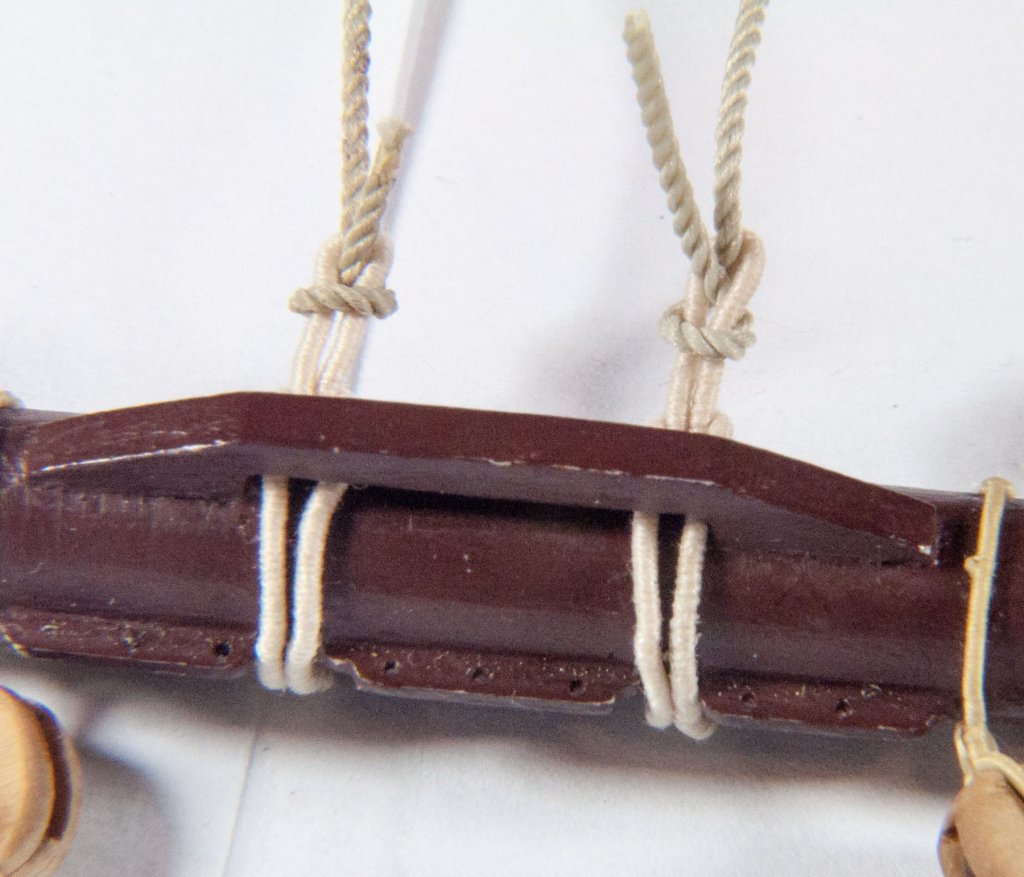
Another small update. I decided that the straps for the main yard tyes were too long. Plus I did not like the contrast of the tarred strap with the natural tye. So here is the quick correction. First photo is the old strap. These straps are made on a serving machine by taking 12 or so turns between the prongs then serving over, leaving an eye at both ends. The eyes are then lashed together end to end to make a continuous loop. This results in an unserved gap over the eyes that is then served manually (not using the machine). The result is called a selvagee. I also use this method, or variations of it, to make the strops of blocks. The second photo is a comparison of the new and old straps. The blocks on either side are the main sheet blocks rose lashed in place. The other unfinished loops are place holders for blocks that still need to be installed. Here are both of the new straps installed. This last photo will give you some idea of how the tye attaches to the strap. When installed on the ship a seizing will be clapped on above the hitch to secure it.


- 196 replies
-
- 10
-
-
- plastic
- soleil royal
- (and 2 more)
-
Slightly on a side topic. A square rigger can not sail closer than about 6 points to the wind. For example, with the wind from the North the ship could sail no closer than ENE or WNW. Regards,
-
It is my opinion that the flag halyard should be your thinnest possible rope and come down all the way to the deck. Regards,
-
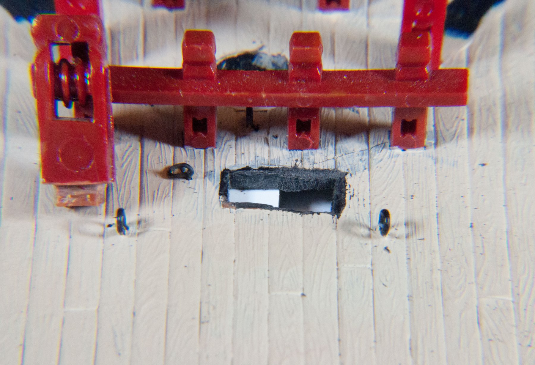
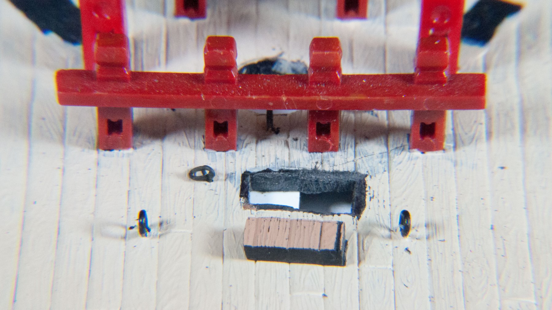
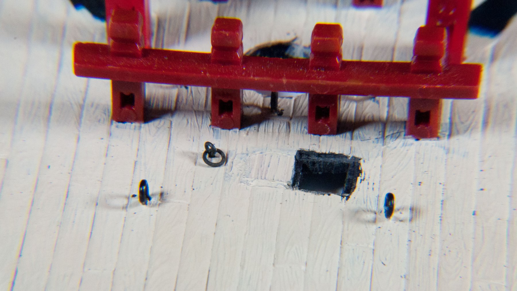
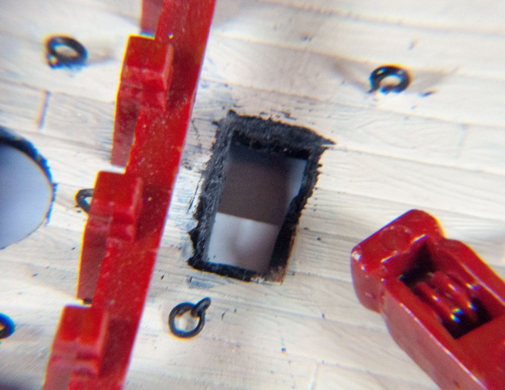
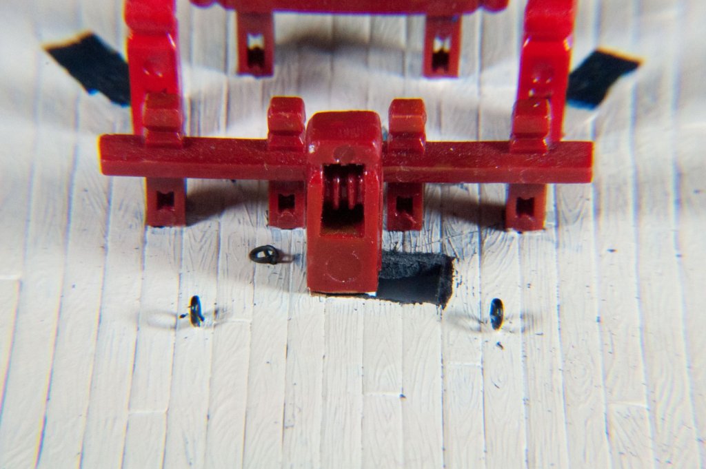
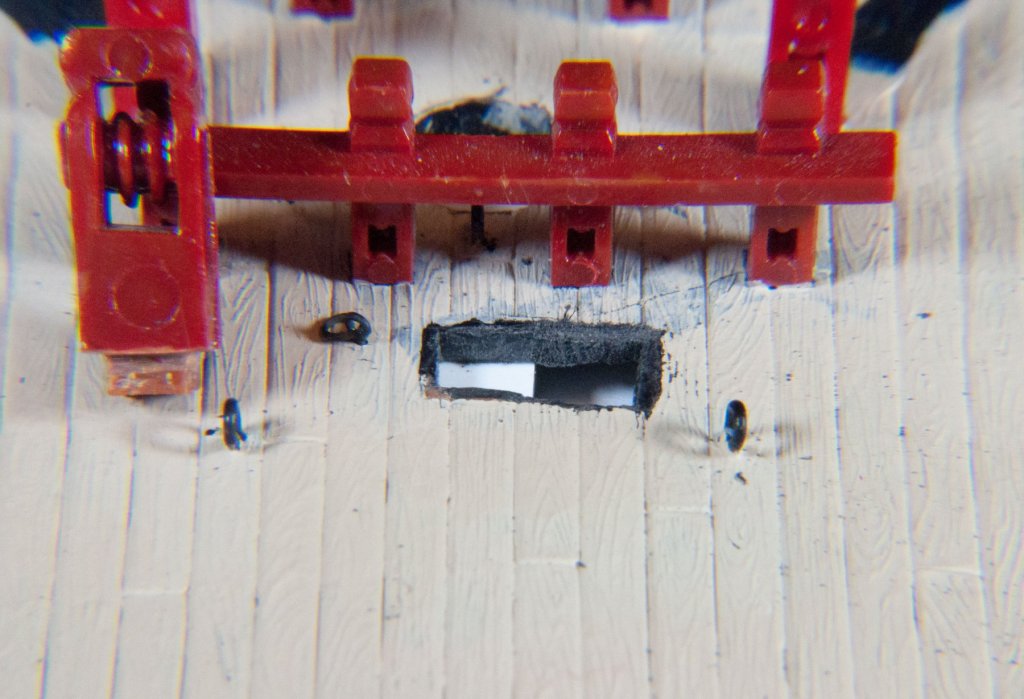
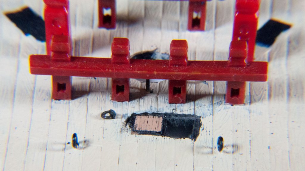
In a previous post I spoke about shifting the fore halyard knight off centerline. Here are the promised photos. The knight is removed and the hole is lengthened to starboard approximately it's own width. A strip of styrene is glued beneath to hold up the new deck. This photo shows the old centered location of the knight. A small section of matching deck was cut from a spare forecastle deck (old kit). The section is trimmed and fitted. Gaps filled and deck painted. Knight remounted in new location and paint touched up. Regards, P.S. I really like the new set up I am using for photography. I am using a macro lens filter attachment and photo flood lamps. Post processing using Adobe photoshop. Still think there is room for improvement with the lighting and shadows.


- 196 replies
-
- 7
-
-
- plastic
- soleil royal
- (and 2 more)
-
The halliard forms a continuous loop. The flag has a type of bolt rope running through the hoist side with an eye at the top to take the toggle on the halliard. The bottom of the bolt rope is left as a long tail on the flag terminating in a toggle that engages an eye on the other end of the halliard. The halliard passes through a block at the peak of the gaff. When the flag is run up the two parts of the halliard are taken together around one cleat. Hope that is understandable. I don't have a picture. Regards,
-
I think going with the full beard is the better option. I would put the hole right through the mouth. In my opinion, there would be another smaller hole further down to take the spritsail sheet. This could pass through the beard. Regards, Henry
- 2,699 replies
-
- 4
-
-
- heller
- soleil royal
- (and 9 more)
-
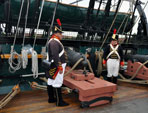
Here are a couple of pictures that might help. Regards,
-
Excellent point, Bluenose, and something that did occur with some frequency. Captains would often modify the rig to improve the ships sea keeping ability. One of the reasons for the disappearance of the spritsail topmast in the late 17th and early 18th centuries was the fact that it had a depressive effect on the bow of a ship. Regards,
-
Of course, even though there may be evidence presented within the paintings, the rig of any ship was never static. It could and often did change based upon the desires of the Captain/Sailing Master/Admiralty, etc. You might at some point just have to go with your gut. Regards,
- 2,699 replies
-
- 3
-
-
- heller
- soleil royal
- (and 9 more)
-
Nice job!!
-
I almost don't know how to answer this because I hesitate to suggest a path that you may find tedious or frustrating, but to my mind nothing looks better than the real thing. Knots were never used to fasten anything on a ship. There were bends, hitches, splices, seizings, lashings, etc. You may want to reference a copy of something like The Art of Rigging by Steel to get an idea of what was used where. For instance, deadeyes are turned in on the end of shrouds using a throat seizing and two round seizings. Blocks were lashed to other lines through the eye of their strop or attached to a spar by a rose lashing. Depending on the scale of your model these can be replicated, but to do so adds a bunch more work and time. You may find that this is too much effort, but the results can add an amazing look of authenticity to your rigging. As far as whipping goes, I would only do it on the larger lines like shrouds or stays. It really wouldn't be very visible on smaller stuff. I would combine the whipping with the end seizing by simply continuing to take 4 or 5 turns around the bitter end of the shroud finishing the whipping by passing the end under the last two turns or make a clove hitch. A drop of white glue will secure the hitch and then trim the shroud above the whipping. All that being said about no knots. One of my best friends is the constrictor knot. It is basically a clove hitch with an extra tuck under one of the turns. When you pull it tight it will not loosen. I have used it to start seizings, lashings, and servings. The neat thing about it is you do not end up with a big unsightly knob of a knot. (Try using the constrictor for the last two turns of the whipping. You might not even need any glue to secure it after that!). Like I mentioned, all that is a lot of extra effort. There are a lot, lot, lot of modelers that will give you simple, easy, effective methods of fastening, but me being something of a rigging nerd, I thought I would put my two cents in. Regards,
-
The purpose of the lanyards was to be able to adjust the shrouds as needed. There are occasions were additional tension was applied to counteract forces on the mast. The foremost shroud was occasionally slacked off to allow for bracing the yard up more sharply. Also, no matter how well set up the mast would 'work' or move to some extent. There would always be some adjustment of the shrouds necessary at some point. Conversely, shrouds set up too tightly might cause a mast to be sprung because it was too stiff and could not work. Lanyards (with deadeyes or hearts) are employed because in a block and tackle the enormous forces involved would be concentrated on two points; the pins of the sheaves of the blocks. Lanyards and deadeyes allow you to spread that load over six solid points not susceptible to breakage like a sheave pin. Regards,
- 54 replies
-
- 11
-
-
Fore and aft rigging questions
popeye2sea replied to SardonicMeow's topic in Masting, rigging and sails
Here is the info that I have. It may be that it varied somewhat for different rigs. 1. the jib downhaul would be led through a few hanks to keep it from hanging loose. 2. The tack runs to an eyebolt at the deck near the mast. Sometimes with a tackle. 3. The boom topping lift is double. 4. Brails are paired and bend seperately to the sail on either side of the same cringle. Regards, -
Another take this for what it's worth item: All rope was tarred during the laying up process of making it. It is just a matter of how much tar was then added to prevent the wet from getting into the fibers that determined how dark the line got. Bottom line. You really can't go wrong with whatever color you choose. Just don't choose white. Regards,
-
I know it is common for the main and fore knights and even other knights located about the deck. For those it is absolutely necessary to have the line pass through a sheave at the bottom. You would have massive problems if you tried to belay directly to the head of the knight. But I have not seen it before at the beakhead bulkhead. The line there can be redirected using the rail itself. Regards,
- 196 replies
-
- 3
-
-
- plastic
- soleil royal
- (and 2 more)
-
As far as I can tell during this period the tacks and sheets did not come inboard through sheaved holes. Sometimes they used decorated holes (lion heads and such) and other times they used chesstrees as fairleads. I am not sure what would be proper about belaying pins. My reading is that they were not much used in this period, however I have been leaning towards using the pin locations on the side bulwarks but replacing the plastic ones with brass. I know that they would have been wood but I like the contrast with the royal blue bulwarks. The lines to the beakhead bulkhead will remain tied off to the rail stanchions. Speaking of the beakhead bulkhead, I have seen a model of the SR (I believe it is M. Saunier's) with sheaves let into the base of the rail stanchions to redirect the lines up to the stanchion head. Do you know if this was actually done? I am thinking of adding them into mine. The list of upgrades keeps getting longer I wish I had more time to get back into the model. It is sitting here by my desk calling to me. I am getting some outstanding projects finished that should free up a bit of time. Regards,
- 196 replies
-
- 4
-
-
- plastic
- soleil royal
- (and 2 more)
-
It's really very simple. Everything in the rigging needs to get to or be fixed in to position in three dimensions: up/down, right/left, and forward/back. Now put a rope on everything such that it pulls in those directions (down is mostly taken care of by gravity). If the object is heavy add a way to multiply the force (block and tackle). Try not to foul or tangle the lines. There, I just described 99% of the rigging for all ships! Sounds silly but it's true. Regards,
-
Model Shipway Ratline tool
popeye2sea replied to fnkershner's topic in Modeling tools and Workshop Equipment
I wonder what would happen if you were even just a little off in alignment of the mast or deadeyes. Even a minor adjustment looks like it would pull the whole array out of wack. Regards, -
To be honest, it seems rather strange to me to have a gaff rigged sail here in the first place. A better option, especially with a square fore sail set, would be a stay sail. Regards,